XTreme EFIS - STRATOMASTER Instrumentation MGL Avionics
XTreme EFIS - STRATOMASTER Instrumentation MGL Avionics
XTreme EFIS - STRATOMASTER Instrumentation MGL Avionics
- No tags were found...

You also want an ePaper? Increase the reach of your titles
YUMPU automatically turns print PDFs into web optimized ePapers that Google loves.
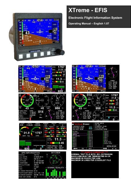
<strong>XTreme</strong> - <strong>EFIS</strong>Electronic Flight Information SystemOperating Manual – English 1.07
<strong>XTreme</strong>-<strong>EFIS</strong> Operating Manual Page 2IntroductionThe <strong>XTreme</strong> is a compact, multifunction electronic flight information system intended as a main flight instrument in smalleraircraft or as a backup/secondary flight instrument in larger aircraft. The <strong>XTreme</strong>, which fits a standard 3 1/8” instrumentpanel hole, contains all the necessary functionality to replace several flight and engine monitoring instruments.All information is displayed in an easy to read format on a high resolution wide viewing angle 4.3” sunlight readable colordisplay.The <strong>XTreme</strong>'s light weight, small size and high level of functionality makes it an excellent choice for all types of noncertifiedaircraft.1 FeaturesHardware:• Powerful 32 bit ARM processor• 4.3” high resolution 480x272, sunlight readable, wide viewing angle, 600 nits TFT LCD display• LED backlight (brightness can be adjusted for low light flying conditions)• Fits standard 3 1/8” aircraft instrument panel hole• SD Card interface for data recording, user splash screens, checklists, graphic information pages, firmwareupgrades, navigation and route files etc• 1/8” NPT female fittings for Altitude and Airspeed pitot tube connections• 1x RS232 communication port (Altitude encoder/VP-X/CO Monitor)• 1x <strong>MGL</strong> <strong>Avionics</strong> Airtalk communication port• 1x <strong>MGL</strong> <strong>Avionics</strong> RDAC communications port• 1x CAN communication port• Rotary control plus 5 independent buttons for easy menu navigation and user input• External alarm switch output for an external indicator lamp etc• Built in 50 Channel GPS receiver with over 1 million effective correlators with high immunity to jamming• GPS Time To First Fix (TTFF) of less than 1 second• External active GPS antenna connection• Support for an internal or an external GPS receiver• Built in RTC (Real Time Clock)• Wide input supply voltage range of 8 to 30V DC• Built in voltage reversal and over voltage protection for harsh electrical environments• Light weight design<strong>EFIS</strong>:• Attitude display. Note (1)• Magnetic heading indication. Note (2)• Heading bug• Precision altimeter from –1000ft up to a maximum of 30 000ft (-304m to 9144m). Altitude can be displayedin feet or meters.• Altitude bug• Airspeed indicator (16mph to 250mph), 1mph resolution. Airspeed can be displayed in mph, km/h or kts• Digital and analog VSI indicator . Scale of 1000ft/min, 2000ft/min and 4000ft/min / 5m/s, 10m/s, and 20m/s.Resolution of 1ft/min, 1m/s• Serial Altitude encoder output via the RS232 port• Density altimeter• OAT (Outside Air Temperature) display using an external OAT probe• Supply Voltage display• Stopwatch timer• Automatic/Manual flight timer• RTC (Real Time Clock)• Glide and climb ratio indicator
<strong>XTreme</strong>-<strong>EFIS</strong> Operating Manual Page 3• Barometer (actual local pressure)• TAS (true airspeed) display• G-Force indication. Note (1)• Wind speed and wind direction indication. Note (2)• Turn Indicator. Note (1)• Slip/Skid indicator. Note (1)• CDI indicator• Waypoint and Route navigation• GPS Flight Path (calculated artificial horizon based on GPS information)• CO Monitor. Note (5)Engine Monitor: Note (3)• 1x Engine RPM• 1x Rotor RPM• 1x Manifold pressure• 1x Oil pressure input• 1x Oil temperature input• 2x Auxiliary analog channels (Pressure/Temperature/Current)• 12 Channel EGT/CHT display• 2x Fuel Flow• 2x Fuel Level• Special Rotax 912/914 engine monitor mode utilizing the standard built in Rotax NTC CHT probes• Programmable maintenance timer for scheduled routine engine maintenance• Engine display screens are automatically configured to optimize screen space depending on whatparameters are been displayed• User settable Hobbs meter (password protected)• Fuel range / endurance based on TAS or GPS ground speed• Supply Voltage display• Current monitor to measure charge/discharge currents. Note (4)• Engine leaning feature• Vertical Power VP-X display. Note (6)General:• Alarms on most displays• Programmable maintenance timer for scheduled routine engine maintenance• Programmable airframe timer for scheduled airframe maintenance.• Records maximum and minimum values of most displayed values• Built in black box recorder – records all flight data, engine, attitude and GPS data to SD card. Data can beexported to Google Earth, Microsoft Excel, etc.• Includes a 1000 entry automatic flight log (Records start date&time, flight time, pilot number, Hobbs time,maintenance time, max altitude, airspeed and VSI reached during the flight)• User configurable start up (Splash) screen• Unlimited configurable checklists• Unlimited configurable graphic information displays• Automatic or manual local magnetic variation• Dual menu system for quick item selection and user setups• Sunrise/Sunset calculator• Firmware upgrades via SD Card• 1 year limited warranty(1) Requires optional <strong>MGL</strong> <strong>Avionics</strong> AHRS sensor unit (SP4/SP5/SP7)(2) Requires optional <strong>MGL</strong> <strong>Avionics</strong> compass sensor unit (SP2/SP6)(3) Requires optional <strong>MGL</strong> <strong>Avionics</strong> RDAC (Engine monitor) unit(4) Requires optional <strong>MGL</strong> <strong>Avionics</strong> current monitor sensor(5) Requires optional CO Guardian CO detector(6) Requires optional Vertical Power VP-X unit.
<strong>XTreme</strong>-<strong>EFIS</strong> Operating Manual Page 42 <strong>XTreme</strong> Layout2.1 Front layout4.3” high resolution (480x272),sunlight readable, wide viewingangle, 600 nits LCD displaySD card slotRotary control. Pressto access the quickselect menusPress for previousdisplay screenSoft keysPress to advance to thenext display screen2.2 Rear layoutFits into a standard3 1/8” instrumentPanel holeM4 Mounting BoltsGPS AntennaconnectionD15 Input connector(Power,Communications,OAT probe and alarm output )1/8” NPT Pressure port(Pitot tube)1/8” NPT Static Port
<strong>XTreme</strong>-<strong>EFIS</strong> Operating Manual Page 53 Display ScreensPress the left or right most soft keys to cycle through the display screens. The display screens can be enabled/disabled inthe “DISPLAY SETUP” menu option.<strong>EFIS</strong> DISPLAY <strong>EFIS</strong>/EMS DISPLAY <strong>EFIS</strong>/HSI DISPLAYVFR DISPLAY VFR/EMS DISPLAY EMS DISPLAYELECTRICAL SYSTEM DISPLAY GPS DISPLAY CHECKLIST/INFO DISPLAY
<strong>XTreme</strong>-<strong>EFIS</strong> Operating Manual Page 63.1 <strong>EFIS</strong> displayThe <strong>EFIS</strong> information is displayed in a full screen format.3.1.1 Heading tapeThe heading tape is located at the top of the <strong>EFIS</strong> screen. The heading bug will be displayed in yellow if it is in the viewarea else it will turn cyan. The heading bug will always point to the shortest direction to achieve the correct heading. Theheading bug can be changed in the quick select menu. The heading is corrected for attitude while pitching and rolling(<strong>MGL</strong> <strong>Avionics</strong> AHRS unit required (SP4/SP5/SP7)).The Compass parameters can be configured in the “COMPASSSETUP” menu. The small magenta triangle indicates coarse over ground from the GPS receiver. The coarse over groundindicator will only be displayed when a valid 2D or 3D GPS fix has been achieved. The heading tape source of informationcan be from a magnetic sensor (<strong>MGL</strong> <strong>Avionics</strong> SP2/6) or from the coarse over ground value from the GPS receiver. Whenthe heading source of information is from the GPS receiver then the heading will be displayed in magenta.3.1.2 Ground SpeedThis is located in the top left corner of the <strong>EFIS</strong> display. The ground speed value will only be displayed when a valid 2Dor 3D GPS fix has been achieved.3.1.3 Local Pressure Settings (QNH)This is located in the top right corner of the <strong>EFIS</strong> display. Turn the rotary control to change the local pressure setting. Thelocal pressure can be displayed in mB or in “HG.3.1.4 True Airspeed (TAS)This is located in the bottom left corner of the <strong>EFIS</strong> display.What is TAS and how is it calculated ?TAS is indicated airspeed (ASI) compensated for altitude and temperature. Often pilots ignore the effect of temperatureand only take altitude into account when converting ASI to TAS. For practical purposes this is quite accurate and gives agood reflection on your true airspeed. Keeping in mind that ASI measurement is subject to errors caused by airflowaround your aircraft, there seems little point in taking this calculation to absolute resolution.Again, we have decided to use a formula often used by pilots. This way the instrument reading will agree with what pilotsare used to.Add 1.75% of IAS per 1000 ft (304.9 m) increase in altitude above sea level.We assume here that IAS = RAS (rectified air speed).
<strong>XTreme</strong>-<strong>EFIS</strong> Operating Manual Page 73.1.5 Airspeed TapeThis is located to the left of the <strong>EFIS</strong> display. The Vso (Min safe speed, landing), Vs1 (Min safespeed, normal), Vfe (Max flap speed), Vno(Max maneuvering speed) and Vne (Max exceedspeed) can be configured in the “AIRSPEED SETUP” menu.Vne (Max exceed speed)Vno (Max maneuvering speed)Vfe (Max flap speed)Vs1 (Min safe speed, normal)Vso (min safe speed, landing)3.1.6 Information display area 1The 1 st line is the GPS fix status. AQ=Acquiring (Red text color), 2D=2D fix, 3D=3D fix.The 2 nd line is the OAT value. Outside air temperature can be measured using the external temperature probe. The OATparameters can be configured in the “OAT SETUP” menu.The 3 rd line is the supply voltage value. The <strong>XTreme</strong> can measure the supply voltage up to 30Vdc. The supply voltageparameters can be configured in the “VOLTS SETUP” menu.The 4 th line is the short name of the currently selected active waypoint.3.1.7 Altitude TapeThis is located to the right of the <strong>EFIS</strong> display. The altitude bug will be displayed in yellow if it is in theview area else it will turn cyan in color . The altitude bug can be changed in the quick select menu. Thealtitude parameters can be configured in the “ALTITUDE SETUP” menu.3.1.8 VSI displaysThe <strong>XTreme</strong> provides an analog VSI as well as a digital readout. The VSI scale can be set for a scale of1000ft/min, 2000ft/min or 4000ft/min / 5m/s, 10m/s, or 20m/s. The VSI parameters can be configured in the “VSISETUP” menu.
<strong>XTreme</strong>-<strong>EFIS</strong> Operating Manual Page 83.1.9 Information display area 2The 1 st line is the carbon monoxide PPM value from the CO Guardian Detector (CO Guardian detector required).The 2 nd line is the density altitude value. Density altitude is a perceived altitude that pertains to your current altitude andtemperature (and to a lessor extent on your current moisture content of the air). Density altitude is relevant forperformance calculations of your aircraft. Density altitude affects the performance of your engine, propeller and airfoils.The most noticeable affects of density altitude are length of take-off and landing runs and the ability of your aircraft tocarry weight. There are several methods to calculate density altitude, all result in readings that are very close to eachother. We decided to implement a popular formula that is often used by pilots to calculate density altitude at their location.T=Ambient temperature in degrees CTs=15-.0019812*Pressure Altitude(ft)Density Altitude=Pressure Altitude(ft)+118.6*(T-Ts)The 3 rd line is the current G-Force value. (<strong>MGL</strong> <strong>Avionics</strong> AHRS unit required (SP4/SP5/SP7)).3.1.10 Timer areaThe 1 st line is the timer. The Timer can be configured in the quick select menus.The 2 nd line is the flight timer. The flight time is automatically reset to zero when a new flight isstarted (manual or automatic flight detection). The flight timer can be started in the quick selectmenu (Manual selection).The 3 rd line is the local time. Local time normally includes a offset from Zulu time. The time offsetcan be setup in the “TIMERS SETUP” menu.3.1.11 Slip/Skid indicatorThis is located at the bottom of the display. The source of information for this indicator is derived from the accelerometeraligned with the pitch axis of the aircraft, i.e. the acceleration forces acting in the direction of the wings. The slip/skid ballcan be enabled/disabled in the “HORIZON SETUP” menu3.1.12 Turn indicatorThis is located under the compass tape. The left and right notches indicate a (correctly balanced) rate 1 turn (3º persecond). Therefore 180º turn will take 1 minute, 360º turn will take 2 minutes. The turn indicator can be enabled/disabledin the “HORIZON SETUP” menu3.1.13 Horizon line, Roll and Pitch indicatorsThe horizon line separates the ground from the sky just like a conventional gyrobased artificial horizon. The ground color can be selected to be shown in greenor brown.The roll markers have tick marks at 10, 20, 30, 45, 60 and 90 degrees of roll.The pitch markers are horizontal with the horizon and are equally spaced with 5degrees of separation between lines. The 10 degree pitch lines have a smallpointer on each end which points towards the horizon.The bank indicator can be configured for a moving type or a stationary type.All the above parameters can be configured in the “HORIZON SETUP” menu.
<strong>XTreme</strong>-<strong>EFIS</strong> Operating Manual Page 93.1.14 Wind speed and directionThe <strong>XTreme</strong> has the ability to calculate and display the wind speed and direction.The following variables must be available in order to calculate the wind speed and wind direction-A valid 2D or 3D GPS fix (COG/SOG)-Magnetic heading (<strong>MGL</strong> <strong>Avionics</strong> magnetic compass is required (SP2/SP6))-TASThe wind speed and direction will only be displayed if a valid 2D or 3D GPS fix has not been achieved. The wind speedand direction will display incorrect information when not in a straight and level flight.3.1.15 CDI IndicatorThe CDI indicator will be displayed at the bottom of the <strong>EFIS</strong> display when the pilot has selected an active waypoint to flyto. The CDI bar moves off the center to indicate which direction you must fly in order to stay on the original coarse. If theCDI is to the left then fly left until the CDI Bar is in the center of the “tick” markers. The “tick” marker scale can be setup inthe “GPS SETUP” menu.
<strong>XTreme</strong>-<strong>EFIS</strong> Operating Manual Page 103.2 <strong>EFIS</strong> Quick Select Menu SystemPress the rotary control when the <strong>EFIS</strong> screen is displayed to access the <strong>EFIS</strong> quick selectmenu.MARK WAYPOINT:Select this menu option to mark a waypoint. The latitude, longitude andaltitude are automatically set based on the current location. Enter a shortname and long name for the waypoint so you can easily identify it. Presssave once you have finished editing and to save the waypoint to thewaypoint.ewd file.START FLIGHT:Select this option to manually start/stop a flight. This menu option is only shown if the <strong>XTreme</strong> is setup to select themanual flight option under the “FLIGHT LOG” setup menu. The flight timer “F”, “FLIGHT” or “FLIGHT TIME” text will flashto indicate that a valid flight is in progress.REALIGN AHRS:If the following message appears then you have to realign the AHRS. This is due to excessivemaneuvering or exceeding the maximum bank, pitch or yaw rates. Select this function toindicated to the instrument that you are flying straight and level and that gravity tracking may beaccelerated to ensure rapid realignment of the horizon.LEVEL PITCH:You can level the pitch of the artificial horizon should your aircraft fly “nose up” or “nose down” due to trim.ALTITUDE BUG:Use the rotary control to adjust the altitude bug. Press the “ON/OFF”soft key to enable or disable the altitude bug icon.
<strong>XTreme</strong>-<strong>EFIS</strong> Operating Manual Page 11HEADING BUG:Use the rotary control to adjust the heading bug. Press the “ON/OFF”soft key to enable or disable the heading bug.TIMER:Select this menu option to configure the timer. Use the rotary control toadjust the timers reset value. Press the “UP/DOWN” soft key to selectwhether the timer must count up or down, the “START/STOP” soft key tostart or stop the timer and the “ON/OFF” soft key to enable or disable thetimer.MIN/MAX:Select this menu option to display the maximum and minimum capturedvalues. Press the “RESET” soft key to reset the min/max values to thecurrent values.BACKLIGHT:Select this menu option to adjust the backlight brightness level. This may be desirableduring low light flying conditions. Use the rotary control to adjust the brightness level.MENU:Select this menu option to enter the main menu system.
<strong>XTreme</strong>-<strong>EFIS</strong> Operating Manual Page 123.3 AHRS FailureThe <strong>EFIS</strong> display will have the following indicators crossed out in case of a AHRS failure (SP4/SP5/SP7).
<strong>XTreme</strong>-<strong>EFIS</strong> Operating Manual Page 133.4 <strong>EFIS</strong>/EMS DisplayThe <strong>EFIS</strong>/EMS displays the <strong>EFIS</strong> in a 2/3 screen format and the engine data in a 1/3 screen format.3.4.1 <strong>EFIS</strong> DisplayThe 2/3 <strong>EFIS</strong> display is in the same layout format as the full <strong>EFIS</strong> display. Please see the section 3.1 for moreinformation.3.4.2 RPM/Rotor/MAP display sectionThe RPM/Rotor/MAP section will maximize the space according to which parameter is enabled. The RPM,Rotor and MAPparameters can be configured in the “EMS SETUP” menu.RPM,Rotor and MAP enabled.RPM and MAP enabled.RPM only.MAP only.If the RPM,Rotor and MAP displays are disabled then the Hobbs, maintenance and airframetimers will be shown.3.4.3 Oil Temperature, Oil Pressure, Current and Auxiliary analog display section
<strong>XTreme</strong>-<strong>EFIS</strong> Operating Manual Page 14This section displays the oil temperature, oil pressure, as well as the 2 auxiliary analog channels (display labels areconfigurable). If more then 2 channels are enabled then the display area will alternate at a 3 second interval. The oiltemperature/pressure as well as the 2 auxiliary analog channels can be configured in the “EMS SETUP” menu.3.4.4 Fuel display sectionThe <strong>XTreme</strong> supports dual fuel flow and dual fuel levels. The fuel section will automatically try and maximize the displayarea according to the fuel parameters selected. The <strong>XTreme</strong> has 20 different fuel modes of operation. The fuelparameters can be configured in the “FUEL SETUP” menu.3.4.4.1 Single fuel flow and calculated tank level (single tank)Single fuel flow and fuel level sender (single tank)Differential fuel flow and calculated tank level (single tank)Differential fuel flow and fuel level sender (single tank)Summed fuel flow and calculated tank level (single tank)Summed fuel flow and fuel level sender (single tank)3.4.4.2 Dual fuel flow and calculated tank levels (dual tank)Dual fuel flow and dual fuel level senders (dual tank)3.4.4.3 Single fuel flow and dual fuel level senders (dual tank)Single fuel flow, single fuel level sender, single calculated tankDifferential fuel flow and dual fuel level senders (dual tank)Differential flow, single fuel level sender, single calculated tankSummed fuel flow and dual fuel level senders (dual tank)Summed fuel flow, single fuel level sender, single calculated tankSingle/Differential/Summed fuel flow, single fuel level sender, single calculated tankThese modes are nice for multiple fuel tanks whereby one or more tanks are difficult to insert level senders in. Potentialproblems such as those listed below can easily be diagnosed by doing side by side comparisons between a calculatedand physical tank.• Leaks in the fuel system• Uneven drain of interconnected tanks• Malfunction of the level sender• Malfunction of the flow sender
<strong>XTreme</strong>-<strong>EFIS</strong> Operating Manual Page 153.4.4.5 Single fuel flow only indicatorThis mode is displayed if either fuel flow 1 or fuel flow 2 is selected and no fuel level senders are selected.3.4.4.6 Dual fuel flow indicatorThis mode is displayed if both fuel flow 1and fuel flow 2 are selected and the fuel mode is selected for dual flow. Both fuellevel senders are disabled.3.4.4.7 Single tank level indicatorThis mode is displayed if either fuel level 1 or fuel level 2 is selected. Both fuel flow senders are disabled.3.4.4.8 Dual tank level indicatorThis mode is displayed if both fuel level 1 and fuel level 2 are selected. Both fuel flow senders are disabled.3.4.4.9 Differential/Summed fuel flowThis mode is displayed if both fuel flow 1 and fuel flow 2 are selected and the fuel mode is selected for either differentialor summed.3.4.5 EGT/CHT display sectionThe <strong>XTreme</strong> supports up to 12 thermocouples for EGTs/CHTs. The EGT/CHT section willautomatically try and maximize the display area according to the number of EGTs/CHTsselected. The EGT/CHT parameters can be configured in the “EGT SETUP” and “CHT SETUP”menu.
<strong>XTreme</strong>-<strong>EFIS</strong> Operating Manual Page 16The EGT/CHT number will highlight to the indicated temperature value if “HIGHEST” is selected. The EGT highlight coloris magenta, and the CHT color is cyan.High AlarmHigh CautionMaximum temperaturereached indicatorTemperature unitEGT/CHT group indicatorIndicates highest value if“HIGHEST” is selected orthe highlighted bar valueif “SCANNING” is selected
<strong>XTreme</strong>-<strong>EFIS</strong> Operating Manual Page 173.5 <strong>EFIS</strong>/EMS Quick Select Menu SystemPress the rotary control when the <strong>EFIS</strong>/EMS screen is displayed to access the quick selectmenu.MARK WAYPOINT:See section 3.2 for more information.START FLIGHT:See section 3.2 for more information.REALIGN AHRS:See section 3.2 for more information.LEVEL PITCH:See section 3.2 for more information.ALTITUDE BUG:See section 3.2 for more information.HEADING BUG:See section 3.2 for more information.FUEL REFILL:Select this menu option to refill a calculated fuel tank. Press the“FULL” soft key for a quick fill to the full reading in the tank setupmenu. Press the “EXIT” soft key when done.
<strong>XTreme</strong>-<strong>EFIS</strong> Operating Manual Page 18FUEL TOTALS:Select this menu option to display the fuel totals. Press the“RESET” soft key to reset the totalisers to zero. Press the “EXIT”soft key when done.TIMER:See section 3.2 for more information.MIN/MAX:See section 3.2 for more information.BACKLIGHT:See section 3.2 for more information.MENU:Select this menu option to enter the main menu system.
<strong>XTreme</strong>-<strong>EFIS</strong> Operating Manual Page 193.6 <strong>EFIS</strong>/HSI DisplayThe <strong>EFIS</strong>/HSI displays the <strong>EFIS</strong> in a 2/3 screen format and the navigation information in a 1/3 screen format.3.6.1 <strong>EFIS</strong> DisplayThe 2/3 <strong>EFIS</strong> display is in the same layout format as the full <strong>EFIS</strong> display. Please see the section 3.1 for moreinformation.3.6.2 Navigation DisplayThe <strong>XTreme</strong> displays the navigation information in a form of a HSI (Horizontal SituationIndicator)Heading:The yellow bar at the top points to your heading. It is also known as the lubber line.Compass Rose:The compass rose is the 360 degree circle around the HSI. It is broken down into 5 degreedivisions.Heading Bug:The 2 yellow lines indicate the heading bug. The heading bug can be adjusted in the quickselect menu system.Coarse Selector:The magenta arrow (Indicating that the information is coming the internal GPS) points in thedirection which you must fly in order to reach the active waypoint.CDI (Coarse Deviation Indicator):The center line of the Coarse Selector moves off the center to indicate which direction you must fly in order to stay on thethe original coarse. If the CDI is to the left then fly left until the CDI lines up with the Coarse selector. The “tick” markerscale can be setup in the “GPS SETUP” menu.Navigation Information:Under the HIS you will find the short name of the active waypoint. You will also find the following information:ETA: Estimated Time of Arrival.
<strong>XTreme</strong>-<strong>EFIS</strong> Operating Manual Page 20ETE: Estimated Time En Route.TRK: GPS ground track.DTW: Distance to waypoint.CRS: The current set coarse to the active waypoint.
<strong>XTreme</strong>-<strong>EFIS</strong> Operating Manual Page 213.7 <strong>EFIS</strong>/HSI Quick Select Menu SystemPress the rotary control when the <strong>EFIS</strong>/HSI screen is displayed to access the quick selectmenu.MARK WAYPOINT:See section 3.2 for more information.START FLIGHT:See section 3.2 for more information.REALIGN AHRS:See section 3.2 for more information.LEVEL PITCH:See section 3.2 for more information.ALTITUDE BUG:See section 3.2 for more information.HEADING BUG:See section 3.2 for more information.TIMER:See section 3.2 for more information.MIN/MAX:See section 3.2 for more information.BACKLIGHT:See section 3.2 for more information.MENU:Select this menu option to enter the main menu system.
<strong>XTreme</strong>-<strong>EFIS</strong> Operating Manual Page 223.8 VFR DisplayThe VFR display shows the altitude, airspeed, VSI and navigation in a full screen format.3.8.1 Airspeed DialThis displays the airspeed as a traditional analog airspeed indicator. A digital readout ofthe airspeed value is also displayed below the dial. The Vso (min safe speed, landing),Vs1 (min safe speed, normal), Vfe (max flap speed), Vno(max maneuvering speed) and Vne(max exceed speed) can be configured in the “AIRSPEED SETUP” menu.3.8.2 Altitude DialThis displays the altitude as a traditional 3 needle analog altimeter. A digital readout of thealtitude value is also displayed below the dial. The altitude parameters can be configured in the“ALTITUDE SETUP” menu.The local pressure setting (QNH) is located in the bottom center of the altitude dial. Turn therotary control to change the local pressure setting. The local pressure can be displayed in mBor in “HG.3.8.3 VSI indicatorThis displays the VSI as a traditional VSI indicator. The scale and units can be configured inthe “VSI SETUP” menu.
<strong>XTreme</strong>-<strong>EFIS</strong> Operating Manual Page 233.8.4 Ground SpeedThis is located in the top left corner of the VFR display. The ground speed value will only be displayed when a valid 2D or3D GPS fix has been achieved.3.8.5 True Airspeed (TAS)Please see section 3.1.4 for more information.3.8.6 GPS Fix StatusGPS fix status. AQ=acquiring (Red text color), 2D=2D fix, 3D=3D fix.3.8.7 Density AltitudePlease see section 3.1.9 for more information.3.8.8 Wind speed and DirectionPlease see section 3.1.14 for more information.3.8.9 Heading BoxThe heading is corrected for attitude while pitching and rolling (<strong>MGL</strong> <strong>Avionics</strong> AHRS unit required (SP4/SP5/SP7)).TheCompass parameters can be configured in the “COMPASS SETUP” menu. The heading source of information can befrom a magnetic sensor (<strong>MGL</strong> <strong>Avionics</strong> SP2/6) or from the coarse over ground value from the GPS receiver. When theheading source of information is from the GPS receiver then the heading will be displayed in magenta.3.8.10 Information display area 1Flight Time:The flight time is automatically reset to zero when a new flight is started (manual or automatic flight detection). The text“FLIGHT TIME” will flash when a flight is active. The flight timer can be started in the quick select menu (Manual flightmode).Zulu Time:This is also know as UTC or GMT time. The RTC (real time clock) can be selected to either use the internal RTC or fromthe GPS (external or internal). The RTC can be setup in the “TIMERS SETUP” menu.Local Time:Local time normally includes an offset from Zulu time. The time offset can be setup in the “TIMERS SETUP” menu.
<strong>XTreme</strong>-<strong>EFIS</strong> Operating Manual Page 24Timer:The Timer can be configured in the quick select menu.Hobbs:The <strong>XTreme</strong> contains a password protected Hobbs timer. The Hobbs time can be set to the current known engine time inthe “TIMERS SETUP” menu. The Hobbs timer will only increment when the RPM is greater then the “HOBBS MINIMUMRPM”.Maintenance:This timer is set in engine hours and it will count down to zero when the engine RPM is greater then the “HOBBSMINIMUM RPM” value as set in the “TIMERS SETUP”. A good use for this function is to set the hours until your nextspark plug change or engine inspection.The purpose of this function is to assist you in determining remaining hours until maintenance will be required. It is notintended as a replacement for the aircraft's maintenance log. It is therefore important that the aircraft's maintenance logbe maintained in the normal manner. You should further use your own discretion in performing maintenance earlier thanindicated should any aircraft performance problems arise.A maximum of 999 hours can be entered as a maintenance interval. Areminder message will appear on startup when zero hours areremaining. The reminder message will automatically disappear after 10seconds or if the pilot presses any key. Engine running time for thepurpose of the maintenance timer is defined as the run time where the engine RPM is greater than the “HOBBSMINIMUM RPM” value as set in the “TIMERS SETUP”.Airframe:This timer operates similar to the engine maintenance timer but is based on flight time. You might use it to schedulethorough airframe checks at intervals..A reminder message will appear on startup when zero hours are remaining. Thereminder message will automatically disappear after 10 seconds or if the pilotpresses any key.3.8.11 Information area 2Volts:The <strong>XTreme</strong> can measure the supply voltage up to 30Vdc. The supply volts parameters can be configured in the “VOLTSSETUP” menu.OAT:Outside air temperature can be measured using the external temperature probe. The OAT parameters can be configuredin the “OAT SETUP” menu.Glide Ratio:Glide ratio can be measured up to 1:99. Glide ratio is measured as a ratio between forward movement of the aircraft vs.vertical sink rate. Please note that the forward movement of the aircraft is not synonymous with horizontal forwardmovement relative to the earth surface but is a function of airspeed.
<strong>XTreme</strong>-<strong>EFIS</strong> Operating Manual Page 25Climb Ratio:Climb ratio can be measured up to 1:99. Climb ratio is measured as a ratio between forward movement of the aircraft vs.vertical climb rate. Please note that the forward movement of the aircraft is not synonymous with horizontal forwardmovement relative to the earth surface but is a function of airspeed.Barometer:Ambient pressure can be displayed in either millibar (mb) or in Inches of Mercury (“Hg). The setup for the “PRESSUREUNIT” in the “ALTITUDE SETUP” menu will determine which.3.8.12 Navigation DisplayPlease see section 3.6.2 for more information.
<strong>XTreme</strong>-<strong>EFIS</strong> Operating Manual Page 263.9 VFR Quick Select Menu SystemPress the rotary control when the VFR display screen is displayed to access the quickselect menu.MARK WAYPOINT:See section 3.2 for more information.START FLIGHT:See section 3.2 for more information.HEADING BUG:See section 3.2 for more information.TIMER:See section 3.2 for more information.MIN/MAX:See section 3.2 for more information.BACKLIGHT:See section 3.2 for more information.MENU:Select this menu option to enter the main menu system.
<strong>XTreme</strong>-<strong>EFIS</strong> Operating Manual Page 273.10 VFR/EMS DisplayThe VFR display shows the altitude, airspeed and VSI in the traditional round gauges with 1/3 of the screen reserved forengine data.3.10.1 Airspeed DialThis displays the airspeed as a traditional analog airspeed indicator. A digital readout ofthe airspeed value is also displayed below the dial. The Vso (min safe speed, landing), Vs1(min safe speed, normal), Vfe (max flap speed), Vno(max maneuvering speed) and Vne (maxexceed speed) can be configured in the “AIRSPEED SETUP” menu.3.10.2 Altitude DialThis displays the altitude as a traditional 3 needle analog altimeter. A digital readout of thealtitude value is also displayed below the dial. The altitude parameters can be configured in the“ALTITUDE SETUP” menu.The local pressure setting (QNH) is located in the bottom center of the altitude dial. Turn therotary control to change the local pressure setting. The local pressure can be displayed in mB orin “HG.3.10.3 VSI indicatorThis displays the VSI as a traditional VSI indicator. The scale and units can be configured in the“VSI SETUP” menu.
<strong>XTreme</strong>-<strong>EFIS</strong> Operating Manual Page 283.10.4 Ground SpeedThis is located in the top left corner of the VFR display. The ground speed value will only be displayed when a valid2D or 3D GPS fix has been achieved.3.10.5 True Airspeed (TAS)Please see section 3.1.4 for more information.3.10.6 GPS Fix StatusGPS fix status. AQ=acquiring (Red text color), 2D=2D fix, 3D=3D fix.3.10.7 Density AltitudePlease see section 3.1.9 for more information.3.10.8 Wind speed and DirectionPlease see section 3.1.14 for more information.3.10.9 Heading BoxThe heading is corrected for attitude while pitching and rolling (<strong>MGL</strong> <strong>Avionics</strong> AHRS unit required (SP4/SP5/SP7)).TheCompass parameters can be configured in the “COMPASS SETUP” menu. The heading source of information can befrom a magnetic sensor (<strong>MGL</strong> <strong>Avionics</strong> SP2/6) or from the coarse over ground value from the GPS receiver. When theheading source of information is from the GPS receiver then the heading will be displayed in magenta.3.10.10 Information display area 1Flight Time:The flight time is automatically reset to zero when a new flight is started (manual or automatic flight detection). The text“FLIGHT TIME” will flash when a flight is active. The flight timer can be started in the quick select menu (Manual flightmode).Zulu Time:This is also know as UTC or GMT time. The RTC (real time clock) can be selected to come from the internal RTC or fromthe GPS (external or internal). The RTC can be setup in the “TIMERS SETUP” menu.Local Time:Local time normally includes an offset from Zulu time. The time offset can be setup in the “TIMERS SETUP” menu.Timer:The Timer can be configured in the quick select menu.
<strong>XTreme</strong>-<strong>EFIS</strong> Operating Manual Page 29Hobbs:The <strong>XTreme</strong> contains a password protected Hobbs timer. The Hobbs time can be set to the current known engine time inthe “TIMERS SETUP” menu. The Hobbs timer will only increment when the RPM is greater then the “HOBBS MINIMUMRPM”.Maintenance:This timer is set in engine hours and it will count down to zero when the engine RPM is greater then the “HOBBSMINIMUM RPM” value as set in the “TIMERS SETUP”. A good use for this function is to set the hours until your nextspark plug change or engine inspection.The purpose of this function is to assist you in determining remaining hours until maintenance will be required. It is notintended as a replacement for the aircraft's maintenance log. It is therefore important that the aircraft's maintenance logbe maintained in the normal manner. You should further use your own discretion in performing maintenance earlier thanindicated should any aircraft performance problems arise.A maximum of 999 hours can be entered as a maintenance interval. Areminder message will appear on startup when zero hours areremaining. The reminder message will automatically disappear after 10seconds or if the pilot presses any key. Engine running time for thepurpose of the maintenance timer is defined as the run time where the engine RPM is greater than the “HOBBSMINIMUM RPM” value as set in the “TIMERS SETUP”.Airframe:This timer operates similar to the engine maintenance timer but is based on flight time. You might use it to schedulethorough airframe checks at intervals, perhaps every 25 or 50 hours.A reminder message will appear on startup when zero hours are remaining. Thereminder message will automatically disappear after 10 seconds or if the pilotpresses any key.3.10.11 Information area 2Volts:The <strong>XTreme</strong> can measure the supply voltage up to 30Vdc. The supply volts parameters can be configured in the “VOLTSSETUP” menu.OAT:Outside air temperature can be measured using the external temperature probe. The OAT parameters can be configuredin the “OAT SETUP” menu.Glide Ratio:Glide ratio can be measured up to 1:99. Glide ratio is measured as a ratio between forward movement of the aircraft vs.vertical sink rate. Please note that the forward movement of the aircraft is not synonymous with horizontal forwardmovement relative to the earth surface but is a function of airspeed.Climb Ratio:Climb ratio can be measured up to 1:99. Climb ratio is measured as a ratio between forward movement of the aircraft vs.vertical climb rate. Please note that the forward movement of the aircraft is not synonymous with horizontal forwardmovement relative to the earth surface but is a function of airspeed.
<strong>XTreme</strong>-<strong>EFIS</strong> Operating Manual Page 30Barometer:Ambient pressure can be displayed in either millibar (mb) or in Inches of Mercury (“Hg). The setup for the “PRESSUREUNIT” in the “ALTITUDE SETUP” menu will determine which.3.10.12 Navigation PagePlease see section 3.6.2 for more information.
<strong>XTreme</strong>-<strong>EFIS</strong> Operating Manual Page 313.11 VFR Quick Select Menu SystemPress the rotary control when the VFR screen is displayedto access the VFR quick selectmenu.MARK WAYPOINT:See section 3.2 for more information.START FLIGHT:See section 3.2 for more information.FUEL REFILL:See section 3.5 for more information.FUEL TOTALS:See section 3.5 for more information.TIMER:See section 3.2 for more information.MIN/MAX:See section 3.2 for more information.BACKLIGHT:See section 3.2 for more information.MENU:Select this menu option to enter the main menu system.
<strong>XTreme</strong>-<strong>EFIS</strong> Operating Manual Page 323.12 EMS DisplayThe engine data is displayed in a full screen format.3.12.1 Information barFLIGHT:The flight time is automatically reset to zero when a new flight is started (manual or automatic flight detection). The text“FLIGHT” will flash when a flight is active. The flight timer can be started in the quick select menu (Manual flight mode).LOCAL:Local time normally includes an offset from Zulu time. The time offset can be setup in the “TIMERS SETUP” menu.TIMER:See section 3.2 for more information.HOBBS:See section 3.6.9 for more information.MAINT:See section 3.6.9 for more information.Airframe:See section 3.6.9 for more information.3.12.2 RPM/Rotor/MAP display sectionThe RPM/Rotor/MAP section will maximize the space according to which parameter RPM/Rotor/MAP is enabled. TheRPM,Rotor and MAP parameters can be configured in the “EMS SETUP” menu.RPM,Rotor and MAP enabled.
<strong>XTreme</strong>-<strong>EFIS</strong> Operating Manual Page 33RPM and MAP enabled.RPM only enabledMAP only enabled3.12.3 Volts, OAT, Oil Temperature/Pressure, Current and Auxiliary Analog sectionThis section displays the supply voltage, OAT, oil temperature, oil pressure, as well as the 2 auxiliary analog channels.The oil temperature/pressure as well as the 2 auxiliary analog channels can be configured in the “EMS SETUP” menu.3.12.4 Fuel display sectionThe <strong>XTreme</strong> supports dual fuel flow and dual fuel levels. The fuel section will automatically try and maximize the displayarea according to the fuel parameters selected. The <strong>XTreme</strong> has 20 different fuel modes of operation. The fuelparameters can be configured in the “FUEL SETUP” menu. See section 0.0 for more information.3.12.4.1 Single fuel flow and calculated tank level (single tank)Single fuel flow and fuel level sender (single tank)Differential fuel flow and calculated tank level (single tank)Differential fuel flow and fuel level sender (single tank)Summed fuel flow and calculated tank level (single tank)Summed fuel flow and fuel level sender (single tank)
<strong>XTreme</strong>-<strong>EFIS</strong> Operating Manual Page 343.12.4.2 Dual fuel flow and calculated tank levels (dual tank)Dual fuel flow and dual fuel level senders (dual tank)3.12.4.3 Single fuel flow and dual fuel level senders (dual tank)Single fuel flow, single fuel level sender, single calculated tankDifferential fuel flow and dual fuel level senders (dual tank)Differential flow, single fuel level sender, single calculated tankSummed fuel flow and dual fuel level senders (dual tank)Summed fuel flow, single fuel level sender, single calculated tankSingle/Differential/Summed fuel flow, single fuel level sender, single calculated tankThese modes are nice for multiple fuel tanks whereby one or more tanks are difficult to insert level senders in. Potentialproblems such as those listed below can easily be diagnosed by doing side by side comparisons between a calculatedand physical tank.• Leaks in the fuel system• Uneven drain of interconnected tanks• Malfunction of the level sender• Malfunction of the flow sender3.12.4.5 Single fuel flow only indicatorThis mode is displayed if either fuel flow 1 or fuel flow 2 is selected and no fuel level senders are selected.
<strong>XTreme</strong>-<strong>EFIS</strong> Operating Manual Page 353.12.4.6 Dual fuel flow indicatorThis mode is displayed if both fuel flow 1and fuel flow 2 are selected and the fuel mode is selected for dual flow. Both fuellevel senders are disabled.3.12.4.7 Single tank level indicatorThis mode is displayed if either fuel level 1 or fuel level 2 is selected. Both fuel flow senders are disabled.3.12.4.8 Dual tank level indicatorThis mode is displayed if both fuel level 1 and fuel level 2 are selected. Both fuel flow senders are disabled.3.12.4.9 Differential/Summed fuel flowThis mode is displayed if both fuel flow 1 and fuel flow 2 are selected and the fuel mode is selected for either differentialor summed.
<strong>XTreme</strong>-<strong>EFIS</strong> Operating Manual Page 363.12.4.10 Calculated Fuel TanksCalculated fuel tanks will have the text “CALC” in the fuel bar to indicate that the fuel level is calculated from fuel flow andthat it is not a physical measure of the fuel tank.3.12.4.10 Fuel at Waypoint and GPS Fix StatusThe Xtreme will display the fuel remaining at the waypoint once an active waypoint has been selected.The GPS fix status is located next to the fuel range. AQ=acquiring (Red text color), 2D=2D fix, 3D=3D fix.3.12.5 EGT/CHT display sectionThe <strong>XTreme</strong> supports up to 12 thermocouples for EGTs/CHTs. The EGT/CHT section will automatically try and maximizethe display area according to the number of EGTs/CHTs selected. The EGT/CHT parameters can be configured in the“EGT SETUP” and “CHT SETUP” menu.The EGT/CHT number will highlight to the indicated the temperature value if “HIGHEST” is selected. The EGT highlightcolor is magenta, and the CHT color is cyan.High AlarmMaximum temperaturereached indicatorHigh CautionEGT group indicatorTemperature unitsEGT High alarm valueIndicates highest value if“HIGHEST” is selected orthe highlighted bar valueif “SCANNING” is selectedCHT High alarm valueCHT group indicator
<strong>XTreme</strong>-<strong>EFIS</strong> Operating Manual Page 373.13 EMS Quick Select Menu SystemPress the rotary control when the EMS screen is displayed to access the EMS quick selectmenu.MARK WAYPOINT:See section 3.2 for more information.START FLIGHT:See section 3.2 for more information.FUEL REFILL:See section 3.5 for more information.LEAN MODE:EGT information is also very useful for fuel mixture control. As the fuel mixture is leaned, so the exhaust gasses gethotter. This rise in temperature is a sign of increased combustion efficiency as the optimum mixture setting is approached.If the leaning progresses past a certain point however, the temperature will begin to drop. This temperature drop is theresult of reduced energy output from the diminished fuel flow. The best operating mixture for aircraft engines is in thevicinity of this peak EGT reading. The <strong>XTreme</strong> has a special Leaning mode, which easily identifies the peak EGTcondition allowing you to adjust your fuel mixture for best performance. Fuel mixture should be adjusted once you havedecided on a suitable cruise power setting (typically 70%). Once leaning mode has been enabled, the "LEAN MODE"label is displayed at the bottom left of the EMS display to clearly differentiate it from the normal operating mode. As thefuel mixture is slowly leaned past the point at which the temperature begins to drop (by more than 10°C/15°F), theabsolute EGT temperatures will change to show the EGT reading relative to this peak. The sequential order as eachcylinder peaks is also shown as numeric text under the cylinder. Leaning mode can be canceled by pressing the soft keyto “OFF” or by changing the display screen.EGT Temperaturewhile leaningEGT Reading relativeto first peaked cylinderLean mode indictor2nd cylinder to peak1st cylinder to peak
<strong>XTreme</strong>-<strong>EFIS</strong> Operating Manual Page 38CRUISE MODE:Once cruise mode has been enabled, the "CRUISE MODE" label is displayed atthe bottom of the EMS display to clearly differentiate it from the normal operatingmode. All EGT and CHT readings are immediately sampled as referencetemperatures for the cruise. The display then shows EGT and CHT valuesrelative to this reference temperature. Cruise mode can be canceled by pressingthe soft key to “OFF”.FUEL TOTALS:See section 3.5 for more information.TIMER:See section 3.2 for more information.MIN/MAX:See section 3.2 for more information.BACKLIGHT:See section 3.2 for more information.MENU:Select this menu option to enter the main menu system.
<strong>XTreme</strong>-<strong>EFIS</strong> Operating Manual Page 393.14 Electrical System DisplayThe electrical system page displays the electrical system/ECB (Electronic Circuit Breaker) information. The <strong>XTreme</strong>supports the Vertical Power VP-X electrical system / ECB unit.Please note that the <strong>XTreme</strong> has only 1x RS232 serial port that can only have one piece of equipment connected to it.Equipment includes: serial altitude encoder, Electrical system (Vertical Power VP-X) and the CO Guardian carbonmonoxide detector.3.14.1 Message WindowThis windows displays the status of the VP-X system.3.14.2 System Power WindowThis windows displays the main power values as reported by the VP-X system.3.14.3 WIGWAG modeThis annunciator will indicate that the wigwag function has been activated on the VP-X system. Please see theVertical Power VP-X documentation for further information.3.14.4 Device InformationThis window displays the highlighted devices name, circuit breaker currentvalue, the current used by the device, status and location.
<strong>XTreme</strong>-<strong>EFIS</strong> Operating Manual Page 40Use the rotary control to view the desired device. The Circular dotindicates the following:Green dot: Device is on and ok.White dot: Device is off.Red Dot: Device is in a fault condition.The soft keys allow the user to manually turn on or off a device. If thedevice is in a fault condition, the ON/OFF soft keys are hidden and theRESET soft key is shown.3.15 Electrical System Quick Select Menu SystemPress the rotary control when the electrical system screen is shown to access the electricalsystem quick select menu.WIG-WAG:Select “AUTO” to activate the wigwag mode, or “STEADY” to cancel the wigwag mode.Please see the Vertical Power VP-X documentation for further information.MARK WAYPOINT:See section 3.2 for more information.START FLIGHT:See section 3.2 for more information.MIN/MAX:See section 3.2 for more information.BACKLIGHT:See section 3.2 for more information.MENU:Select this menu option to enter the main menu system.
<strong>XTreme</strong>-<strong>EFIS</strong> Operating Manual Page 413.16 GPS DisplayThe GPS page show the GPS information in an easy to read format. Sunrise/sunset times as well as the magneticvariation is shown.3.17 GPS Quick Select Menu SystemPress the rotary control when the GPS screen is shown to access the GPS quick select menu.MARK WAYPOINT:See section 3.2 for more information.START FLIGHT:See section 3.2 for more information.MIN/MAX:See section 3.2 for more information.BACKLIGHT:See section 3.2 for more information.MENU:Select this menu option to enter the main menu system.
<strong>XTreme</strong>-<strong>EFIS</strong> Operating Manual Page 423.18 Information/Checklist DisplayThe Information/Checklist page shows checklists and graphic information pages which are loadable from the SD card.3.18.1 Graphic information pagesThe graphic information page allows you to display any type of image on the <strong>XTreme</strong>s high resolution graphics display.Creating your own graphic information pagesYou will need:·A bitmap picture of your choice (*.BMP, 480x272 pixel resolution)·The Enigma BMP to MIF converter tool (can be downloaded free of charge from http://www.mglavionics.co.za or can befound on the <strong>XTreme</strong> distribution SD card).The Enigma BMP to MIF program is used to convert images in Windows BMP format to Enigma MIF format. You can usethis program to make your own startup screen (Splash screen) and graphic information pages. The color depth is limitedto Enigmas 256 colors.Run the Enigma BMP image to MIF format converter program.Load an image file (and remember the location), select the resolution as width (480) and height (272) and press theprocess button. The new MIF image will be located in the same directory as the source (.BMP) file. Copy the created file(.MIF extension) to the Infopage directory on the SD card.The graphic information file can then be loaded by pressing the rotarycontrol and selecting “INFO PAGES”. A window containing all the fileswith the .MIF extension is shown. Select the desired information page.The number of information pages that can be stored and displayeddepends on the size of the SD card.3.18.2 ChecklistsA checklist file is simply a text file created in a word processing program and saved with a .ECL extension. The name ofthe file does not matter but we suggest calling it something familiar so you can easily identify it. The length of each textline must not be more then 60 characters and must be terminated with an Enter (CR). The line will automatically betruncated at the end of the right hand side of the screen. Each checklist file must not be more then 30 lines.
<strong>XTreme</strong>-<strong>EFIS</strong> Operating Manual Page 43Copy the created file (.ECL extension) to the checklst directory on theSD card when you are complete. The checklist file can be loaded bypressing the rotary control and selecting “CHECKLISTS”. A windowcontaining all the files with the .ECL extension will shown. Select thechecklist you require. The number of checklists that can be stored anddisplayed depends on the size of the SD card.3.19 Information/Checklist Quick Select Menu SystemPress the rotary control when the Info/Checklist screen is shown to access the Info/checklistquick select menu.MARK WAYPOINT:See section 3.2 for more information.START FLIGHT:See section 3.2 for more information.INFO PAGES:This menu option selects a graphic information page to display. A window will open displaying all the files with the .MIFextension in the Infopage directory on the SD card. Press the rotary control over the file you wish to load as a graphicinformation page.CHECKLISTS:This menu option selects a checklist to display. A window will open displaying all the files with the .XCL extension in theChecklst directory on the SD card. Press the rotary control over the file you wish to load as a checklist.MIN/MAX:See section 3.2 for more information.BACKLIGHT:See section 3.2 for more information.MENU:Select this menu option to enter the main menu system.
<strong>XTreme</strong>-<strong>EFIS</strong> Operating Manual Page 443.20 WaypointsThe <strong>XTreme</strong> has 2 databases that it uses for waypoints. A “NAVIDATA” and a user “SUPPLEMENTARY” database.The Navidata database is compiled by the <strong>MGL</strong> Central application. There are precompiled navidata databases for mostcountries on the <strong>XTreme</strong> distribution SD Card and also from various <strong>MGL</strong> websites. Alternatively Waypoint and airportdata can be obtained for many areas of the world through the free service provided at www.navaid.com web site.Download data for your region in GPX format. This can be imported into the <strong>MGL</strong> Central application. Please note thatthe navidata database must be in a version 5 format and must not be encrypted. If you are unsure of the version thenimport the navidata file into the latest version of the <strong>MGL</strong> central application and then re-export it again. THENAVIDATA.EWD FILE MUST RESIDE IN THE ROOT DIRECTORY OF THE SD CARD.The user “Supplementary” database is the database that can be created and edited on the Xtreme using the waypointmenu or in the <strong>MGL</strong> central application. The file must be called waypoint.ewd and it must RESIDE IN THE ROOTDIRECTORY OF THE SD CARD. Waypoints that are created using the mark function in the quick select menu are savedin this database.Press the 2 nd most left softkey during the normal display screens to access the waypoint selection screen. The followingscreen will be displayed:N: Waypoint is in the navidata database.W: Waypoint is in the supplemental database.Distance to waypoint fromthe current location6 Character short Waypointname.Long Waypoint name.Page up and Page downsoftkeys.Scroll up and down throughthe waypoint listThe nearest 100 waypoints to your current location is displayed.
<strong>XTreme</strong>-<strong>EFIS</strong> Operating Manual Page 45Searching Waypoints:Press the search waypoint to search the navigation databases if the required waypoint is not in the list. The followingscreen is displayed:Use the rotary control to enter the search string for the short name. Once the required waypoint is visible in the list pressthe “LIST” softkey. Use the rotary control to scroll up and down the list. Press the rotary control to select the requiredwaypoint.
<strong>XTreme</strong>-<strong>EFIS</strong> Operating Manual Page 463.21 RoutesThe <strong>XTreme</strong> has the ability to fly preset routes. Press the middle softkey during the normal display screens to access theroute selection screen. The following screen will be displayed:Once a route has been selected then select the route flying directionThe first or last waypoint will be selected depending on which direction was selected.
<strong>XTreme</strong>-<strong>EFIS</strong> Operating Manual Page 47If the middle softkey is pressed again when a route is active then the following screen will be displayed.A new waypoint in the route can be selected, the flying direction can be changed or the route can be canceled.
<strong>XTreme</strong>-<strong>EFIS</strong> Operating Manual Page 484 Main Menu SystemTo access the main menu system, press the rotary control knob, scroll down to the “MENU”option and press the rotary control knob again. Use the rotary control to navigate through themenu system.4.1 Menu Sub-BarUse the menu sub-bar for quick menu navigation. Select the soft key directly under the text to activate that function.
<strong>XTreme</strong>-<strong>EFIS</strong> Operating Manual Page 494.2 Flight LogEXPORT FLIGHT LOG TO SD CARD:Use this function to export the current flight logs stored in the <strong>XTreme</strong> to a SD card. The exported filename isFLTLOG.LOG. The exported flight log can then be imported into the <strong>MGL</strong> <strong>Avionics</strong> Enigma Flight Planner software forediting and printing. Please see the Enigma Flight Planner software for further information.VIEW FLIGHT LOG:This allows the pilot to view the last 1000 recorded flights.ERASE FLIGHT LOG:Use this function to erase the current flight log stored in the <strong>XTreme</strong>.PILOT NUMBER:Select a pilot number under which the next flights will be logged. Every flight entry in the flight log has a pilot numberassociated to it.<strong>EFIS</strong> FLIGHT TIMER DISPLAY:This enables or disables the flight timer display on the <strong>EFIS</strong> and MFD displays.
<strong>XTreme</strong>-<strong>EFIS</strong> Operating Manual Page 50FLIGHT DETECT:Select if you want the flight log to automatically “AUTOMATIC” start or if you want to manually “MANUAL” start and stopit.The <strong>XTreme</strong> uses the following algorithm to determine if a flight is in progress (“AUTOMATIC” mode): If the airspeed isgreater than the preset “FLIGHT DETECT MINIMUM ASI” value or the RPM is greater than the preset “FLIGHT DETECTMINIMUM RPM” value for a duration of 60 seconds or more, a flight is started with a logbook entry. The flight ends ifairspeed or RPM falls below the preset value for 30 seconds.The above algorithm ensures that touch-and-goes will not result in the end of a flight and a logbook entry. Should theinstrument be switched off during a flight, this will end the flight and the log will reflect the time until the instrument wasswitched off. Should the instrument be switched on again during a flight, a new flight will start for logging purposesFLIGHT DETECT MINIMUM RPM: (Automatic mode only)Enter the minimum RPM threshold that will start a new flight log entry.FLIGHT DETECT MINIMUM ASI: (Automatic mode only)Enter the minimum ASI threshold that will start a new flight log entry.
<strong>XTreme</strong>-<strong>EFIS</strong> Operating Manual Page 514.3 Waypoint SetupThe waypoint setup allows the pilot to edit the supplementary waypoint database.NEW WAYPOINT:Select this menu option to create a new waypoint.EDIT WAYPOINT:Select this menu option to edit a waypoint.Total number ofwaypoints in thewaypoint.ewd fileWaypoint short nameDistance of waypointFrom the currentlocationWaypoint long name
<strong>XTreme</strong>-<strong>EFIS</strong> Operating Manual Page 52VIEW WAYPOINT:Select this menu option to view a waypoint.Total number ofwaypoints in thewaypoint.ewd fileWaypoint short nameDistance of waypointFrom the currentlocationWaypoint long name
<strong>XTreme</strong>-<strong>EFIS</strong> Operating Manual Page 53DELETE WAYPOINT:Select this menu option to delete a waypoint.WAYPOINT DISPLAY TYPES:Select what type of waypoints to display when browsing/searching the navidata file. Selecting only the waypoint types ofinterest can speed up the database searching considerably.WAYPOINT MESSAGE ALERT:Enter the distance to the waypoint when the waypoint alert message must be displayed.
<strong>XTreme</strong>-<strong>EFIS</strong> Operating Manual Page 544.4 Route SetupNEW ROUTE:Select this menu option to create a new route. A file with the route name and the extension .ert will be created. It will becreated in the root directory of the SD card.ADD/INSERT WAYPOINT TO ROUTE:Select this menu option to add a waypoint to a route.
<strong>XTreme</strong>-<strong>EFIS</strong> Operating Manual Page 55REMOVE WAYPOINT FROM ROUTE:Select this menu option to remove a waypoint from a route.
<strong>XTreme</strong>-<strong>EFIS</strong> Operating Manual Page 56VIEW ROUTE:Select this menu option to view all the waypoints in a route.
<strong>XTreme</strong>-<strong>EFIS</strong> Operating Manual Page 57EDIT ROUTE NAME:Select this menu option to edit the route name.DELETE ROUTE:Select this menu option to delete a route.
<strong>XTreme</strong>-<strong>EFIS</strong> Operating Manual Page 584.5 <strong>EFIS</strong> Setup
<strong>XTreme</strong>-<strong>EFIS</strong> Operating Manual Page 594.5.1 Altitude SetupALTITUDE UNIT:Select if you want the altitude displayed in ft (feet) or m (meters).PRESSURE UNIT:Select if you want the local pressure displayed in mB (millibars) or “Hg (inches of mercury).<strong>EFIS</strong> DENSITY ALTITUDE:This enables or disables the density altitude diisplay on the <strong>EFIS</strong> and MFD displays.ALTITUDE CALIBRATION FACTOR:On the rear of your <strong>XTreme</strong> instrument you will find the calibration factor that has been determined to ensure the mostaccurate reading of your altimeter. This is the value that should be entered here. Should you have access to an accuratereference you may use this function to calibrate your altimeter. Before you do this, ensure that your calibrated andcertified reference is set to the local pressure of 1013.25mB (29.92”HG). Your altimeter has been calibrated by the factoryto an accuracy of +/- one mB or approximately +/- 30 ft (10m) at sea level.SERIAL OUTPUT:Select “ON” to enable the RS232 serial altitude output. This formatted serial RS232 message can be directly interfaced tovarious RS232 serial input transponders. If a parallel Gillham output is required then a CNV-ALT2 can be purchased fromyour <strong>MGL</strong> <strong>Avionics</strong> distributor to convert the RS232 output to a parallel Gillham output. The RS232 is output on PIN 7(RS232 port 1 TXD)SERIAL PROTOCOL:Select the protocol of the serial RS232 output message. The protocol can be selected between GARMIN AT, Magellan,Northstar/Garmin, Trimble/Garmin, <strong>MGL</strong> <strong>Avionics</strong> and Microair UAV. Please note that the baud rate is automaticallyadjusted according to which protocol is selected. The output format is as follows. The message contains the currentpressure altitude with a fixed reference to 1013.25mB (29.92 inches mercury). All protocols use 8 databits, no parity, and1 stop bit. The message is outputted once a second.Protocol BaudRateMessage formatGarmin AT 1200 #AL, space, +/-, five altitude digits rightjustified zero padded, T+25, checksum,carriage returnExample#AL +02372T+25DF[CR]The checksum is a simple modulo 256 sumof the binary values of the individualcharacters. The checksum is sent as two
<strong>XTreme</strong>-<strong>EFIS</strong> Operating Manual Page 60characters in hexadecimal formatMagellan 1200 #<strong>MGL</strong>, +/-, five altitude digits right justifiedzero padded, T+25, checksum, carriagereturnThe checksum is a simple modulo 256 sumof the binary values of the individualcharacters. The checksum is sent as twocharacters in hexadecimal formatNorthstar, 4800 ALT, space, five altitude digits right justifiedGarminzero padded, carriage returnTrimble,9600 ALT, space, five altitude digits right justifiedGarminzero padded, carriage return<strong>MGL</strong> <strong>Avionics</strong> 9600 ALT, +/-, five altitude digits right justifiedzero padded ,1013.25mB (29.92”Hg)referenced, C, +/-, five altitude digits rightjustified zero padded (corrected to localpressure), L, local pressure setting inmillibars,+/-, four digit VSI reading rightjustified zero padded in ft/min, X,checksum, carriage returnThe checksum is a simple modulo 256 sumof the binary values of the individualcharacters. The checksum is sent as twocharacters in hexadecimal formatMicroair UAV 9600 STX,a,=, five altitude digits right justifiedSTX=0x02ETX=0x03CR=0x0Dzero padded, ETX$<strong>MGL</strong>+02372T+2513[CR]ALT 02372[CR]ALT 02372[CR]ALT+02372C+02372L1013+0000XCA[CR][STX]a=02372[ETX]SERIAL RESOLUTION:Select the resolution of the output altitude data, a selection of 1,10,25 or 100 ft can be selected.Please note that the <strong>XTreme</strong> has only 1x RS232 serial port that can only have one piece of equipment connected to it.Equipment includes: serial altitude encoder, Electrical system (Vertical Power VP-X) and the CO Guardian carbonmonoxide detector.
<strong>XTreme</strong>-<strong>EFIS</strong> Operating Manual Page 614.5.2 Airspeed SetupZERO ASI SENSOR:This setup allows your instrument to measurethe zero airspeed reading of the airspeedsensor and set a calibration value internally forthis. This is equivalent to some mechanicalairspeed indicators that have anadjustment to set the needle to zero when theaircraft is not moving. You would use thisfunction occasionally if you see an airspeedreading when the aircraft is at rest. This may becaused by aging of the built in pressure sensoror related electronics. When this function isperformed make sure that there is no air flowinto the pitot tube as this would result in anincorrect internal calibration.ASI UNIT:Select if you want the ASI to be displayed in mph (statute miles per hour), km/h (kilometers per hour) or kts (nautical milesper hour).ASI FILTER:This function can be used to select the signal filter time constant. Selections are "NONE", “FAST” or “SLOW”. Thisselection influences the rate at which your ASI can change its reading. If you have an installation that suffers from strongturbulence at the pitot tube, select “slow”. If you have a very clean airflow in front of the pilot tube you can select “fast”which will give you a faster response to airspeed changes.ASI SPAN (TAPE&DIAL):Select the maximum value that you want the airspeed tape & dial displays to show. This can give you increased displayresolution.ASI IN VIEW (TAPE):Adjust this setting to set the amount of tape to view. For example, setting this value to 30% and your "ASI SPAN" to 250will result in the tape showing 75 on the display at a time.
<strong>XTreme</strong>-<strong>EFIS</strong> Operating Manual Page 62Vne (MAX EXCEED SPEED):Enter you maximum speed you aircraft should not exceed.Vno(MAX MANEUVERING SPEED):Enter your maximum maneuvering speed.Vfe (MAX FLAP SPEED):Enter the maximum speed that is permissible with the flaps extended.Vs1 (MIN SAFE SPEED, NORMAL):Enter your minimum safe speed for normal flight of your aircraftVso (MIN SAFE SPEED, LANDING):Enter your minimum safe speed for landing your aircraftVs ALARM:This enables or disables Vs AlarmVne ALARM:This enables or disables the VNE alarm.ASI CALIBRATION FACTOR:During the factory calibration a factor has been determined and entered here that will give you accurate airspeed,provided your pitot tube is not influenced by pressure effects caused by airflow around your airframe. The calibration isdisplayed in % of the reading, you can increase or decrease the reading if required to help cancel out under or overreading of the airspeed indicator on your aircraft. The original calibration factor has been written onto the back of your<strong>XTreme</strong> instrument.
<strong>XTreme</strong>-<strong>EFIS</strong> Operating Manual Page 634.5.3 VSI SetupVSI UNIT:Select if you want the VSI to be displayed in "ft/min" (feet/minute) or "m/s" (meters/second).VSI SCALE:Select the VSI scale most suited for your aircraft.VSI CALIBRATION FACTOR:This is a function that is used to calibrate your VSI to read exact rates of climb or decent. This function works as apercentage of initial reading. The default setting for this function is 100%. Increasing this value increases the VSI readingand decreasing the value decreases the reading.Suggested VSI calibration methodAfter you have installed the instrument, perform a calibration flight. This should be done in very calm conditions.Turbulence and thermal activity will make accurate calibration impossible. Many areas have ideal conditions during earlymornings or late afternoons. Place the instrument in ft/min for ease of calibration. Take your aircraft to a fewthousand feet above ground and start a glide with a low power setting. Take a stopwatch and when the glide is stable(stable VSI reading) start the stopwatch. Take note of your altimeter reading at the same time. Continue the stable glidefor one minute exactly. After the minute has finished, take another reading of your altimeter.Example:VSI reading during stable glide: -400 ft/minStart altitude: 2500 ft.End altitude: 2050 ft.In the above example the VSI is under reading by about 12%. Set your VSI calibration to 112% to cancel out the error.
<strong>XTreme</strong>-<strong>EFIS</strong> Operating Manual Page 644.5.4 Volts Setup<strong>EFIS</strong> VOLTS DISPLAY:This enables or disables the volts display on the <strong>EFIS</strong> and MFD displays.VOLTS DISPLAY MAX:Select the maximum value that you want the volts bargraph in the EMS display to show. This can give you increaseddisplay resolution.VOLTS DISPLAY MIN:Select the minimum value that you want the volts bargraph in the EMS display to show. This can give you increaseddisplay resolution.HIGH ALARM:This enables or disables the volts high alarm.HIGH ALARM:Enter the voltage threshold for when the high alarm must be activated. Any voltage above this value will activate thealarm.HIGH CAUTION:Enter the voltage for the high caution. This is the lower value of the upper yellow band.LOW CAUTION:Enter the voltage for the low caution. This is the upper value of the lower yellow band.LOW ALARM:This enables or disables the volts low alarm.LOW ALARM:Enter the voltage threshold for when the low alarm must be activated. Any voltage below this value will activate the alarm.VOLTS CALIBRATION FACTOR:During the factory calibration a factor has been determined and entered here that will give you an accurate volts reading.If you would like to adjust this value then measure the supply voltage with a multimeter and adjust the calibration factoruntil the Xtreme matches that of the multimeter.
<strong>XTreme</strong>-<strong>EFIS</strong> Operating Manual Page 654.5.5 OAT Setup<strong>EFIS</strong> OAT DISPLAY:This enables or disables the OAT display on the <strong>EFIS</strong> and MFD displays.OAT DISPLAY MAX:Select the maximum temperature that you want the OAT bargraph in the EMS display to show. This can give youincreased display resolution.OAT DISPLAY MIN:Select the minimum temperature that you want the OAT bargraph in the EMS display to show. This can give youincreased display resolution.HIGH ALARM:This enables or disables the OAT high alarm.HIGH ALARM:Enter the temperature threshold for when the high alarm must be activated. Any temperature above this value will activatethe alarm.HIGH CAUTION:Enter the temperature for the high caution. This is the lower value of the upper yellow band.LOW CAUTION:Enter the temperature for the low caution. This is the upper value of the lower yellow band.LOW ALARM:This enables or disables the OAT low alarm.LOW ALARM:Enter the temperature threshold for when the low alarm must be activated. Any temperature below this value will activatethe alarm.OAT TEMPERATURE UNIT:Select whether you want the OAT to be displayed in degrees Celsius (ºC) or in degrees Fahrenheit (ºF).OAT CALIBRATION FACTOR:During the factory calibration a factor has been determined and entered here that will give you an accurate OAT reading.If you find this value is incorrect then adjust the calibration factor until the <strong>XTreme</strong>s OAT matches that of a precisionthermometer. Calibration can only be done in Celcius (ºC).
<strong>XTreme</strong>-<strong>EFIS</strong> Operating Manual Page 664.6 EMS Setup
<strong>XTreme</strong>-<strong>EFIS</strong> Operating Manual Page 674.6.1 RPM SetupRPM DISPLAY:Select if you want the RPM to be displayed in “RPM” or “PERCENT” .If you do not want any RPM information then set thisparameter to "OFF". If the rotor RPM is set to "RPM" or "PERECENT" then the engine RPM display will automatically beenabled.RPM 100% DISPLAY:Select the maximum value that you want the RPM to correlate to 100%.RPM DISPLAY MAX:Select the maximum RPM that you want the RPM dial to show. This can give you increased display resolution.RPM DISPLAY MIN:Select the minimum RPM that you want the RPM dial to show. This can give you increased display resolution.HIGH ALARM:This enables or disables the RPM high alarm.HIGH ALARM:Enter the RPM threshold for when the high alarm must be activated. Any RPM value above this value will activate thealarm.HIGH CAUTION:Enter the RPM value for the high caution. This is the lower value of the upper yellow band.LOW CAUTION:Enter the RPM value for the low caution. This is the upper value of the lower yellow band.LOW ALARM:This enables or disables the RPM low alarm.LOW ALARM:Enter the RPM threshold for when the low alarm must be activated. Any RPM value below this value will activate thealarm.
<strong>XTreme</strong>-<strong>EFIS</strong> Operating Manual Page 68PULSES/REV:Enter the number of pulses per RPM. For engines with an uneven number of cylinders like three cylinder four strokeengines you can enter values containing fractions (usually 1.5 in this example). Most four stroke engines would generateone pulse for every two revolutions per cylinder. A four cylinder automotive four stroke engine would thus generate 2pulses per revolution. A typical Rotax DCDI two stroke engine would generate 6 pulses per revolution. The well knownRotax 912/914 engine generates one pulse per revolution.RPM RESOLUTION:Select the step size between successive RPM values eg. if the RPM value is 4003 RPM and the “RPM RESOLUTION” is5 then the actual value shown is 4005 RPM.4.6.2 Rotor SetupROTOR DISPLAY:Select if you want the rotor RPM to be displayed in “RPM” or “PERCENT” .If you do not want any rotor RPM informationthen set this parameter to off. If the rotor RPM is set to "RPM" or "PERECENT" then the engine RPM display willautomatically be enabled.ROTOR 100% DISPLAY:Select the maximum value that you want the rotor RPM to correlate to 100%.HIGH ALARM:This enables or disables the Rotor RPM high alarm.HIGH ALARM:Enter the Rotor RPM threshold for when the high alarm must be activated. Any Rotor RPM value above this value willactivate the alarm.HIGH CAUTION:Enter the Rotor RPM value for the high caution. This is the lower value of the upper yellow band.LOW CAUTION:Enter the Rotor RPM value for the low caution. This is the upper value of the lower yellow band.LOW ALARM:This enables or disables the Rotor low alarm.
<strong>XTreme</strong>-<strong>EFIS</strong> Operating Manual Page 69LOW ALARM:Enter the Rotor RPM threshold for when the low alarm must be activated. Any Rotor RPM value below this value willactivate the alarm.PULSES/REV:Enter the number of pulses per rotor RPM.ROTOR RESOLUTION:Select the step size between successive Rotor RPM values eg. if the Rotor RPM value is 403 RPM and the “ROTORRESOLUTION” is 5 then the actual value shown is 405 RPM.
<strong>XTreme</strong>-<strong>EFIS</strong> Operating Manual Page 704.6.3 EGT/CHT SetupEGT/CHT CHANNELS:Select the number of EGT or CHT channels you want to use. Choices are from 1 to 12. The temperature display willconfigure itself to make best possible use of the available display size. Please note that the minimum number of EGT &CHT channels that can be displayed is 1 and the maximum number of EGT and CHT channels that can be displayed is12.EGT/CHT DISPLAY MAX:Select the maximum temperature that you want the EGT/CHT bargraph to show. This can give you increased displayresolution.EGT/CHT DISPLAY MIN:Select the minimum temperature that you want the EGT/CHT bargraph to show. This can give you increased displayresolution.HIGH ALARM:This enables or disables the EGT/CHT high alarm.HIGH ALARM:Enter the temperature threshold for when the high alarm must be activated. Any temperature above this value will activatethe alarm.HIGH CAUTION:Enter the temperature value for the high caution.
<strong>XTreme</strong>-<strong>EFIS</strong> Operating Manual Page 71PROBE:Select if you are using a K-type, J-type or E-type thermocouple probe for the EGT/CHT group. All probes supplied by<strong>MGL</strong> <strong>Avionics</strong> are K-Type. J-types are sometimes used with American made CHT probes. All EGT probes are K-type. E-type probes are seldom used.TEMPERATURE UNIT:Select whether you want the EGT/CHT temperature to be displayed in degrees Celsius (ºC) or degrees Fahrenheit (ºF).MODE:A selection between “HIGHEST” or “SCANNING” can be selected. If “HIGHEST“ is selected then the current highestthermocouple temperature is displayed. If “SCANNING” is selected then the unit will cycle through each thermocouple atthe time specified in “SCAN TIME”.SCAN TIME:Specify the time that each of the channels must be displayed for. This menu option is only shown if “SCANNING” isselected for the display mode.4.6.3.1 Special Rotax 912/914 probe modeIn this mode the RDAC AUX 3 and AUX 4 analog input channels become the Rotax CHT channel 1 and CHT channel 2respectively. All CHT setups must still be done under the “CHT SETUP” menu. The sender selection for the “AUX 3” and“AUX 4” must be set for “OFF”. A probe type of “NTC” must be selected for the probe setting in the “CHT SETUP” menu.The reason for using the NTC inputs is that the sensors Rotax use are standard NTC temperature probes and not of athermocouple type.
<strong>XTreme</strong>-<strong>EFIS</strong> Operating Manual Page 724.6.4 Fuel SetupUNIT:Select your desired units for distance and fuel quantity. The following options are available:L/sm: Liters and statute milesG/sm: U.S. Gallons and statute milesL/nm: Liters and nautical milesG/nm: U.S. Gallons and nautical milesL/km: Liters and kilometerG/km: U.S. Gallons and kilometersSPEED:Select which speed will be used for fuel range/endurance based calulations. You can select beteween "AIRSPEED-TAS"or "GPS-GROUND SPEED". If a 2D or 3D GPS is not obtained and "GPS-GROUND SPEED" is selected then the<strong>XTreme</strong> will default to use TAS for the fuel range/endurance calculations.FLOW 1/2:This enables or disables the Flow 1/2 display on the <strong>EFIS</strong> and MFD displays.KFACTOR 1/2:The K-Factor is the number of pulses generated by the fuel flow sender for one liter of fuel. The dual range fuel flowsender supplied by <strong>MGL</strong> <strong>Avionics</strong> has a K-Factor of 7000 in the low flow mode (jet installed) and 1330 for the high flowmode (no jet installed). The Flowscan 201A-6 has a K-Factor of 8454. You can use the K-Factor to calibrate your fuel flowsender. See the RDAC manual for more details on how to calibrate and install the fuel flow sender.MODE:Select if you want to measure fuel flow using a fuel flow sender or by using fuel injectors.FLOW MODE:If both fuel flow senders are selected then select if they are operating on individual fuel tanks (dual) or if they areoperating in a supply/return type fuel system (differential).TANK 1/2 SETUP:Select this menu item to setup the fuel level for fuel tank 1/2. See below for more details.
<strong>XTreme</strong>-<strong>EFIS</strong> Operating Manual Page 73Fuel level setup. (Only tank 1 setup is shown, follow the same steps for tank 2 setup)TANK 1/2:Select if the fuel tank has a physical fuel level sender connected to it or if the Xtreme must use a calculation based virtualfuel tank. If you do not want any fuel level information then set this parameter to off.TANK SIZE:Enter the size of the fuel tank in your system. It is recommended to choose a size that is slightly less than the actual sizeso you can compensate for sender inaccuracies and give you a measure of reserve fuel.LOW ALARM:This enables or disables the fuel level low alarm.LOW ALARM:Enter your desired minimum fuel value that you would like to trigger the fuel low alarm.LOW CAUTION:Enter the fuel level value for the low fuel caution.CALIBRATE TANK:The fuel level sender needs to be calibrated before it can be used with this system. The calibration allows the system tolearn the shape of your tank as well as any errors your fuel level sender or installation has.Regardless of your use of a fuel flow sender, you can install a fuel level sender into your fuel tank. These level sendersare inexpensive and are available as after market replacement fittings from a car spares outlet. We recommend thesenders available from VDO.Be aware that some makes of cheap level senders can prove troublesome, as the lever arms tend to be sticky. Thisprevents the floats from floating on the surface of the fuel at all times. As a consequence, this will lead to incorrect fuellevel indication.
<strong>XTreme</strong>-<strong>EFIS</strong> Operating Manual Page 74Adjusting calibration points automaticallySelect “SENDER” for the “MODE” menu item. Once you have installed a fuel level sender into your tank, make sure thefloat can travel all the way from empty to full position without hindrance of any kind. The calibration procedure should becarried out with your aircraft in flight attitude. This means you need to lift the tail if you have a tail-dragger or lift the nosewheel if you have a weightshift trike.Calibration procedure• Start the calibration procedure with an empty tank.• Add five liters of fuel (our reserve quantity) using a suitable measure. Make sure the measure is suitablyaccurate. This is now the “level sender reading at 0 Lt” position. Move the highlight to this position and wait untilthe sender reading has stabilized (You will see the sender reading at the top line). This could take up to a minuteso have patience.ENSURE THAT THE FLOAT IS NOT SUBMERGED AND IS FLOATING ON TOP OF THE FUEL LEVEL.Should this number not react to changes of your level sender position, then you have a problem. Please checkyour wiring according to the installation section of this manual. You should expect the number to change in theregion of at least 20 to 60 counts per calibration position. If the number does not change with fuel level or onlychanges a very small amount – check your installation. Something is not right!• If you see the number changing then everything is well. Once it has stabilized and the highlight is on the 0 Lposition, press the rotary control to transfer the reading from the sender to the calibration point.• Now you are ready for the next step. Add the required amount of fuel to get to the next level (In our case 9 Lt –this is 20% tank capacity). Once done, wait for the reading to stabilize and press the rotary control again after youhave moved the highlight to the “9 L” position.• Proceed in a similar manner until you have reached the last calibration position at 100% tank capacity.You are done!To finish your calibration, exit the calibration function by moving the highlight over the “- - -PREVIOUS MENU - --” menu item and press the rotary control.The instrument uses the 6 calibration points to work out a correction curve that takes into account the tolerances of yourfuel level sender and the shape of your fuel tank. This results in an incredibly accurate and usable fuel level display thatfar exceeds that available from ordinary dial type gauges.
<strong>XTreme</strong>-<strong>EFIS</strong> Operating Manual Page 75Adjusting calibration points manuallyYou may want to set individual calibration points manually. For example you may find that your fuel level is overreading at a specific fuel level. Correcting the tank level reading for this area can be simply done by adjusting thecalibration point. You can do this by moving the float level with your hands to the desired position and then performing thecalibration as outlined above, or you can use the manual option.Select “MANUAL” for the “MODE” menu item. Then highlight the point you want to change manually and press the rotarycontrol. Use the rotary control to adjust the value. Press the rotary control when done.Note: The calibration positions may be edited by using the rotary control. This allows you, in theory, to copy calibrationsettings from one instrument to another. We however recommend that you do go though the calibration procedure even ifthe two aircraft are identical in all respects. Tolerances do exist and the calibration cancels these out. Accurate fuel leveldisplays are a vital safety factor for an aircraft and a very useful feature for peace of mind during cross county flights.Notes on Slope errorSender value is a value determined by the <strong>XTreme</strong>. Itis used to calculate fuel level, fuel enduranceestimate and current range estimate. The fuel tanksetup sender value can either increase in value asfuel is added or decrease in value if fuel is added.This is dependent on the type of fuel level senderused. However should the second reading be largerthan the first reading all readings will have to belarger than the previous readings. Likewise shouldthe second reading be smaller than the first readingall readings will have to be smaller than theprevious reading.If this is not the case the wording "SLOPE ERROR" will be displayed. This could happen when fuel was removed insteadof added between steps, no fuel was added between steps or when the fuel level sender was moved in the wrongdirection e.g. moving the fuel level sender manually when it is not inserted in to the fuel tank. Determine the cause of theerror if you should get a slope error message. If you do not know the cause of your error it is best to start from scratch. Itshould be remembered that accuracy in the fuel tank calibration is extremely important to enable your <strong>XTreme</strong> to displaythe correct data.TANK FILTER:Select the damping factor for the fuel level. A selection of "NONE", "LOW", "MED" or "HIGH" can be made.
<strong>XTreme</strong>-<strong>EFIS</strong> Operating Manual Page 764.6.5 Manifold SetupMAP DISPLAY:This enables or disables the manifold pressure display on the EMS displays screensMAP UNIT:Select if you want the manifold pressure displayed in mB (millibars) or “Hg (inches of mercury).MAP DISPLAY MAX:Select the maximum pressure that you want the manifold bargraph in the EMS displays to show. This can give youincreased display resolution.MAP DISPLAY MIN:Select the minimum pressure that you want the manifold bargraph in the EMS display to show. This can give youincreased display resolution.HIGH ALARM:This enables or disables the manifold pressure high alarm.HIGH ALARM:Enter the pressure threshold for when the high alarm must be activated. Any pressure above this value will activate thealarm.HIGH CAUTION:Enter the pressure value for the high caution. This is the lower value of the upper yellow band.LOW CAUTION:Enter the pressure value for the low caution. This is the upper value of the lower yellow band.LOW ALARM:This enables or disables the manifold pressure low alarm.LOW ALARM:Enter the pressure threshold for when the low alarm must be activated. Any pressure below this value will activate thealarm.FILTER:This function can be used to select the signal filter time constant. Selections are "NONE", “FAST” or “SLOW”. Thisselection influences the rate at which your manifold pressure can change its reading.
<strong>XTreme</strong>-<strong>EFIS</strong> Operating Manual Page 77MAP CALIBRATION FACTOR:The sender in the RDAC is shipped uncalibrated. To calibrate the manifold pressure, compare and adjust the calibrationfactor until the manifold reading is the same as the pressure value in brackets. The pressure value in brackets is thebarometer reading built into the Xtreme. The manifold pressure can only be calibrated in mB.
<strong>XTreme</strong>-<strong>EFIS</strong> Operating Manual Page 784.6.6 Oil Temperature SetupOIL TEMPERATURE DISPLAY:This enables or disables the oil temperature display on the EMS displays screensSENDER:Select what type of sender you are using. Select “VDO” for a VDO resistive sender, “WESTACH” for Westach thermistortype senders, “<strong>MGL</strong>” for a <strong>MGL</strong> NTC resistive temperature sender, “LM335” for a <strong>MGL</strong> precision temperature sender or“USER” for a custom sender. The <strong>XTreme</strong> has a built in linearization curve for a standard 50ºC to 150ºC VDO resistivesender, Westach senders and the <strong>MGL</strong> NTC resistive sender.If the sender type is set to “USER"CALIBRATE SENDER:If the sender type is set to “USER”, then use this menu option to calibrate your temperature sender. See section 4.4.9 formore information.If the sender type is set to “LM335"LM335:If the sender type is set to LM335, then use this menu option to calibrate your LM335 precision temperature sender. Ifrecalibration is required then adjust the value using the rotary control until the temperature matches the reference ambienttemperature. Please note that the LM335 can only be calibrated in degrees Celsius irrespective if the <strong>XTreme</strong> is setup todisplay temperature in Fahrenheit.Menu options for all sender typesTEMPERATURE UNIT:Select whether you want the temperature to be displayed in degrees Celsius (ºC) or in degrees Fahrenheit (ºF).DISPLAY MAX:Select the maximum temperature that you want the oil temperature bargraph to show. This can give you increaseddisplay resolution.
<strong>XTreme</strong>-<strong>EFIS</strong> Operating Manual Page 79DISPLAY MIN:Select the minimum temperature that you want the oil temperature bargraph to show. This can give you increased displayresolution.LOW ALARM:This enables or disables the oil temperature low alarm.LOW ALARM:Enter the temperature threshold for when the low alarm must be activated. Any temperature below this value will activatethe alarm.LOW CAUTION:Enter the temperature value for the low caution. This is the upper value of the lower yellow band.HIGH CAUTION:Enter the temperature value for the high caution. This is the lower value of the upper yellow band.HIGH ALARM:This enables or disables the temperature high alarm.HIGH ALARM:Enter the temperature threshold for when the high alarm must be activated. Any temperature above this value will activatethe alarm.
<strong>XTreme</strong>-<strong>EFIS</strong> Operating Manual Page 804.6.7 Oil Pressure SetupOIL PRESSURE DISPLAY:This enables or disables the oil pressure display on the EMS displays screensTYPE:Select if you are using a resistive, 4-20mA or 0-5V output pressure sender.If the “RESISTIVE” pressure sender is selectedSENDER:Select what type of resistive pressure sender you are using. Select “VDO” for VDO / resistive senders, “USER” for acustom sender.MODEL:Select which VDO pressure sender you are using. A selection between a VDO 2, 5 or 10 Bar can be selected.If the “0-5V” pressure sender is selectedSENDER:Select the type of 0-5V sender used. Select “UMA” for UMA senders of “USER” for a custom 0-5V sender.MODEL:For UMA senders select the UMA model number.If the “4-20mA” pressure sender is selectedSENDER:Select the type of 4-20mA sender used. Select “ROTAX” for Rotax 912/914 4-20mA sender or “USER” for a custom 4-20mA sender.PRESSURE @ 4mA:Enter the pressure specified at 4mA output.
<strong>XTreme</strong>-<strong>EFIS</strong> Operating Manual Page 81PRESSURE @ 20mA:Enter the pressure specified at 20mA output.If the “USER" pressure sender is selectedCALIBRATE SENDER:If the sender type is set to “USER”, then use this menu option to calibrate your pressure sender. See section 4.4.9 formore information.Menu options for all sender typesPRESSURE UNIT:Select whether you want to display the pressure in Bar, PSI or PSI(0.1). The PSI(0.1) is for low range pressure senderse.g. UMA 7PSI.DISPLAY MAX:Select the maximum pressure that you want the oil pressure bargraph to show. This can give you increased displayresolution.DISPLAY MIN:Select the minimum pressure that you want the oil pressure bargraph to . This can give you increased display resolution.LOW ALARM:This enables or disables the pressure low alarm.LOW ALARM:Enter the pressure threshold for when the low alarm must be activated. Any pressure below this value will activate thealarm.LOW CAUTION:Enter the pressure value for the low caution. This is the upper value of the lower yellow band.HIGH CAUTION:Enter the pressure value for the high caution. This is the lower value of the upper yellow band.HIGH ALARM:This enables or disables the manifold pressure high alarm.HIGH ALARM:Enter the pressure threshold for when the high alarm must be activated. Any pressure above this value will activate thealarm.
<strong>XTreme</strong>-<strong>EFIS</strong> Operating Manual Page 824.6.8 Auxiliary analog 3/4 SetupThe analog AUX3/4 channel on the RDAC is a general purpose channel that can be used for pressure as well as fortemperature senders.FUNCTION:Select the function for the analog channel. Options are “PRESSURE”, “TEMPERATURE”, “CURRENT” or “OFF”.If the “PRESSURE” function is selected:TYPE:Select if you are using a resistive, 4-20mA or 0-5V output pressure sender.If the “RESISTIVE” pressure sender is selectedSENDER:Select what type of resistive pressure sender you are using. Select “VDO” for VDO / resistive senders, “USER” for acustom sender.MODEL:Select which VDO pressure sender you are using. A selection between a VDO 2, 5 or 10 Bar can be selected.If the “0-5V” pressure sender is selectedSENDER:Select the type of 0-5V sender used. Select “UMA” for UMA senders of “USER” for a custom 0-5V sender.
<strong>XTreme</strong>-<strong>EFIS</strong> Operating Manual Page 83MODEL:For UMA senders select the UMA model number.If the “0-20mA” pressure sender is selectedSENDER:Select the type of 4-20mA sender used. Select “ROTAX” for Rotax 912/914 4-20mA sender or “USER” for a custom 4-20mA sender.PRESSURE @ 4mA:Enter the pressure specified at 4mA output.PRESSURE @ 20mA:Enter the pressure specified at 20mA output.If the “USER" pressure sender is selectedSENDER:Select the type of 4-20mA sender used. Select “ROTAX” for Rotax 912/914 4-20mA sender or “USER” for a custom 4-20mA sender.CALIBRATE SENDER:If the sender type is set to “USER”, then use this menu option to calibrate your pressure sender. See section 4.4.9 formore information.Menu options for all sender typesLABEL:Choose one of a selection of labels to suit your pressure input so you can identify it easily.PRESSURE UNIT:Select whether you want to display the pressure in Bar, PSI or PSI(0.1). The PSI(0.1) is for low range pressure senderse.g. UMA 7PSI.DISPLAY MAX:Select the maximum pressure that you want the bargraph to show. This can give you increased display resolution.DISPLAY MIN:Select the minimum pressure that you want the bargraph to show. This can give you increased display resolution.LOW ALARM:This enables or disables the pressure low alarm.LOW ALARM:Enter the pressure threshold for when the low alarm must be activated. Any pressure below this value will activate thealarm.
<strong>XTreme</strong>-<strong>EFIS</strong> Operating Manual Page 84LOW CAUTION:Enter the pressure value for the low caution. This is the upper value of the lower yellow band.HIGH CAUTION:Enter the pressure value for the high caution. This is the lower value of the upper yellow band.HIGH ALARM:This enables or disables the manifold pressure high alarm.HIGH ALARM:Enter the pressure threshold for when the high alarm must be activated. Any pressure above this value will activate thealarm.If the “TEMPERATURE” function is selected:SENDER:Select what type of sender you are using. Select “VDO” for a VDO resistive sender, “WESTACH” for Westach thermistortype senders, “<strong>MGL</strong>” for a <strong>MGL</strong> NTC resistive temperature sender, “LM335” for a <strong>MGL</strong> precision temperature sender or“USER” for a custom sender. The <strong>XTreme</strong> has a built in linearization curve for a standard 50ºC to 150ºC VDO resistivesender, Westach senders and the <strong>MGL</strong> NTC resistive sender.If the sender type is set to “USER"CALIBRATE SENDER:If the sender type is set to “USER”, then use this menu option to calibrate your pressure sender. See section 4.4.9 formore information.If the sender type is set to “LM335"LM335:If the sender type is set to LM335, then use this menu option to calibrate your LM335 precision temperature sender. Ifrecalibration is required then adjust the value using the rotary control until the temperature matches the reference ambienttemperature. Please note that the LM335 can only be calibrated in degrees Celsius irrespective if the <strong>XTreme</strong> is setup todisplay temperature in Fahrenheit.
<strong>XTreme</strong>-<strong>EFIS</strong> Operating Manual Page 85Menu options for all sender typesLABEL:Choose one of a selection of labels to suit your temperature input so you can identify it easily.TEMPERATURE UNIT:Select whether you want the temperature to be displayed in degrees Celcius (ºC) or in degrees Fahrenheit (ºF).DISPLAY MAX:Select the maximum temperature that you want the bargraph to show. This can give you increased display resolution.DISPLAY MIN:Select the minimum temperature that you want the bargraph to show. This can give you increased display resolution.LOW ALARM:This enables or disables the temperature low alarm.LOW ALARM:Enter the temperature threshold for when the low alarm must be activated. Any temperature below this value will activatethe alarm.LOW CAUTION:Enter the temperature value for the low caution. This is the upper value of the lower yellow band.HIGH CAUTION:Enter the temperature value for the high caution. This is the lower value of the upper yellow band.HIGH ALARM:This enables or disables the temperature high alarm.HIGH ALARM:Enter the temperature threshold for when the high alarm must be activated. Any temperature above this value will activatethe alarm.4.6.9 Calibrating the user defined pressure and Temperature Senders1. Enter the number of points that you want tocalibrate.2. Enter the display reading that you want toshow when the sender is at that actual displayreading.3. Enter the ADC (analog to digital converter)reading that corresponds to this display reading.The ADC reading is shown at the bottom of thedisplay if you are applying the actualstimulus from the temperature or pressuresender. You can also manually enter this valueif the ADC value is known or pre-calculated.4. Continue entering display and ADC valuesuntil all the points have been entered.5. Verify the above calibration by checking thetemperature/pressure display versus the actualapplied sender stimulus.
<strong>XTreme</strong>-<strong>EFIS</strong> Operating Manual Page 86If the “CURRENT” function is selected:DISPLAY MAX:Select the maximum current that you want the bargraph to show. This can give you increased display resolution.DISPLAY MIN:Select the minimum current that you want the bargraph to show. This can give you increased display resolution.LOW ALARM:This enables or disables the current low alarm.LOW ALARM:Enter the current threshold for when the low alarm must be activated. Any current below this value will activate the alarm.LOW CAUTION:Enter the current value for the low caution. This is the upper value of the lower yellow band.HIGH CAUTION:Enter the current value for the high caution. This is the lower value of the upper yellow band.HIGH ALARM:This enables or disables the current high alarm.HIGH ALARM:Enter the current threshold for when the high alarm must be activated. Any current above this value will activate thealarm.ZERO CURRENT SENSOR:Select this function to indicate to the <strong>XTreme</strong> that zero current is flowing through the <strong>MGL</strong> current monitor. This is bestdone with the <strong>MGL</strong> current monitor disconnected from the main current suppling conductor.CURRENT SPAN CALIBRATION:Enter the maximum value that your <strong>MGL</strong> current monitor can measure. This will depend on the distance and the methodthat is used to attach the <strong>MGL</strong> current monitor to the main current suppling conductor. It will be best if a multimeter can beinserted in series with the current supplying conductor and the span calibration adjusted until the <strong>XTreme</strong> matches that ofthe multimeter. Please see the <strong>MGL</strong> current monitor document for more information.
<strong>XTreme</strong>-<strong>EFIS</strong> Operating Manual Page 874.7 Compass SetupCOMPASS DISPLAY:Select "MAGNETIC SENSOR" if you have a <strong>MGL</strong> <strong>Avionics</strong> SP2 or SP6 compass sensor attached to the Xtreme.Select "GPS TRACK" if you want the compass displays to indicate GPS track (The compass display color will change tothe color Magenta.)COMPASS TAPE:Select the desired compass display mode. A selection from "MIXED", "CARDINAL" or "NUMERIC" can be selected."MIXED" shows headings as number in degrees except for thefour major cardinal points which are shown as N,S, E and W.“CARDINAL” shows headings as major and minor cardinalpoints: N, NNE, ENE, E, ESE, SSE, S, SSW, WSW, W,WNW, and NNW.“NUMERIC” shows headings as numbers in degrees.TILT COMPENSATION MODE:Select the mode you would like your compass to operate under:2D: This mode selects a two axis compass system. This has no tilt compensation.3D A: This mode selects a three axis compass system. Tilt compensation by means of gravity vectoring viaaccelerometers.3D G: This mode selects a three axis compass system. Tilt compensation by means of information supplied by anartificial horizon (<strong>MGL</strong> <strong>Avionics</strong> SP4/SP5).Mode Advantages Disadvantages2DMost accurate as long as the compass remains level.Not affected by turns or acceleration providedcompass remains level during turns.Large heading errors when compass is tilted.The magnitude of these errors is dependenton the heading, type of tilt (pitch and/or bank)as well as location on Earth.3D-A3D-GSelf-contained tilt compensated compass. Willcompensate for most tilt errors up to 60 degrees of tilt.Can provide for accurate heading even during turns astilt compensation is based on gyro derived horizon.Cannot correctly compensate for tilt duringany form of turn due to centrifugal forcesacting on the accelerometers.Can show very large errors if the horizoninformation is invalid which could have a
<strong>XTreme</strong>-<strong>EFIS</strong> Operating Manual Page 88START DEVIATION CALIBRATION:number of causes such as exceedingoperational limitations of the horizon system.When you install your compass sensor package, it may be surrounded by several items or materials that in some waychange the strength and/or direction of the earth magnetic field that your sensors are measuring. If left unattended, thismay contribute to considerable errors in the heading as indicated by your instrument.Due to the magnetic sensor not being based on a magnetic item (such as a magnetic needle) as in a normal compass,the effect of deviation is lessened a little. This is because the needle in a magnetic compass will be attracted by iron, evenif the offending iron has no effect on the magnetic field (i.e. does not change the field direction or strength in ahypothetical case).Deviation needs to be corrected if you intend using the compass for navigational purposes. The procedure for this istraditionally called a “compass swing”. Often, two small magnets are placed close to the compass in an effort to correctsome of the larger errors. Smaller, remaining errors are then noted on a “deviation chart” and this is placed next to thecompass for future reference.With the SP-2, a very simple method can be used to correct for most of the deviation that may be present in your aircraftor vehicle. However, before you start, ensure that the sensor package is installed as far away as possible from any of thefollowing:• Ferro magnetic materials such as iron, many steels and soft magnetic materials such as ferrites. Any magnetsmust be located as far away as possible from the sensor package. This includes electromagnets as used insolenoids, electrical motors and relays.• Cables containing large electrical currents. DC currents will cause magnetic fields around the cables which willlead to deviation. AC currents cause fluctuating magnetic fields that may reduce your compass resolution.• Be aware that some lower grades of stainless steel may be ferro magnetic.If in any doubt, use a small magnet to test any metals surrounding the sensor package. We recommend mounting thesensor package using glued on strips of velcro material. This allows for easy alignment of the sensor package horizontalto the earth’s magnetic field.Never perform the deviation compensation procedure or a compass swing if your aircraft is placed on a reinforcedconcrete apron or tarmac. The steel that may have been used to reinforce may have a very significant effect on thestrength and direction of the magnetic field at your location.Place your aircraft in flight attitude. For example, ifyou own a tail-dragger, raise the tail. Some tricyclegear aircraft may need to raise the nose gear slightly.The object is to place the sensor package as close tohorizontal attitude relative to the earth’s surface asyou possible.Proceed as instructed and turn the aircraft through afull 360 degrees at least once. Allow this procedure totake some time, perhaps a minute. You can proceedto turn your aircraft though two or more turns,however you need to fully complete at least one fullturn.Once you have completed your turn(s), select “DONE” to inform the instrument that you have finished. Your instrumentwill at this point calculate the best possible fit of the sensor data to a 360 degree arc taking the relative strengths andoffsets of the magnetic field into account. This procedure can result in remarkably good overall performance of yourcompass.
<strong>XTreme</strong>-<strong>EFIS</strong> Operating Manual Page 89Please note: After this procedure has been completed, you may have to verify the compass performance by performing anormal compass swing. Should any deviation remain, you need to note this on a deviation card and place this card next tothe compass. This may be a legally required procedure in your country for your aircraft class. Please check your relevantregulations. Deviation compensation and compass swing may need to be repeated from time to time as the magneticproperties of metals in your aircraft may change over time.CLEAR DEVIATION CALIBRATION:Clears any previous deviation compensation and returns the instrument to factory calibration.SET ALIGNMENT:The purpose of this function is to cancel out theremaining errors on the main cardinal headingsafter a deviation compensation calibration hasbeen done.Align your aircraft exactly on a North/South heading,pointing North. Use another compass outside of theaircraft to ensure that you are aligned exactly on theNorth/South axis. Select the “SET NORTH” function.Repeat the above calibration for the South, East andWest cardinal headings.This function, if used properly can lessen any remaining deviation that may be present after you have performed theprescribed compass swing. If you cannot find a successful setting using both methods, examine your installation locationmore closely. Perhaps you have an interfering metal part nearby. You may need to choose a different location to mountthe compass sensor.Note: In difficult circumstances it may not be possible to find a location for the sensor inside the fuselage ofyour aircraft. This may be particularly true for aircraft based on tubular steel frames. In this case you need tolocate the compass sensor inside the wing (perhaps in a wing-tip).HEADING MODE:Select if you want all heading related data to indicate true or magnetic north.LOCAL VARIATION:Select “AUTO” to allow the <strong>XTreme</strong> to automatically calculate the local variation or “MANUAL” for manual local variationinput.AUTO LOCAL VARIATION:This item displays the calculated local magnetic variation. The <strong>XTreme</strong> will calculate the local variation every 10 minutes ifa valid 2D or 3D GPS fix is obtained.MANUAL LOCAL VARIATION:This item allows the pilot to manually enter his local variation.Please note: The <strong>XTreme</strong> will only use the automatically calculated variation if a valid 2D or 3DGPS fix is obtained otherwise it will use the manual local variation value. It is recommended toenter the local magnetic variation in case of GPS loss..
<strong>XTreme</strong>-<strong>EFIS</strong> Operating Manual Page 904.8 Horizon SetupSLIP/SKID BALL DISPLAY:Select if you would like to enable the slip indicator to be shown underneath the horizon display. The slip indicatoroperates in the same fashion as the well known “step on the ball” indicator in traditional cockpits.SLIP/SKID ZERO:This function allows you to set your slip indicator to exactly zero even if your aircraft tends to fly slightly wing down. Theprocedure is to place the aircraft in a stable, straight and level attitude during calm flight conditions and then select thisfunction. To cancel the correction, place your sensor absolutely horizontal (use a spirit level) and select the functionagain.SLIP/SKID SENSITIVIITY:Select if you want the slip/skid ball to have a high sensitivity or a low sensitivity settingTURN RATE INDICATOR:This enables or disables the turn rate indicator on the <strong>EFIS</strong> and MFD displays.TURN RATE SOURCE:Select whether you want the turn and bank indicator’s information source to be the bank angle or actual turninginformation from the gyros (SP-X dependant).BANK INDICATOR:This enables or disables the bank indicator markings on the <strong>EFIS</strong> and MFD displays.BANK INDICATOR TYPE:Select whether the bank indicatormarkings are "MOVING" or are "FIXED"(default) The "FIXED" bank indicatorhas an clear arrow which moves to stayperpendicular with the horizon, the"MOVING" bank indicator rotates thescale around a stationary arrow.PITCH MARKERS:This enables or disables the pitch markers on the <strong>EFIS</strong> and MFD displays.
<strong>XTreme</strong>-<strong>EFIS</strong> Operating Manual Page 91GROUND COLOR:Select the color of the ground in the <strong>EFIS</strong> display. A selection between "BROWN" (default) or "GREEN" can be made.ATTITUDE SOURCE:Select the source of the attitude indication for the <strong>EFIS</strong> display. Select “ATTITUDE SENSOR” for a <strong>MGL</strong> <strong>Avionics</strong> attitudesensor package, “GPS FLIGHT PATH” for a gps based attitude indication or “NONE” for a grey backgound <strong>EFIS</strong> display.If the attitude source is set to “GPS FLIGHT PATH” the following must be considered:The GPS Flight path feature uses a method to calculate bank and pitch angles from information obtained from the internalGPS receiver. This is no means a replacement for a real gyro based AHRS unit but is more intended as a informative /simulated display of the horizon.This feature is only available using the internal GPS receiver due to the high update rates required by the internalcalculations. The GPS Flight Path requires a 2D or 3D GPS fix. If a 2D GPS fix is obtained then the pitch angle uses theVSI instead of the vertical vector in determining the pitch angle. The GPS Flight Path is engaged only when the airspeedis greater then 20mph.The GPS Flight Path can be used as a low cost artificial horizon display allowing the pilot to be able to have the look andfeel of a real <strong>EFIS</strong> display without the additional cost of a AHRS sensor unit.The text “GPS FLIGHT PATH NO ATTITUDE” is displayed when the GPS Flight Path is enabled. This cannot be removedfrom the display and reminds the pilot of the limitations thereof.The GPS Flight Path is based on coordinated flight and it will display incorrect horizon information during unusualuncoordinated flight maneuvers.WARNINGThis is no means a replacement for a real gyro based AHRS unit but is more intended as ainformative / simulated display of the horizon. This is strictly not to be used for IMC/IFRflights. <strong>MGL</strong> <strong>Avionics</strong> or any of its distributors take no responsibility for the use of the GPSFlight Path feature and it is the sole responsibility of the pilot in command to familiarizethemselves with the use and limitations of using such a technology.
<strong>XTreme</strong>-<strong>EFIS</strong> Operating Manual Page 924.9 GPS SetupPOSITION FORMAT:Select the display format of the GPS latitude and longitude.<strong>EFIS</strong> CDI DISPLAY:Select “ON” to enable the <strong>EFIS</strong> CDI display at the bottom of the <strong>EFIS</strong> displays.CDI SCALE:Use this function to adjust the CDI scale to either 1, 2, 5 or 10.GPS:Select “INTERNAL” if you want to use the internal GPS (default) or “EXTERNAL” if using an external GPS receiver.If an external GPS is used then it must output the following NMEA sentences• GGA - Global positioning system fix data• RMC – Recommended minimum specific GNSS data• GSA – GNSS DOP and active satellites• GSV – GNSS satellites in viewNMEA stands for the National Marine Electronics Association. For more information please visit www.nmea.org.Note: The GPS flight path will only work if the internal GPS receiver is used.GPS BAUD RATE:The baud rate defaults to “9600” baud if using the internal GPS otherwise set the baud rate to match the external GPSreceiver you are using.
<strong>XTreme</strong>-<strong>EFIS</strong> Operating Manual Page 934.10 Timers SetupHOBBS MINIMUM RPM:Enter the RPM limit in which the Hobbs timer/Maintenance timer must start incrementing.SET HOBBS TIME:This function allows you to set the engine Hobbsmeter to any value. Typically, you would use thisfunction to set the Hobbs meter to the currentknown engine time. Use the rotary control tochange the value. Press the rotary control toaccept and exit the menu option. If the Hobbscode is set to another value beside zero, then thepilot will be prompted to enter the Hobbs accesscode before allowing him to change the Hobbs time.This feature is useful for charted and flying schoolplanes.CHANGE HOBBS CODE:This menu option allows you to change the Hobbs access code. You will first be prompted to enter the current codefollowed by entering in a new code followed by re-entering the new code. If the new code and the re-entered code is thesame, then the Hobbs access code will be changed. Default code is 0000.
<strong>XTreme</strong>-<strong>EFIS</strong> Operating Manual Page 94SET MAINTENANCE TIMER:These timers allow you to keep track of enginemaintenance interval. Set the timer when you haveserviced your engine. A typical time might be 50hours. This function allows you to set an enginemaintenance timer. This timer is set in engine hoursand it will count down to zero when the engine RPMis greater then the “HOBBS MINIMUM RPM”. Agood use for this function is to set the hours untilyour next spark plug change or engine inspection.Use the rotary control to change the value.SET AIRFRAME INSPECTION TIMER:This timer operates similar to the enginemaintenance timer but is based on flight time. Youmight use it to schedule thorough airframe checks atintervals, perhaps every 25 or 50 hours.UTC OFFSET:Enter the UTC offset for your location. The UTC offset can be adjust in half an hour increments.RTC SOURCE:Select if you want the RTC UTC time to come from the GPS receiver or the internal RTC. Both real time clocks arepowered by an internal 3V lithium coin cell battery. The internal battery can be replaced by unscrewing the 5 screwsholding the back and front enclosures together as well as the 2 screws next to the D15 connector. Delicately slide out theelectronics and replace the battery. The battery is a CR2032 coin cell.SET UTC DATE & TIME:Use the rotary control to set the UTC date & time inthe internal RTC.
<strong>XTreme</strong>-<strong>EFIS</strong> Operating Manual Page 954.11 Electrical System SetupThe electrical system setup menu option allows the pilot to select what electrical system/ECB (Electronic Circuit Breaker)is attached to the <strong>XTreme</strong> <strong>EFIS</strong>. The <strong>XTreme</strong> supports the Vertical Power VP-X range of electrical systems/ECBs.Please note that the <strong>XTreme</strong> has only 1x RS232 serial port that can only have one piece of equipment connected to it.Equipment includes: serial altitude encoder, Electrical system (Vertical Power VP-X) and the CO Guardian carbonmonoxide detector.SYSTEM:Select “VERTICAL POWER VP-X” to display the electrical system screen.
<strong>XTreme</strong>-<strong>EFIS</strong> Operating Manual Page 964.12 CO Guardian Carbon Monoxide SetupThe CO Guardian Carbon Monoxide menu option allows the pilot to enable the CO Guardians Carbon Monoxide detector.The <strong>XTreme</strong> will display the carbon monoxide value on the <strong>EFIS</strong> display as well as enable the carbon monoxide warningalarm. Please see the relevant CO Guardian detector manuals for more information.Please note that the <strong>XTreme</strong> has only 1x RS232 serial port that can only have one piece of equipment connected to it.Equipment includes: serial altitude encoder, Electrical system (Vertical Power VP-X) and the CO Guardian carbonmonoxide detector.CO GUARDIAN:Selecting “ON” will enable the carbon monoxide value on the <strong>EFIS</strong> displays.RESET CO GUARDIAN:This will reset the CO Guardian Carbon Monoxide detector, perform a self test and then will re-enable the CO GuardianCarbon Monoxide detector.
<strong>XTreme</strong>-<strong>EFIS</strong> Operating Manual Page 974.13 Data Recording SetupThe <strong>XTreme</strong> has the ability to act as a black box recorder recording flight data directly onto an inserted SD card for laterplayback and investigation using the <strong>MGL</strong> <strong>Avionics</strong> Enigma Black Box viewer program. See the Enigma Black box viewerdocuments for further information. The Black box viewer can also convert the data into other file formats such as:• KML: Keyhole Markup Language / Google Earth• CSV: Comma-Separated Variable• IGC: FAI Gliding commissionThe <strong>XTreme</strong> automatically records the following flight data when the data recording is enabled:• Data and Time• Altitude• Barometer• Airspeed• TAS• VSI• Glide/climb ratio• Volts• OATOther fields such as engine data, attitude, and GPS data are user selectable. The <strong>XTreme</strong> records all available data foreach selected category once per second WHEN A VALID FLIGHT IS DETECTED (AUTOMATIC OR MANUAL FLIGHTDETECT MODE).CREATE RECORDING FILE ON SD CARD:Selecting this menu option will create a file on the SD card (If inserted and not write protected) called enigma.rec with afixed file size of 10MB. The reason behind the fixed file size of the recording file has to do with limited write cycles of theSD card and the instability of the MS-DOS file system. With a fixed file size, the <strong>EFIS</strong> never has to write to either thedirectory structure or FAT tables of the SD card eliminating wear of the card or possible data corruption. Once therecording file has been filled, the recording continues at the start of the file again, overwriting the oldest data in the file.The file size is large enough to record 5-20 hours of data depending on what data is recoded.DATA RECORDING ON:Selecting “ON” will enable the data recording functionality.RECORD ENGINE DATA:Select “ON” to include the engine data in the recoded flight data.RECORD ATTITUDE DATA:Select “ON” to include the attitude data in the recorded flight data.
<strong>XTreme</strong>-<strong>EFIS</strong> Operating Manual Page 98RECORD GPS DATA:Select “ON” to include the GPS data in the recoded flight data.4.13.1 Examples of the exported flight data using CSV format and the KML format
<strong>XTreme</strong>-<strong>EFIS</strong> Operating Manual Page 994.14 Display SetupThe display setup menu option allows the pilot to select if certain display screens must be shown or not when togglingthrough the displays using the left or right most soft keys.<strong>EFIS</strong> DISPLAY:Select “ON” to display the full screen <strong>EFIS</strong> screen.<strong>EFIS</strong>/EMS DISPLAY:Select “ON” to display the 2/3 screen <strong>EFIS</strong> screen and 1/3 engine monitoring screen.<strong>EFIS</strong>/HSI DISPLAY:Select “ON” to display the 2/3 screen <strong>EFIS</strong> screen and 1/3 HSI screen.VFR DISPLAY:Select “ON” to display the full screen VFR screen.VFR/EMS DISPLAY:Select “ON” to display the 2/3 screen VFR screen and 1/3 engine monitoring screen.EMS DISPLAY:Select “ON” to display the full screen engine monitoring screen.GPS DISPLAY:Select “ON” to display the GPS information screen.INFO/CHECKLIST DISPLAY:Select “ON” to display the Information/Checklist screen.
<strong>XTreme</strong>-<strong>EFIS</strong> Operating Manual Page 1004.15 Miscellaneous SetupWIND SPEED/DIRECTION:Select if you want the wind speed / direction displayed on the <strong>EFIS</strong> and MFD display screens.The following variables must be available in order to calculate the wind speed/wind direction-A valid 2D or 3D GPS fix-Magnetic heading (Requires <strong>MGL</strong> <strong>Avionics</strong> SP2/SP6 magnetic compass)-TASG-FORCE:This enables or disables the G-Force display on the <strong>EFIS</strong> type display screens.AIRCRAFT REGISTRATION:Enter your aircraft registration. A maximum of 8characters can be entered. The aircraft registration isdisplayed on the start up (Splash) screen.SAVE SETTINGS TO SD CARD:Select this option to save all the <strong>XTreme</strong> settings to the SD card. This is useful when setting up the instrument on the PCsimulator and then later transferring the settings on the instrument itself. A file called “SETTINGS.XT” will be created inthe root directory of the SD card.RECALL SETTINGS FROM SD CARD:Select this option to recall all the <strong>XTreme</strong> settings from the SD card. This is useful when setting up the instrument on thePC simulator and then later transferring the settings to the instrument itself. The settings will be loaded from a file called“SETTINGS.XT” in the root directory of the SD card.
<strong>XTreme</strong>-<strong>EFIS</strong> Operating Manual Page 1014.16 ADC ValuesThese values are mainly used for debugging purposes. Contact the <strong>MGL</strong> factory or your local dealer for more information.5 Startup (Splash) ScreenCreating your own Startup (Splash) ScreenYou will need:·A bitmap picture of your choice (*.BMP, 480x272 pixel resolution)·The Enigma BMP to MIF converter tool (can be downloaded free of charge from http://www.mglavionics.co.za or can befound on the <strong>XTreme</strong> SD card).The Enigma BMP to MIF program is used to convert images in Windows BMP format to Enigma MIF format. You can usethis program to make your own startup screen (Splash screen) and graphic information display screens.The color depth islimited to Enigmas 256 colors.Run the Enigma BMP image to MIF format converter program.Load an image file (and remember the location), select the resolution as width(480) and height (272) and press theprocess button. The new MIF image will be located in the same directory as the source (BMP) file.If the original file was not named Splash.BMP, rename the new *.MIF file to Splash.MIF, and copy the Splash.MIF file intothe root directory of your SD card.The picture will be displayed when the unit is powered up.
<strong>XTreme</strong>-<strong>EFIS</strong> Operating Manual Page 1026 Loading factory default settingsPress and hold the left and right most soft keys simultaneously on power up to load default factory settings. The followingscreen will be displayed:7 Alarm conditionIf an alarm condition occurs the following will happen:• The item causing the alarm condition will flash on the screen• An alarm warning message will be displayed on the screen• An external alarm switch will closeThe alarm warning message and switch closure will remain until any button is pressed or until the condition(s) thatactivated the alarm no longer exist.The alarm output can be used to switch an external alarm indicator. The external alarm switch is an open collectortransistor switch to ground with a maximum rating of 0.5A DC. It is possible to wire the alarm contacts of severalStratomaster instruments in parallel should this be desired.To avoid false activation of the alarms, the alarm function is only active 10 seconds after the instrument has powered up.8 CleaningThe unit should not be cleaned with any abrasive substances. The screen is very sensitive to certain cleaning materialsand should only be cleaned using a clean, damp cloth.Warning: The <strong>XTreme</strong> is not waterproof. Serious damage could occur if the unit is exposed towater and/or spray jets.
<strong>XTreme</strong>-<strong>EFIS</strong> Operating Manual Page 1039 <strong>XTreme</strong> SpecificationsOperating Temperature Range -10ºC to 50ºC (14ºF to 122ºF)Storage Temperature Range -20ºC to 80ºC (-4ºF to 176ºF)Humidity1 000 000Update rate4 HzTime to First Fix (TTFF)
<strong>XTreme</strong>-<strong>EFIS</strong> Operating Manual Page 10410 Installation10.1 Altimeter InstallationConnect the static port to a suitable static air pressure line. If you have a slow aircraft or an aircraft where the internalcabin pressure does not change during flight and is equivalent to the outside air pressure you may find that it is notrequired to connect a static port.For installations in typical ultralight aircraft pods, be aware of possible pressure changes inside the pod during flightcaused by ram air or suction effects. This may lead to a false indication of altitude and airspeed. Often these effects aredependent on the current angle of attack of the airflow around your pod. You will need to install a suitable static port inthese cases.Static ports are usually mounted at a strategic position on the rear side of the aircraft fuselage for faster, pressurizedaircraft. The Static port is terminated in a female 1/8” NPT fitting, you will be required to use a standard 1/8” NPT malefitting.10.2 Airspeed InstallationConnect your pitot tube to the “PITOT TUBE” port. Pitot tubes are found in a large variety at your aircraft parts shop, inmail order catalogs or you can make your own. Contrary to popular belief, pitot tubes are not carefully designed andcalibrated, but are simple orifices or tubes that get pointed in the direction that you are flying. The forward movement ofthe aircraft causes air to dam inside the pitot tube. This increases the pressure inside the tube.Suitable pitot tubes can be made from a short piece of hollow aluminum or copper piping. Length and diameter are notimportant. Ensure that the front of the pitot tube has a suitable chamfer if you use thick walled tubing or you mayintroduce a speed reading error if you have a faster aircraft.Example cross-section of thick walled pitot tube.Suitable connection hose for both pitot tube and static port can be obtained from a hardware store or even a pet shop.Good quality tubing is often used for fish tanks and it has just the right diameter. Please note that this kind of tubing is notadvised for pressurized aircraft. In this case you would need to obtain aircraft grade tubing of suitable diameter. The<strong>XTreme</strong> allows you to calibrate the airspeed reading. The main reason for this is to be able to remove errors introduceddue to the airflow around your aircraft which may have an effect of your pitot tube pressure.The pitot tube port is terminated in a female 1/8” NPT fitting, you will be required to use a standard 1/8” NPT male fitting.
<strong>XTreme</strong>-<strong>EFIS</strong> Operating Manual Page 10510.3 <strong>XTreme</strong> General Connection DiagramThe use of an external 1A fuse is recommended. Connect the supply terminals to your aircrafts power supply. The<strong>XTreme</strong> can be used on both 12V and 24V without the use of any pre-regulators. Ensure that the supply voltage will notdrop below 8V during operation as this may result in incorrect readings.Please see <strong>MGL</strong> <strong>Avionics</strong> SP2,SP4/SP5/SP6/SP7 and RDAC documentation forinstallation and usage.
<strong>XTreme</strong>-<strong>EFIS</strong> Operating Manual Page 10610.4 <strong>XTreme</strong> DB15 Cable connectionsD15 MaleNC=Not ConnectedDB 15 Pin Color Function1 Red 8-30Vdc power2 White Alarm Output3,4,9,10 Black Ground5 NC RS232 Port 2 Transmit6 NC RS232 Port 2 Receive7 NC RS232 Port 1 Transmit8 NC RS232 Port 1 Receive11 Green OAT Probe12 NC CAN High13 NC CAN Low14 Blue RDAC Signal15 Purple Airtalk (SP2/SP4 connection)The <strong>XTreme</strong> has a D15 Female connector. The connecting cable must have a D15 male connector attached to it.11 Firmware upgradesThe <strong>XTreme</strong>'s firmware can be upgraded in the field to the latest version via the SD card. This will keep your <strong>XTreme</strong> upto date with bug fixes and new features.The name of the firmware file must be called XTREME.FW and it must reside in the root directory of the SD card. Whenthe <strong>XTreme</strong> powers up it will first look at the SD card to see whether the file exists, if it does then it will prompt the user toupgrade the firmware. Use the soft keys at the bottom to select whether to upgrade to the new firmware or to exit thefirmware upgrade feature. The <strong>XTreme</strong> also provides a soft key to delete the XTREME.FW file from the SD card to avoidremoving the SD card and deleting it with a PC.If the file does not exist, then the firmware upgrade function is bypassed and the <strong>XTreme</strong>s main program is executed.Please check http://www.mglavionics.co.za/<strong>XTreme</strong>.html regularly for the latest firmware releases.
<strong>XTreme</strong>-<strong>EFIS</strong> Operating Manual Page 10712 <strong>XTreme</strong> dimensions12.1 Front view
<strong>XTreme</strong>-<strong>EFIS</strong> Operating Manual Page 10812.2 Side view
<strong>XTreme</strong>-<strong>EFIS</strong> Operating Manual Page 10912.3 Top view
<strong>XTreme</strong>-<strong>EFIS</strong> Operating Manual Page 11013 WarrantyThis product carries a warranty for a period of one year from date of purchase against faulty workmanship or defectivematerials, provided there is no evidence that the unit has been mishandled or misused. Warranty is limited to thereplacement of faulty components and includes the cost of labor. Shipping costs are for the account of the purchaser.Note: Product warranty excludes damages caused by unprotected, unsuitable or incorrectly wiredelectrical supplies and or sensors, and damage caused by inductive loads.14 DisclaimerOperation of this instrument is the sole responsibility of the purchaser of the unit. The user must make themselves familiarwith the operation of this instrument and the effect of any possible failure or malfunction.This instrument is not certified by the FAA. Fitting of this instrument to certified aircraft is subject to the rules andconditions pertaining to such in your country. Please check with your local aviation authorities if in doubt. This instrumentis intended for ultralight, microlight, homebuilt and experimental aircraft. Operation of this instrument is the soleresponsibility of the pilot in command (PIC) of the aircraft. This person must be proficient and carry a valid and relevantpilot’s license. This person has to make themselves familiar with the operation of this instrument and the effect of anypossible failure or malfunction. Under no circumstances does the manufacturer condone usage of this instrument for IFRflights.The manufacturer reserves the right to alter any specification without notice.