NTC Thermistors - Educypedia
NTC Thermistors - Educypedia
NTC Thermistors - Educypedia

Create successful ePaper yourself
Turn your PDF publications into a flip-book with our unique Google optimized e-Paper software.
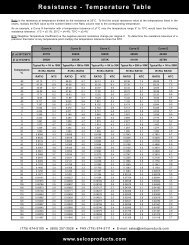
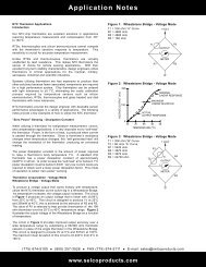
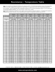
Application Notes<strong>NTC</strong> Thermistor ApplicationsIntroductionOur <strong>NTC</strong> chip thermistors are excellent solutions in applicationsrequiring temperature measurement and compensation from-50° to 150°C.RTDs, thermocouples and silicon semiconductors cannotcompete with the thermistor’s sensitive response totemperature. This sensitivity is crucial for accurate temperaturemeasurement.Unlike RTDs and thermocouples, thermistors are virtuallyunaffected by lead resistance. This makes <strong>NTC</strong> thermistorsthe sensor of choice for remote sensing applications. Withtheir excellent long term stability characteristics, designengineers utilize thermistors in critical applications for themedical, military, aerospace, industrial and scientific industries.Systems utilizing thermistors are less expensive to producethan other solutions because fewer associated componentsare required for a high performance system. Chip thermistorscan be ordered with tight tolerances to ±0.05°C, eliminatingthe costly calibration process required by temperature sensorssuch as silicon semiconductors, RTDs, thermocouples andglass beaded and disk thermistors with loose tolerances.<strong>NTC</strong> thermistors provide the design engineer with desirablesensor performance advantages in a variety of applications.The following notes provide a few examples of how to utilizethe <strong>NTC</strong> thermistor.“Zero Power” Sensing - Dissipation ConstantWhen utilizing a thermistor for temperature measurement,control, and compensation applications, it is very importantnot to “self-heat” the thermistor. Power, in the form of heat,is produced when current is passed through the thermistor.Since a thermistor’s resistance changes when temperaturechanges, this “self generated heat” will change the resistanceof the thermistor, producing an erroneous reading.The power dissipation constant is the amount of powerrequired to raise a thermistor’s body temperature 1°C. Astandard chip thermistor has a power dissipation constant ofapproximately 2mW/°C in still air. In order to keep the “selfheat”error below 0.1°C power dissipation must be below0.2mW. Very low current levels are required to obtain sucha lower power dissipation factor. This mode of operation iscalled “zero power” sensing.Thermistor Linearization - Voltage ModeWheatstone Bridge - Voltage ModeTo produce a voltage output that varies linearly withtemperature, utilize the <strong>NTC</strong> thermistor as the active leg ina Wheatstone Bridge. As temperature increases, the voltageoutput increases. The circuit in Figure 1 produces an outputvoltage that is linear with ±0.06°C from 25°C to 45°C. Thiscircuit is designed to produce 1V at 25°C and 200mWat 45°C; this is achieved by the selection of R2 and R3.The value of R1 is selected to best provide linearization ofthe 10K ohm thermistor over the 25°C to 45°C temperaturerange.Figure 2 illustrates the output voltage of the WheatstoneBridge as a function of temperature.The circuit in Figure 3 provides improved output accuracyover a wide temperature range by substituting a 6K/30K ohmthermistor network in place of the single thermistor in theWheatstone Bridge. This circuit is designed to provide 0V at0°C and 537mV at 100°C. The maximum linear deviation ofthis circuit is ±0.234°C from 0°C to 100°C.Figure 1: Wheatstone Bridge - Voltage ModeT1 = 10K ohm “A” CurveR1 = 4980 ohmR2 = 4980 ohmR3 = 10K ohmT1R11 VOLTOUTPUT+ -METERFigure 2: Wheatstone Bridge - Voltage ModeVOLTAGE OUTPUT (mV)20010002530 35 40 45OTEMPERATURE ( C)MAXIMUMLINEAR DEVIATIONACTUALOUTPUT RESPONSER3R2NOMINALLINEAR RESPONSEFigure 3: Wheatstone Bridge - Voltage ModeT1 = 30K ohm “B” CurveT2 = 6K ohm “A” CurveR1 = 5420 ohmR2 = 3970 ohmR3 = 3970 ohmR4 = 24720 ohmT2R1R21 VOLTT1OUTPUT+ -METERR4R3(714) 917-1333 (800) 257-3526 FAX (714) 917-1355 E-mail: sales@selcoproducts.comwww.selcoproducts.com
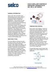
Application NotesThermistor LinearizationOperational Amplifier - Resistance ModeA linear voltage output that varies with temperature canalso be produced by utilizing an operational amplifier and alinearized thermistor network as illustrated in Figure 4. Thevoltage output decreases linearly as temperature increases.This circuit may be calibrated by adjusting R3 for an outputvoltage of 200mW at 25°C and 0V at 45°C.Temperature Measurement and ControlDigital ThermometerThe most common application for the <strong>NTC</strong> thermistoris temperature measurement. Accurate temperaturemeasurement can easily be accomplished by interfacing aWheatstone Bridge, 6K/30K ohm thermistor network and adigital voltmeter integrated circuit as illustrated in Figure 5.The IC consist of an analog to digital converter with built-in3-1/2 digit LCD driver providing resolution of 0.1°C. Usingthe 6K/30K ohm thermistor network makes it possible toachieve an overall system accuracy of ±0.4°C from 0°C to100°C. This digital thermometer can easily be interfacedwith additional circuitry to provide a temperature controlcircuit with a digital display.Micro Controller SystemThe advent of low cost micro controllers used with precisioninterchangeable <strong>NTC</strong> thermistors, provides the designengineer with unlimited design possibilities for temperaturemeasurement and control systems. These systemsare relatively inexpensive to produce yet offer very hightemperature accuracy and various software controlledoutputs.For example, a micro controller system utilizing remotethermistor sensors can monitor and control the temperaturein several locations in an office building. For this case, themicro controller is comprised of a built-in microprocessor,analog to digital converter, RAM and several digitalinputs/outputs. The complete system Figure 6 utilizes themicro controller, multiplexer, EPROM, digital display, keypadand display driver.The micro controller is programmed in assembler language.The temperature measurement is calculated within the microcontroller using the resistance versus temperature algorithmand the a, b and c, constants for the specific thermistorresistance and curve material. Refer to the SteinhartEquation on page 5. An alternative method to convert thethermistor resistance to temperature is to program a “lookup”table in EPROM. After programming, the micro controllertells the multiplexer to send back temperature data from aparticular zone (room in the office building) and converts theresistance of the thermistor into a temperature reading.The micro controller can then turn on or off the heating or airconditioning systems in a specific zone.The thermistor/micro controller system can be used forsecurity, temperature control, monitoring activities and manyother applications. The possibilities are endless.Figure 4: Linearization - Resistance ModeT1 = 10K ohm “A” CurveR1 = 4980 ohmR2 = 5K ohmR3 = 10K ohm potentiometerR3Figure 5: Digital ThermometerR7 = 1.50K ohmR8 = 100K ohmR9 = 470K ohmR10 = 15K ohmC1 = 100 pFC2 = 0.22C4 = 0.1T1T2R2R2R4R5R6R7R10R3C4R8R2C140 39 38363433Figure 6: Micro Controller SystemTHERMISTORZONE 1THERMISTORZONE 2THERMISTORZONE 3THERMISTORZONE 4THERMISTORZONE 5THERMISTORZONE 6MULTI-PLEXER313036A/DINPUTKEYPAD-+1R1T1R9C232 26DISPLAY70 OCDISPLAY DRIVERMICROCONTROLLEREPROMC329 28 272320222521+9VS1HEAT/ACZONE1HEAT/ACZONE 2HEAT/ACZONE 3HEAT/ACZONE 4HEAT/ACZONE 5HEAT/ACZONE 6TOLCD(714) 917-1333 (800) 257-3526 FAX (714) 917-1355 E-mail: sales@selcoproducts.comwww.selcoproducts.com
Application NotesTemperature Compensation<strong>NTC</strong> thermistors can be used to compensate for thetemperature coefficient response of various componentssuch as crystal oscillators, mechanical meters and infraredLEDs. A thermistor/ resistor network Figure 7 is placed inseries with a PTC component requiring compensation. Theresistor values are selected to provide the proper <strong>NTC</strong> slopeto offset the PTC component. The net effect is a constantcircuit response that is independent of temperature.Figure 7: Temperature CompensationT1R1R2COPPER COILMETERRESPONSEMETER CIRCUITRESPONSETEMPERATUREPTC COMPONENTRESPONSE<strong>NTC</strong> THERMISTORNETWORK“Self-Heat” Sensing ApplicationsTo “self-heat” a thermistor, it must be subjected to powerlevels that raise the thermistor’s body temperature abovethe environmental surroundings. Self-heat applicationsinclude the sensing of liquid and air level and flow rates.This application is dependent on the fact that the environmentsurrounding a thermistor directly affects the amount of powerthe thermistor can dissipate. For example, submerged inliquid, a thermistor can typically dissipate 500% to 600%more power than it can air.Therefore, a thermistor being “self-heated” in air is able todissipate much more power when transferred to a fluidenvironment. This increase in power dissipation generatesa significant increase in resistance. It is this change inresistance, which makes it possible to sense the fluid level.A simple liquid level control system can be designed byputting a thermistor in series with a coil Figure 8, whichoperates a valve that releases the liquid in the tank. Thethermistor is placed in the tank and operated in a “self-heat”mode.In air, the thermistor’s resistance is low and allows enoughcurrent flow to energize the relay coil and keep the relaycontact closed. When the fluid level in the tank surroundsthe the thermistor, its resistance increases and de-energizesthe relay, which opens a valve and releases the fluid. As thefluid is released from the tank, the thermistor’s resistancedecreases and the relay coil energizes and closes the valve.Fuel injection in automobiles utilize the thermistor in the“self-heat” mode in order to properly control the air/fuelmixture. Forced air heaters may use the <strong>NTC</strong> thermistorin the “self-heat” mode in order to maintain proper air flowcharacteristics. This technology is utilized to monitor theflow rate and level of air and fluids in a variety of applications.Figure 8: Self-Heat ApplicationsT1VALVERELAYCOIL(714) 917-1333 (800) 257-3526 FAX (714) 917-1355 E-mail: sales@selcoproducts.comwww.selcoproducts.com