
You also want an ePaper? Increase the reach of your titles
YUMPU automatically turns print PDFs into web optimized ePapers that Google loves.
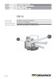
DEUTSCHENGLISHFRANÇAISITALIANO3152739BETRIEBSANLEITUNG UND SICHERHEITSVORSCHRIFTENOPERATINGAND SAFETY INSTRUCTIONSMODE D‘EMPLOI ET DE SÉCURITÉISTRUZIONI PER L‘USO E DI SICUREZZACM 60Ab Serie-Nr. 11'000From serie no 11'000A partir du no de série 11'000A partire dal no di serie 11'000Handgerät zum Umreifen mit KunststoffbandHand tool for plastic strappingAppareil pour le cerclage par bande plastiqueApparecchio per reggiare con reggetta di plasticaVor dem Gebrauch desGerätes die Betriebsanleitungaufmerksamlesen.Before using the tool,read the operatinginstructions carefully.Avant l’utilisation del’appareil, consultezsoigneusement le moded’emploi.Prima d’utilizzarel’apparecchio, leggereattentamante le istruzioniper l’uso.01.05/WE<strong>ORGAPACK</strong>
<strong>ORGAPACK</strong> CM 60TABLE OF CONTENTSPage1 Technical data 152 General information 162.1 Information on environmentalprotection 162.2 Cleaning the tool 163 Safety instructions 174 Description 184.1 Design 184.2 Function 185 Operating the tool 195.1 Refilling seals 195.2 Operating the tool 196 Preventive and corrective maintenance 216.1 Adjusting strap tension 216.2 Setting cut-off depth 216.3 Replacing cutter knife 217 Parts list 22Explosion drawing CM 60 25Explosion drawing CM 60 DA 261 TECHNICAL DATAWeight3.8 kg (8.4 lbs)Dimensions L = 370 mm (14.5")W = 160 mm (6")H = 250 mm (10")Strap tension 0–1200 N, fully variableSealingwith sealsSeal magazine for 40 sealsPLASTIC STRAPStrap quality Polypropylene PPPolyester PETStrap width 12–13 mm ( 1 / 2")Strap thickness Polypropylene 0.40–0.63 mm(.016"–.025")Polyester 0.40–0.63 mm(.016"–.025")SEALMatching seal CCP 48101.05/WE 15
<strong>ORGAPACK</strong> CM 602 GENERAL INFORMATIONThese operating instructions are intended to simplifyfamiliarisation with the strapping tool and the ways inwhich it may be used for the intended purpose. Theoperating instructions contain important informationconcerning the safe, proper and efficient use of thestrapping tool. Compliance with the instructions willhelp to avoid danger, reduce repairs and stoppagesand increase the reliability and service life of the strappingtool.The operating instructions must always be available atthe place of operation of the strapping tool. They mustbe read and observed by all persons concerned withwork on the strapping tool. This work specificallyincludes operation, refilling of operating material, faultelimination and maintenance.In addition to the operating instructions and the regulationsfor accident prevention effective in the country ofuse and place of application, the recognised technicalregulations for safety and proper working must also beobserved.CAUTION!Used where there isdanger to life and health.WARNING!Used for danger whichcan cause materialdamage.NOTE!Used for general informationand informationwhich, if not followed,can cause faults in theoperating sequence.2.1 INFORMATION ON ENVIRONMENTALPROTECTIONThis tool is manufactured without any physical orchemical substances which could be dangerous tohealth. For disposal of all the parts, the governmentalinstructions must be observed.2.2 CLEANING THE TOOLThe tool should be regulary cleaned and lubricated.Any particles of straps sticking in the tension wheelcan be cleaned with the supplied steel brush.Little oil between the jaws and on the sliding surfacesof the aluminium housing is sufficient.1601.05/WE
<strong>ORGAPACK</strong> CM 603 SAFETY INSTRUCTIONSjklsfjklsdjšlksdfjkljkljsdllkjjkljsdfkljjklkjkljsdafjasdfjklkjjkljkljksldafkjkljklšjkljklkljsdafjlkjjkljjkljklkljljlkInform yourself!Read the operatinginstructions carefully.Use for the intended purposeThe tool is intended for strapping packages, palletloads etc.This tool was designed and manufactured for safehandling during the strapping operation.Protect yourself!When operating the tool,wear eye, face and handprotection (cut-proofgloves).Warning:Strap will snapforward!When cutting the strap,hold the upper portionand stand safely awayfrom the strap.Caution:The lower strap will snapforward.Warning:Strap could break!Do not stand in line withthe strap while it istensioned. The strapcould break!Caution:Danger of squeezing!Do not put your fingersinto the tension wheelarea.Caution:Only strap packedgoods!Do not put hands or otherparts of the body betweenthe strap and thepackage during the strappingprocess.The tool processes plastic straps only (polypropyleneand polyester).Possible misuseThe use of steel straps is not possible.Original<strong>ORGAPACK</strong>Original <strong>ORGAPACK</strong>seals must be usedexlusively.Original<strong>ORGAPACK</strong>Original <strong>ORGAPACK</strong>spare parts must beused exclusively!Not using original spareparts will dissolve thewarranty and the liability.01.05/WE 17
<strong>ORGAPACK</strong> CM 604 DESCRIPTION4.1 DESIGN9101 21 Carrying handle2 Sealing lever3 Handle4 Rocker lever5 Tension wheel6 Tension shoe7 Seal support8 Seal magazine9 Tension lever10 Seal weight block873456Fig. 14.2 FUNCTION– Cramping of strap over tension shoe (2/5) throughtoothed plate (2/6).– Tensioning by feed wheel principle (2/4).– Feeding of seal (2/1) out of seal magazine.– Sealing by notching (2/2) the seal.– Strap cut with knife (2/3).2 314556Fig. 21801.05/WE
<strong>ORGAPACK</strong> CM 605 OPERATING INSTRUCTIONS5.1 REFILLING SEALS– Pull out and fold back the seal weight block. Refillthe magazine with a new stack of seals, so that theshort part of the seals looks towards the open side ofthe magazine. Replace the seal weight block on topon the seals.– If the sealing device is empty, the sealing lever mustbe operated once, so that one seal get pushed intothe sealing mechanism.Fig. 35.2 OPERATING THE TOOL– Place strap firm around the package and hold it withthe left hand so that the lower strap start (4/1) isapprox. 20 cm (8") away from the hand. The indexfinger lies between the two straps.– Grip the tool with the right hand and lift the rockerlever towards the handle.– Slide both straps into the tool until the stop isreached, the lower strap start must be below theseal magazine. Guide the straps with the indexfinger so that the tension shoe is positioned betweenthe two straps.– Release the rocker lever.1Fig. 401.05/WE 19
<strong>ORGAPACK</strong> CM 60– Hold the tool with the left hand by the carryinghandle and move the tension lever with the right handback- and forward until the desired strap tension isreached.Adjustment of maximum strap tension, seeChapter 6.1 (only CM 60 with frictionclutch).Fig. 5– Grip the tool on the handle with the right hand andpress the sealing lever with the left hand forward untilthe stop is reached.– Pull back the lever.Fig. 6– Pull the rocker lever towards the handle with the righthand and swivel the tool away to the right of thestrap.Check of sealTo obtain the maximum seal efficiency, the notcheshave to be cut properly into the seal.An incorrect sealed strapping cannot securethe package and can thus lead to injuries.Fig. 72001.05/WE
<strong>ORGAPACK</strong> CM 606 PREVENTIVE AND CORRECTIVE MAINTENANCE+6.1 ADJUSTING STRAP TENSION–14The maximum strap tension is determinedby the adjustment of the friction clutch.For this reason a fork wrench is supplied.171– Block the tension shaft with a fork wrench (SW 11).With other fork wrench (SW 17) adjust the nut (8/1).– Turning the nut in clockwise direction the straptension is increased. Turning the nut in counterclockwisedirection the strap tension is reduced.Fig. 8Best results are achived by adjusting theclutch to the maximum tension for thepackage being strapped. But not tight that the tensionwheel will turn over or the strap breaks.Do not oil the friction clutch!6.2 SETTING CUT-OFF DEPTHWhen correctly adjusted the upper strap willbe cut through without damaging the lowerstrap.– Turning the screw (9/1) in clockwise direction, thecutting will be increased, turning counter-clockwisethe cut-off depth is reduced.1Fig. 91 2 3 46.3 REPLACING CUTTER KNIFERemoval– Remove seals from seal magazine.– Remove two screws (10/5).– Remove two screws (10/4).– Remove seal housing (10/1) and seal guide (10/9).– Remove jaw package (10/2).– Remove two counter sunk screws (10/3).– Remove two retaining rings (10/6) and remove guidelink (10/7).– Remove and replace cutter knife (10/8).Fig. 1098765Installation– Install the parts in reverse order.When installing jaw package, observe that the torsionspring (page 25, pos. 99) is positioned underneaththe counter sunk screw.01.05/WE 21
<strong>ORGAPACK</strong> CM 607 PARTS LIST CM 60 / CM 60 DA 2172.600.000/1.2When ordering please indicate part number and quantity Explosion drawing see page 25, 26* Recommended spare partsPos. Part no Part name Quantity1 2172.600.046 Base plate 1(incl. pos. 3)23 1820.020.140 Bushing 445 2172.600.023 Holding plug 16 1911.005.088 Cylinder screw, M 5 x 8 1*7 2172.700.003 Strap guide 18 2172.600.017 Cutter plate 19 1927.600.620 O-Ring, ø 6 x ø 2 110 1911.905.082 Counter sunk screw, M 5 x 8 211 1910.505.062 Set screw, M 5 x 6 112 1820.040.014 Tension plug 113 1921.403.241 Spiral pin, ø 3 x 24 2* 14 1820.040.040 Tension plate 115 1910.405.042 Set screw, M 5 x 4 116 1922.108.253 Ridged pin, ø 8 x 24 11718 1917.904.258 Counter sunk washer, M 4 119222021 2172.600.004 Rocker (incl. Pos. 3) 12223 1820.030.267 Shaft 124 1820.020.051 Rocker roll 125 1920.104.072 Retaining ring, ø 4 226 1933.716.160 Needle bearing 227 1926.501.160 Free-wheel needle bearing 228 1911.005.168 Cylinder screw, M 5 x 16 229 1820.030.330 Rocker shaft 130 2172.600.029 Tension shaft 131 1934.330.120 Thrust bearing 132 1820.040.041 Tension wheel 133* 34 1830.000.262 Clutch disc 135 1921.404.181 Spiral pin, ø 4 x 18 136 1830.000.261 Carrier 137 1925.210.122 Saucer spring ø 12.2 638 1820.020.163 Nut 139 1820.080.026 Tension lever complete 1(incl. pos. 41)4041 1820.080.051 Knob black 242 1921.406.241 Spiral pin, ø 6 x 24 143 1917.401.165 Spacer, ø 16/28 x 0.5 144 1920.216.102 External retaining ring, ø 16 145 1820.030.263 Bolt 146 1820.010.052 Tension spring 1474849Pos. Part no Part name Quantity50515253545556 2172.600.003 Handle part 157 1820.030.271 Shaft 158 2172.600.018 Lifting segment 159 1920.106.072 Retaining ring, ø 6 460 1921.908.542 Roll pin, ø 8 x 60 161 1820.020.200 Bushing 16263646566 1911.906.222 Counter sunk screw, M 6 x 25 367 1911.704.087 Counter sunk screw, M 4 x 8 268697071727374757677 2172.600.005 Handle 178 2172.600.021 Guide roller holder complete 17980 1820.020.054 Guide roller 281 1820.030.059 Rivet bolt 282 1911.005.128 Cylinder screw, M 5 x 12 783848586878889909192 2172.600.007 Guide link rear 19394 2172.600.006 Guide link front (incl. pos. 95) 195 1820.020.193 Bushing 196 2172.600.024 Sealer shaft 197 2172.600.058 Pignon 198 1820.020.159 Bushing 2* 99 1820.010.141 Torsion spring 1100 2172.600.016 Cam complete 1(incl. 80, 81)01.05/WE
<strong>ORGAPACK</strong> CM 60Pos. Part no Part name Quantity Pos. Part no Part name Quantity101102 1820.020.166 Roller 1103 2172.600.009 Bearing left 1104 2172.600.008 Bearing right 1105106107108109110 2172.600.013 Pusher 1111 2172.600.035 Link right 2112 2172.600.036 Link left 2113 1820.020.157 Jaw roller 2114 1820.030.266 Bolt 2115 1820.030.268 Bolt 2116 1920.208.082 Retaining ring 4* 117 1820.010.058 Compression spring 1118 2172.100.065 Key 1* 119 2172.100.064 Cutter knife 1120 2172.100.066 Shim 1* 121 2172.600.011 Cutter jaw left 1* 122 2172.600.012 Cutter jaw right 1123 2172.600.010 Seal retainer 1124 1820.020.188 Roller 2125126 2172.600.031 Jaw left 1127 2172.600.032 Jaw left 2128129 2172.600.033 Jaw right 1130 2172.600.034 Jaw right 2131132 2172.640.001 Counter support 2132 2172.640.005 Counter support for 0.6 mm 2133134 1820.030.270 Bolt 2135 1911.905.102 Counter sunk screw, M 5 x 10 9136 1820.080.044 Sealing lever complete 1(incl. pos. 41)137138 1911.005.258 Cylinder screw, M 5 x 25 1139 1916.305.052 Lock nut, M 5 4140141 1820.030.017 Cylinder screw 1142 1916.308.082 Lock nut, M 8 1143 1917.803.086 Washer, M 8 1144145146147148149150 2172.600.030 Seal housing 1(incl. Pos. 153)151152153 1922.104.123 Ridged pin, ø 4 x 12 1154 2172.640.003 Seal guide left 1155 1911.905.162 Counter sunk screw, M 5 x 16 2156157158 1820.020.162 Bushing 1159 2172.600.028 Trigger 1160 1917.803.056 Washer, M 5 3161 1911.505.169 Hexagon screw, M 5 x 16 1162163 1820.010.032 Tension spring 1164165 1923.501.120 Cotter pin, ø 2 x 12 1* 166 1830.000.057 Leaf spring 1167 1912.503.087 Pan head screw, M 3 x 8 1168 1830.000.058 Spring tensioner 1169 2172.640.004 Seal weight block, blue 1170 2172.600.026 Lever 1171 2172.600.027 Trigger 1172 1820.020.168 Bushing 1173174175176177 1820.030.269 Shaft 1* 178 1820.010.139 Torsion spring 1179 1911.105.502 Cylinder screw, M 5 x 50 1* 180 1820.010.138 Twin stud torsion spring 1181 2172.600.022 Seal feed lever 1182 1820.020.156 Spacer bushing short 1183 1820.020.155 Spacer bushing long 1184 2172.600.037 Seal guide right 1185186 1911.006.208 Cylinder screw, M 6 x 20 2187188189190191192193 1821.090.003 Name plate 1194195 1990.101.017 Fork wrench SW 17 1196 1990.199.001 Wire brush 1197198199200Parts for direct drive (DA)240 1820.080.035 Tension lever complete 1(incl. pos. 41)241242 1830.000.289 Stop 1243 1921.403.141 Spiral pin, ø 3 x 14 2244245246 1921.405.241 Spiral pin, ø 5 x 24 1247 1820.030.329 Bolt 101.05/WE 23
<strong>ORGAPACK</strong> CM 60Pos. Part no Part name Quantity248 1920.209.102 External retaining ring ø 9 2249 1820.050.052 Tension pawl 1250 1820.010.061 Compression spring 1251 1820.040.060 Blocking wheel 1252253254255256257258259260 1830.000.062 Key 2261 2173.900.008 Tension shaft 1262 1820.040.047 Tension wheel 1263 1820.020.194 Spacer bushing 1264 1920.112.132 Retaining ring, ø 12 1Parts for steel base plate2172.600.059 Base plate 11911.906.258 Counter sunk screw, M 6 x 25 11916.006.088 Nut, M 8 11911.905.162 Counter sunk screw, M 5 x 16 11911.005.128 Cylinder screw, M 5 x 12 12401.05/WE
25a)Loctite 222 b) Loctite 243 d) Loctite 480 CM 60 2172.600.000/3 18.04.02 Ba/hp01.05/WE
26a)Loctite 222 b) Loctite 243 d) Loctite 480DA = Direct driveCM 60 DA 2172.602.000/4 18.04.02 Ba/hp01.05/WE