Robinair 12134B - NY Tech Supply
Robinair 12134B - NY Tech Supply
Robinair 12134B - NY Tech Supply
- No tags were found...
Create successful ePaper yourself
Turn your PDF publications into a flip-book with our unique Google optimized e-Paper software.
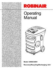
○ ○ ○ ○ ○ ○ ○ ○ ○ ○ ○ ○ ○ ○ ○ ○ ○ ○ ○ ○ ○ ○ ○ ○ ○ ○ ○ ○ ○ ○ ○ ○ ○ ○ ○ ○ ○ ○ ○ ○ ○ ○ ○ ○ ○ ○ ○ ○ ○ ○ ○ ○ ○ ○ ○ ○ ○ ○ ○ ○ ○ ○ ○ ○ ○ ○ ○ ○ ○ ○ ○ ○ ○ ○ ○ ○○OperatingManualSeries <strong>12134B</strong>Recovery/Recycling/Recharging Unitfor R-12 and R-134a
LISTED80S2Design Certified byUnderwriters LaboratoriesInc., ® to meet SAE J1770for recycling R-12 andR-134a using commonrefrigerant circuitsRefrigerant Recovery,Recycling, and Recharging StationWARNINGSeries: <strong>12134B</strong>Refrigerants: R-12 and R-134aPRESSURIZED TANK CONTAINS LIQUID REFRIGERANT. OVERFILLING OF THE TANK MAY CAUSE VIOLENTEXPLOSION AND POSSIBLE INJURY OR DEATH. Safety devices require the use of only authorized refillable refrigeranttanks. Refer to the instruction manual for tank specifications and ordering information. Do not recover refrigerantsinto a non-refillable storage container! Federal regulations require refrigerant to be transported only in containers meetingDOT spec. 4BW or DOT spec. 4BA.ALL HOSES MAY CONTAIN LIQUID REFRIGERANT UNDER PRESSURE. Contact with refrigerant may cause injury.Wear proper protective equipment, including safety goggles. Disconnect hoses with extreme caution.HIGH VOLTAGE ELECTRICITY INSIDE PANELS. RISK OF ELECTRICAL SHOCK. Disconnect power before servicingunit. Refer to the instruction manual.REDUCE THE RISK OF FIRE. Avoid the use of an extension cord becausethe extension cord may overheat. If an extension cord must be used, it must be No. 14 AWG minimum and as short aspossible. Do not use this equipment in the vicinity of spilled or open containers of gasoline or other flammable substances.Use this equipment in locations with mechanical ventilation that provides at least four air changes per hour or locate theequipment at least 18 inches above the floor.Make certain that all safety devices are functioning properly before operating the unit. Before operating, read and followthe instructions and warnings in the operating manual.CAUTION: SHOULD BE OPERATED BY QUALIFIED PERSONNEL. Operator must be familiar with air conditioningand refrigeration systems, refrigerants and the dangers of pressurized components.Use this unit with R-12 or R-134a systems only. This equipment is not designed for any other purpose thanrecovering, recycling or recharging refrigerants! Do not mix refrigerant types!ATTENTION!Ce réservoir sous pression contient du frigorigène liquide. S’il est surchargé, ce réservoir peut exploser et causer desblessures ou la mort.ATTENTION. Débrancher avant la maintenance.ATTENTION. Pour réduire les risques d’incendie, ne pas utiliser de cordon prolongateur de section inférieure à 14 AWGde facon à éviter la surchauffe du cordon.ATTENTION. Utiliser seulement du frigorigène R-12 ou R-134a.OPERATING NOTES1. Press SHIFT/RESET until the “CLR” message appears in the display.2. Press HOLD/CONT. The unit will begin clearing refrigerant. This takes approximately 20 minutes.3. When the changeover is complete, the “CPL” message will be displayed.4. Move the refrigerant selector switch to the appropriate refrigerant type (R-12 or R-134a).R-134a WARNINGS!Cross-contamination with other refrigerant types will cause severe damage to the A/C system and to service tools andequipment. Do not mix refrigerant types through a system or in the same container!Avoid breathing A/C refrigerant and lubricant vapor or mist. Exposure may irritate eyes, nose and throat. To removeR-134a from the A/C system, use service equipment certified to meet the requirements of SAE J1770 (R-134a recyclingequipment). If accidental system discharge occurs, ventilate work area before resuming service.HFC-134a service equipment or vehicle A/C systems should not be pressure tested or leak tested with compressed air.Some mixtures of air/HFC-134a have been shown to be combustible at elevated pressures. These mixtures are potentiallydangerous and may result in fire or explosion causing injury or property damage.Additional health and safety information may be obtained from refrigerant and lubricant manufacturers.
IntroductionThis manual contains important safety procedures concerning the operation,use and maintenance of this product. Failure to follow the instructionscontained in this manual may result in serious injury. If you are unable tounderstand any of the contents of this manual, please bring it to the attentionof your supervisor. Do not operate this equipment unless you have read andunderstood the contents of this manual.TABLE OF CONTENTSIntroduction ................................................................................................ 1Glossary of Terms ....................................................................................... 2Operating Guidelines................................................................................... 3Set Up Instructions ..................................................................................... 8Operating Instructions .............................................................................. 21Operating Overview .................................................................................. 33Maintenance Instructions .......................................................................... 36Troubleshooting Tips ................................................................................ 43Replacement Parts List ............................................................................. 50Flow Diagram ........................................................................................... 52Wiring Diagram......................................................................................... 53Warranty ................................................................................................... 54See Index (55) for a complete listing of all procedures and diagrams.Series <strong>12134B</strong> Recovery/Recycling/Recharging Unit for R-12 and R-134a1
Operating GuidelinesRECYCLE1RECOVER0413-112 34 5 67 8 90SHIFTRESETDiagram of KeypadFILTERCHG.HOLDCONT.VACUUMENTERKEYPAD FUNCTIONSIn addition to the number keys, the keypad contains specialkeys that accomplish specific operating functions.• RECYCLE — Activates the recycling sequence when pressedat the same time as the SHIFT/RESET key.• RECOVER — Activates the recovery sequence.• SHIFT/RESET — Accesses the PROGRAM mode and movesyou from one program function to the next.• FILTER — When pressed at the same time as the SHIFT/RESET key, automatically recovers and evacuates from thefilter and low side of the unit so you can change the filter.• CHG — Automatically charges the A/C system with theprogrammed amount of refrigerant.• HOLD/CONT — Interrupts the AUTOMATIC cycle (HOLD),then resumes functions (CONT). Press once for HOLD, andagain for CONT (continue).• VACUUM — Activates the vacuum and automatic recyclingsequence.• ENTER — Enters programmed data into the unit memory.4© 1998 <strong>Robinair</strong>, SPX Corporation
Operating GuidelinesDIGITAL DISPLAY MESSAGESThis section explains the messages shown on the digital display,which is illustrated below.ACBDDiagram of Digital DisplaySegment A — Indicates the current operating mode:PROGRAM — The unit is in the PROGRAM mode, whichallows you to program vacuum time and refrigerant weightor to review the existing program.HOLD — This mode is used to change a refrigerant tank orto interrupt the vacuum/charging/recovery cycles.AUTOMATIC — Indicates that the unit is running in a givencycle and will automatically stop when the cycle is complete.Segment B — Indicates that the unit is either evacuating the A/C system or recovering, recycling, or recharging refrigerant orthat the unit is ready to be programmed for one of thesefunctions:(See the chart below for a quick reference of these segments.)Use chart as a quick reference for interpreting Segment B messages.VACUUM + PROGRAM = Program unit for vacuumVACUUM + AUTOMATIC = Vacuum pump is runningVACUUM + HOLD = Interrupted vacuum cycleRECYCLE + AUTOMATIC = Unit is recycling refrigerantCHARGE + PROGRAM = Program unit for chargeCHARGE + AUTOMATIC = Unit is charging A/C systemCHARGE + HOLD = Interrupted charging cycleRECOVER + AUTOMATIC = Unit is recovering refrigerantSeries <strong>12134B</strong> Recovery/Recycling/Recharging Unit for R-12 and R-134a5
Operating GuidelinesVACUUM• With PROGRAM, indicates that the unit is ready to beprogrammedfor vacuum.• With AUTOMATIC, indicates that the vacuum pump isrunning; the number displayed counts down in minutes and seconds,showing the amount of time remaining.• With HOLD, indicates that HOLD/CONT was pressed tointerrupt the vacuum cycle.RECYCLE• With AUTOMATIC, indicates the unit is recycling refrigerant fromthe tank.CHARGE• With PROGRAM, indicates that the unit is ready to beprogrammedfor the amount of refrigerant to be charged into the A/C system; onthe keypad enter the charge in pounds and hundredths of a pound.• With AUTOMATIC, indicates the unit is charging refrigerant into theA/C system; the number shown on the digital display counts down,showing the remaining amount of refrigerant to be dispensed.• With HOLD, indicates that HOLD/CONT was pressed tointerrupt the charging cycle; the number shown on the digital displayis the amount of refrigerant remaining to be charged into the A/Csystem; to continue charging, press HOLD/ CONT again.RECOVER• With AUTOMATIC, indicates the unit is recovering refrigerant fromthe A/C system and shows the amount of refrigerant recovered inpounds.OIL(OUNCES)• Lights up as a reminder to drain the oil separator aftereach job.Segment C — Shows a number or a coded error message on the digitaldisplay that indicates the unit’s operating status or any specific problems.See “Troubleshooting Tips” for a list of error codes and messages.Segment D — Indicates that refrigerant is low — approximately 6pounds of refrigerant is left in the tank. Either replace the tank or addrefrigerant as described in “Adding Refrigerant to the Tank.”6© 1998 <strong>Robinair</strong>, SPX Corporation
Operating GuidelinesUSING MANUAL DIAGNOSTICSWARNINGBe sure to discharge AC system pressure before performing anymanual diagnostics or be sure all refrigerant has been recoveredfrom the AC system before performing any diagnostics.This unit’s manual diagnostics mode is easily accessible throughthe keypad.1. Press SHIFT/RESET and ENTER at the same time. The display willshow the message “FUNC.”2. Press the following keys to perform these functions:Press “1” — Starts the vacuum pump to begin evacuation. Tointerrupt evacuation, press HOLD/CONT. To resume operation, pressHOLD/CONT again.Press “2” — Begins the transfer of refrigerant. The “ADD” messagedisplays momentarily, then the display shows the amount ofrefrigerant transferred. Press HOLD/CONT at any time to interruptthe transfer, then press HOLD/CONT again to continue.Press “3” — Displays the total amount of refrigerant recovered.Each time recovery is completed, the latest amount is added to theexisting total. To clear the internal counter, press SHIFT/RESET andENTER at the same time while the total is being displayed. Themaximum amount recorded is 9,999 pounds of refrigerant.Press “5” — All display segments light up.Press “6” — Automatically sets the scale to "0" then displays theapproximate weight added to the scale.Press “7” — Displays the approximate weight of refrigerantcontained in the tank.Press “9” — Allows access to the scale calibration feature.Press “0” — Automatically switches from pounds to kilograms.Press HOLD — Performs a manual air purge.3. Press SHIFT/RESET to return to the PROGRAM mode.Series <strong>12134B</strong> Recovery/Recycling/Recharging Unit for R-12 and R-134a7
Set Up InstructionsVapor ValveManifold BlockAssemblyInlet SolenoidAssemblyFan(behindcompressor)Liquid ValveManifold BypassSolenoidHigh SideDiversion SolenoidAir PurgeAssemblyCheck ValveSolenoidEqualizationSolenoidCompressorElectrical BoxFilterAccumulator/CondensorVacuum PumpOil DrainDiagram of Unit’s Components — Internal View8© 1998 <strong>Robinair</strong>, SPX Corporation
Set Up InstructionsR-12 / R-134aSwitchPowerReceptacleMain PowerSwitchR-134a High Side HoseR-134a Low Side HoseR-12High Side HoseR-12 Low SideHoseR-134a Tank Vapor PortR-134a Tank Liquid PortR-134a Tank Air PurgePortR-12 Tank Vapor PortR-12 Tank Liquid PortR-12 Tank Air PurgePortScale PlatformsR-134a R-12Diagram of Unit’s Components — Rear ViewSeries <strong>12134B</strong> Recovery/Recycling/Recharging Unit for R-12 and R-134a9
Set Up InstructionsR-12DisplayHigh Side ValveCLOSE VALVES WHEN OPERATING VEHICLEHIGHR-12134aCLOSEDOPENHIGHR-134aHigh Side ValveHigh Side GaugeOPENCLOSEDHigh Side GaugeLow Side ValveLOWCLOSEDOPENLOWLow Side ValveLow Side GaugeOPENCLOSEDLow Side GaugeRECYCLE1 2 3FILTERCHG.INST02224 5 6HOLDCONT.7 8 9VACUUMKeypadRECOVER0SHIFTRESETENTERDiagram of Control Panel and KeypadPREPARING THE VACUUM PUMPThe VacuMaster ® vacuum pump is shipped without oil in thereservoir. Before starting the unit, you must fill the pump withoil. Two 16-ounce (472 milliliters) bottles of oil are includedwith your unit.Oil Fill PortOilSightGlassOilFillLineOilDrainCapDiagram of Vacuum Pump Components10© 1998 <strong>Robinair</strong>, SPX Corporation
Set Up InstructionsBefore starting the set up procedures, open the oil drain valve and allowthe unit to depressurize.1. Plug the unit into a proper voltage outlet.CAUTION! Avoid the use of an extension cord. It may overheat.If you must use an extension cord, use No. 14 AWG minimum andkeep the length to 25 feet (7.6 meters) or less.2. Be sure the oil drain valve is closed.3. Turn on the unit. The display will flash the current position of therefrigerant switch.4. Before adding oil to the vacuum pump, be sure both sets of manifoldvalves are closed.5. Remove the access door from the front of the unit. Remove the blackplastic plug from the pump’s oil fill port. Attach the flexible spout andcap to the bottle of oil included with your unit (this makes it easier tofill the pump).6. Select the correct refrigerant switch position before pressing anykeys.7. Press SHIFT/RESET. The display shows the 15-minute vacuum defaulttime.8. Add six to eight ounces of vacuum pump oil to the pump(approximately half the bottle supplied with your unit).9. Press SHIFT/RESET and ENTER at the same time. When the displayshows the “Func” message, press “1” to start the vacuum pump.10. While the pump is running, pour oil into the pump’s oil fill port untilthe level of oil is even with the line on the pump reservoir sight glass.11. Press HOLD to stop the pump, then press SHIFT/RESET to return tothe program mode.12. Replace the black plug on the oil fill port. Replace the front accessdoor.See the “Maintenance Instructions” for step-by-step procedures forchanging the vacuum pump oil.IMPORTANT!Be sure the pump isrunning whenadding the rest of theoil to the pump. Donot overfill the pump.The approximate oilcharge is 13 ounces(384 milliliters).Series <strong>12134B</strong> Recovery/Recycling/Recharging Unit for R-12 and R-134a11
Set Up InstructionsSELECTING A MEASUREMENT UNITThe next step in setting up your unit is to select the unit of measure(either pounds or kilograms) to be used when operating the unit.1. Press SHIFT/RESET and ENTER at the same time.2. When the “Func” message appears on the display, press “0.” Thedisplay will indicate that a unit of measure has not been set.3. Press ENTER to toggle between the units of measure.4. When the desired unit of measure is displayed, press SHIFT/RESET.ENTER12© 1998 <strong>Robinair</strong>, SPX Corporation
Set Up InstructionsINSTALLING THE TANKAND PULLING A VACUUMWARNINGAlways wear safety goggles when working with refrigerant. Use onlyauthorized refillable refrigerant tanks. Read and follow all warnings atthe beginning of this manual before operating the unit.CAUTION! R-134a systems have special fittings (per SAEspecifications) to avoid cross-contamination with R-12 systems. Donot attempt to adapt your unit for any other refrigerant — systemfailure will result!R-134a TankYellow AirPurge HoseRed Vapor ValveRed Vapor HoseBlue Tank HoseBlue Liquid ValveR-12 TankBlue Liquid ValveBlue Tank HoseRed Vapor HoseRed Vapor ValveYellow AirPurge HoseIMPORTANT:Valves on tankmay not be asshown. Alwaysfollow markingson valve handle;Liquid (Blue),Vapor/Gas(Red).IMPORTANT:Attach the Quick-Seal ends of thehoses to thetanks.Attach the 45 ostandard fittingsto the unit. Thesefittings must beangled toward thecenter of the unit.Hoses must berouted betweenthe tanks. Accuracyof the scalesmay be affectedby hoses leaningon the tanks.Diagram of Tank InstallationSeries <strong>12134B</strong> Recovery/Recycling/Recharging Unit for R-12 and R-134a13
Set Up InstructionsR-12LOW SIDEVALVE OPENSHIFT/RESETINST0229ENTERINST0228SHIFT/RESETENTER134ALOW SIDEVALVE OPENBefore installing and pulling a vacuum on the tank, make sure all the 36 in.(91cm) hoses are attached to the back of the unit, as shown on theprevious page.1. A new tank comes with 5 to 10 psi of nitrogen gas to keep it cleanand dry during shipment. Purge its nitrogen charge by opening theGAS (vapor) valve on the tank. Vent the pressure to the atmosphere,then close the valve.2. Place the unit tanks on the scale platforms on the back of the unit.Securely tighten the thumbscrew on the platforms to hold the tanks inplace. Attach tank strap clips to unit tanks.CAUTION! Some tanks have slightly different valveconfigurations. Be sure to connect the red hose to the GAS(vapor) valve and connect the blue hose to the LIQUID valve.3. Connect the 36 inch (91 cm) yellow air purge hose to the low sideport on the unit and to the fitting on the unit tank.4. Connect the 36 inch (91 cm) red vapor hose on the unit to the GAS(vapor) valve on the unit tank.14© 1998 <strong>Robinair</strong>, SPX Corporation
Set Up Instructions5. Connect the 36 inch (91 cm) blue liquid hose to the LIQUID valve onthe tank.Before adding refrigerant, you must pull a vacuum on both the unit and thetank for five minutes to remove any air.6. Open both valves on the tank.7. Open the low side manifold valve on the control panel.8. Press SHIFT/RESET and ENTER at the same time. The display showsthe message “Func.”9. Press “1.” The vacuum pump starts and runs continuously.10. Let the pump run for a minimum of five minutes. A vacuum may thenbe pulled on the other refrigerant tank by changing the selectorswitch. Run a vacuum on this tank for a minimum of 5 minutes. Afterat least 5 minutes, set the selector switch on the required refrigeranttype. Press HOLD to stop the pump. Press SHIFT/RESET to return toPROGRAM mode.CAUTION! The procedure described in steps 1 through 10 isfor new tanks only. It should be done only on initial set-up or afterclearing cycle has been completed. Using this procedure forused tanks could damage the vacuum pump and/or allow crosscontaminationto occur.11. To maintain vacuum on the tank, close the low side valve on thecontrol panel. Disconnect the 36 inch (91 cm) yellow hose from thetank on the unit FIRST, before disconnecting this hose from the backof the unit. Disconnecting in this order will prevent vacuum loss fromthe unit tank.• To partially fill a tank during initial set up, see “Partially Filling ATank.”• To add refrigerant to the tank during normal operation, see “AddingRefrigerant to the Tank.”NOTE: Any time the refrigerant type is flashing on the display, therefrigerant selector switch may be changed.Series <strong>12134B</strong> Recovery/Recycling/Recharging Unit for R-12 and R-134a15
Set Up InstructionsR-134a or R-12Open Appropriate Valves For System Being ServicedINST0232SHIFT/RESETENTERDiagram of Control Panel When Adding RefrigerantR-12R-134aBlueTankHoseDisposableTank(inverted)Diagram of Disposable Tank Connections When Adding Refrigerant16© 1998 <strong>Robinair</strong>, SPX Corporation
ADDING REFRIGERANT TO THE TANKSet Up InstructionsCAUTION! R-134a systems have special fittings (per SAEspecifications) to avoid cross-contamination with R-12systems. Do not attempt to adapt this unit for any otherrefrigerant — system failure will result! Read and follow allwarnings given at the beginning of this manual.NOTE: Purchase only tanks of R-134a refrigerant that have 1/2 inch(1.2cm) Acme threads. This is necessary to match the hose fittings.1. Connect one end of the 36 inch (91 cm) yellow hose to the air purgeport on the back of the unit, then connect the other end to the airpurge fitting on the unit tank.2. Close the LIQUID valve on the unit tank, and disconnect the 36 inch(91 cm) blue liquid hose from the valve.3. When using R-12, connect the 6 inch (15.2 cm) yellow adapter to thesource tank first. Then connect the 36 inch (91cm) blue LIQUID hoseto the adapter.IMPORTANT!When setting up forboth types ofrefrigerant, aclearing process willhave to beperformed.IMPORTANT!The 96 inch (244 cm)red high side hoseand the 96 inch (244cm) blue low sidehose are not usedwhen addingrefrigerant to thetank.When using R-134a, connect the blue liquid hose directly to the blueLIQUID valve of the source tank. Disposable tanks have only onevalve and most must be turned upside down to transfer liquid. If youare using a disposable tank, follow the instructions on the side of thetank to obtain a liquid supply.4. Open the LIQUID valve on the source tank (there is only one valve ona non-refillable tank).CAUTION! Do not use the 96 inch (244 cm) blue low sidehose! The blue LIQUID hose is the blue hose attached to thetank’s LIQUID valve.5. Open the red GAS (vapor) valve on the unit tank.(continued)Series <strong>12134B</strong> Recovery/Recycling/Recharging Unit for R-12 and R-134a17
Set Up Instructions6. Press SHIFT/RESET and ENTER at the same time to access thediagnostic mode. The display shows the message “Func.”7. Press 2 to begin transferring refrigerant. The display shows the “Add”message for about two seconds, then shows the amount of refrigeranttransferred.8. Transfer stops automatically and the display shows the “CPL”message when the source tank is empty and has been pulled to apartial vacuum or the weight of refrigerant in the unit tank reaches 15pounds. The display toggles between “CPL” and the weight in thetank.Weight Example ** The display shows the weight ofrefrigerant added to the tank.This process takes about 45 minutes. You can interrupt it at any time bypressing HOLD/CONT once. Press HOLD/CONT again to resumeoperation. The transfer of new refrigerant is limited by weight to leavespace (about 10 pounds of refrigerant) in the unit tank for recoverypurposes.9. When using R-12, close the supply valve on the source tank, andcarefully disconnect the 36 inch (91 cm) blue liquid hose from the 6inch (15.2 cm) yellow adapter, if used; then remove the 6 inch (15.2cm) yellow adapter from the source tank.When using R-134a with a disposable tank, turn the tank rightside up, close its valve and carefully disconnect the 36 inch (91 cm)blue liquid hose.10. Reconnect the 36 inch (91 cm) blue liquid hose to the LIQUID valveon the unit tank, then open that tank’s LIQUID valve.11. Connect the 96 inch (244 cm) red high side hose to the unit’s highside port. You can also attach an oil injector to the unit’s low sideport. Oil injectors will not connect to the wrong ports.The R-12 oil injector has a ¼ inch flare connector; the R-134a oilinjector has a ½ inch Acme connector.12. Connect the 96 inch (244 cm) blue low side hose to the unit’s lowside port or the oil injector, if used.Any non-condensable gases in the tank will be removed during therecycling sequence. Your unit is now ready for use.18© 1998 <strong>Robinair</strong>, SPX Corporation
Operating InstructionsOPERATING TIPSFollow the SAE J-1989 recommended service procedure for thecontainment of R-12 and the SAE J-2211 recommended service procedurefor the containment of R-134a.The recovery compressor is not a vacuum pump. The compressor pulls theA/C system to a partial vacuum only. You must use the unit’s vacuumcycle to remove moisture from the A/C system. We recommend a minimum15 minute vacuum with more time as required by the system manufacturer.For manual recycling of refrigerant, press SHIFT/RESET and 1 at the sametime. Allow the unit to recycle for at least 1 hour.This unit is designed to be used with the manifold gauge sets built into thecontrol panel.Also included is a 6 cfm (142 l/m) VacuMaster ® high vacuum pump forfast, thorough evacuation. Be sure to change the vacuum pump oil whenthe “OIL” message appears on the display or more often when working onextremely contaminated systems.R-134a systems require special oils in place of the mineral oil used with R-12 systems. Refer to the A/C system manufacturer’s service manual for oilspecifications.Series <strong>12134B</strong> Recovery/Recycling/Recharging Unit for R-12 and R-134a19
Operating InstructionsCHANGING REFRIGERANT TYPESFollow these steps to change the designated refrigerant type to either R-12or R-134a and to prevent mixing of R-12 and R-134a.HOLDFlashes1. Disconnect the red high side and blue low side hoses from the A/Csystem, then open the manifold and tank valves.2. Press SHIFT/RESET until “CLR” appears in the display.3. Press HOLD/CONT to start the system oil separator clearing process.During the system oil separator clearing process, the compressor isactivated and the “OIL” message displays.The compressor will stop while the unit equalizes pressure and the“OIL” message will continue to display. When the unit reaches thecorrect pressure, the display alternately flashes the messages “OIL”and “drn.”4. Open the oil drain valve to drain the oil. After all oil has drained,close the oil drain valve. The message changes to “Cont.”5. Press HOLD/CONT to start the self-clearing process. The display willshow "Clr." This will take approximately 12 minutes.6. When this process is complete, the display will flash PROGRAM andR-12 or R-134a (depending on the selector switch position.)7. The refrigerant selector switch may be changed at this time. Tochoose a refrigerant, press ENTER.The unit may be turned off and a refrigerant type selected when the unit isagain turned on.20© 1998 <strong>Robinair</strong>, SPX Corporation
Operating InstructionsRECOVERING REFRIGERANTWARNINGSome R-12 automotive fuel systems use a 1 /4 inch male SAE flare accessfitting. Connecting your air conditioning service or recovery/recyclingequipment to this fitting can result in cross-contamination of either the fuelsystem or the air conditioning service equipment. These conditions can bepotentially dangerous due to the flammable characteristics of gasoline.Always refer to your vehicle manual prior to connection.CAUTION! R-134a systems have special fittings (per SAEspecifications) to avoid cross-contamination with R-12 systems. Do notattempt to adapt this unit for any other refrigerant — system failure willresult! Read and follow all warnings given at the beginning of thismanual.Before beginning recovery be sure your unit is set up as shown.Check for refrigerant in the tank and vacuum pump oil in thevacuum pump. (See the “Set Up Instructions.”)R-134aR-12High and LowSide CouplersHigh and LowSide HosesRed Vapor HoseYellow Air Purge HoseBlue Liquid HoseHigh and LowSide HosesRed Vapor HoseYellow Air Purge HoseBlue Liquid HoseDiagram of Hose ConnectionsSeries <strong>12134B</strong> Recovery/Recycling/Recharging Unit for R-12 and R-134a21
Operating InstructionsIMPORTANT!Run the A/C system fora few minutes beforestarting the recoveryprocess. Tests showmore refrigerant isrecovered if this actionis taken. Turn thesystem off beforeproceeding.Diagram of Quick Coupler1. Connect the hoses to the vehicle as follows:For R-12 Systems:• Attach the proper adapters to the low side and high side fittings onthe vehicle. (An adapter package comes with each unit.)• Connect the unit’s 96 inch (244 cm) red high side hose to the adapterattached to the vehicle’s high side fitting.• Connect the unit’s 96 inch (244 cm) blue low side hose to the adapterattached to the vehicle’s low side fitting.For R-134a Systems:• Connect the unit’s 96 inch (244 cm) red high side hose with the quickcoupler to the high side fitting of the A/C system, then open thecoupler valve.• Connect the unit’s 96 inch (244 cm) blue low side hose with the quickcoupler to the low side fitting of the A/C system, then open thecoupler valve.2. Check the manifold gauges on the unit’s control panel — they shouldboth register above zero. If there is no system pressure, there is norefrigerant in the system to recover or the hoses are not connectedproperly.3. Be sure the oil drain valve is closed.4. Open both manifold valves on the control panel.5. Open the GAS (vapor) and the LIQUID valves on the tank.6. Plug the unit into the proper voltage outlet, and turn on the MAINPOWER switch on the back of the unit. The display shows “R12” or“134a” to indicate the current mode.7. Press SHIFT/RESET, then press RECOVER.R-12Open Appropriate Valves For The System Being ServicedR-134aManifold GaugesManifold GaugesManifold Valves(Closed)Manifold Valves(Open)22Diagram of Control PanelRECOVERENTERSHIFT/RESET© 1998 <strong>Robinair</strong>, SPX Corporation
Operating Instructions“CL-L” shows on the display if there is pressure in the unit, and a selfclearingprocess of the components begins. You’ll know this is occurringbecause the compressor will start and the “CL-L”message remains on the display. This process takes from 20 seconds to 4minutes to complete. Once the clearing is complete, the unit automaticallybegins to recover refrigerant from the system.If there is no internal pressure in the unit, refrigerant recovery beginsimmediately.CAUTION! If the A/C system pressure is 25 psi or less, themessage “CH-P” appears on the display to alert you not toattempt recovery from an empty system. Do not press HOLD/CONT to continue the recovery process unless you know the A/C system contains refrigerant. To exit the "CH-P" message andcontinue with recovery, press HOLD/CONT, or move to thePROGRAM menu by pressing SHIFT/RESET.The display shows that the unit is in the RECOVER mode and theAUTOMATIC cycle. You can monitor the amount of refrigerant removedfrom the system by watching the display. The compressor shuts offautomatically when recovery is complete (in a partial vacuum). The displayshows the “CPL” message and then alternately flashes the weight ofrefrigerant recovered and the “OIL” message.8. To assure complete recovery of refrigerant, wait for 5 minutes andwatch the manifold gauges for a rise in pressure above “0.” If a riseoccurs, press HOLD/CONT. Repeat as needed until the systempressure holds for 2 minutes.Oil Drain ValveOil Drain BottleCAUTION! Drain the oil from the separator only after eachrecovery. Do not completely depressurize the oil separator;immediately close the valve when oil is completely drained in thenext step. The display will indicate “OIL (OUNCES)” as a reminder.9. Be sure the oil catch bottle is empty, then slowly open the oil drainvalve, and drain the oil into the oil catch bottle. This oil wasremoved from the A/C system during recovery. When all therecovered oil has completely drained, immediately close the valveand record the amount of oil in the bottle.If the recovery tank fills completely:• The compressor shuts off and the digital display flashesbetween "FULL" and "ADD REFRIGERANT."• Change the tank (see "Adding Refrigerant to the Tank")The A/C system is now empty. Make any repairs at this time.Series <strong>12134B</strong> Recovery/Recycling/Recharging Unit for R-12 and R-134a23
Operating InstructionsEVACUATING THE A/C SYSTEMWARNINGAlways wear safety goggles when working with refrigerant. Useonly authorized refillable refrigerant tanks. Read and follow allwarnings at the beginning of this manual before operating theunit.This station is UL-certified as a single-pass unit. During evacuation,refrigerant is automatically recycled to assure recharging with the cleanestpossible refrigerant in no additional time.Open Appropriate Valves For The System Being ServicedDiagram of Control Panel For R-12 Or R-134aENTERSHIFT/RESETCAUTION! To be sure the unit tank has sufficient refrigerantfor recharging, press SHIFT/RESET once to access the PROGRAMmode, then press SHIFT/RESET and ENTER at the same time toenter the diagnostic mode. Then press “7.” The display mustshow 5 pounds or more. About eight pounds of refrigerant isrequired to assure a complete A/C system charge. If the amountdisplayed is less than 5 pounds, add new refrigerant to the tankfollowing the instructions in “Adding Refrigerant to the Tank.”IMPORTANT!You should evacuatefor at least 15 minutesfor adequate moistureand contaminantremoval.1. With the 96 inch (244 cm) high side and low side hosesconnected to the A/C system, open both manifold valveson the control panel.2. Open both the GAS (vapor) valve and the LIQUID valveon the tank.3. To program the length of evacuation time, press SHIFT/RESET. The display shows that the unit is in the VACUUMmode.24© 1998 <strong>Robinair</strong>, SPX Corporation
Operating InstructionsOpen Appropriate Valves For The System Being ServicedINST0250SHIFT/RESETDiagram of Control Panel For R-12 Or R-134aVACUUMENTER4. A default vacuum time of 15 minutes is preprogrammed to appearon the digital display at start-up. If required, you can override thisdefault setting by entering a different length of time in both minutesand seconds. Enter the required time by pressing the appropriatenumber keys, then press ENTER. The display shows the time inminutes.5. Press VACUUM to start the vacuum pump. If the message “U-HI”appears you have 25 psi or greater of pressure at the inlet. Youmust recover that pressure to continue. If necessary, pressRECOVER.The digital display counts down the remaining evacuation time in minutesand seconds. Recycling begins automatically five (5) seconds after thevacuum pump starts, and the “RECYCLE” message illuminates to indicatethe unit is recycling refrigerant. Non-condensable gases (mostly air) areautomatically vented from the tank during the recycling process,sometimes producing an audible pressure release (a hissing sound). This isa normal function.6. The vacuum sequence continues for the programmed length oftime, then displays the “CPL” message to indicate that evacuationis complete.7. Pressing SHIFT/RESET twice at this point moves you to thecharging process.Option AYou can recycle refrigerant only (without pulling a vacuum) for anindefinite period of time by pressing SHIFT/RESET and RECYCLE at thesame time. To cancel this operation, again press SHIFT/RESET.Option BIf you require vacuum only, press SHIFT/RESET and ENTER at thesame time, then press 1. Run the vacuum pump as long as required, thenpress SHIFT/RESET to cancel.Series <strong>12134B</strong> Recovery/Recycling/Recharging Unit for R-12 and R-134a25
Operating InstructionsIMPORTANT!If the vacuum pumphas run for 10 ormore hours withoutan oil change, themessage “OIL”flashes on thedisplay. Change thepump oil followingthe procedures in the“MaintenanceInstructions."REPLENISHING A/C SYSTEM OILBefore charging, you must replenish any oil removed from the A/C systemduring the recovery process. To replenish the oil, the A/C system MUSTbe in a vacuum. Two oil injectors are supplied with this unit: one for R-12systems with mineral oil and one for R-134a systems with PAG oil.1. Fill the oil bottle with the correct oil for the A/C system beingserviced (refer to the system manufacturer’s service manual).CAUTION! To prevent air from entering the A/C system, neverlet the oil level drop below the pick up tube while charging orreplenishing.2. Adjust the O-ring around the oil bottle to the required oilcharge level. For example, if the bottle’s oil level is at 4ounces and you need only ½ ounce of oil to replenish theA/C system, place the O-ring at the 3½ounce level.IMPORTANT!Keep the oil bottlestightly capped at alltimes to keep outmoisture andcontamination.CAUTION! Never open the oil injection valve while there ispositive pressure in the A/C system. This could blow oil backthrough the bottle vent.3. Open both manifold valves on the control panel.4. Slightly depress the oil injection valve at the top of the bottle, andwatch the level of oil being drawn into the A/C system.5. Release the oil injection valve when the required oil charge hasbeen pulled into the system.NOTE: Oil charging takes only a few seconds. To complete thereplenishing process, the system MUST be recharged at this time.26© 1998 <strong>Robinair</strong>, SPX Corporation
Operating InstructionsRECHARGING THE A/C SYSTEMWARNINGAlways wear safety goggles when working with refrigerant. Useonly authorized refillable refrigerant tanks. Disconnect hoseswith extreme caution! All hoses may contain refrigerant underpressure. Read and follow all warnings at the beginning of thismanual before operating the unit.The A/C system must be evacuated before recharging. When you turn onthe unit, you can enter the amount of refrigerant to be recharged. The unitstores this value in memory until you turn it off or program a differentamount.1. Open both manifold valves on the control panel.2. Be sure both valves on the tank are open.3. Enter the amount of refrigerant required to recharge the system bypressing the appropriate number keys. The charge must be enteredin hundredths of a pound — the same way the nameplate on thevehicle’s A/C system specifies the charge.4. Press ENTER.5. To access the CHARGE mode, press CHG. If this does not bring upthe digital display showing “PROGRAM” and “CHARGE”, pressSHIFT/RESET to scroll through the display menu.6. Close both manifold valves.IMPORTANT!The unit is designedfor charging throughboth the low side andhigh side. For specialchargingrequirements, refer tothe manufacturer'sspecifications.IMPORTANT!Do not lean or placeyour hands/feet on thetank or scale during therefrigerant transferprocess. Any weightdisturbance will causean incorrect transfer.CAUTION! Be sure both manifold valves are closed beforestarting the A/C system.Open Appropriate Valves For System Being ServicedCHG.Weight Example*Diagram of Control PanelENTER* Enter the correct weight for yourapplication.Series <strong>12134B</strong> Recovery/Recycling/Recharging Unit for R-12 and R-134a27
Operating InstructionsWARNINGBefore starting the vehicle's engine, check to see that it is inPARK or NEUTRAL with the emergency brake on. Never run avehicle without adequate ventilation.7. Start the vehicle’s A/C system, and let it run until the gaugepressure readings stabilize (compare the gauge readings with thesystem manufacturer’s specifications).8. Check the evaporator outlet temperature to be sure that the A/Csystem is operating properly (refer to the system manufacturer’sspecifications for the proper temperature).9. Turn off the vehicle’s engine.10. When using R-12, disconnect the 96 inch (244 cm) red high sidehose from the high side adapter. When using R-134a, close the highside coupler valve, then disconnect the 96 inch (244 cm) red highside hose from the A/C system.11. Restart the vehicle, then open both manifold valves on the controlpanel. Refrigerant from both hoses will be drawn quickly into theA/C system through the blue low side hose.12. When both gauges show the lowest operating pressurerecommended by the manufacturer, close the low sidevalve and turn off the vehicle’s engine.13. When using R-12, disconnect the 96 inch (244 cm) bluelow side hose from the low side adapter. When using R-134a, close the low side coupler valve and disconnect the96 inch (244 cm) blue low side hose from the A/C system.14. Close the high side manifold valve. Both valves shouldnow be closed. Turn off the MAIN POWER switch on the back ofthe unit.15. When using R-12, remove the adapters from the vehicle’s A/Csystem by pushing down on the coupler while unscrewing thefitting.28© 1998 <strong>Robinair</strong>, SPX Corporation
Operating InstructionsCORRECTING AN INCOMPLETE CHARGEOn rare occasions you may find that the total charge does not transfer tothe A/C system. There are two reasons why this can occur:1. The refrigerant transfer is too slow because the pressurein the unit tank and in the A/C system is equal. When this happens,the unit emits an audible signal and the display shows the weight ofrefrigerant remaining to be transferred. To pull the remainder of thecharge into the A/C system, you should:IMPORTANT!For maximumcharging accuracy,you must clear thehoses of all refrigerant.• Close the high side valve.• Open the low side valve.• Start the A/C system and press HOLD/CONT. Theremaining charge is pulled into the system and the display shows the“CPL” message.2. The transfer will not complete and the display shows the “CHECKREFRIGERANT” message because there is not enough refrigerantin the tank to complete the process. You must then recover thepartial refrigerant charge in the A/C system, add refrigerant to thetank and complete another evacuation and charge procedure:• Press SHIFT/RESET to reset the unit.• Recover the refrigerant that was charged into the A/C system,following the instructions in “Recovering Refrigerant.”• Add refrigerant to the tank, following the instructions in “AddingRefrigerant to the Tank.”• Evacuate the A/C system, following the instructions in“Evacuating the A/C System and Recycling Refrigerant.”IMPORTANT!If the message “ADD”appears, there is notsufficient refrigerantin the tank. Followthe instructions in“Adding Refrigerantto the Tank.”• Recharge the A/C system.The vehicle now has a complete charge.Series <strong>12134B</strong> Recovery/Recycling/Recharging Unit for R-12 and R-134a29
Operating OverviewThis overview is designed as a quick reference when using your unit. Readand follow all warnings in the manual.RECOVERY1. Connect the hoses to the vehicle: red to high side port, blue to lowside port.• When using the unit with R-12 systems, connect the red andyellow adapters to the vehicle ports first, then connect the hoses.• When using the unit with R-134a systems, open the quick couplervalves on the hoses after they are connected.2. Check the manifold gauges. There must be pressure to recoverrefrigerant.3. Open both manifold valves.4. Open both tank valves.5. Plug in the power cord, then turn on the MAIN POWER switch.6. When the unit displays the selected refrigerant type, press SHIFT/RESET.7. Press RECOVER.• The unit will clear itself of refrigerant and automatically start therecovery process.• The unit is now in the RECOVER mode of the AUTOMATICcycle. The weight of refrigerant is displayed as it is recovered.• The unit will automatically shut off when recovery is complete.• The unit will also display the amount of refrigerant recovered.8. Wait 5 minutes; watch the gauges. If there is no rise in pressure,recovery is complete. If a rise in pressure occurs, press HOLD/CONT and repeat until pressure holds for 2 minutes.9. Drain the oil separator by opening the oil drain valve, then measureand record the amount of oil drained – it must be replaced withnew oil during charging.30© 1998 <strong>Robinair</strong>, SPX Corporation
Operating OverviewEVACUATION1. Be sure both manifold valves and both tank valves are still open.2. Press SHIFT/RESET until the message “PROGRAM VACUUMMINUTES” appears on the display.3. Press VACUUM – The display counts down the vacuum time.Recycling is automatic while the system is evacuated.NOTE: To run an untimed vacuum, enter 99.00 minutes, press ENTER.Then press VACUUM. The display will show "CON" for continuous, andwill run until you press HOLD/CONT.4. The unit displays the “CPL” message when evacuation is complete.5. Add oil to the A/C system using the oil injector.6. Press CHG to move to the recharging function.RECHARGING1. Be sure both manifold valves are open.2. Be sure both tank valves are open.3. Enter the refrigerant charge by weight in hundredths of a pound.4. Press ENTER, then press CHG.IMPORTANT!The unit is designedfor charging throughboth the low side andhigh side. Forspecial chargingrequirements, seethe manufacturersspecifications.5. The display counts down to 0, then shows “CPL” when complete.6. Close both manifold valves and start the vehicle. Set thevehicle’s A/C system for maximum cooling. Check the gauges andthe temperature in the vehicle.7. Turn off the vehicle’s engine.8. Disconnect the high side hose and start the vehicle. Open bothmanifold valves to pull refrigerant from the hoses.9. At the lowest recommended operating pressure, close the low sidevalve and turn off the vehicle. Disconnect the low side hose andremove the adapters, if used.Weight Example*10. Close the high side manifold valve. Both valves should now beclosed. Turn off the MAIN POWER switch.Series <strong>12134B</strong> Recovery/Recycling/Recharging Unit for R-12 and R-134a*Enter the correct weight for yourapplication.31
Operating OverviewCHANGING REFRIGERANT TYPESFollow these steps to change the designated refrigerant type to either R-12or R-134a and to prevent mixing of R-12 and R-134a.1. Disconnect the red high side and blue low side hoses from the A/Csystem, then open the manifold and tank valves.2. Press SHIFT/RESET until “CLR” appears in the display.3. Press HOLD/CONT to start the system oil separator clearingprocess. During the system oil separator clearing process, thecompressor is activated and the “OIL” message displays.FlashesThe compressor will stop while the unit equalizes pressure and the“OIL” message will continue to display. When the unit reaches thecorrect pressure, the display alternately flashes the messages “OIL”and “drn.”4. Open the oil drain valve to drain the oil. After all oil has drained,close the oil drain valve. The message changes to “Cont.”5. Press HOLD/CONT to start the self-clearing process. When thisprocess is complete, the display will flash the current selectedrefrigerant type. The refrigerant type may be changed at this time.The unit may be turned off and a new refrigerant type selectedwhen the unit is turned on again.32© 1998 <strong>Robinair</strong>, SPX Corporation
Maintenance InstructionsThere are just a few routine maintenance procedures necessary to keepyour unit operating properly.REPLACING THE FILTER-DRIERThe filter-drier on this unit is designed to trap acid and particulates and isformulated to remove the high moisture content of refrigerant.You can recycle up to 300 pounds of refrigerant between filter changes.To help you know when you’ve reached that point, the unit displays the“CH-F” warning message, prompting you to change the filter-drier.The “CH-F” message will also display since it is based on the total weightof refrigerant recovered. When this happens, you can bypass the filterreplacement routine and finish recovering refrigerant. However, it isimportant that you change the filter-drier before evacuating the system.• To bypass the filter replacement routine:1. Press HOLD/CONT, and resume operation. When recovery iscomplete, follow the filter replacement routine in this section.• To start the filter replacement routine:1. If the manifold valves are open, close both of them.2. If you have just completed recovery, go to Step 3.If automatic vacuum/recycling is in process, press HOLD/CONT to interrupt the cycle, then press SHIFT/RESET.If manual recycling is in process, press SHIFT/RESET tointerrupt the cycle.3. Press SHIFT/RESET and FILTER at the same time torecover all the remaining refrigerant from the low side ofthe unit. The display shows the messages “FIL,”“AUTOMATIC” and “RECOVER.” When all of therefrigerant has been removed, the messages change to“FIL” and “HOLD” to indicate the unit is waiting for thefilter replacement.Series <strong>12134B</strong> Recovery/Recycling/Recharging Unit for R-12 and R-134a33
Maintenance Instructions4. When all of the refrigerant has been recovered, remove the accessdoor. Then remove the filter-drier by unscrewing the nuts located ateach end of the filter-drier. Dispose of the used filter-drier properly.Inspect the condition of the gaskets inside the copper tubesconnected to the filter. Replace if necessary (part no. 40084).5. Remove the caps from each end of the filter-drier, then install thenew filter-drier and hand-tighten the nuts. (Note: If the filter-driernuts are too tight, the gaskets may restrict the flow of refrigerant.)Be sure the refrigerant flow arrow points to the left.IMPORTANT!Do not remove thecaps from the filterends until you areready to install it inthe unit.INST0016CAUTION! For best results, use filter-drier, part no. 34430. Allperformance tests and claims are based on using this speciallyblended filter-drier. Use of another type may affect performanceresults.6. Press HOLD/CONT. The vacuum pump starts automatically andruns for five minutes before shutting off. The messages on thedigital display change to “FIL” and “VACUUM.”34© 1998 <strong>Robinair</strong>, SPX Corporation
Maintenance InstructionsIMPORTANT!Be sure therefrigerant flowarrow on the newfilter-drier points tothe left as shown inthe drawing.FILTER-DRIERDiagram of Filter-Drier Location7. After the vacuum pump shuts off, your unit will return to the mainmenu.If you had just finished recovering refrigerant from thesystem, go to “Evacuating the A/C System” and follow theinstructions in that section.If you were in the middle of automatic vacuum/recycling, pressVACUUM to enter the automatic vacuum/recycling mode. You willhave to start that process over – you cannot pick up where you leftoff. Follow the instructions in the “Evacuating the A/C System.”If you were in the manual recycling mode, press SHIFT/RESET and ENTER at the same time. Recycle until the moistureindicator turns green, then press SHIFT/RESET to stop recycling.Any air left in the unit by the filter replacement is removed by the automaticair purge during recycling.Series <strong>12134B</strong> Recovery/Recycling/Recharging Unit for R-12 and R-134a35
Maintenance InstructionsCHANGING THE VACUUM PUMP OILFor maximum vacuum pump performance, change the vacuum pump oilwhen the “OIL” message flashes on the display (after the pump has run for10 or more hours without an oil change).1. Turn on the MAIN POWER switch. The display shows theselected refrigerant type.2. Press SHIFT/RESET and the messages “PROGRAM - VACUUM -MINUTES - 15:00” display.3. Press VACUUM. The display shows the “OIL” message.4. Press SHIFT/RESET and ENTER at the same time to reset the 10-hour timer.5. Press VACUUM again, and let the vacuum pump run for5 minutes.6. At the end of 5 minutes, press HOLD.7. Remove the access door from the front of the unit.8. Remove the black plastic plug on the oil fill port.Oil Fill PortOil SightGlassOil FillLineOil DrainCapDiagram of Vacuum Pump Components36© 1998 <strong>Robinair</strong>, SPX Corporation
9. Remove the oil drain cap from the vacuum pump, then drain thecontaminated oil into a suitable container and dispose of it properly.10. Replace the oil drain cap.11. Attach the flexible spout and cap to the oil bottle and pourapproximately 6 ounces of vacuum pump oil into the oil fill port.12. Press CONT. While the pump is running, slowly add new vacuumpump oil until the oil level is even with the line on the reservoir’ssight glass.13. Replace the black plastic plug on the oil fill port.14. Replace the access door on the front of the unit.15. Press VACUUM to continue or turn off the MAIN POWER switch ifyou are finished.Maintenance InstructionsCHECKING THE SCALE ACCURACYFollow these steps to check the accuracy of the scale.1. Turn on the MAIN POWER switch.2. Press SHIFT/RESET until the program prompt is highlighted on thescreen.Note: If the unit is just being turned on, the screen will default to displaythe selected refrigerant type. Press SHIFT/RESET until the PROGRAMmessage is displayed.IMPORTANT!Verify that the scaleis plugged into themain board if thescale will not reactto testing.3. When the screen has the PROGRAM prompt highlighted, pressSHIFT/RESET and ENTER at the same time. The screen will displaythe message “Func” when the manual diagnostic mode has beenaccessed properly.4. Remove all weight from the scale platform, then press 6to turn the scale into a direct reading weight scale.Note: Whatever weight is on the scale when “6” is pressed willnot be shown on the display. When you press “6” the unitautomatically zeros the weight on the scale. If you remove theweight, the display will show the change in total weight but willnot show a negative sign.Series <strong>12134B</strong> Recovery/Recycling/Recharging Unit for R-12 and R-134a37
Maintenance InstructionsCALIBRATING THE SCALESIf necessary, follow these steps to calibrate the scales.1. Remove all weight from the scale platforms.2. Plug in the unit and turn on the MAIN POWER switch.3. Press SHIFT/RESET to access the program mode.4. Press SHIFT/RESET and ENTER at the same time to access thediagnostics mode. The message “FUNC” will display.5. Press 9 and the display will show a series of dashes. Then pressENTER and RECOVER at the same time. The display will flash themessage “DATE” and then show “0.00.”6. Enter the current month and year. For example, if the unit is beingcalibrated in November of 1996, press “1, 1, 9, 6” , then pressENTER. The display will flash “Zero” and “R-12.”7. Press ENTER again. The display will flash “R-12,” then “A1,” then“0.00.”8. Place a known weight on the R-12 scale platform - more than 10lbs. and less than 80 lbs - then enter that weight numerically on thekeypad. For example, to record 20 pounds on the scale, press “2, 0,0, 0” on the keypad.9. Press ENTER. The display will show “Zero” and “R-134a.”10. Press ENTER. The display will flash “R-134a,” then “A1,” then“0.00.”11. Repeat Steps 8 and 9, using the R-134a scale.CHECKING FOR LEAKSIMPORTANT!Inspect the unitperiodically forleaks. Themanufacturer of thisrecovery/recyclingunit does notreimburse for lostrefrigerant!Every three months, or as specified by local or state laws, you shouldcheck your unit for leaks. As with any mechanical equipment general use,moving the unit and vibration can cause fittings to loosen.1. Turn off the MAIN POWER switch, and disconnect the powercord from the outlet.2. Remove the shroud by removing the screws at the back of the unit.3. Use a leak detector to probe all fitting connections for refrigerantleaks. Tighten fittings if a leak is indicated.4. Replace the shroud.38© 1998 <strong>Robinair</strong>, SPX Corporation
Troubleshooting TipsRECOVERY OPERATIONCompressor does not start or stops prematurely.Problem:Solution:Problem:Solution:Problem:Solution:Problem:Solution:Problem:Solution:Power cord not plugged in or no power at plug.Check circuit for power.MAIN POWER switch is off.Turn on switch.“FULL” message on digital display.Change tanks (see “Preparing a Refrigerant Tank”).“HI-P” message on digital display.Be sure tank valves are open and hoses are properlyconnected to the tank, or check the scale calibration (see“Checking the Scale Accuracy”) or check the two-amp fuseon the main board.“CH-F” message on digital display.Remove and replace the filter-drier (see “Replacing theFilter-Drier”), and be sure to pull a vacuum beforecontinuing.Runs a short time, but does not complete recovery.Problem:Solution:Problem:Solution:Problem:Solution:Tank valves closed.Open both valves and be sure hoses are properlyconnected to the tank.Manifold valves closed.Open both valves.Adapters not in use; couplers closed.Install adapters; open couplers.Runs but won’t shut off.Problem:Solution:Problem:Solution:Problem:Solution:Problem:Solution:Oil drain valve open.Close the valve.Leak in vehicle system.Locate and repair all system leaks (see MaintenanceInstructions).Hoses are not properly connected to the vehicle.Check hose connections.Adapters not in use; couplers closed.Install adapters; open couplers.Series <strong>12134B</strong> Recovery/Recycling/Recharging Unit for R-12 and R-134a39
Troubleshooting TipsRECYCLING OPERATIONCompressor does not start or stops prematurely.Problem:Solution:“CH-F” message on digital display.Remove and replace filter-drier (see “Replacing the Filter-Drier”), and be sure to pull a vacuum before continuing.Problem:Solution:Tank valves closed.Open both valves and be sure hoses are properlyconnected to the tank.Refrigerant does not flow.Problem:Solution:Refrigerant supply empty or low.Add refrigerant to the tank.Problem:Solution:Tank valves closed.Open both valves and be sure hoses are properlyconnected to the tank and the unit.40© 1998 <strong>Robinair</strong>, SPX Corporation
Troubleshooting TipsEVACUATION OPERATIONVacuum pump does not start.Problem:Solution:“U-HI” message on digital display.Recover all refrigerant before pulling a vacuum.Problem:Solution:Vacuum pump unplugged.Plug the pump into the vacuum pump power connector on theunit.Problem:Solution:Vacuum time not entered.Program the required time for vacuum.Vacuum pump runs, but low side gauge does not register anappropriate vacuum.Problem:Solution:Pump oil contaminated.Flush and change the vacuum pump oil.Problem:Solution:Charging line loose.Check connections.Problem:Solution:Manifold leaking.Check connections.Problem:Solution:Low side valve closed.Open low side valve.Problem:Solution:3/8” hose improperly connected to pump.Check connection.For further assistance, call (800) 822-5561. Please have model number,serial number, date code, and proof of purchase.Series <strong>12134B</strong> Recovery/Recycling/Recharging Unit for R-12 and R-134a41
Troubleshooting TipsRECHARGING OPERATIONNo power when Main Power switch is on—no display showing.Problem:Solution:Problem:Solution:Unit unplugged.Plug the unit into a power source.No power at wall outlet.Locate the problem with the outlet or change outlets.Audible tone sounds during refrigerant transfer.Problem:Solution:Problem:Solution:Problem:Solution:Problem:Solution:Transfer stopped or too slow.Close the high side valve, then start the A/C system and pullthe remaining refrigerant into system (see “Recharging the A/C System), or be sure the blue hose has access to the tank;also be sure there are no obstructions and that the hose isproperly connected.Refrigerant supply empty.Add refrigerant to the tank.Tank valves closed.Open both valves and be sure hoses are properlyconnected to the tank and the unit.LIQUID tank valve closed.Open the LIQUID tank valve and be sure the blueLIQUID hose is properly connected.Refrigerant does not flow.Problem:Solution:Problem:Solution:Problem:Solution:Refrigerant supply empty.Add refrigerant to the tank.Tank valves closed.Open both valves and be sure hoses are properlyconnected to the tank and the unit.Flow restriction.Check all connections on the A/C system, or check the bluehose connection at the tank’s blue valve — be sureit is getting access, or check the tank’s blue valve — it shouldbe open, or be sure the A/C system has been evacuated(vacuum pump running) for a minimumof 15 minutes of vacuum.42© 1998 <strong>Robinair</strong>, SPX Corporation
Troubleshooting TipsERROR/MESSAGE CODESADDCALCH-FCH-PCL-LCLRCONCONTCPLFILFULLHI-POILOIL/DRNSCALU-HI99LBThere is less than six pounds of refrigerant in the tank. Addrefrigerant to the tank. See “Adding Refrigerant to the Tank.”The scale is out of calibration. See “Calibrating the Scale” orcall the factory at (800) 822-5561.The unit has recovered the recommended maximum amount ofrefrigerant. Press SHIFT/RESET and FILTER at the sametime, then replace the filter-drier.The vehicle’s A/C system has less than 25 psi. Do not attemptrecovery if the A/C system has no refrigerant. Check forrestrictions at access fittings. Check the manifold valvepositions (they should be open). To continue, press HOLD/CONT.The low side clearing routine is in progress. This occurs whenyou press RECOVER and can last up to four minutes.The unit is in the self-clearing process.The vacuum pump will run continuously.Press HOLD/CONT to stop.This message prompts you to press any key to start the selfclearingprocess.The specified cycle function (recovery, evacuation, chargingor adding refrigerant) is complete.The filter-drier change is in progress.The refrigerant recovery tank is full. Replace the tank.The discharge pressure is above 435 psi. Check to be sureboth tank valves are open.The vacuum pump has run for 10 hours. While the “OIL”message is displayed, press SHIFT/RESET and ENTER atthe same time to reset the timer. Then change the vacuumpump oil.This alternating display indicates that the unit has reached thecorrect pressure and prompts you to open the oil drain valveto drain the oil.The scale is damaged, disconnected, out of calibrationor overloaded (it cannot exceed 45 pounds). Call the factory at(800) 822-5561.There is positive pressure on the vacuum pump. Press SHIFT/RESET and then RECOVER to remove the pressure, thencontinue the evacuation procedure.The maximum amount displayed during recovery is 99 pounds.Press SHIFT/RESET to clear the display.Series <strong>12134B</strong> Recovery/Recycling/Recharging Unit for R-12 and R-134a43
Replacement Parts ListFollowing is a list of replacement parts and accessories you may need toservice or maintain your unit.The 30-pound (13.6 kilograms) refillable refrigerant tank is the only tankyou should use with this unit. The unit’s overfill limitation mechanism hasbeen calibrated specifically for use with this tank, and the tank’s valving isset up specifically for use with this unit.We suggest you keep several filter-driers on hand so you will always beable to change them and complete any recycling job that is in progress.Premium High Vacuum Pump Oil is available in handy quart containers orin convenient gallon containers:Quart (shipped 12 quarts per case) 13203Gallon (shipped 4 gallons per case) 13204Tanks, filter-drier, and vacuum pumps should be purchased through yourregular distributor.44© 1998 <strong>Robinair</strong>, SPX Corporation
Replacement Parts ListComponent 115-Volt 220-Volt30-Lb. (13.6 kg) Tank 134a 34130 3413030-lb (13.6 kg) Tank R-12 17105 1710536" Red Hose Auto Shut Off 68121A 68121A36" Blue Hose Auto Shut Off 68122A 68122A36" Yellow Hose Auto Shut Off 68123A 68123A96" Red Hose Auto Shut Off RA19438 6839696" Blue Hose Auto Shut Off RA19439 6829636" Acme Hose Blue 68127 6812736" Acme Hose Red 68126 6812636" Acme Hose Yellow 68128 68128Acme Quick Seal Hose Red RA19434 63096Acme Quick Seal Hose Blue RA19435 62096Fan RA17416 RA17516Filter-Drier 34430 34430Compressor RA19458 RA19314Vacuum Pump RA19436 RA15428Solenoid — Check Valve, Manifold Bypass,Liquid/Vapor Valve RA19006 RA19088Manifold N/A RA19321Equalization Solenoid RA17522 RA17578High Side Diversion Solenoid RA19331 N/AHigh Pressure Switch RA17529 RA17529Main Power Switch RA19343 RA19343Vacuum Switch RA18752 RA18752Pump Protection Switch RA19266 RA19266Expansion Valve and Tube RA19444 RA19316Oil Drain Valve RA19291 RA19291Oil Catch Bottle RA17419 RA17419Dual Scale Assembly RA19445 RA19210Main Circuit Board RA19449 RA19369High Side Gauge RA19280 RA19318Low Side Gauge RA19279 RA19319Low Side Coupler 18190A 18190AHigh Side Coupler 18191A 18191AVinyl Dust Cover 17495 17495Automatic Air Purge R-12 — Includes Solenoids RA19442 RA19198Automatic Air Purge R-134a — Includes Solenoids RA19443 RA19242Relays RA17459 RA17324Wheels 10751 10751Solenoid Rebuild Kit RA19258 RA19258Power Cord RA19303 RA19294Oil Drain Pressure Switch RA19297 RA19297Series <strong>12134B</strong> Recovery/Recycling/Recharging Unit for R-12 and R-134a45
Flow Diagram46© 1998 <strong>Robinair</strong>, SPX Corporation
Wiring DiagramSeries <strong>12134B</strong> Recovery/Recycling/Recharging Unit for R-12 and R-134a47
Limited WarrantyThis product is warranted to be free from defects inworkmanship, materials, and components for a period of oneyear from date of purchase. All parts and service center laborrequired to repair defective products covered under thewarranty will be at no charge. The following restrictions apply:IMPORTANT!Please have modelnumber, serial number,date code and proof ofpurchase (invoice) readywhen you call forwarranty authorization.481. The limited warranty applies to the original purchaseronly.2. The warranty applies to the product in normal usagesituations only, as described in the Operating Manual.The product must be serviced and maintained asspecified.3. If the product fails, it will be repaired or replaced at theoption of the manufacturer.4. Warranty service is provided by our network ofauthorized service centers. Call the toll-free <strong>Tech</strong>nicalSupport Line, (800) 822-5561, for service authorizationand the location of the nearest service center. Do not shipor deliver units to a service center without authorization.Do not ship units to the factory.5. Warranty service claims are subject to factory inspectionfor product defect(s). The factory or service centerpersonnel are the sole determinates of warranty coverage.6. The manufacturer shall not be responsible for anyadditional costs associated with a product failureincluding, but not limited to, loss of work time, loss ofrefrigerant, andunauthorized shipping and/or labor charges.7. All warranty service claims must be made within thespecified warranty period. Proof-of-purchase date mustbe supplied to the manufacturer.8. Use of this recovery/recycling equipment withunauthorized refrigerants will void the warranty.Authorized refrigerants are listed on the equipment orare available through our <strong>Tech</strong>nical Service Department.This Limited Warranty does not apply if:• The product, or product part, is broken by accident.• The product is misused, tampered with, or modified.• The product is used for recovering or recycling anysubstance other than the specified refrigerant type.Note: Refillable refrigerant tanks are reusable. Do not sendthem to service center, unless the tank is defective.Because of ongoing product improvements, we reservethe right to change design, specifications, and materialswithout notice.© 1998 <strong>Robinair</strong>, SPX Corporation
IndexAdding Refrigerant to the Tank 17Calibrating the Scales 41Changing Refrigerant Types 21Changing Vacuum Pump Oil 39Checking Scale Accuracy 40Control Panel Components 3Correcting an Incomplete Charge 32Digital Display Messages 5Evacuating the A/C System 27Installing the Tank 13Keypad Functions 4Manual Diagnostics 7Operating Tips 21Partially Filling the Tank 19Preparing the Vacuum Pump 10Pulling a Vacuum 13Recharging the A/C System 30Recovering Refrigerant 23Replacing the Filter-Drier 36Replenishing A/C System Oil 29Selecting a Measurement Unit 12This equipment is protected by one or more of the following patents: U.S. Patents: 4,523,897; 4,688,388 Re 33,212;4,768,347; 4,809,520; 4,878,356; 4,938,031; 5,005,369; 5,005,375; 5,042,271 Australian Patent: 609,240; 613,056;622,833; 633,766; 642,085 Canadian Patents: 1,311,621; 1,311,622; 2,012,620; 2,026,348 European Patent: 315 296B1; 329 321 B1; 437 021 B1; 443 695 B1 German Patent: 42 13 270.3 Mexican Patent: 16208 OTHER U.S. ANDFOREIGN PATENTS PENDING. Mfd. by <strong>Robinair</strong>, SPX Corporation, Montpelier, OH 43543Series <strong>12134B</strong> Recovery/Recycling/Recharging Unit for R-12 and R-134a49
CONVERSIONTABLEOZ.LBS.0.5 0.031.0 0.061.5 0.092.0 0.132.5 0.163.0 0.193.5 0.224.0 0.254.5 0.285.0 0.315.5 0.346.0 0.386.5 0.417.0 0.447.5 0.478.0 0.508.5 0.539.0 0.569.5 0.5910.0 0.6310.5 0.6611.0 0.6911.5 0.7212.0 0.7512.5 0.7813.0 0.8113.5 0.8414.0 0.8814.5 0.9115.0 0.9415.5 0.9716.0 1 lb.☎Call toll-free<strong>Tech</strong>nical Support Line800-822-5561in the continental U.S. or Canada.In all other locations, contact your local distributor. To help usserve you better, please be prepared to provide the modelnumber, serial number, and date of purchase.To validate your warranty, you must complete the warranty cardattached to your unit and return it within ten days from date ofpurchase.• NATIONWIDE NETWORK OF AUTHORIZED SERVICE CENTERSIf your unit needs repairs or replacement parts, you shouldcontact the service center in your area. For help in locating aservice center, call the toll free technical support line.Due to ongoing product improvements,we reserve the right to change design,specifications and materials without notice.This equipment is designed to meet all applicable agency certificationsincluding Underwriter's Laboratories, Inc., SAE Standards and CUL.Proper maintenance of this equipment will provide accurate A/C servicefor many years.Certain state and local jurisdictions dictate that using this equipment tosell refrigerant by weight may not be permitted. We recommend chargingfor any A/C service by the job performed.This weight scale provides a means of metering the amount of refrigerantneeded for optimum A/C system performance as recommended byOEM manufacturers.SPX ROBINAIRSPX Corporation • 1224 <strong>Robinair</strong> Way • Montpelier, OH 43543-1952 USAPhone 419-485-5561 • Fax 419-485-8300120029 (Rev. 6/98) Series <strong>12134B</strong> Units Printed In USA.


