ME 354 THERMODYNAMICS - 2 10 June 2002 Midterm ...
ME 354 THERMODYNAMICS - 2 10 June 2002 Midterm ...
ME 354 THERMODYNAMICS - 2 10 June 2002 Midterm ...

Create successful ePaper yourself
Turn your PDF publications into a flip-book with our unique Google optimized e-Paper software.
<strong>ME</strong> <strong>354</strong> <strong>THERMODYNAMICS</strong> - 2<strong>10</strong> <strong>June</strong> <strong>2002</strong><strong>Midterm</strong> ExaminationR. Culham• This is a two-hour, open-book (text book only) examination.• You are permitted to use one 8.5 in.× 11 in. crib sheet. (one side only)• There are 4 questions to be answered. Read the questions very carefully.• Clearly state all assumptions.• It is your responsibility to write clearly and legibly.Question 1 (15 marks)Air enters an adiabatic gas turbine at 950 K, 300 kP a and leaves at 1<strong>10</strong> kP a. Theisentropic efficiency of the turbine is 0.82. The mass flow rate is <strong>10</strong>00 kg/hr. Assumeconstant properties evaluated at the turbine inlet temperature.a) Determine the rate of work transfer [kW ]b) Determine the exit temperature [K]c) Determine the rate of flow availability [kW ] leaving with theexit flow stream if T 0 =20 ◦ C and P 0 =<strong>10</strong>1.325 kP a.Part a)From a first law energy balanceṁ · h 1 = Ẇ + ṁ · h 2For the isentropic turbineẆ = ṁ × (h 1 − h 2 )=ṁ × c p × (T 1 − T 2 )Ẇ s = ṁ × (h 1 − h 2s )=ṁ × c p × (T 1 − T 2s )We know that for an isentropic process with an ideal gasAt 950 K the value of k =1.34 for air.T 2sT 1= P 2P 1(k−1)/k
T 2s =950 K ×( ) 1<strong>10</strong> kP a (1.34−1)/1.34=736.5 K300 kP aFrom Table A-2, the specific heat calculated at the turbine inlet temperature of 950 Kis 1.1315 kJ/kg · K.The isentropic work transfer rate isẆ s = ṁ × c p × (T 1 − T 2s )=<strong>10</strong>00 kghr × 1.1315 kJkg · K=67.1 kW× (950 − 736.5) K ×1hr3600 secUsing an efficiency of 0.82 the work transfer rate isẆ = η × Ẇ s =0.82 × 67.1 kW =55.0 kW ⇐Part b)From our original energy balanceẆT 2 = T 1 −ṁ × c p55.0 kW × kJ/s=950 K −kW<strong>10</strong>00 kghr × 1 hr3600 s × 1.1315 kJkg · K=775.0 K ⇐Part c)The flow availability at the turbine exit is given asṁ × ψ 2 = ṁ[(h 2 − h 0 ) − T 0 (s 2 − s 0 )]From the equations of state for an ideal gas we knows 2 − s 0 = c p × ln= 1.1315= 1.077kg · K( )( )T2P2− R × lnT 0 P 0( )kJ 775 Kkg · K × ln 293 KkJ()kJ1<strong>10</strong> kP a− 0.287kg · K × ln <strong>10</strong>1.325 kP a
where the gas constant for air at 950 K is calculated asWe also know thatR = c p − c v =1.1315 − 0.8445 =0.287 kJ/kg · Kh 2 − h 0 = c p (T 2 − T 0 )=kJ1.1315 (775 K − 293 K)kg · K=545.38 kJkgTherefore the flow availability at the turbine exit isṁ · ψ 2=<strong>10</strong>00 kghr × 1 hr [3600 s × 545.38 kJ(kg − 293 K 1.077=63.84 kW ⇐kJkg · K)]
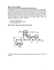
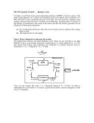
Question 2 (15 marks)A <strong>10</strong>0 MW steam power plant operates as an ideal reheat Rankine cycle as shownbelow. Steam enters the high pressure turbine at 800 ◦ C and <strong>10</strong> MPa. The steam entersthe reheater at 700 ◦ C and 4 MPa and is reheated at constant pressure to 800 ◦ C. Thesteam expands through the low pressure turbine and enters the condenser as a saturatedvapour at 0.01 MPa. Assume the high temperature TER to have a constant temperatureof 1200 K and the dead state to have a constant temperature of T 0 =20 ◦ C. The turbinesand the pump are adiabatic. The pump is isentropic.a) Determine the first and second law efficienciesb) Determine the mass flow rate (kg/s) of the steamc) Determine the mass flow rate of the cooling water in (kg/s), if cooling waterenters the condenser at 15 ◦ C and exits at 35 ◦ CSteamGeneratorqHigh PressureTurbineRHLow PressureTurbinewTTER@1200 KqHCondensercoolingwaterwPPump
State T ( ◦ C) P (MPa) v (m 3 /kg) h (kJ/kg) Comments1 0.01 0.00<strong>10</strong>1 191.83 saturated water2 <strong>10</strong> 201.923 800 <strong>10</strong> 4114.84 700 4 3905.95 800 4 4141.56 0.01 2584.7 saturated vapourPumpFor an isentropic pumpThereforew p = h 2 − h 1 ≈ v 1 (P 2 − P 1 )= 0.00<strong>10</strong>1 m 3 /kg · (<strong>10</strong> − 0.01) MPa · <strong>10</strong> 3 kJ/m3MPa=<strong>10</strong>.09 kJ/kgh 2 =191.83 + <strong>10</strong>.09 =201.92 kJ/kgHigh Pressure Turbinew t1 = h 3 − h 4 =4114.8 − 3905.9 =208.9 kJ/kgReheatq RH = h 5 − h 4 =4141.5 − 3905.9 =235.6 kJ/kgLow Pressure Turbinew t2 = h 5 − h 6 =4141.5 − 2584.7 =1556.8 kJ/kgBoilerq H = h 3 − h 2 =4114.8 − 201.92 =3912.9 kJ/kgPart a)The first law efficiency is given by
η 1st = w t1 + w t2 − w p 208.9 + 1556.8 − <strong>10</strong>.09= =0.423 ⇐q H + q RH 3912.9 + 235.6The availability at the boiler is[ψ b = q H 1 − T ][0=3912.9 · 1 − 293 ]=2957.5 kJ/kgT b 1200The availability at the reheater is[ψ r = q RH 1 − T ][0=235.6 · 1 − 293 ]=178.07 kJ/kgT r 1200The second law efficiency isη 2nd = w t1 + w t2 − w pψ b + ψ r=208.9 + 1556.8 − <strong>10</strong>.092957.5 + 178.07=0.560 ⇐Part b)w net = w t1 + w t2 − w p =208.9 + 1556.8 − <strong>10</strong>.09 =1755.61 kJ/kgṁ =Ẇnetw net=<strong>10</strong>0 MW · <strong>10</strong> 3 kJ/sMW1755.61 kJ/kg=56.96 kg/s ⇐Part c)Taking a control volume around the condenser, the mass and energy rate balances atsteady state giveṁ cw (h cw,out − h cw,in )=ṁ(h 6 − h 7 )Since the cooling water can be thought of as a sub-cooled liquid, the enthalpy can beobtained from the saturated water tables@15 ◦ C → h cw,in ≈ 62.99 kJ/kg@35 ◦ C → h cw,out ≈ 146.68 kJ/kgRearranging, the mass flow rate of the cooling water can be determined as followsṁ cw =ṁ(h 6 − h 7 )h cw,out − h cw,in=56.96 kg/s · (2584.7 − 191.83) kJ/kg(146.68 − 62.99) kJ/kg=1628.60 kg/s ⇐
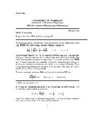
Question 3 (15 marks)The figure below shows the schematic diagram of a vapour-compression refrigerationsystem with two evaporators using R − 134a as the working fluid. This arrangement isused to achieve refrigeration at two different temperatures with a single compressor and asingle condenser. The low temperature evaporator operates at 0.14 MPa with saturatedvapour at its exit, and has a refrigerating capacity of <strong>10</strong> kW . The higher temperatureevaporator produces saturated vapour at 0 ◦ C at its exit and has a refrigerating capacityof 7 kW . Compression is isentropic to the condenser pressure of 1 MPa. There are nosignificant pressure drops in the flows through the condenser and the two evaporators, andthe refrigerant leaves the condenser as saturated liquid at 1 MPa. Calculate the following:a) the mass flow rates [kg/hr] of refrigerant through each evaporatorsb) the compressor power input [kW ]c) the rate of heat transfer from the refrigerant passing through the condenser [kW ]P = 1.0 MPa3 2CondenserP = 1.0 MPaExpansionValveEvaporator2CompressorExpansionValveWcP = 0.14 MPa5ExpansionValveQin,2Evaporator1Q=7kWin,1= <strong>10</strong> kWP = 0.14 MPa6We can make the following assumptions:• steady state, steady flow• ∆KE and ∆PE are negligible• the expansion valves are adiabatic and therefore constant enthalpy devices• the compressor is isentropic• the condenser and evaporators are constant pressure devices
Assembling a table of known and calculated property values:State T ( ◦ C) P (MPa) h (kJ/kg) Comments1 0.14 240.432 1.0 282.263 39.39 1.0 <strong>10</strong>5.29 saturated liquid4 0.29282 <strong>10</strong>5.295 0.14 <strong>10</strong>5.296 0.14 236.04 saturated vapour7 0 0.29282 247.23 saturated vapour8 0.14 247.23 h 7 = h 8Since state points 1, 8 and 6 share a common node they will all have the same pressure.The condenser and the evaporators are constant pressure devices, therefore P 3 = P 2 , P 4 =P 7 and P 5 = P 6 .Part a)higher temperature evaporatorPerforming and energy balance over evaporator 2ṁ e2 · h 4 + ˙Q in,2 = ṁ e2 · h 7˙Q in,2ṁ e2 =h 7 − h 4=7 kJ/s(247.23 − <strong>10</strong>5.29) kJ/kg= 0.0493 kg/s =177.54 kg/hr ⇐low temperature evaporatorPerforming and energy balance over evaporator 1ṁ e1 · h 5 + ˙Q in,1 = ṁ e1 · h 6˙Q in,1ṁ e1 =h 6 − h 5=<strong>10</strong> kJ/s(236.04 − <strong>10</strong>5.29) kJ/kg= 0.0765 kg/s =275.33 kg/hr ⇐
Part b)We can determine the enthalpy at state point 1 by performing an energy balance overthe T-connection formed by state points 6-8-1. Wealso know from a mass balance overthis connectionṁ 1 = ṁ e1 + ṁ e2ṁ 1 · h 1 = ṁ e1 · h 6 + ṁ e2 · h 8(ṁ e1 + ṁ e2 ) · h 1 = ṁ e1 · h 6 + ṁ e2 · h 8h 1 = ṁe1 · h 6 + ṁ e2 · h 8ṁ e1 + ṁ e2(275.33 × 236.04) kJ/s + (177.54 × 247.23) kJ/s=(275.33 + 177.54) kg/s=240.43 kJ/kgKnow that s 1 = s 2 we can obtain the value of h 2 as follows:• from the R134 − a superheated tables at P 1 =0.14 MPa interpolate to find thes 1 knowing h 1 =240.43. This leads to a value of s 1 =0.9491 kJ/kg · K• for an isentropic compressor, s 1 = s 2 =0.9491 kJ/kg · K• from the R134 − a superheated tables at P 2 =1.0 MPa interpolate to find h 2 ata value of s 2 =0.9491 kJ/kg · K. This leads to a value of h 2 =282.26 kJ/kg.The compressor power input can be obtained by performing an energy balance over thecompressorẆ c =(ṁ e1 + ṁ e2 ) · (h 2 − h 1 )=(0.0765 + 0.0493) kg/s × (282.26 − 240.43) kJ/kg= 5.26 kJ/s =5.26 kW ⇐Part c)Performing an energy balance over the condenser, we get˙Q cond =(ṁ e1 + ṁ e2 ) · (h 2 − h 3 )=(0.0765 + 0.0493) kg/s × (282.26 − <strong>10</strong>5.29) kJ/kg=22.26 kJ/s =22.26 kW ⇐
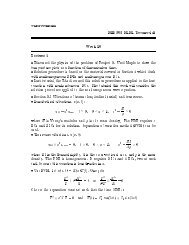
Question 4 (15 marks)Water at 40 ◦ C, 3.5 MPa enters an interfractulator at 0.5 kg/s. Steam at 400 ◦ C,3 MPa also enters the interfractulator at 2.5 kg/s. The interfractulator is a steadilyoperating, adiabatic device. The flow leaves the interfractulator as saturated vapour at350 ◦ C. Assume a dead state temperature of T 0 =20 ◦ C.a) Determine the rate of work transfer [kW ] that can be produced by theinterfractulator operating adiabatically between these three states with the givenmass flow ratesb) Determine the rate of availability destruction [kW ] for this processc) Comment on the feasibility of this processwaterInterfractulatorsaturatedvapoursteamPart a)A mass balance over the interfractulator givesAn energy balance givesṁ 1 + ṁ 2 = ṁ 3ṁ 1 · h 1 + ṁ 2 · h 2 + Ẇ = ṁ 3 · h 3From the saturated water and steam tables, we knowsaturated water @40 ◦ C ⇒ h 1 =167.57 kJ/kg, s 1 =0.5725 kJ/kg · Ksteam @ 400 ◦ C and 3 MPa ⇒ h 2 =3230.9 kJ/kg, s 2 =6.9212 kJ/kg · Ksaturated liquid @ 350 ◦ C ⇒ h 3 =2563.9 kJ/kg, s 3 =5.2112 kJ/kg · KẆ = ṁ 3 · h 3 − (ṁ 1 · h 1 + ṁ 2 · h 2 )= ṁ 1 (h 3 − h 1 )+ṁ 2 (h 3 − h 2 )=(0.5 kg/s) · [(2563.9 − 167.57)kJ/kg] +(2.5 kg/s)[(2563.9 − 3230.9)kJ/kg]= −469.3 kW ⇐
Part b)The availability destroyed is given asẊ des = T 0 [ṁ 1 (s 3 − s 1 )+ṁ 2 (s 3 − s 2 )]=293 K [(0.5 kg/s) · (5.2112 − 0.5725) kJ/kg · K+2.5 kg/s(5.2112 − 6.9212) kJ/kg · K]= −573.0 kJ/s ⇐Part c)The process is impossible since the availability destruction is negative.i.e. Since Ẋ des = T 0 Ṗ s , this implies that the production of entropy is negative. As weknow, the production of entropy in a closed system must be greater than or equal to zero –but never negative.