RD20017 - Kar Kaddy 3 Operators Manual - Demco Products
RD20017 - Kar Kaddy 3 Operators Manual - Demco Products
RD20017 - Kar Kaddy 3 Operators Manual - Demco Products

You also want an ePaper? Increase the reach of your titles
YUMPU automatically turns print PDFs into web optimized ePapers that Google loves.
Page 18-14<strong>RD20017</strong>, Rev 4
Page 2
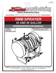
TOW DOLLY USER GUIDEWARNING: Read the following information completely before hooking up, loading, usingunloading or unhooking this Tow Dolly.FAILURE TO FOLLOW THESE SAFETY INSTRUCTIONSMAY LEAD TO DAMAGE TO PROPERTY, SEVERE PERSONAL INJURY, AND/OR DEATH.• Read towing instructions in towed vehicle’s owner’s manual.• Read towing instructions in towing vehicle’s owner’s manual. Be certain that your towing vehicle has the capacityto tow a tow dolly and towed vehicle combination. IF YOU HAVE ANY QUESTIONS ABOUT THIS, DO NOT TOW.CONSULT YOUR DEALER OR CALL DEMCO.• Use a 2”, 6000 lb. (or greater) capacity ball for a tow dolly.• Make sure towing vehicle’s parking brake is fully engaged before starting hookup, loading, unloading, or unhooking oftow dolly.• Do not load towed vehicle onto tow dolly until tow dolly is completely and properly hooked up to towing vehicle andsetting on a level surface.• Tail lights and stop lights must be hooked up and operating properly at all times.• Do not load a towed vehicle that exceeds weight or size limits of tow dolly.• Always have someone safely guide you when driving towed vehicle onto tow dolly.• Be sure tires of your towed vehicle and tow dolly are in good condition and inflated to proper pressures. Tire pressuremay increase during travel—do not bleed off extra pressure.• Do not back up your towing vehicle when a tow dolly is attached. A tow dolly swivels both at the coupler and at carplatform. If you must back up, unload towed vehicle first, disconnect tow dolly and move vehicle and tow dolly separately.Park where you can pull ahead when leaving.• Do not exceed 55 miles per hour, or any lower posted speed limit.• Avoid sharp turns or swerves.• Braking distance increases when using a tow dolly. Use caution and always allow sufficientdistance for braking.• Do not transport passengers or cargo in vehicle being towed.• Do not unhook tow dolly from towing vehicle until towed vehicle is completely unloaded from tow dolly.• Allow one tow-vehicle/tow dolly/vehicle-in-tow length for each 10 m.p.h. behind another vehicle.• ALWAYS check the hitch, tow dolly and vehicle-in-tow at each stop to insure that coupling, chains and tie down equipmentremain tight and properly attached. Use tow dolly checklist as an aid.• NEVER tow without properly installed tire straps and security chains properly attached to frame or other structural memberof vehicle-in-tow.• ALWAYS slow down—40 miles per hour or less—for curves, wet or rough roads, and downgrades. On downgrades,shift into a lower gear and allow engine to help hold speed down.• ALWAYS be rested. NEVER drive when fatigued.• AVOID driving at night. Night drivers have three times the fatality rate of day drivers.• NEVER continue to operate an unstable (swaying or whipping) combination. If this occurs, slowly pull over, reducingspeed through your engine rather than braking. When stopped in an off the road location check hitch, tire straps, andchains.• NEVER pass on hills or curves. Beware of cross winds and wind gusts from passing vehicles.• NEVER transport passengers or cargo in towed vehicle.• ALWAYS load vehicle-in-tow facing forward. NEVER back onto tow dolly. For maximum stability steering axle must beon tow dolly.Page 5
• ALWAYS disconnect drive shaft of a rear wheel drive/front engine vehicle-in-tow at differential to avoid transmissiondamage. Secure disconnected parts.• ALWAYS ensure vehicle-in-tow parking brake is disengaged before towing.• ALWAYS keep children, pets, and bystanders clear of area while loading and unloading.THE MOST IMPORTANT PART - IS YOUWill you read and follow these instructions on how to safely operate this DEMCO Tow Dolly?If your answer is YES, we thank you for your attitude and believe your towing experience will be a safe and pleasantone.SAFETY CHECKLISTWhile Stopped Check• That Hitch is Tight• That Hitch Ball is Tight• Coupler Lever Lock• Are Tire Tie Down Straps Tight• Are Hitch Safety Chains and Vehicle-in-Tow Frame Security Chains Properly Attached• Are Tire Pressures OK• Vehicle-in-Tow for Working Lights• Are Drive Shaft and Battery Cable Disconnected and Secured If Required When On the Road:• Reduce Speed• Think Ahead• Allow for extra length when turning• Anticipate Stops/Brake Early• Stop Often for Rest• Use Safety Checklist at Each StopTOWING VEHICLE SIZE AND TOWING CAPACITYTowing vehicle must weigh at least 750 lbs. more than weight of vehicle-in-tow. Example: A 2,750 lb. car may tow nomore than a 2,000 lb. car.SuspensionYour tow vehicle’s rear springs must be of sufficient strength to support the added loaded tow dolly tongue weightwhile maintaining tow vehicle in approximately a level position. If rear springs, shock absorbers, or struts, are weakor broken, they must be replaced. In some cases, it may be necessary to add helper springs or air shocks to helpsupport weight properly. Poor wheel alignment, loose steering or worn suspension components can also adverselyaffect vehicle handling and stability.Sport Utility VehiclesExercise caution when towing with a sports utility (e.g., Jeep or Bronco) type vehicle. Some of these vehicles have ahigher than normal center of gravity, and a short wheelbase. This gives them different handling characteristics thanthe average car or truck.TiresTow dolly tires should be load range C tires inflated to 50 psi. These are COLD pressures, and will increase when tiresare hot from running. DO NOT bleed off this pressure increase. Incorrect tire pressure can adversely affect vehiclehandling and gas mileage.MirrorsState laws require vehicles towing a tow dolly to be equipped with mirrors on both sides. Inadequate side mirrors createa hazard by limiting rearward vision. If your vehicle is not already so equipped, you should put right and left hand fullview, detachable mirrors on. Ask dealer if it has any available for rent if you do not want to purchase them.Page 6
Never transport any passengers or cargo in towed vehicle. In addition to being illegal in most states, carrying passengersin a towed vehicle exposes those passengers to risk of exhaust gas asphyxiation.Lighting RequirementsEven though tow dollies have operating lights, law requires that a vehicle-in-tow be equipped with functioning stop,turn and running lights. Detachable vehicle-in-tow towing lights can be purchased at many rental locations. They canalso be purchased at auto supply shops. Follow instructions carefully when installing.TOW DOLLY HOOK UPALWAYS FOLLOW HOOK-UP, LOADING, AND UNLOADING INSTRUCTIONS ON FENDER DECALS OF TOWDOLLY. IF YOUR TOW DOLLY DOES NOT HAVE INSTRUCTIONS OR IF THEY ARE ILLEGIBLE, ASK COMPANYFOR A LEGIBLE COPY.TOWING55 Miles Per Hour Max.All vehicle combinations have a speed beyond which adequate emergency control cannot be assured. Maximumrecommended speed for all tow dolly combinations is 55 m.p.h. under good road conditions. As road conditionsdeteriorate you must reduce the maximum recommended speed.Posted speed limit is usually the same for trucks and car-trailer combinations. Observe this limit even if it is less than55 m.p.h.Please do not be lulled into a false sense of security because your tow dolly tows easily at higher speeds. A roadhazard that would be avoidable at 55 m.p.h. can become unavoidable at 65 m.p.h.If you drop any wheel(s) off the pavement, don’t attempt any sharp steering corrections.Remain off the pavement, decrease your speed until you have regained control, then drive slowly back ontopavement.Never Operate An Unstable CombinationInstability (swaying or whipping) of a tow vehicle/ tow dolly combination at low speeds usually increases at higher speeds.If combination begins to whip or sway, steer straight ahead, take your foot OFF the throttle, but do not brake untilcombination has stabilized. Stop in an off the road location and check tow vehicle and tow dolly as soon as possible.• Review all instructions and be sure you have complied.• Check that vehicle on tow dolly is loaded with front wheels on tow dolly. Reload if necessary.• Check that all chains and tie down equipment remain tight and properly attached.• Check for proper tire inflation all around combination.• Make sure trunk or bed of towing and towed vehicles are not loaded with cargo.• Check wheel bearings and lug nuts on both tow vehicle and tow dolly to be sure a wheel has not become loose.• Check tow vehicle’s wheel alignment.• Finally, be sure you are not exceeding maximum recommended speed (55 MPH).•Check coupler and attachment to tow vehicle.If you have followed preceding instructions, any instability should be corrected. If situation persists, stop and call forprofessional assistance from a tow truck operator.Page 8
BREAKDOWNSGet Off The RoadImmediately park tow vehicle-tow dolly combination in a safe place completely off the highway. Get all occupants outof vehicle and away from roadway.If you must continue on the highway to reach a safe place off the road, turn on emergency flashers and proceed withcaution.Do not hesitate to proceed on a flat tire if necessary to reach a safe place completely off the highway. Proceed slowly,for road friction could ignite a flat tire and cause a fire.Rough RoadsTo prevent damage to tow vehicle or tow dolly, reduce speed when towing tow dolly over rough roads.TurningAvoid U-turns. Avoid turning too sharply. Turning too sharply may cause side of vehicle-in-tow to come in contact withrear of dolly fender and cause damage to both vehicles.“Pro” Driving TipsAccidents occur more frequently at night with a tired driver exceeding recommended speed on a downgrade, wet road,or curve. Don’t attempt to drive “straight through.” Be rested. Slow down for down-grades, wet roads or curves. Nightdrivers have three times the fatality rate of day drivers. Avoid driving at night.ACCIDENTSMove all vehicles completely off the road.Get everyone out of the vehicle and off the road. Call police.<strong>Demco</strong> wants youto have a safe towing experience.Read these instructions carefully,read fender decals on tow dolly,and follow all instructions.Page 9
ADecal LocationsGFHCBEEEBDWARNINGRead following information before hooking up,loading, using, unloading or unhooking <strong>Kar</strong><strong>Kaddy</strong> to prevent property damage, seriousinjury , or death.IMPORTANT DO’S & DON’TSRead towing instructions in towed vehicl eowners manual .Use 2” 5000 lb. (or greater) capacity ball for <strong>Kar</strong><strong>Kaddy</strong> without surge brakes and 2” 6000 lb. (orgreater) capacity ball for <strong>Kar</strong> <strong>Kaddy</strong> with surg ebrakes.Assure towing vehicle parking brake is fullyengaged before starting hookup, loading,unloading or unhooking <strong>Kar</strong> Kadd y.Don’t load towed vehicle onto <strong>Kar</strong> <strong>Kaddy</strong> until <strong>Kar</strong><strong>Kaddy</strong> is completely and properly hooked up totowing vehicle and setting on level surface.Always drive front wheels of towed vehicle ont o<strong>Kar</strong> <strong>Kaddy</strong> . Don’t load backwards.Loading T owed Vehicle E1. Assure towing vehicle and <strong>Kar</strong> <strong>Kaddy</strong> arestraight, on level ground, and properlyhooked up before loading towed vehicle.C#2AB2. Remove winch lock pins (A) from strap wincheson front of <strong>Kar</strong> <strong>Kaddy</strong> . RELEASE WINCH: Grasphandle (B) squeeze trigger (C) push down andpull all excess strap from winch. Lay tire strapto outside of <strong>Kar</strong> <strong>Kaddy</strong> .3. Remove STEERING LOCK PIN before loadingvehicle onto <strong>Kar</strong> <strong>Kaddy</strong> to allow AUTO STEERto operate. WHEN KAR KADDY IS EMPTY, THISPIN MUST BE REINSERTED#4Don’t unhook <strong>Kar</strong> <strong>Kaddy</strong> from towing vehicl euntil towed vehicle is completely unloadedfrom <strong>Kar</strong> <strong>Kaddy</strong> .IMPORTANT INFORMATIONCustomer ResponsibilitiesCustomer assumes all risks inherent inoperation, use, or possession of <strong>Kar</strong> <strong>Kaddy</strong> .To wing a vehicle is owners responsibility and itis the owner who must ensure that weight andsize limits of <strong>Kar</strong> <strong>Kaddy</strong> will not be exceeded byvehicle being towed. Any injury or damage thatresults from improper use or exceeding weightor size limits is sole responsibility of owner .Towing V ehicle Requirement sOwner assumes all responsibility for towingvehicle’ s fitness and suitability to performtowing task in safe, legal, and reliable manne r.These responsibilities may include, but are notlimited to:Towing vehicle weight being substantiallygreater (at least 1000 lbs.) than weight of<strong>Kar</strong> <strong>Kaddy</strong> and towed vehicle combined.Compliance with towing restrictions as statedby towing vehicle owner ’s m anual ormanufacturer .To wing vehicle having minimum of 5000 lb.hitch and hitch ball for <strong>Kar</strong> <strong>Kaddy</strong> without surgebrakes, or 6000 lb. hitch and hitch ball for <strong>Kar</strong><strong>Kaddy</strong> with surge brakes. Hitch ball must be 2” .Do not use any other size hitch ball.Towing vehicle’ s hitch being approximately 18inches to top of hitch ball. Make sure that hitchand hitch ball are in good condition and notrusted, loose or stripped. Both hitch and hitc hball must be securely attached to towingvehicle.Towing vehicle must be in good condition.Towing vehicle having a current federal or stat einspection where applicable, and complyingwith any applicable laws.Assure all lights are properly hooked up andoperating at all times.Load W eight and Size LimitsLoad weight is total weight of towed vehicle.Overloading <strong>Kar</strong> <strong>Kaddy</strong> may cause serious injuryor damage to both towed vehicle and <strong>Kar</strong> <strong>Kaddy</strong> .Maximum T owed Vehicle W eight.KK260 KK260SB KK360 KK360SB4400 lbs. 4700 lbs. 4400lbs. 4700lbs.Size limit is overall width. Towed vehicl eexceeding size limit will obstruct platform ’sturning action when towing and could damagetowed vehicle’ s tires and fenders.KK260: 70” max.42” min.KK360 76” max.42” min.INSTRUCTIONS<strong>Kar</strong> <strong>Kaddy</strong> Hook-Up1. Assure towing vehicle parking brake isfully engaged.2. Loosen coupler lock, place coupler of <strong>Kar</strong><strong>Kaddy</strong> over 2” hitch ball on towing vehicle.Assure coupler is fully seated on ball thencompletely tighten coupler lock. Pull up on <strong>Kar</strong><strong>Kaddy</strong> tongue to assure it is properly secured.NOTE: Assure that hitch and hitch ball are ingood condition and not rusted, loose orstripped. Both hitch and hitch ball mustbe securely attached to towing vehicle.3. Connect <strong>Kar</strong> <strong>Kaddy</strong> wire harness to connectoron towing vehicle and check lights for properoperation.4. Criss cross safety chainsunder tongue and attachto mounting loops ontowing vehicle. If <strong>Kar</strong> <strong>Kaddy</strong>is equipped with brakesattach emergency brakecable to one of these loops .Allow some slack in chainsand cable for movement during turning.Failure to follow these instructions couldresult in serious injury or death.REV 1Tail lights and stop lights must be hooked up andoperating properly at all times.Don’t load towed vehicle that exceeds weight orsize limits onto <strong>Kar</strong> <strong>Kaddy</strong> .Always have someone safely guide youwhen driving towed vehicle onto <strong>Kar</strong> Kadd y.Assure tires of towed vehicle and <strong>Kar</strong> <strong>Kaddy</strong> are ingood condition and properly inflated. Tire pressur emay increase during travel, Do not bleed off thisincrease in pressure.Don’t back towing vehicle with <strong>Kar</strong> <strong>Kaddy</strong>attached. <strong>Kar</strong> <strong>Kaddy</strong> swivels both at coupler and atcar platform. If you must back up, unload towedvehicle first, disconnect <strong>Kar</strong> <strong>Kaddy</strong> and movevehicle and <strong>Kar</strong> <strong>Kaddy</strong> separatel y. Play it safe...park where you can pull ahead when leaving.Braking distance increases when using <strong>Kar</strong> <strong>Kaddy</strong> .Use caution and always allow sufficient brakingdistance.Avoid sharp turns or swerves.Descend hills in lower gear. Avoid sudden brakingor lane changes when descending a hill.Don’t transport passengers or cargo in vehicl ebeing towed.RD21002#34. Loosen wing nut on back of license plate holder ,turn clip on front to horizontal position andput license in “down” position. Turn clip backso it rests against back of light to hold license“down” and tighten wing nut. (License must be“up” with <strong>Kar</strong> <strong>Kaddy</strong> empty).#55. Grasp bed release handle on tongue andpull toward coupler . This releases tilt bed.6. Before loading (and unloading) towed vehicl emake sure platform and towed vehicle are instraight alignment . Don’t load towed vehicleonto KAR KADDY until completely and properl yhooked up to towing vehicle and setting onlevel surface.7. With someone safely guiding you, centervehicle to <strong>Kar</strong> <strong>Kaddy</strong> . Slowly drive vehicl eforward, until tires touch wheel stops at frontof platform. DO NOT BACK VEHICLE ONTOKAR KADDY. Assure that towed vehicle iscentered on <strong>Kar</strong> <strong>Kaddy</strong> platform and tires fit inwheel pans without hanging over sides.8. Place towed vehicle in park (low gear if it hasstandard transmission), engage parking brake,shut off engine, remove ignition key, locksteering wheel of towed vehicle with tires in astraight forward position. If towed vehicle doesnot have a locking steering column, steerin gwheel must be securely tied.#99. Place tire straps over tires centering straps andwinches to tires, avoiding contact withsuspension components. Short side of hookmust face rear of <strong>Kar</strong> <strong>Kaddy</strong> . While tighteningstraps, pull cross straps forward to ensure eventightening. Tighten straps until each tire start sto flatten against tire stop. After strap is tightand with ratchet handle in down (horizontal )position insert lock pin through hole in ratchetpawl arm and ratchet frame then attach retainerclip. Hook safety chains to frame of towedvehicle directly above area where chains aremounted on <strong>Kar</strong> <strong>Kaddy</strong> .IMPORTANT: Chains must not attach to or goover steering or brake parts. Leave enoughslack in chains for suspension movement.Check tire straps after first 5 miles of travel andevery 50 miles thereafter to ensure they aretight and not rubbing or fraying on suspensio ncomponents of towed vehicle.10. If towed vehicle is rear wheel or four wheeldrive, disconnect drive shaft. (Simply placingtransmission in neutral is not sufficient toprevent damage to transmission). You mustdisconnect drive shaft at rear axle and removeit. With the drive shaft removed it will benecessary to cap the transmission tail shaft toprevent transmission fluid loss.Rear engine/transaxle vehicle cannot be towedwith <strong>Kar</strong> <strong>Kaddy</strong> . (All vehicles loaded on <strong>Kar</strong><strong>Kaddy</strong> must be loaded with front of vehicl efacing forward). Consult your vehicle owner ’smanual to help determine if and how yourvehicle is suitable to be towed.11 . RELEASE PARKING BRAKE ON TOWED VEHICLE.Ensure that steering wheel is locked in straightforward position, remove ignition keys andlock doors of towed vehicle.12. Release parking brake on towing vehicle anddrive forward 100 feet. Stop and perform safetycheck. Check hitch, hitch ball, ball coupler ,safety chains, tire straps, bolts and other item sto ensure they are tight and in correct position.Check all lights to make sure they are operatin gproperly . Repeat safety check after first 5 mile sand every 50 miles thereafter .NOTE: Do not unhook <strong>Kar</strong> <strong>Kaddy</strong> from towingvehicle until towed vehicle is completelyunloaded from <strong>Kar</strong> <strong>Kaddy</strong> .Unloading To wed Vehicle1. Assure towing vehicle and <strong>Kar</strong> <strong>Kaddy</strong> arestraight, on level ground, and properly hookedup before unloading towed vehicle.2. Fully engage parking brake of towing andtowed vehicles.3. If removed, reinstall drive shaft of towedvehicle.4. Straps may be “quick released” by removinglocking pin, grasping ratchet pawl and ratchethandle simultaneously and pushing downsharpl y. This process will permit easy remova lof strap from winch.5. Remove tire straps and safety chains fromtowed vehicle. Also release tilt bed as shown inillustration #5.6. Release parking brake of towed vehicle andslowly back towed vehicle off <strong>Kar</strong> <strong>Kaddy</strong> .7. On level ground check the transmission fluidlevel of towed vehicle. Fluid may have leakedout during towing.8. Store safety chains and straps intheir storage position on each side.9. Return tilt bed to locked position and reinser tsteering lock pin. As shown in illustration #3A. RD21002 Qty. 1B. RD21008 Qty. 2 C. BC21014 Qty. 1D. DD21016 Qty. 1E. DD21022 Qty. 4BRAKES ON BRAKES OFFDO NOT TOW TOWABLEBH21003H. BH21003 Qty. 1Page 10CAUTIONActuator is springloaded. Use care whenservicing or injury mayoccur.REV 1NP21010F. NP21010 Qty. 1ATTENTIONThis brake actuator isspecially designed foruse with disc brakesONLY.Any replacement ofthis unit MUST be ofthe same design.REV 1ordered 01-22-01 with no changesordered 04-02-01 with no changesordered 10-02-02 with no changesordered 05-20-04 with no changesordered 09-20-04 with no changesthis file was ordered 03-03-05this file was ordered 05-24-05this file was ordered 08-09-05this file was ordered 09-06-05this decal was ordered 11-09-05decal was ordered 11- 28-05BD21001G. BD21001 Qty. 1
BOLT TORQUETORQUE DATA FOR STANDARD NUTS, BOLTS, AND CAPSCREWS.Tighten all bolts to torques specified in chart unless otherwise noted. Check tightness of boltsperiodically, using bolt chart as guide. Replace hardware with same grade bolt.NOTE: Unless otherwise specified, high-strength Grade 5 hex bolts are used throughout assemblyof equipment.Bolt Torque for Standard bolts *Torque SpecificationsTorque wheel nuts to 120 ft/lbsGRADE 2 GRADE 5 GRADE 8“A” lb-ft (N.m) lb-ft (N.m) lb-ft (N.m)1/4” 6 (8) 9 (12) 12 (16)5/16” 10 (13) 18 (25) 25 (35)3/8” 20 (27) 30 (40) 45 (60)7/16” 30 (40) 50 (70) 80 (110)1/2” 45 (60) 75 (100) 115 (155)9/16” 70 (95) 115 (155) 165 (220)5/8” 95 (130) 150 (200) 225 (300)3/4” 165 (225) 290 (390) 400 (540)7/8” 170 (230) 420 (570) 650 (880)1” 225 (300) 630 (850) 970 (1310)Bolt Torque for Metric bolts *Torque figures indicated are valid fornon-greased or non-oiled threads andheads unless otherwise specified.Therefore, do not grease or oil bolts orcapscrews unless otherwise specifiedin this manual. When using lockingelements, increase torque valuesby 5%.* GRADE or CLASS value for boltsand capscrews are identified by theirhead markings.CLASS 8.8 CLASS 9.8 CLASS 10.9“A” lb-ft (N.m) lb-ft (N.m) lb-ft (N.m)6 9 (13) 10 (14) 13 (17)7 15 (21) 18 (24) 21 (29)8 23 (31) 25 (34) 31 (42)10 45 (61) 50 (68) 61 (83)12 78 (106) 88 (118) 106 (144)14 125 (169) 140 (189) 170 (230)16 194 (263) 216 (293) 263 (357)18 268 (363) -- -- 364 (493)20 378 (513) -- -- 515 (689)22 516 (699) -- -- 702 (952)24 654 (886) -- -- 890 (1206)Torque 11MM caliper bolts to 40 ft/lbsGRADE-2 GRADE-5 GRADE-8 CLASS 8.8 CLASS 9.8 CLASS 10.9A8.8 9.8 10.9Page 11
Tongue and Ramp Assembly Instructions1. Place the main frame (#1) on blocks or some other sturdysupport so that the frame rests approximately 8” - 10” offthe ground.2. With an assistant, place tongue assembly (#2) into mainframe channel and position latch on tongue approximately3” from front of channel. Clamp tongue to main frame andsupport front of tongue.3. Locate the four bullet connectors extending out the backof the tongue and plug into the connector protruding fromunder the main frame channel. Plug into the flat four connectorby matching the colors. Do not cross colors whenmaking this connection. Make sure that the two pigtailsfor the license plate bracket are out.4. With an assistant, mount the tongue assembly (#2) tothe front of the <strong>Kar</strong> <strong>Kaddy</strong> main frame and use a 5/8” x4-1/2” grade 5 bolt (#3) and lock nut (#4)(torque to 50 ft.lbs). Do not torque over 50 ft. lbs. or bed will not tilt.NOTE: Brake line and wiring must be above bolt alsocoupler assembly must be ahead of bolt. Do this byopening tongue about half way.5. Lay the bracing struts (#5) out along the tow dolly tonguewith the back end (the end with the larger hole in it) ofthe bracing strut toward the main frame. Loosely bolt theback of each bracing strut to the trailer frame as shownusing 1/2” x 1-1/2” grade 5 bolt (#6), flatwasher (#7), pivotbushing (#8) and locknut (#9). Hold up the front end(the end with the smaller hole) of each bracing strut tothe tongue and secure with two 5/8” x 1-1/4” epoxied hexhead bolts (#10) and nut plate (#19). Torque the 1/2” x1-1/2” bolt with the pivot bushing to 75 ft. lbs. Torque thetwo 5/8” x 1-1/4” epoxied hex head bolts to 100 ft. lbs.6. Attach the tilt bed ramps (#11) as shown using four 1/2”x 1-1/4” grade 5 bolts (#12), flat washer (#7) and locknuts (#9), two on each side of each ramp, and then three7/16” x 1” grade 8 bolts (#13) and lock nuts (#14) on thetop of each ramp. Torque 7/16” bolts to 80 ft. lbs. andtorque 1/2” bolts to 75 ft. lbs.7. Attach rear tire stop (#15) as shown using two 3/8” x1-1/4” grade 5 bolts (#16), flat washers (#17) and lock nuts(#118). These 3/8” x 1-1/4” bolts will also go through thetilt bed ramps. Torque 3/8” x 1-1/4” bolts to 35 ft. lbs.8. Repeat steps 6-7 for other side.161513171814111297857694110319267 8105Page 12
Fender Assembly Instructions1. Install fender with fender backup plate (#1) and three 3/8”x 1-1/2” bolts (#2). Put 3/8” nylon lock nuts (#3) inside offender and tighten.3. On the left side, plug in bullet plugs with white towhite, black to brown and yellow to red. On the rightside, plug white to white, black to brown and greento red.2. Cut nylon wire tie from wiring to brake hose on main frame,(used for shipping purposes only). Fish the three wiresfrom main unit through the hole in fender.4. With a pliers, install two wire clamps on fender. From rearof fender lip, install one clamp at 5-1/2” and one at 8”.5. Mount the mud flaps (#4) to the inside back of the fenderusing two 1/4” x 3/4” truss head bolts (#5) with flat washers(#6) and lock nuts (#7). Make sure the <strong>Kar</strong> <strong>Kaddy</strong> logoon the flap faces the rear.51263 47Page 13
Warning: Failure to follow these instructions can result in loss of towing vehicle control, separationof the tow dolly from the towing vehicle, separation of the towed vehicle from the tow dolly,causing severe personal injury, death, or property damage.SAFETYSafety is of utmost importance at all times. There are several itemsthat must be checked each time before using and while using the<strong>Kar</strong> <strong>Kaddy</strong>.Make sure all bolts are properly tightened and those requiring a settorque are up to specifications:Tie Rod Castle Nut - 75 ft./lbs.Lug Nuts - 120 ft./lbs.Check Lug Nut tension after the first 5 miles and periodicallythereafter.The ball hitch must latch securely around the ball and the safety lockpin or lever must be in position to lock the hitch on the ball.RECOMMENDED BALL HEIGHT: 18 inches to the top of the ballon the towing vehicle.Hook the towed vehicle safety chains to the frame of the vehicledirectly above the area where the chain is mounted on the <strong>Kar</strong> <strong>Kaddy</strong>.Leave some slack in the chain to allow suspension movement.Check to make sure that all lights are in proper working order.Examine the winches and straps, making sure they are in goodcondition.Be certain the safety lock pins are locking the strap winches.Retighten straps over the tires after the first 5 miles and every 50miles thereafter. Ensure that they are tight.The tires must be inflated to the recommended 50 PSI.The strap on the optional tongue winch must be in good conditionand should be stored neatly on winch when not in use.NOTE: The winch strap must not be left connected to the towedvehicle after it is loaded and strapped down.Make sure the optional light bar is fastened securely at the rear ofthe towed vehicle.The wires to the optional light bar should be run along the car andfastened so as not to damage the finish of the towed vehicle.NOTE: This unit cannot be backed up, when loaded or with thesteering lock pin removed.All vehicles mounted on the <strong>Kar</strong> <strong>Kaddy</strong> must be mounted with thefront of the vehicle facing forward.Rear Wheel Drive: Disconnect the towed vehicle driveshaft for rearwheel drive vehicles with automatic transmission.For manual transmission: Consult your vehicle owners manual fortowing suitability with the drive shaft connected.MAINTENANCEPeriodically check all bolts and nuts to insure proper tension ortorque.Grease the king pin and tie rod end grease zerks every 2500miles.An occasional drop of oil may be required on the moving parts ofthe tie down winches.A light film of oil should periodically be applied to steering stabilizershaft to prevent rust.NOTE: Proper toe-in is 1/32”. This is preset at the factory.The operator should periodically have the toe-in checked and adjustedif needed at a qualified alignment shop. Improper toe-in canresult in irregular tire wear.IMPORTANT LOADING INSTRUCTIONCheck your wheel tie-down straps.Your <strong>Kar</strong> <strong>Kaddy</strong> is equipped with custom made wheel tie-down strapsof a standard size that will fit most tires, however if your tires aretoo large or too small you will want to exchange these new strapsfor the proper size straps.1. Tire too large - This is very obvious the strap will not basketover the tire properly, call us, we will provide at NO Chargeon an exchange basis, the proper size strap. You must returnyour new unused straps and provide us with the Make andModel car and the tire size.2. Tire too small - This is not as obvious, the basket will fit downover the tire very well, the problems cannot be readily seen.You must tighten the straps down solid and then check on theinside of the tire and be sure the strap, when tightened doesnot come in contact with any metal that may cause wear orcutting such as strut mounts. If there is contact, you needa smaller strap, call us, we will provide on a NO Charge,exchange basis, the proper size strap. You must return yournew unused straps and provide us with the Make and Modelcar and tire size.Thank you for Purchasing<strong>Products</strong>.IMPORTANT:Using this guideline will reduce the chance of the towed vehiclesair dam, or bottom of facia from interfering with tow dollyplatform and or tire stop. “X” must be less than 4.2 x “Y”.Example: If Y measures 5”4.2 x 5 = 21X must measure less than 21”Loading Angle Clearance Guide<strong>Kar</strong>-<strong>Kaddy</strong> 3 Loading Angle = 13.4°NOTE: User’s responsibility for checking clearancePage 14
LOADING INSTRUCTIONSStep 1. Secure ball coupler to 2” (6,000 lb. capacity) towingvehicle ball only. Make sure that the hitch and the hitchball are in good condition and not rusted, loose or stripped.Recommended ball height is 18” to the top of the ball.Make sure hitch is locked down and secured with safety clip.Criss-cross safety chains under tongue and secure to towingvehicle frame.Step 2. Remove black locking pin BEFORE loading vehicleonto the <strong>Kar</strong> <strong>Kaddy</strong>. The removal of the locking pin allows“Auto Steer” to operate. When towing the dolly empty, thispin must be in place.Step 4. Before loading (and unloading) towed vehicle makesure platform and towed vehicle are in straight alignment.Tow dolly must be completely and properly hooked up to thetowing vehicle. Towing vehicle must be larger and at least1000 lbs. heavier than the tow dolly and towed vehiclecombined.Step 3. Loosen wing nut on back of license plate holder, turnthe clip on the front to a horizontal position and put licensein the “down” position. Turn the clip back so it rests againstthe back of the light bar to hold the license down and tightenwing nut.(License must be “UP” with the tow dolly empty).IMPORTANT: Tire tread width or body width of towed vehiclemust not exceed:76” max. (outside to outside),42” min. (inside to inside),76” max. (body width).Page 15Step 5. Grasp bed release handle on tongue and pulltoward coupler. This releases the tilt bed to permit loading.
Step 8. Place one tie-down strap over each tire and securehooks to rods located at the rear of each wheel platform. Theshort side of the hook must face the rear of the <strong>Kar</strong> <strong>Kaddy</strong>.Step 6. With someone safely guiding you, slowlydrive vehicle onto platform FRONT FORWARD. (Any vehiclemounted on tow dolly must be mounted with front of thevehicle facing forward.) Drive the car forward until the tirestouch the ramps. Make sure the tire is aligned to ascendonto the ramps.Step 9. Be sure tie-down winch is centered with the tirebefore tightening straps.Step 7. Drive vehicle onto the platform - front forward - untiltires touch the wheel stops at the front of each side of theplatform and the platform tilts to a flat position. Make sure thecar is centered on the platform. Towed vehicle tires must fitin wheel troughs without overhanging sides. Engage towedvehicle parking brake. Shift loaded car into “park” and locksteering wheel with front tires in a straight position. If the cardoes not have a locking steering column the steering wheelmust be tied securely with front tires in a straight position.Rear Wheel Drive: Disconnect towed vehicle driveshaft forrear wheel drive vehicles with automatic transmission.For manual transmission: Consult your vehicle ownersmanual for towing suitability with the drive shaft connected.Step 10. Thread tie-down strap through the slotted tube onthe tie-down winch. Pull approx. 6” of strap through this slot.Begin tightening strap making sure the tail becomes enclosedby the strap coming over the tire. Tighten the straps ensuringthat the strap fed through the slot binds between the shaft andthe strap being wound onto the winch shaft. While tighteningstraps, pull cross strap forward to ensure even tightening.NOTE: Be sure to tighten straps until each tire starts toflatten against tire stop. After each strap is tight, insert asafety pin in each winch. Disengage towed vehicle parkingbrake.Straps must be retightened after first 5 miles of travel.Check straps every 50 miles thereafter to ensure they aretight and not rubbing or fraying.Page 16
Step 11. Make sure the tie-down strap is the correct sizefor the auto tire. See page 11 of this instruction for proper fitand exchange instructions.Step 14. To pull the <strong>Kar</strong> <strong>Kaddy</strong> empty, make sure “Auto-Steer” LOCKING PIN IS IN PLACE and towing vehiclesafety chains are up and hooked. Tie-down winch handlesshould be left in a down position (horizontal) position withsafety pins in place when towing loaded or empty. DO NOTATTEMPT TO PULL KAR KADDY WITH WHEEL PLATFORMIN LOADING (tilted) POSITION.Step 12. Hook the towed vehicle safety chains to frame ofvehicle directly above the area where the chains are mountedon the <strong>Kar</strong> <strong>Kaddy</strong>. Leave some slack in the chains to allowsuspension movement of the towed vehicle.BDAMAGE PREVENTIONCheck your vehicle manual or registration for vehicle weight.Towing vehicle must be larger and at least 1,000 lbs. heavierthan the towed vehicle and tow dolly combined.Do not pack goods in car that is being towed. Overloadingthe <strong>Kar</strong> <strong>Kaddy</strong> or exceeding the width limit may result indamage to both car and <strong>Kar</strong> <strong>Kaddy</strong>.REAR WHEEL DRIVE PRECAUTIONSDisconnect towed vehicle driveshaft for rear wheel drivevehicles with automatic transmission. Simply placingtransmission in neutral is not sufficient to prevent damageto transmission.For manual transmission: Consult your vehicle owners manualfor towing suitability with the drive shaft connected.ALL VEHICLES MOUNTED ON THE KAR KADDY MUST BEWITH THE FRONT OF THE VEHICLE FACING FORWARD.AStep 13. TO UNLOAD towed vehicle. Make sure that platformand vehicle are straight. Reinstall driveshaft. Ensure thattowed vehicle parking brake is fully engaged, then unhookthe towed vehicle safety chains, and release the tie-downstraps. NOTE: Tie down straps must be “quick -released”by grasping ratchet pawl (A) and ratchet handle (B) simultaneouslyand pushing down sharply. This process will permiteasy removal of strap from winch. Swing the wheel platformlocking latch handle forward, towards the coupler. This willallow the platform to tilt as you slowly drive off. Make surethe winch ratchet handles are horizontal. Replace the “AutoSteer” locking pin (for towing empty).CAUTION• Examine winches and straps to make sure they are ingood condition.• Check wheel nuts every trip.• Tires must be inflated to recommended pressure bytire manufacturer.• Be certain the safety lock pins lock the strap winches.• Retighten the straps over the tires after the first 5 milesof travel. Check straps every 50 miles thereafter toensure they are tight and not rubbing or fraying.Page 17
REF. PARTNO. NO. QTY. DESCRIPTION1. 03528 2 Tie-down Strap assembly, Black2. 5981 1 Right Large Fender Assembly with Lights3. 5980 1 Left Large Fender Assembly with Lights4. 04424-95 2 Fender Backing Plate5. 00914 6 3/8”-16UNC x 1-1/2” Hex Head Bolt (gr.5)6. 02592 18 3/8”-16UNC Nylon Lock Nut7. 12560-81 1 Right Wheel Carrier8. 12559-81 1 Left Wheel Carrier9. 01732 4 1”I.D. x 1-1/4”O.D. x 1-1/2”lg. Bushing (brnz)10. 11588 2 King Pin (1” x 6-1/2”)11. 01731 4 1-1/4” Dust Cap12. 01978 2 1” I.D.x 18 GA Narrow Rim Machine Washer13. 35652-81 1 Right Drop Axle & Wheel Carrier Assembly14. 35651-81 1 Left Drop Axle& wheel Carrier Assembly15. 11551 2 King Pin Retainer Bolt16. 03724 2 7/16”-20UNF Center Punched Nut17. 02377 10 7/16”-20UNF x 1-1/2” Epoxy Bolt (gr.8)18. 04168 8 7/16”-20UNF Nylon Lock Nut19. 02178 17 1/2”-13UNC Nylon Lock Nut20. 02579-95 2 Pivot Bushing21. 00085 15 1/2” Flatwasher22. 01254 15 1/2”-13UNC x 1-1/2” Hex Head Bolt (gr.5)23. 02747-96 2 Bracing Strut24. 03503 2 5/8”-11UNC x 1-1/4” Epoxy Bolt (gr.5)25. 02434 1 5/8”-13UNC x 4-1/2” Hex Head Bolt (gr.5)26. 02587 3 5/8”-13UNC Nylon Lock Nut27. 02696 2 5/8”-11UNC x 2-3/4” lg. Hex Head Bolt (gr.5)28. 14100 1 5/8” Flatwasher29. 01729-30 1 Steering Stabilizer Shock30. 11553-81 1 Tie Rod Clamp, Bottom31. 11554-81 1 Tie Rod Clamp, Top32. 00907 12 3/8”-16UNC x 1” Hex Head Bolt (gr.5)33. 02494 2 3/8”-16UNC x 2-1/4” Hex Head Bolt (gr.5)34. 00967 9 1/2”-13UNC x 1-1/4” Hex Head Bolt (gr.5)35. 04772-96 2 Ramp36. 01718-95 1 Tie Rod Locking Pin- 02189 1 Replacement Black Handle Grip for Locking Pin37. 00182 1 Hair pin38. 11933-81 1 KK370SB Main Frame39. 5740 1 License Plate Bracket Assembly40. 5553-81 1 Tie Rod Assembly w/ ends41. 5179A 1 Right Tie Rod End w\Right Hand Threads & Jam Nut42. 5178A 1 Left Side Tie Rod End w\ Left Hand Threads & Jam Nut43. 01905 1 9/16”-18UNF Jam Nut w/Right Hand Threads44. 01904 1 9/16”-18UNF Jam Nut w/Left Hand Threads45. 04773-96 2 Rear tire Stop46. 00523 4 3/8”-16UNC x 1-1/4” lg. Hex Head Bolt (gr.5)47. 02243 1 Black Vinyl Hand Grip48. 12714-81 1 Tongue49. 6057 1 DA91 Actuator with 2” eZ-Latch Coupler50. 5433 1 Right Winch assembly51. 5432 1 Left Winch Assembly52. 02772 2 1/4”-20UNC Nylon Lock Nut53. 04177 2 1/4”-20UNC x 1” Carriage Bolt54. 13920-92 2 Caliper Mount55. 03927-92 2 10” Brake Rotor56. 01898 4 7/16” x 1 -1/4” Hex Head Bolt (gr.5)58. 00059 8 3/8” Flat Washer59. 02209 2 7/16”-14UNC Nylon Lock Nut60. 02383 2 36” Safety Chain61. 04017-95 1 Bolt on Handle62. 02189 1 Rubber Handle Grip63. 01338 1 1/2”-12UNC x 4-1/2” lg. Hex Head Bolt (gr.5)64. 01975 2 1/2”-12UNC x 5” lg. Hex Head Bolt (gr.5)65. 04174 4 Retainer Washer66. 04369 2 Hub and Spindle- 02917 - Replacement 12mm x 1.50mm Stud Bolt67. 02210 8 7/16”-20UNF x 1-1/4” Epoxy Bolt (gr.8)68. 13989 2 ST205/75R14 “C”Range Radial Tire69. 09296 2 Rim, 14 x 5.5, 5 on 115mm B.C.KK370SB PARTS BREAKDOWNREF. PARTNO. NO. QTY. DESCRIPTION70. 02933 10 Chrome Lug Nut71. 04167 6 7/16”- 20UNF x 1” hex head bolt (gr.8)72. 04168 6 7/16”-20UNF Nylon Lock Nut73. 12445-30 1 Spring Return System74. 12238 2 Safety Cable 36”75. 12229-95 2 Safety Cable Mounting Washer76. 12253 - Safety Hook Spring Clip Replacement77. 11971-95 2 Nut Plate78. 13825-92 2 Brake Caliper Assembly79. 04462 2 Urethane SnubberPlease order replacement parts by PART NO. and DESCRIPTION.Page 18197374195921214975607617506157562164267910115823246263122021
Page 19386614151617181926272130313233343535444266676869704 51319202122222324252626272829363738394041434145464647485152525353545565158671197277787979
WINCH ASSEMBLY512Left Winch 5432 (Shown)Right Winch 54337111834148693121315101617- 5432 - Left Winch Assembly- 5433 - Right Winch Assembly1. 00214 1 1/4”Flat Washer2. 01076 1 1/4”-20 UNC x 3/4” Hex Head Bolt3. 01864 2 Spring4. 02772 2 1/4”-20 UNC Nylon Insert Locknut5. 05337 1 Lock Pin w/ Cable6. 00004 2 5/16” Flat Washer7. 02243 1 Black Vinyl Hand Grip8. 05444 1 3/8”-16 UNC x 3/4” Hex Head Bolt w/ Epoxy9. 05449 1 Winch Pawl Bushing (Stainless Steel)10. 05450 1 Winch Pawl11. 03572-95 1 Left Ratchet Pawl Arm- 03573-95 1 Right Ratchet Pawl Arm12. 03574-95 1 Ratchet Handle13. 03575-95 1 Left Outer Ratchet Gear- 03576-95 1 Right Outer Ratchet Gear14. 03666 1 5/16” x 1-1/4” Roll Pin15. 03668 1 1” x 18 Gauge Machine Washer16. 03578 1 5/16”-18 UNC x 1/2” Socket Head Shoulder Bolt17. 01998 1 5/16” Flat Washer (Stainless Steel)18. 02002 1 1/4” Flat Washer (Stainless Steel)TILT-BED LATCH ASSEMBLY1314891416112181517 11012653 47KIT #5511TILT-BED LATCHASSEMBLYREF. PARTNO. NO. QTY. DESCRIPTION5511 - Tilt-Bed Latch Kit1*. 03434 1 5/16”-18 UNC x 4” Eye Bolt2*. 04221 1 5/16”-18 UNC x 2-1/2 Hex Head Bolt (Gr 5)3*. 00004 1 5/16” Flatwasher4*. 00007 1 5/16”-18 UNC Hex Nut5*. 03379-95 1 Latch Block6*. 03435 1 Roll Pin (5/16” x 2-1/4”)7*. 03499 1 Latch Spring - Stainless Steel8. 03382-95 1 Latch Handle Pivot Bushing9. 03574-95 1 Latch Handle10. 03381-95 1 Latch Catch11. 03433 1 Latch Cable12. 02802 1 5/16-18 UNC Nylon Insert Locknut13. 00967 8 1/2”-13UNC x 1-1/4” lg. Hex Head Bolt (gr.5)14. 00085 1 1/2” Flatwasher15. 00059 9 3/8” Flat Washer16. 02178 13 1/2”-13UNC Nylon Insert Locknut17. 05449 1 Spacer Bushing - Stainless Steel18. 05444 1 3/8”-16 UNC x 3/4” Epoxied Hex Bolt (Gr 5)Please order replacement parts by PART NO. and DESCRIPTION.* Items included in 5511 kitPage 20
LICENSE PLATE BRACKET ASSEMBLY3124423107(not available)86107105740License Plate Mountand Light Cluster596REF. PARTNO. NO. QTY. DESCRIPTION5740 - License Plate Bracket and Light Assembly1. 04505-95 1 License Plate and Light Cluster Bracket2. 04176 2 1/4”-20UNC X 3/4” Carriage Bolt3. 02214 2 #10 NC X 1/2” Slotted Truss Head Screw4. 02163 1 Square License Plate Light w/Washer and Nut- 02164 - Clear License Plate Light Lens Only5. 02580-95 1 License Plate Clip6. 02770 2 1/4”-20UNC Nylon Insert Wing Nut7. 02205 2 #10 NC Nylon Lock Nut8. 00214 1 1/4”-20UNC Flat Washer9. 11687* 1 3 Cluster Light Bar Only (No Lights)10. 11688* 3 Red LED Light- 11655* 1 3 Cluster LED Wiring Harness- 11616 1 Gromment, 5/8” OD x 3/8” x 1/8” Thick- 5765 - 3 Cluster LED Light Assembly (* Included)Please order replacement parts by PART NO. and DESCRIPTION.Fender Assembly6817918111441013152 32221917162125PARTS LISTREF.NO. PART NO. QTY. DESCRIPTION5980 - Left Large Fender Assembly5981 - Right Large Fender Assembly1. 01883 2 Wire Splicer2. 04425 5 Tinnerman U-clamp3. 04515 1 17-1/2” Wire Loom4. 04643 2 9/16” x 5/8” Pop Rivet5. 05443 1 Nylon Cable Hanger6. 05447 1 4” Light Grommet7. 07081 1 Tail Light Wire Harness8. 05446 1 4” Round Tail Light9. 14119 1 Left Fender Assembly- 14120 1 Right Fender Assembly10. 11973 1 Black Marker Base Mount11. 11975 1 Yellow Marker Light12. 11619 1 12” Wire Loom13. 11974 1 Front Marker Wiring Harness14. 04508 1 Amber Reflector- 04804 1 Red Reflector15. 07490 2 3/16” Washer16. 01769 1 <strong>Kar</strong> <strong>Kaddy</strong> Mud Flap17. 02772 2 1/4” Nylon Lock Nut18. 05338 2 1/4” Slotted Truss Head Bolt19. 00214 2 1/4” Flat WasherPlease order replacement parts by PART NO. and DESCRIPTION.Page 21
MODEL DA91 ACTUATOR PARTS BREAKDOWN8138175482 Master Cylinder Repair Kit(gasket included)**102523**16**121514141518263029205876 eZ-LatchCoupler RepairKit224928275672421191922133Model 91 ACTUATOR PARTS LIST2” eZ-Latch Coupler RATEDAT 10000#Bleeding the SystemThe first requirement for safe, sure hydraulic braking is the useof quality brake fluid. Use only DOT-3 or DOT-4 brake fluid froma sealed container.If pressure bleeding equipment is available, follow the manufacturer’sinstruction in bleeding the system.If system must be bled manually, proceed as follows: Fillmaster cylinder with fluid. Install bleeder hose on top bleederof first caliper to be bled.NOTE: always bleed brakes by using the top bleed screwon the caliper.Have loose end of hose submerged in brake fluid in glasscontainer to observe bubbling.By loosening the top bleeder screw located on the caliper oneturn, the system is open to the atmosphere through the passagedrilled in the screw. Pump actuator with long steady strokes.The bleeding operation is completed when bubbles no longerrise to the surface of the fluid. Be sure to close bleeder screwsecurely.Repeat bleeding operation at each caliper. During the bleedingprocess, replenish the brake fluid, so the level does not fallbelow the 1/2 full level in the master cylinder reservoir. Afterbleeding is complete, make sure master cylinder reservoir isfilled and filler cap is securely in place.After the bleeding operation has been completed, apply pressureto the system and check the whole brake system for leaks.Page 22REF.NO. PART NO. QTY. DESCRIPTION1. 12925 1 10000# 2” eZ-Latch Coupler2. 01896 3 1/2”-13UNC x 4” Hex Head Bolt (gr.5)3. 02178 3 1/2”-13UNC Nylon Insert Lock Nut4. 05426 1 Front Shock Pin (drop tube actuators)5. 11079-95 1 Drop Tube Actuator Slider (plated)6. SB12426 1 Damper/ Shock7. 11164-95 1 3 Bolt Mount Outer Case (plated)8. 05424 2 5/16” External Tooth Lock Washer9. 12557 1 Rue Cotter Pin for 5/8” Pin**10. 05408 1 Breakaway Cable Kit**12. 05693-95 1 Emergency Lever Spring (plated)13. 05961 2 5/16”-18UNC x 5/8” Hex Head Bolt (gr.5)14. 00618 4 1/4-20UNC x 2” Hex Head Bolt (gr.5)15. 00057 4 1/4” Lock Washer**16. 05951 1 Emergency Lever Assembly17. 03876 1 Master Cylinder Cap w/ Diaphragm & O-ring- 05849 1 O-Ring Only (not shown)18. 05977 1 Push Rod Assembly19. 00062 4 1/4”-20 UNC Hex Nut** 20. 09153 - Plastic Master Cyl. Gasket ONLY21. 11190 1 Master Cylinder22. 14798 1 90° Brake Fitting** 23. 03866-95 1 Lever Guide (plated)24. 05687 1 Master Cylinder Protective Boot25. 05986-95 1 Connecting Pin (plated)26. 10965 1 Upper Slider27. 10966 1 Lower Slider28. 10967 2 Side Spacers29. 12557 1 Master Cylinder Cap30. 12397 1 Rue Cotter Pin for 7/8” Pin- 8669113 - DA91 Actuator w/ 2” eZ-Latch Coupler- 6057 - DA91 Actuator without Coupler- 5401 - Lever Replacement Kit (incl. items w/**)- 5482 - Master Cyl. Replacement Kit (disc)- 5876 - eZ-Latch Coupler Repair KitPlease order replacement parts by PART NO. and DESCRIPTION
DISC BRAKE PARTS BREAKDOWN AND PARTS LISTHub Assembly510792146Epoxy Bolt38PARTS LISTASSEMBLY1. Begin by mounting the Hub Assembly andthe Caliper Mounting Bracket (#1) to theForged Arm using the (#6) 7/16” EpoxiedBolts (as shown).2. Now place the Rotor (#2) onto the HubAssembly as shown in the diagram.3. Make sure the Brake Pads (#4) arecorrectly placed in the Caliper (#3).4. Place Caliper (#3) over the Rotor (#2),and secure it to the Mounting Bracket(#1) using the Caliper Mounting Bolts (notshown).5. When mounting left caliper only, rotateelbow fitting 1/4 turn tighter (clockwise)to position elbow fitting correctly. Hookup Brake Hoses (#5) and replace the Rimand Tire.REF. PART reqdNO. NO. QTY. DESCRIPTION1. 13920-92 2 Caliper Mounting Plate2. 03927-92 2 Rotor3. 13825-92 2 Disc Brake Caliper Complete4. 13824 1 Brake Pads (for one complete axle)5. 05982 2 19” Brake Hose6. 02377 8 7/16”-20UNF Gr8 x 1-1/2” Epoxy Hex Hd Bolt7. 04369 2 Hub (5 on 115mm Bolt Circle)- 02917 - 12mm x 1-1/2” Replacement Stud Bolt8. 02933 10 12mm Lug Nut Chrome9. 09296 2 14x5.5” White Rim (115mm Bolt Circle)10 5965 2 Rim and Tire Assembly- 14179 - Kit Disc Brake Fitting (includes items listed below)11 14798 1 90° Brake Fitting (not shown)- - 2 Bleeder Valve- - 2 Rubber Bushing- - 2 Stainless Steel Bushing- - 2 Stainless Steel BoltPlease order replacement parts by PART NO. and DESCRIPTION.Page 23
SURGE BRAKES PARTS BREAKDOWN7651213Model DA91Brake Actuator31241157161714981510REF. PARTNO. NO. QTY. DESCRIPTION1. 12508 1 63” Brake Hose2. 01863 1 Rubber Grommet3. 13047 1 Rubber Grommet4. 12542 1 12” Brake Hose (rubber)5. SB541 2 41” Brake Line6. SB7764 2 Rubber Brake Line Clip7. 05982 2 19” Brake Hose (rubber)8. 02210 8 7/16”-20UNF x 1-1/4” Epoxy Bolt (gr.8)9. 04174 4 12mm Retainer Washer (2 per drum)10. 12445-30 1 Spring Return System11. 02549 4 Rubber Protector12. SB7785 1 3/16” Brake Line Tee13. 05960 1 5/16” x 1/2” Self-Threading Bolt14. 13825-92 2 Brake Caliper15. 03927-92 2 10” Brake Rotor16. 13920-92 2 Caliper Mount17. 14486 4 Caliper Mounting Bolt SSPlease order replacement parts by PART NO. and DESCRIPTION.Spring Return SystemSlide spring return system (#10) into tongue tube, secure theactuator and lift handle to the front end of the tongue withtwo 1/2” x 5-1/2” gr.5 bolts, one 1/2” x 4-1/2” gr.5 bolt, andlocknuts.NOTE: The spring return system has a small nut wedged inthe spring area for pre-load installation. Do not remove nut.Nut will automatically drop out during first braking period.SURGE BRAKES PARTS LISTPage 24Bleeding the SystemThe first requirement for safe, sure hydraulic braking is the useof quality brake fluid. Use only DOT-3 or DOT-4 brake fluid froma sealed container.If pressure bleeding equipment is available, follow the manufacturer’sinstruction in bleeding the system.If system must be bled manually, proceed as follows: Fillmaster cylinder with fluid. Install bleeder hose on top bleederof first caliper to be bled.NOTE: always bleed brakes by using the top bleed screwon the caliper.Have loose end of hose submerged in brake fluid in glasscontainer to observe bubbling.By loosening the top bleeder screw located on the caliper oneturn, the system is open to the atmosphere through the passagedrilled in the screw. Pump actuator with long steady strokes.The bleeding operation is completed when bubbles no longerrise to the surface of the fluid. Be sure to close bleeder screwsecurely.Repeat bleeding operation at each caliper. During the bleedingprocess, replenish the brake fluid, so the level does not fallbelow the 1/2 full level in the master cylinder reservoir. Afterbleeding is complete, make sure master cylinder reservoir isfilled and filler cap is securely in place.After the bleeding operation has been completed, apply pressureto the system and check the whole brake system for leaks.
Wiring DiagramFender WiringOn the left side, plug in bullet plugs with white to white,black to brown and yellow to red. On the right side, plugwhite to white, black to brown and green to red.12PARTS LISTREF.NO. PART NO. QTY. DESCRIPTION1. 11590 1 Tongue Wiring Harness2. 11591 1 Main Frame Wiring HarnessPlease order replacement parts by PART NO. and DESCRIPTION.TESTING LIGHTS BEFORE USE1. Check that the WHITE (ground) wire of the wiring harnessis connected to the <strong>Kar</strong> <strong>Kaddy</strong> frame and the WHITE(ground) wire is connected to the frame of the towingvehicle.2. With headlights in “ON” position, the tail lights, the lightcluster bar, the license plate light, and the clearance lightsshould be lighted.3. Start engine and have someone depress brake pedal.Brake lights of tow dolly and towing vehicle should come“on” and “off” simultaneously with each application.4. Turn left turn signal on. Left turn light of <strong>Kar</strong> <strong>Kaddy</strong> andtowing vehicle should flash simultaneously. Should theturn signal lights of the trailer function opposite to thoseof the towing vehicle, it is probable that the YELLOW(Driver side) and GREEN (Passenger side) wires havebeen reversed. Check the plug connection under thetongue of the <strong>Kar</strong> <strong>Kaddy</strong> to make sure wire colors arenot crossed at that point. If plug connection is incorrect,correct problem by reversing yellow and green wire connectionon the towing vehicle.COLOR CODE FOR WIRING HARNESSWHITE GroundBROWN Tail Lights, License Plate Lights,Light Cluster Bar & Clearance LightsYELLOW Left Turn and StopGREEN Right Turn and StopPage 25WIRING OF THE TOWING VEHICLEConnect wiring to towing vehicle, keeping in mind the colorcode indicated below.1. Make certain towing vehicle lights are “OFF”.2. Connect YELLOW wire to left turn signal and stop wire inthe left rear of towing vehicle with the wire splicer (01883)supplied.3. Connect GREEN wire to the right turn signal and stopwire.4. Connect BROWN wire to tail light wire.5. VERY IMPORTANT - connect WHITE wire to frame bodyof towing vehicle. This is the common ground, and a cleanmetal - to - metal contact must be made.CAUTION: Many flashers for vehicle turn signals willnot carry the additional load of <strong>Kar</strong> <strong>Kaddy</strong> turn signals.If normal operation does not occur when connected tothe <strong>Kar</strong> <strong>Kaddy</strong>, a heavy duty replacement flasher may beobtained through auto parts outlets.
32171OPTIONAL WHEEL JACK- 11683 1 Optional Wheel Jack w/ hardware* All options may notmount on tow dollysimultaneously.*1. 02769 4 3/8”-16 UNC x 4 Hex Head Bolt2. 00060 4 3/8” Lock Washer3. 00061 4 3/8”-16 UNC Hex Nut4. 03646 1 Replacement Wheel only5. 14542-95 1 Wheel Bushing for replacement only6. 03129 1 Jack7. 13303 1 CapPlease order replacement parts by PART NO. and DESCRIPTION.54Optional Sentry Deflector (5950) Parts Breakdown15151515171110 15127119141213121216 141283151522191531882 2411155612ITEM PART # DESCRIPTION QTY1 02128 U-BOLT, SQ, .375NC X 2.063 X 3.00 22 02592 NUT, .375NC NYLON LOCK 83 04193 CAP PLUG SQUARE 2 X 18 GA 34 02759 3/8” -16UNC SQUARE U-BOLT 25 05337 SAFETY LOCK PIN ASSEMBLY 16 10131 ROCK GUARD, LEFT 17 10132 ROCK GUARD, RIGHT 18 10133 DEFLECTOR CENTER SECTION 29 10134 DEFLECTOR MOUNTING PLATE 210 10135 DEFLECTOR BRACE/HANDLE 211 10136 RETAINER BUTTON 412 10183SCREW, .25 NC X .50 PHILLIPS HEAD 17 13 10184SCREW, .25 NC X .75 PHILLIPS HEAD 4 14 10185SCREW, .25 NC X 1.00 PHILLIPS HEAD4 1510186T-NUT,.25 NC X .41 BARREL23 16 11264SCREW, .25 NC X 1.50 PHILLIPS HEAD 2 17 11265SPACER BUSHING 2 18 13731-81UPRIGHT POST MOUNT 1 19 13732-81 SENTRY CROSSMEMBER TD MNT 1Please order replacement parts by PART NO. and DESCRIPTION. OPTIONAL LIGHT BAR (KKLB) PARTS BREAKDOWN LIGHT BAR PARTS LISTREF. PARTNO. NO. QTY. DESCRIPTIONKKLB<strong>Kar</strong> <strong>Kaddy</strong> Light Bar (complete)1. 01772 2 Nylon Security Strap with hooks & tightener2. 01857 1 Left Tail/ Brake and Signal Light w/Lenses3. 01773 1 Brown Jumper Wire4. 01886 4 Wire Holder (metal)5. 02385-30 1 Light Bar Framework6. 02386-30 2 Adjustable Light Bracket7. 01856 1 Right Tail/ Brake and Signal Light w/Lenses8. 02772 10 1/4”-20UNC Nylon Insert Locknut9. 00092 6 1/4”-20UNC x 1/2” Hex Head Bolt10. 01777-30 2 Light Bar “Z” Bracket11. 01778 4 3” Suction Cup w/Bolt (#13)12. 02198 1 Light Bar Wiring Harness (new style)13. 00068 4 1/4”-20UNC x 3/4” Hex Head Bolt14. 01911 - Large Red Lens15. 01912 - Small Red Lens16. 01890 - Clear LensPlease order replacement parts by PART NO. and DESCRIPTION.Page 271196894881295791011COLOR CODE FOR WIRING HARNESSWHITE GroundBROWN Tail Lights, License Plate Lights,Light Cluster Bar & Clearance LightsYELLOW Left Turn and StopGREEN Right Turn and Stop138413112131611514
OPTIONAL WINCH517643PARTS LISTREF.NO. PART NO. QTY. DESCRIPTIONKK2W 1 Optional Winch1. 04620 1 Winch Mechanism (1400 capacity)- 04621 - Replacement Handle3. 01738 1 Strap Assembly (includes strap & hook)4. 02207 1 3/8”-16UNC x 3” Hex Hd. Bolt (gr.5)5. 02769 2 3/8”-16UNC x 4” Hex Head Bolt (gr.5)6. 00059 2 3/8” Flatwasher7. 02592 3 3/8”-16UNC Nylon Insert LocknutPlease order replacement parts by PART NO. and DESCRIPTION.* All options may not mount on tow dolly simultaneously.*7OPTIONAL TOOL BOXPARTS LIST7RKTB 1 Optional Tool Box1. 00059 4 3/8” Flatwasher2. 02592 8 3/8”-16UNC Nylon Insert Locknut3. 01888-30 1 Tool Box4. 00182 1 Small Hair Pin5. 02742-30 2 Mounting “Z” Bracket6. 00907 4 3/8”-16UNC x 1” Hex Head Bolt (gr.5)7. 02759 2 3/8”-16UNC Square U-BoltPlease order replacement parts by PART NO. and DESCRIPTION.7652142* All options may not mount on tow dolly simultaneously.*35OPTIONAL SPARE TIRE and MOUNTPARTS LISTREF.NO. PART NO. QTY. DESCRIPTION5965 1 Optional Spare Tire1. 04826 1 ST205/75R 14”x”C” BSW Radial Tire2. 09296 1 5.5 x 14” Rim367214RKSTM 1 Spare Tire Mounting Bracket3. 02719 1 Spare Tire Bracket4. 02213 2 Wheel Nut (12mm)5. 02759 2 3/8”-16UNC Square U-Bolt6. 00059 2 3/8” Flatwasher7. 02592 4 3/8”-16UNC Nylon Insert LocknutPlease order replacement parts by PART NO. & DESCRIPTION.* All options may not mount on tow dolly simultaneously.*Page 28
Page 29
Page 30
Page 31
P.O. BOX 1894010 320th St., BOYDEN, IA. 51234PH: (712) 725-2311FAX: (712) 725-2380TOLL FREE: 1-800-54DEMCO (1-800-543-3626)www.demco-products.comGo online to www.demco-products.com for <strong>Demco</strong>warranty policies & product registration.Page 32