

Parts Sheet - You are now at the Down-Load Site for Tol-O - Tolomatic
Parts Sheet - You are now at the Down-Load Site for Tol-O - Tolomatic
Parts Sheet - You are now at the Down-Load Site for Tol-O - Tolomatic
- No tags were found...

Create successful ePaper yourself
Turn your PDF publications into a flip-book with our unique Google optimized e-Paper software.
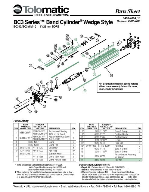
4 – Dual 180° Carrier Option BC310, BC3M10<strong>Parts</strong> <strong>Sheet</strong> #3410-4004_13_BC310ps546156626351505255474645536059257584948203132 332930282524233736353438NOTE: Items shaded cannot be field installedwithout proper assembly fixtures. For repair,return cylinder to <strong>Tol</strong>om<strong>at</strong>icItemBC310PART NO. orConfig. Code2 NDBBC3D10 5 NDBBC3MD10 520 NMBBC3D10BC3M(M)10PART NO. or Config.Code DESCRIPTION QTY.NDBBC3MMD10 5Replacement Dust Band(3410-1239)1NMBBC3MD10 Replacement Magnet Band2NMBBC3MMD10 (3410-1029, 3410-1022)23 3410-2024 End Cap 224 3410-2022 Carrier Cover 125 3410-1019 Ball Return Tube 228 3410-1009 Ball 11229 3410-1510 Wiper 230 3410-2021 4410-1235 Machined Carrier 131 3410-1014 Ball Return 232 3410-1015 Right Ball Race 233 3410-1032 Left Ball Race 234 0910-1357 4905-1012 Socket Head Cap Screw 235 3410-1047 Upper Band Ramp 236 3410-1023 Carrier Way 237 0605-1079 4905-1005 Socket Head Cap Screw 438 3410-1079 PLT, Ball Return 245 3410-1241 Rail Way 246 3410-1020 Machined Rail 25 After configur<strong>at</strong>ion code add: SK_ _ _ (note: <strong>the</strong> letters SK indic<strong>at</strong>estroke, follow <strong>the</strong>se letters with <strong>the</strong> stroke length in decimal inches.) If <strong>the</strong>actu<strong>at</strong>or has <strong>the</strong> dual carrier option add <strong>the</strong> code DC_ _ _ (note: follow<strong>the</strong> letters DC with <strong>the</strong> distance between <strong>the</strong> carriers in decimal inches.)BC310PART NO. orConfig. CodeBC3M(M)10PART NO. or Config.Code DESCRIPTION QTY.Item47 3410-1008 Rail Nut AR48 3410-1229 Button Head Cap Screw AR49 3410-1048 Washer AR50 3410-1049 4410-1049 Pl<strong>at</strong>e, Conn., Dual Carrier 251 2317-1014 4415-1000 Socket Head Cap Screw 852 3410-1054 4410-1054 Pl<strong>at</strong>e, Dual Carrier 153 2317-1014 4415-1000 Socket Head Cap Screw 8KIT 3410-9026 4410-9026Dual 180° Carrier TubeSupport Kit 5AR54 0915-1016 4415-1022 Socket Head Cap Screw 455 3410-1053 Tube Support 1563410-1051 4410-1051 Head, Dual 180° 2– 5410-1051 Head, Dual 180° Parallel 257 3410-1050 PLT, Band Dual Carrier 258 1085-1075 0610-1033 Socket Head Cap Screw 459 3410-1029 4410-1029 Clamp 260 3410-1343 4410-1017 Set Screw 461 3410-1013 4410-1013Silver Nut <strong>for</strong> Slots 90°from Carrier462 0810-1201 4415-1022 SHCS (each end) 263 3410-1052Foot Mount, Dual 180°Carrier1<strong>Tol</strong>om<strong>at</strong>ic • URL: http://www.tolom<strong>at</strong>ic.com • Email: help@tolom<strong>at</strong>ic.com • Fax: (763) 478-8080 • <strong>Tol</strong>l Free: 1-800-328-2174
70 7172<strong>Parts</strong> <strong>Sheet</strong> #3410-4004_13_BC310ps BC310, BC3M10 Options – 5SHOCK STOPPLATE KIT5352 515074TUBESUPPORTKITSHOCKMOUNT KIT736569 606657 5561FOOT MOUNT KIT6768SWITCH KITItemBC310PART NO.BC3M(M)10PART NO. DESCRIPTION QTY.SHOCK STOP PLATE KIT 1KIT 3410-9004 4410-9004 Shock Stop Pl<strong>at</strong>e Kit 150 0610-1045 4415-1021 Impact Bolt 251 3410-1039 4410-1039 Shock Pl<strong>at</strong>e 152 1004-1064 4420-1002 Socket Head Cap Screw 453 0610-1044 4415-1004 Dowel Pin 2Switch Kit55 3410-9999 Switch Mounting Hardw<strong>are</strong> ARPart Number Ordering Config. Code Ordering57No Mounting Hardw<strong>are</strong> or FE conn. includedMounting Hardw<strong>are</strong> & FE conn. includedPart NO. Description Code3600-9084 Switch Only, Reed, Form C, 5m BT3600-9085 Switch Only, Reed, Form C, Male Conn. BM3600-9082 Switch Only, Reed, Form A, 5m RT3600-9083 Switch Only, Reed, Form A, Male Conn. RM3600-9086 Switch Only, Triac, 5m CT3600-9087 Switch Only, Triac, Male Conn. CM3600-9090 Switch Only, Hall-effect, Sinking, 5m KT3600-9091 Switch Only, Hall-effect, Sinking, Male Conn. KM3600-9088 Switch Only, Hall-effect, Sourcing, 5m TT3600-9089 Switch Only, Hall-effect, Sourcing, Male Conn. TM2503-1025 Connector (Female) 5 meter leadNOTE: When ordered by Config. Code Female connector & all mounting hardw<strong>are</strong> is includedSwitch Ordering NOTES:To order field retrofit switch and hardw<strong>are</strong> kits <strong>for</strong> all <strong>Tol</strong>om<strong>at</strong>icactu<strong>at</strong>ors: SW (Then <strong>the</strong> model and bore size, and typeof switch required)Example: SWBC310RT(Hardw<strong>are</strong> and Form A Reed switch with 5 meter lead <strong>for</strong> 1.0"bore BC3 band cylinder)Mounting hardw<strong>are</strong> is required if replacing switch <strong>for</strong> anyactu<strong>at</strong>or manufactured be<strong>for</strong>e 7/1/97Service <strong>Parts</strong> Ordering NOTES:1 Shock Stop Pl<strong>at</strong>e Kit contains shock pl<strong>at</strong>e,impact bolts, screws and dowel pins.2 Foot Mount Kit contains one bracket andmounting hardw<strong>are</strong>.ItemBC310PART NO.BC3M(M)10PART NO. DESCRIPTION QTY.FOOT MOUNT KIT 2KIT 3410-9005 4410-9005 Foot Mount Kit 2 (one end)KIT 3410-9025 4410-9025Dual 180° Carrier Foot MountKit 2 (one end)60 3410-1035 Foot Mount 261 1024-7711 4415-1020 Socket Head Cap Screw 4SHOCK MOUNT KIT WITHOUT SHOCK 3KIT 3410-9003 4410-9003 Shock Mount Kit3 - one side(hardw<strong>are</strong> only, no shock)65 0910-1314 4410-1015 Socket Head Cap Screw 467 3410-1038 4410-1038 Clamping Hook 268 3410-1037 4410-1037 Shock Mount 1SHOCK MOUNT KIT WITH SHOCK 4KIT 3410-9010 4410-9010 Shock Absorber Kit4 - one side(Light Duty Shock)KIT 3410-9013 4410-9013 Shock Absorber Kit4 - one side(Heavy Duty Shock)65 0910-1314 4410-1015 Socket Head Cap Screw 466 2406-1063 4910-1337 Shock, Light Duty 12406-1062 4910-1338 Shock, Heavy Duty 167 3410-1038 4410-1038 Clamping Hook 268 3410-1037 4410-1037 Shock Mount 169 2406-1015 2406-1015 Shock Stop Spacer 1TUBE SUPPORT KIT 5KIT 3410-9006 4410-9006 Tube Support Kit 5AR70 3410-1012 4410-1014 Socket Head Cap Screw 471 3410-1046 4410-1016 Fl<strong>at</strong> Head Cap Screw 472 3410-1013 4410-1013Silver Nut <strong>for</strong> Slots 90° fromCarrier473 3410-1044 3410-1044 Tube Support 274 3410-1775 4410-1708Yellow Nut <strong>for</strong> Slots OppositeCarrier43 Shock Mount Kit Without Shock containsone set of mounting hardw<strong>are</strong>.4 Shock Mount Kit With Shock contains oneshock absorber and mounting hardw<strong>are</strong>.5 Tube Support Kit contains one tube supportand mounting hardw<strong>are</strong>.<strong>Tol</strong>om<strong>at</strong>ic • URL: http://www.tolom<strong>at</strong>ic.com • Email: help@tolom<strong>at</strong>ic.com • Fax: (763) 478-8080 • <strong>Tol</strong>l Free: 1-800-328-2174
70 71726 – Options: Instructions BC310, BC3M10<strong>Parts</strong> <strong>Sheet</strong> #3410-4004_13_BC310psSHOCK STOPPLATE KIT5352 5150TUBESUPPORTKITSHOCKMOUNT KIT736569 606657 5561FOOT MOUNT KIT6768SWITCH KITOPTIONAL ACCESSORY ASSEMBLY INSTRUCTIONS1. SHOCK ABSORBERSSlide a Clamping Hook (67) into each side of <strong>the</strong> Tube (19). Apply Loctite#242 to Screws (65) and secure Shock Mount Pl<strong>at</strong>e (68) to ClampingHooks (67). Thread Shock (66) into Shock Mount Pl<strong>at</strong>e (68). TightenShock (66) to Shock Mount Pl<strong>at</strong>e (68) with Jam Nut. Apply Loctite #242to Screws (52) and secure Shock Pl<strong>at</strong>e (51) to Carrier (30). Insert twoDowel Pins (53) into Shock Pl<strong>at</strong>e (51). Apply Loctite #242 to Impact Bolts(50) and thread into holes in ends of Shock Pl<strong>at</strong>e (51). Torque ImpactBolts (50) to 100-110 in.-lbs.2. FOOT MOUNTSApply Loctite #242 to Screws (61) and secure Foot Mount (60) toeach Head (7).3. TUBE SUPPORTSFour T-Nuts (72) <strong>are</strong> required on each side of <strong>the</strong> Tube (19), twoCrossPortMAINPORTAccessPlugCROSSPORTOpenPluggedStandard Porting(cross ports not functional)CrossPortMAINPORTAccessPlugCrossPortT-Nuts on bottom of Tube and two in lower slots on tube sides. TubeSupports should be secured <strong>at</strong> <strong>the</strong> required distances determined <strong>for</strong><strong>the</strong> applic<strong>at</strong>ion to prevent Tube deflection. Apply Loctite #242 toScrews (71) and secure Tube Supports (73) to tube aligning holes inT-Nuts with holes in Tube Supports.4. SWITCHESOn assembled cylinder, Secure Switch to open port side of cylinderwith a Hardw<strong>are</strong> kit (55) (clamp and screw).NOTE: Form A Reed Switches should not be used in TTL logic circuits.A voltage drop caused by <strong>the</strong> L.E.D. indic<strong>at</strong>or will result.Forapplic<strong>at</strong>ions where TTL circuits <strong>are</strong> used, please contact <strong>the</strong> factory.WARNING: An ohmmeter is recommended <strong>for</strong> testing ReedSwitches. NEVER use an incandescent light bulb as a high currentrush may damage <strong>the</strong> switch.Reed and TRIAC switches <strong>are</strong> only recommended <strong>for</strong> signalling position,not directly powering soleniods. For shifting a solenoid, a relay orresistor is recommended between it and <strong>the</strong> Reed Switch. Switch r<strong>at</strong>ingsmust not be exceeded <strong>at</strong> any time.NOTE: For Hall Effect Switch Magnet, be sure <strong>the</strong> S pole of <strong>the</strong> magnet(indic<strong>at</strong>ed with black dot) is facing toward <strong>the</strong> switch (down).For complete Switch Per<strong>for</strong>mance D<strong>at</strong>a, refer to <strong>the</strong> <strong>Tol</strong>om<strong>at</strong>icFluid Power C<strong>at</strong>alog #9900-4000.MAINPORTMainPortAccessPlugPorted From Left SidePipe Plug RemovedAccessPlugCrossPortCROSSPORTMainPortMAINPORTAccessPlugPipe Plug RemovedPorted From Right SideAccessPlug<strong>Tol</strong>om<strong>at</strong>ic • URL: http://www.tolom<strong>at</strong>ic.com • Email: help@tolom<strong>at</strong>ic.com • Fax: (763) 478-8080 • <strong>Tol</strong>l Free: 1-800-328-2174
LOAD CURRE600300PARt NumBeR 3600-9082 3600-9083 400 3600-9084 3600-9085 3600-9086 100 3600-9087 3600-9088 3600-9089 3600-9090 3600-9091200 REED FORM CLeAD 5m QD* 5m QD* 5m 50 QD* 5m QD* 5m QD*0 CABLe SHIeLDINg Unshielded Shielded† 0 Unshielded Shielded† Unshielded Shielded† Unshielded Shielded† Unshielded Shielded†0 20 40 60 80 100 120 140 1600 20 40 60 80 100 120 140 1600OPERATING TEMPERATURE ( F)OPERATING TEMPERATURE ( F)0 100 PNP 200 (Sourcing) 300 Normally 400 500SWItCHINg LOgIC "A" Normally Open "C" Normally Open or Closed Triac Normally OpenCURRENT D.C Open (mA)NPN (Sinking) Normally OpenmeCHANICAL CONtACtS Single-Pole Single-Throw Single-Pole Double-Throw Single-Pole Single-Throw NO, These Are Solid St<strong>at</strong>e ComponentsLOAD CUREN100200<strong>Parts</strong> <strong>Sheet</strong> #3410-4004_13_BC310ps BC310, BC3M10 Options – 7WIRINg DIAgRAmSCOIL DIReCt Yes Yes Yes —RT & RM DC ReeD, fORm A CT & CM AC ReeD, tRIACPOWeR LeD NoneNoneNoneBROWNNoneNone(+)SIgNAL LeD Red Red tHe RedNOtCHeDLOAD(+)ACOPeRAtINg VOLtAgeREED200 Vdc max. 120 Vdc max. COM 120 Vac max. 5 - 25 Vdc fACe Of tHeSWITCHSWItCH INDICAteS(-)BLUE120Vac MOVOutPut RAtINg(-)Max. —LOAD— 25 Vdc, 200mA tHe dcSeNSINgOR0.6 msec max.SuRfACe ANDBLUE 0.7 msec BROWN max.OPeRAtINg tImeINPUT — < 10 micro muSt sec. fACe(+)BROWN(including bounce) (including bounce)tOWARD tHeOPeRAtINg temPeRAtuRe (+) REED-40°F [-40°C] to 158°F [70°C] 0°F [-18°C] to 150°F mAgNet. [66°C]LOADTRIACReLeASe BLUEtIme SWITCH 1.0 msec. max. SWITCH— —(-)ON tRIP (-) POINt — — 150 Gauss maximumOff tRIP POINt — — 40 Gauss minimumBT & BM DC ReeD, fORm C**POWeR RAtINg (WAttS) 10.0 § 3.0 § § 10.0 5.0COMMONBROWNVOLtAge DROP 2.6 V typical <strong>at</strong> 100 mA NA — — tHe NOtCHeDNORMALLY CLOSEDBLACK REEDReSIStANCe gROOVe IN tHeBLUE SWITCH 0.1 Ω Initial (Max.) — —ACtuAtORNORMALLY OPEN1 Amp <strong>at</strong> 0.5 Amp <strong>at</strong>CuRReNt CONSumPtION —200 mA <strong>at</strong> 25 INDICAteS Vdc tHe86°F [30°C] 140°F [60°C]gROOVe tOTT & TM HALL-effeCt, fReQueNCY SOuRCINg, PNP KT & KM — HALL-effeCt, SINKINg, NPN 47 - 63 Hz — INStALL tHeSWItCH. CONTACTCABLe mIN. BROWN(+)StAtIC (+)0.630" [16mm]BROWN(+)(+)TOLOMATIC IFBeNDHALL-EFFECTSWITCHES ARESOURCING RADIuS BLACK DYNAmICHALL-EFFECTNot RecommendedBLACKREQUIRED ONSWITCHSINKINGBLUE (-)SWITCHBLUE (-)ANOTHER SIDE OFCAutION: DO NOt (-) OVeR tIgHteN SWItCH HARDWARe WHeN (-) INStALLINg!LOADACTUATOR.LOAD** WARNINg: Do not exceed power r<strong>at</strong>ing (W<strong>at</strong>t = Voltage X Amperage). Permanent damage to sensor will occur.Some actu<strong>at</strong>ors may require switch mounting on a specific*QD = Quick Disconnect; Male coupler is loc<strong>at</strong>ed 6" [152mm} from sensor,side of <strong>the</strong> assembly. Call <strong>Tol</strong>om<strong>at</strong>ic <strong>for</strong> details.Female coupler to fl ying lead (part #2503-1025) distance is 197" [5m] also see Cable Shielding specifi c<strong>at</strong>ion aboveRePLACemeNt Of QD SWItCHeS mANufACtuReD BefORe JuLY 1, 1997: It will be necessary to replace or rewire <strong>the</strong> female end coupler.-+VOLTAGE A.C.REE DFORMCREED FORM AINStALLAtION INfORmAtIONCuRReNtBLUEBROWNBLUEBROWNOLDReed Switch Life expectancy: Up toQuick disconnectQuick disconnect SIGNal200,000,000 cycles (depending on load current,duty Female cycle and Connector environmental 5Mconditions)SIGNalWiringWiringBLACKBLACK2503-1025†+Shielded from <strong>the</strong> female quick disconnect coupler to <strong>the</strong> fl ying leads. Shield should be termin<strong>at</strong>ed <strong>at</strong> fl ying lead end.LUBRICATION §Maximum AND current MAINTENANCE500mA (not to exceed 10VA) Refer to Temper<strong>at</strong>ure vs. Current graph installed and Voltage lubric<strong>at</strong>ion. Der<strong>at</strong>ing graph External lubricants must be maintained in a constantsupply or <strong>the</strong> results will be a dry actu<strong>at</strong>or prone to prem<strong>at</strong>ureAll <strong>Tol</strong>om<strong>at</strong>ic BC3 Band Cylinders <strong>are</strong> prelubric<strong>at</strong>ed <strong>at</strong> <strong>the</strong> factory. To§§ensure maximum Maximum cylinder current life, 250mA <strong>the</strong> following (not to exceed guidelines 3VA) Refer should to Temper<strong>at</strong>ure be followed. vs. Current graph wear. and Voltage Der<strong>at</strong>ing graph1. Filtr<strong>at</strong>ion3. Sanitary environmentsWe recommend <strong>the</strong> use of dry, filtered air in our products. “FilteredOil mist lubric<strong>at</strong>ors must dispense “Food Grade” lubricants to <strong>the</strong> airair” means a level of 10 Micron or less. “Dry” means air should be freesupply. Use fluids with ORAL LD50 toxicity r<strong>at</strong>ings of 35 or higherof appreciable amounts of moisture. Regular maintenance of installedsuch as Multi<strong>the</strong>rm® PG-1 or equivalent. Demanding conditions canfilters will generally keep excess moisture in check.require a review of <strong>the</strong> applic<strong>at</strong>ion.2 External Lubric<strong>at</strong>ors (optional)4. Bearing lubric<strong>at</strong>ionThe factory prelubric<strong>at</strong>ion of <strong>Tol</strong>om<strong>at</strong>ic Band Cylinders will provideThe bearing system is prelubric<strong>at</strong>ed <strong>at</strong> <strong>the</strong> factory with a high qualityoptimal per<strong>for</strong>mance without <strong>the</strong> use of external lubric<strong>at</strong>ion. However,No. 2 lithium-soap base grease. Relubric<strong>at</strong>ion is recommendedexternal lubric<strong>at</strong>ors can fur<strong>the</strong>r extend service life of pneum<strong>at</strong>ic actu<strong>at</strong>orsif <strong>the</strong> supply is kept constant.every .5-1 million cycles using a lithium-soap base grease <strong>for</strong> optimalbearing per<strong>for</strong>mance. To relubric<strong>at</strong>e, remove Set Screws (5), andOil lubric<strong>at</strong>ors, (mist or drop) should supply a minimum of 1 drop perClamp Pad (4). Lift back dust band (2) and apply grease directly to20 standard cubic feet per minute to <strong>the</strong> cylinder. As a rule of thumb,<strong>the</strong> st<strong>at</strong>ionary ball ways.double th<strong>at</strong> r<strong>at</strong>e if w<strong>at</strong>er in <strong>the</strong> system is suspected. Demanding conditionsmay require more lubricant.5. Cushion AdjustmentIf lubric<strong>at</strong>ors <strong>are</strong> used, we recommend a non-detergent, 20cP @Adjust <strong>the</strong> cushion needles in <strong>the</strong> cylinder heads c<strong>are</strong>fully to obtain a140˚F 10-weight lubricant. Optimum conditions <strong>for</strong> standard cylindersmooth, hesit<strong>at</strong>ion free deceler<strong>at</strong>ion <strong>for</strong> your particular applic<strong>at</strong>ion. If <strong>the</strong>reoper<strong>at</strong>ion is +32˚ to +150˚F (+0˚ to 65.5˚C).<strong>are</strong> questions on proper adjustment, please consult <strong>Tol</strong>om<strong>at</strong>icNOTE: Use of external lubric<strong>at</strong>ors may wash away <strong>the</strong> factory-3800 County Road 116, Hamel, MN 55340http://www.<strong>Tol</strong>om<strong>at</strong>ic.com • Email: Help@<strong>Tol</strong>om<strong>at</strong>ic.comPhone: (763) 478-8000 • Fax: (763) 478-8080 • <strong>Tol</strong>l Free: 1-800-328-2174© 2012 <strong>Tol</strong>om<strong>at</strong>ic 2012030510598In<strong>for</strong>m<strong>at</strong>ion furnished is believed to be accur<strong>at</strong>eand reliable. However, <strong>Tol</strong>om<strong>at</strong>ic assumes noresponsibility <strong>for</strong> its use or <strong>for</strong> any errors th<strong>at</strong>may appear in this document. <strong>Tol</strong>om<strong>at</strong>ic reserves<strong>the</strong> right to change <strong>the</strong> design or oper<strong>at</strong>ion of <strong>the</strong>equipment described herein and any associ<strong>at</strong>edmotion products without notice. In<strong>for</strong>m<strong>at</strong>ion inthis document is subject to change without notice.


