
Create successful ePaper yourself
Turn your PDF publications into a flip-book with our unique Google optimized e-Paper software.
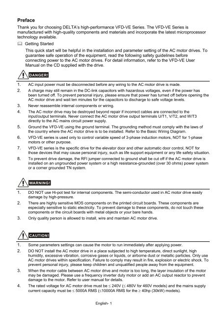
PrefaceThank you for choosing DELTA’s high-performance <strong>VFD</strong>-<strong>VE</strong> Series. The <strong>VFD</strong>-<strong>VE</strong> Series ismanufactured with high-quality components and materials and incorporate the latest microprocessortechnology available. Getting StartedThis <strong>quick</strong> <strong>start</strong> will be helpful in the installation and parameter setting of the AC motor drives. Toguarantee safe operation of the equipment, read the following safety guidelines beforeconnecting power to the AC motor drives. For detail information, refer to the <strong>VFD</strong>-<strong>VE</strong> UserManual on the CD supplied with the drive.DANGER!1. AC input power must be disconnected before any wiring to the AC motor drive is made.2. A charge may still remain in the DC-link capacitors with hazardous voltages, even if the power hasbeen turned off. To prevent personal injury, please ensure that power has turned off before opening theAC motor drive and wait ten minutes for the capacitors to discharge to safe voltage levels.3. Never reassemble internal components or wiring.4. The AC motor drive may be destroyed beyond repair if incorrect cables are connected to theinput/output terminals. Never connect the AC motor drive output terminals U/T1, V/T2, and W/T3directly to the AC mains circuit power supply.5. Ground the <strong>VFD</strong>-<strong>VE</strong> using the ground terminal. The grounding method must comply with the laws ofthe country where the AC motor drive is to be installed. Refer to the Basic Wiring Diagram.6. <strong>VFD</strong>-<strong>VE</strong> series is used only to control variable speed of 3-phase induction motors, NOT for 1-phasemotors or other purpose.7. <strong>VFD</strong>-<strong>VE</strong> series is the specific drive for the elevator door and other automatic door control, NOT forthose devices that may cause personal injury, such as life support equipment or any life safety situation.8. To prevent drive damage, the RFI jumper connected to ground shall be cut off if the AC motor drive isinstalled on an ungrounded power system or a high resistance-grounded (over 30 ohms) power systemor a corner grounded TN system.WARNING!1. DO NOT use Hi-pot test for internal components. The semi-conductor used in AC motor drive easilydamage by high-pressure.2. There are highly sensitive MOS components on the printed circuit boards. These components areespecially sensitive to static electricity. To prevent damage to these components, do not touch thesecomponents or the circuit boards with metal objects or your bare hands.3. Only quality person is allowed to install, wire and maintain AC motor drive.CAUTION!1. Some parameters settings can cause the motor to run immediately after applying power.2. DO NOT install the AC motor drive in a place subjected to high temperature, direct sunlight, highhumidity, excessive vibration, corrosive gases or liquids, or airborne dust or metallic particles. Only useAC motor drives within specification. Failure to comply may result in fire, explosion or electric shock. Toprevent personal injury, please keep children and unqualified people away from the equipment.3. When the motor cable between AC motor drive and motor is too long, the layer insulation of the motormay be damaged. Please use a frequency inverter duty motor or add an AC output reactor to preventdamage to the motor. Refer to user <strong>manual</strong> for details.4. The rated voltage for AC motor drive must be ≤ 240V (≤ 480V for 460V models) and the mains supplycurrent capacity must be ≤ 5000A RMS (≤10000A RMS for the ≥ 40hp (30kW) models).English- 1
SpecificationsVoltage Class230V ClassModel Number <strong>VFD</strong>-XXXV 007 015 022 037 055 075 110 150 185 220 300 370Max. Applicable Motor Output (kW) 0.75 1.5 2.2 3.7 5.5 7.5 11 15 18.5 22 30 37Max. Applicable Motor Output (hp) 1.0 2.0 3.0 5.0 7.5 10 15 20 25 30 40 50Rated Output Capacity (kVA) 1.9 2.7 4.2 6.5 9.5 13 19 25 29 34 46 55Rated Output Current forConstant Torque (A)5.0 7.5 11 17 25 33 49 65 75 90 120 146Rated Output Current forVariable Torque (A)6.25 9.4 13 21 31 41 61 81 93 112 150 182Maximum Output Voltage (V)3-Phase Proportional to Input VoltageOutput Frequency (Hz)0.00~600.00 HzCarrier Frequency (kHz) 15 9 6Output RatingRated Input Current (A) 6.4 9.9 15 21 25 33 52 63 68 79 106 126Rated Voltage/Frequency3-phase 200-240V, 50/60HzVoltage Tolerance ± 10%(180~264 V)Frequency Tolerance± 5%(47~63 Hz)Cooling Method Natural Fan CooledWeight (kg) 2.7 3.2 4.5 6.8 8 10 13 13 13 13 36 36Input RatingVoltage Class460V ClassModel Number <strong>VFD</strong>-XXXV 007 015 022 037 055 075 110 150 185 220 300 370 450 550 750Max. Applicable Motor Output (kW) 0.75 1.5 2.2 3.7 5.5 7.5 11 15 18.5 22 30 37 45 55 75Max. Applicable Motor Output (hp) 1.0 2.0 3.0 5.0 7.5 10 15 20 25 30 40 50 60 75 100Rated Output Capacity (kVA) 2.3 3.2 4.2 6.3 9.9 14 18 24 29 34 46 56 69 80 100Rated Output Current forConstant Torque (A)3.0 4.2 6.0 8.5 13 18 24 32 38 45 60 73 91 110 150Rated Output Current forVariable Torque (A)3.8 5.3 7.5 10 16 22 30 40 47 56 75 91 113 138 188Maximum Output Voltage (V)3-phase Proportional to Input VoltageOutput Frequency (Hz)0.00~600.00 HzCarrier Frequency (kHz) 15 9 6Rated Input Current (A)3-phase 380~480V4.0 5.8 7.4 9.9 12 17 25 27 35 42 56 67 87 101 122Rated Voltage3-phase 380 to 480 VVoltage Tolerance ± 10%(342~528 V)Frequency Tolerance± 5%(47~63 Hz)Cooling Method Natural Fan CooledWeight (kg) 2.7 3.2 4.5 6.8 8 10 13 13 13 13 36 36 36 50 50Output RatingInput RatingControl CharacteristicsControl SystemStart TorqueSpeed Control RangeSpeed Control ResolutionSpeed Response AbilityMax. Output FrequencyGeneral Specifications1 V/f curve; 2 V/f+PG; 3 SVC; 4 FOC+PG; 5 TQR+PGStarting torque is 150% at 0.5Hz and 0Hz with FOC + PG control mode1:100 Sensorless vector (up to 1:1000 when using PG card)± 0.5% Sensorless vector (up to ± 0.02% when using PG card)English- 25Hz (up to 30Hz for vector control)0.00 to 600.00HzOutput Frequency Accuracy Digital command ± 0.005%, analog command ± 0.5%Frequency SettingDigital command ± 0.01Hz, analog command: 1/4096(12-bit) of the max. outputResolutionfrequencyTorque LimitMax. is 200% torque currentTorque Accuracy ± 5%Accel/Decel Time0.00 to 600.00/0.0 to 6000.0 secondsV/f CurveAdjustable V/f curve using 4 independent points and square curveFrequency Setting Signal± 10V, 4~20mA, pulse inputBrake Torque About 20%Motor ProtectionElectronic thermal relay protectionha
EnvironmentalConditionsGeneral SpecificationsOver-current Protection The current forces 220% of the over-current protection and 300% of the ratedcurrentGround Leakage CurrentProtectionHigher than 50% X rated currentOverload AbilityConstant torque: 150% for 60 seconds, variable torque: 200% for 3 secondsOver-voltage Protection Over-voltage level: Vdc > 400/800V; low-voltage level: Vdc < 200/400VOver-voltage Protection forthe Input PowerVaristor (MOV)Over-temperature ProtectionCompensation for theMomentory Power LossProtection LevelOperation TemperatureStorage TemperatureAmbient HumidityVibrationInstallation LocationApprovalsDescription of the Digital keypad KPV-CE01Built-in temperature sensorUp to 5 seconds for parameter settingNEMA 1/IP21-10 o C to 40 o C-20 o C to 60 o CBelow 90% RH (non-condensing)9.80665m/s 2 (1G) less than 20Hz, 5.88m/s 2 (0.6G) at 20 to 50HzAltitude 1,000 m or lower, keep from corrosive gasses, liquid and dustFHUKPV-CE01EXTPULED DisplayDisplay frequency, current, voltageand error, etc.Part NumberStatus DisplayDisplay of driver statusMODE Selection KeyPress this key to view differentoperating valuesJOGPULeft Keymoves cursor to the leftRight KeyMoves the cursor rightFWD/REV Direction KeyRUN keyRUNSTOPRESETSTOP/RESETEnglish- 3
Basic Wiring DiagramUsers must connect wiring according to the following circuit diagram shown below.DC choke(optional)Br ak e res istor(optional)JumperFuse/NFB(No Fuse Breaker)R(L1)+1 +2/B1 B2 -R(L1) U(T1)S(L2)S(L2) V(T2)T(L3)T(L3) W(T3)ERecommended CircuitSAEwhen power supplyis turned OFF by aMC RBRAfault output.If the fault occurs, the OFF ONRCRBcontact will be ON to turnMCoff the power and protect the power system.RC+24VFactory setting:FWD/STOPMRAFWDSINK ModeREV/STOPSinkREVSw1Multi-step 1MRCFactoryMI1SourcesettingMulti-step 2MO1Please refer toMI2Multi-step 3Figure 3 for wiringMI3of SINK mode and Multi-step 4SOURCEmode.MI4No functionMI5MO2No functionMI6Digital Signal Common* Don't apply the mains voltage directlyDCMMCMto above terminals.EDFMACI current/voltage selection+10VACI Switch3Power supplyMake sure that power is OFF+10V 20mAbefore changing the switch 5K 2AVIMaster Frequencysetting.DCM10 to 10V 47k0-20mA 0-10VACI4~20mA/0~10VAUI-10~+10VACMAnalog Signal CommonEAnalog Multi-function Output TerminalAFM analog output selectionAFM SwitchMake sure that power is OFFbefore changing the switchsetting.0-10V 0-20mAAFM 0~10VDC/2mAACMAnalog Signal commonEFor each model, it may havedifferent wiring. Refer to thefollowing diagram for details.MotorIM3~Multi-function contact output 1(relay)factory setting: fault indicationMulti-function contact output 2(relay)48VDC 50mAfactory setting:indicates that it is runningMulti-function contact output 3(photocoupler)Multi-function contact output 4(photocoupler)Multi-functionPhotocoupler OutputDigital Frequency OutputTer minalfactory setting: 1:1Duty=50%, 10VDCDigital Signal CommonDFM output signal selectionDFM SwitchMake sure that power is OFFbefore changing the switchsetting.OCTPRS-485 serial communication1: +EV2: GND For communication,3: SG- it needs to use4: SG+ <strong>VFD</strong>-USB01/IFD85005: NC to connect to PC.6: NCMain circuit (power) terminals Control circuit terminals Shielded leads & CableNOTEThe brake resistor is built-in to model <strong>VFD</strong>110V43B.English- 6
Figure 1 for models of <strong>VFD</strong>-<strong>VE</strong> Series (15 HP and below)<strong>VFD</strong>007V23A/43A-2, <strong>VFD</strong>015V23A/43A-2,<strong>VFD</strong>022V23A/43A-2, <strong>VFD</strong>037V23A/43A-2,<strong>VFD</strong>055V23A/43A-2, <strong>VFD</strong>075V23A/43A-2,<strong>VFD</strong>110V43B-2, <strong>VFD</strong>110V23A/43A-2DC choke(optional)Brake resistor(optional)Jumper+1+2/B1Figure 2 for models of <strong>VFD</strong>-<strong>VE</strong> Series (20HP and above)<strong>VFD</strong>150V23A/43A-2, <strong>VFD</strong>185V23A/43A-2, <strong>VFD</strong>220V23A/43A-2,<strong>VFD</strong>300V43A-2, <strong>VFD</strong>370V43A-2, <strong>VFD</strong>450V43A-2, <strong>VFD</strong>300V23A-2,<strong>VFD</strong>370V23A-2, <strong>VFD</strong>550V43C-2, <strong>VFD</strong>750V43C-2DC choke(optional) Brake Unit(optional)B2-<strong>VFD</strong>BBrake resistor (optional)Jumper+1+2-(minus sign)Figure 3 Wiring for SINK(NPN) mode and SOURCE(PNP) modeSINK(NPN) ModeSOURCE(PNP) ModeSinkSW1SourceFactorysettingFWD/STOPREV/STOPMulti-step1Multi-step2Multi-step3Multi-step4No FunctionNo FunctionDigital Signal Common*Don't apply the mains voltage directlyto above terminals.+24VFWDREVMI1MI2MI3MI4MI5MI6DCMESinkSW1SourceFactorysettingFWD/STOPREV/STOPMulti-step1Multi-step2Multi-step3Multi-step4No FunctionNo Function*Don't apply the mains voltage directlyto above terminals.+24VFWDREVMI1MI2MI3MI4MI5MI6DCMETerminal ExplanationsTerminal SymbolExplanation of Terminal FunctionR, S, T R/L1, S/L2, T/L3 AC line input terminals (1-phase/3-phase)U, V, W U/T1, V/T2, W/T3AC drive output terminals for connecting 3-phaseinduction motorP1, P2 +1, +2 Connections for DC Choke (optional)P-B, P2/B1~B2 +2/B1~B2 Connections for Brake Resistor (optional)P2~N, P2/B1~N +2~(-), +2/B1~(-) Connections for External Brake Unit (<strong>VFD</strong>B series)Earth connection, please comply with local regulations.English- 7
Control Terminals ExplanationsTerminalSymbolFWDREVTerminal FunctionForward-Stop CommandReverse-Stop CommandMI1 Multi-function Input 1ON:OFF:ON:OFF:Factory Settings (SINK)ON: Connect to DCMRun in FWD directionStop acc. to Stop MethodRun in REV directionStop acc. to Stop MethodMI2 Multi-function Input 2MI3 Multi-function Input 3MI4 Multi-function Input 4MI5 Multi-function Input 5MI6 Multi-function Input 6DFMDigital Frequency Meter(Open Collector Output)DFM-DCM Max: 48V50mAinternal circuit+24V DC Voltage SourceDCMRARBRCMRAMRCMO150%100%Digital Signal CommonMulti-function Relay Output 1(N.O.) aMulti-function Relay Output 1(N.C.) bMulti-function Relay CommonMulti-function Relay Output 2(N.O.) aMulti-function Relay CommonMulti-function Output 1(Photocoupler)Refer to Pr.02-01 to Pr.02-06 for programmingthe Multi-function Inputs.ON: the activation current is 6.5mA. OFF:leakage current tolerance is 10μA.Pulse voltage output monitor signal, proportionalto output frequencyDuty-cycle: 50%Ratio:Pr.02-18Min. load:4.7kΩMax. current: 50mAMax. voltage:Jumper:+24VDC, 80mAused for SOURCE mode.48VDC.DFM jumper, factorysetting is OCCommon for digital inputs and used for SINKmode.Resistive Load:5A(N.O.)/3A(N.C.) 240VAC5A(N.O.)/3A(N.C.) 24VDCInductive Load:1.5A(N.O.)/0.5A(N.C.) 240VAC1.5A(N.O.)/0.5A(N.C.) 24VDCTo output monitor signal, including in operation,frequency arrival, overload and etc.Refer to Pr.02-11~02-12 for programmingMaximum 48VDC, 50mARefer to Pr.02-13 to Pr.02-14 for programmingMO1~MO2-DCMMax: 48Vdc50mAMO2Multi-function Output 2(Photocoupler)MO1~MO2MCMInternal CircuitEnglish- 8
IM3Power Terminals and Control TerminalsFrame Power range ModelsB (B1) 1-3hp (0.75-2.2kW)<strong>VFD</strong>007V23A/43A-2, <strong>VFD</strong>015V23A/43A-2,<strong>VFD</strong>022V23A/43A-2B (B2) 5hp (3.7kW)<strong>VFD</strong>037V23A/43A-2C 7.5-15hp (5.5-11kW) <strong>VFD</strong>055V23A/43A-2, <strong>VFD</strong>075V23A/43A-2, <strong>VFD</strong>110V43B-2D15-30hp (11-22kW)E (E1) 40-60hp (30-45kW)E (E2) 40-100hp (30-75kW)<strong>VFD</strong>110V23A/43A-2, <strong>VFD</strong>150V23A/43A-2,<strong>VFD</strong>185V23A/43A-2, <strong>VFD</strong>220V23A/43A-2<strong>VFD</strong>300V43A-2, <strong>VFD</strong>370V43A-2, <strong>VFD</strong>450V43A-2<strong>VFD</strong>300V23A-2, <strong>VFD</strong>370V23A-2, <strong>VFD</strong>550V43C-2,<strong>VFD</strong>750V43C-2Control TerminalsFrame Torque WireB, C, D, E, E1 8 kgf-cm (6.9 in-lbf) 22-14 AWG (0.3-2.1mm 2 )Frame BMain circuit terminalsR/L1, S/L2, T/L3, U/T1, V/T2, W/T3,, +1, +2/B1, -, B2+1 +2 B1 - B2 U/T1 V/T2 W/T3Screw Torque :18Kgf-cmWire Gauge :18~10AWGModels Wire Torque Wire Type<strong>VFD</strong>007V23A-2<strong>VFD</strong>007V43A-2<strong>VFD</strong>015V23A-2<strong>VFD</strong>015V43A-2<strong>VFD</strong>022V23A-2<strong>VFD</strong>022V43A-2<strong>VFD</strong>037V23A-2<strong>VFD</strong>037V43A-214-10 AWG(2.1-5.3mm 2 )18kgf-cm(15.6in-lbf)Strandedcopper only,75 o CR/L1 S/L2 T/L3Frame CMain circuit terminalsR/L1, S/L2, T/L3, U/T1, V/T2, W/T3,, +1, +2/B1, -, B2Models Wire Torque Wire Type<strong>VFD</strong>055V23A-2<strong>VFD</strong>075V23A-2<strong>VFD</strong>110V43B-2<strong>VFD</strong>055V43A-2<strong>VFD</strong>075V43A-212-8 AWG(3.3-8.4mm 2 )30kgf-cm(26in-lbf)Strandedcopper only,75 o CPOWERMOTOREnglish- 10
POWERScrew Torque:200kgf-cm (173in-lbf)POWERALARMIM33IM MOTORFrame DMain circuit terminalsR/L1, S/L2, T/L3, U/T1, V/T2, W/T3, , +1, +2, -Models Wire Torque Wire Type<strong>VFD</strong>110V23A-2<strong>VFD</strong>110V43A-2<strong>VFD</strong>150V43A-2<strong>VFD</strong>150V23A-2<strong>VFD</strong>185V23A-2<strong>VFD</strong>185V43A-2<strong>VFD</strong>220V43A-2<strong>VFD</strong>220V23A-28-2 AWG(8.4-33.6mm 2 )30kgf-cm(26in-lbf)Strandedcopper only,75 o CR/L1 S/L2 T/L3 +1 +2 -POWER DC ( + ) DC (-)V/T2 W/T3MOTORFrame EMain circuit terminalsR/L1, S/L2, T/L3, U/T1, V/T2, W/T3, , +1, +2, -CHARGES/L2 R/L1 T/L3 +2 +1 U/T1 V/T2W/T3Models Wire Torque Wire Type<strong>VFD</strong>300V43A-2<strong>VFD</strong>370V43A-2<strong>VFD</strong>450V43A-2<strong>VFD</strong>300V23A-2<strong>VFD</strong>370V23A-2<strong>VFD</strong>550V43C-2<strong>VFD</strong>750V43C-257kgf-cm(49in-lbf)4-2 AWG(21.2-33.6mm 2 ) 200kgf-cm(173in-lbf)Strandedcopper only,75 o CNOTE To connect 6 AWG (13.3 mm2) wires, use Recognized Ring Terminals.Summary of Parameter Settings: The parameter can be set during operation.Pr. Explanation SettingsGroup 0 System ParametersFactorySettingVF VFPG SVC FOCPG TQRPGIdentity Code of the AC00-00 motor driveRead-only 0 ○ ○ ○ ○ ○Rated Current Display of Read-only 0 ○ ○ ○ ○ ○00-01 the AC motor drive0: No function0 ○ ○ ○ ○ ○1: Read only2: Enable group 11 parameters setting00-02 Parameter Reset8: Keypad lock9: All parameters are reset to factory settings (50Hz,220V/380V)10: All parameters are reset to factory settings (60Hz,220V/440V)00-03 Start-up Display Selection 1: Display the actual output frequency (LED H)2: Multifunction display, see Pr.00-04 (LED U)0: Display the frequency command value (LED F)0 ○ ○ ○ ○ ○3: Display the output current (A)English- 11
Pr. Explanation Settings00-04Content of Multi FunctionDisplay0: Display output current (A)1: Display counter value (C)2: Display output frequency (H)3: Display DC-BUS voltage ( u )4: Display output voltage (E)5: Output power factor angle (n)6: Display output power (kW)7: Display actual motor speed (HU)8: Display estimate output torque (kg-m)9: Display PG position (G) (refer to Pr.10-00 and Pr.10-01)10: Display PID feedback11: Display AVI (%)12: Display ACI (%)13: Display AUI (%)14: Display the temperature of heat sink (°C)15: Display the temperature of IGBT (°C)16: The status of digital input (ON/OFF)17: The status of digital output (ON/OFF)18: Multi-step speed19: The corresponding CPU pin status of digital input20: The corresponding CPU pin status of digital output21: Number of actual motor revolution (PG1 of PG card)22: Pulse input frequency (PG2 of PG card)23: Pulse input position (PG2 of PG card)FactorySettingVF VFPG SVC FOCPG TQRPG0 ○ ○ ○ ○ ○00-05 User-Defined Coefficient K Digit 4: decimal point number (0 to 3)0 ○ ○ ○ ○ ○Digit 0-3: 40 to 999900-06 Software Version Read-only #.# ○ ○ ○ ○ ○00-07 Password Input 1 to 9998 and 10000 to 655350 ○ ○ ○ ○ ○0 to 2: times of wrong password00-08 Password Set 0: No password set or successful input in Pr.00-071 to 9998 and 10000 to 655350 ○ ○ ○ ○ ○1: Password has been set00-09 Energy Saving Gain 10~1000 % 100% ○0: V/f Control0 ○ ○ ○ ○ ○1: V/f Control + Encoder (VFPG)00-10 Control Method2: Sensorless vector control (SVC)3: FOC vector control + Encoder (FOCPG)4: Torque control + Encoder (TQRPG)0: V/f curve determined by group 010 ○ ○00-11 V/f Curve Selection 1: 1.5 power curve2: Square curve00-1200-1300-14Constant/Variable TorqueSelectionOptimalAcceleration/DecelerationSettingTime Unit forAcceleration/Decelerationand S Curve00-15 Reserved00-16 Reserved0: Constant Torque (100%)1: Variable Torque (125%)0: Linear accel./decel. I1: Auto accel., linear decel.2: Linear accel., auto decel.3: Auto accel./decel.4: Stall prevention by auto accel./decel. (limited by 01-12to 01-21)0: Unit: 0.01 second1: Unit: 0.1 second0 ○ ○ ○ ○0 ○ ○ ○ ○0 ○ ○ ○ ○00-17 Carrier Frequency 1~15KHz 10 ○ ○ ○ ○ ○0: Enable AVR0 ○ ○ ○ ○ ○Auto Voltage Regulation00-18 1: Disable AVR(AVR) Function2: Disable AVR when deceleration stopAuto Energy-saving 0: Disable0 ○ ○ ○ ○00-19 Operation1: Enable00-2000-21Source of the MasterFrequency CommandSource of the OperationCommand0: Digital keypad (KPV-CE01)1: RS-485 serial communication2: External analog input (Pr. 03-00)3: External UP/DOWN terminal4: Pulse input without direction command (Pr.10-15without direction)5: Pulse input with direction command (Pr.10-15)0: Digital keypad (KPV-CE01)1: External terminals. Keypad STOP disabled.2: RS-485 serial communication (RJ-11). Keypad STOPdisabled.0 ○ ○ ○ ○0 ○ ○ ○ ○ ○English- 12
FactoryPr. Explanation SettingsVF VFPG SVC FOCPG TQRPGSetting13: Reel diameter ○ ○ ○ ○ ○14: PID target value of tension (tension closed-loop) ○ ○ ○ ○ ○15: Tension setting (tension open-loop) ○16: Zero-speed tension ○17: Tension taper ○03-03 Analog Input Bias 1 (AVI) -100.0~100.0% 0 ○ ○ ○ ○ ○03-04 Analog Input Bias 2 (ACI) -100.0~100.0% 0 ○ ○ ○ ○ ○03-05 Analog Input Bias 3 (AUI) -100.0~100.0% 0 ○ ○ ○ ○ ○Positive/negative Bias 0: Zero bias0 ○ ○ ○ ○ ○03-06Mode (AVI)1: Lower than bias=biasPositive/negative Bias 2: Greater than bias=bias0 ○ ○ ○ ○ ○03-07Mode (ACI)3: The absolute value of the bias voltage while servingPositive/negative Bias as the center0 ○ ○ ○ ○ ○03-08Mode (AUI)4: Serve bias as the center03-09 Analog Input Gain 1 (AVI) -500.0~500.0% 100.0 ○ ○ ○ ○ ○03-10 Analog Input Gain 2 (ACI ) -500.0~500.0% 100.0 ○ ○ ○ ○ ○03-11 Analog Input Gain 3 (AUI) -500.0~500.0% 100.0 ○ ○ ○ ○ ○ACI/AVI2 Selection 0: ACI0 ○ ○ ○ ○ ○03-121: AVI 2Analog Input Delay Time0.01 ○ ○ ○ ○ ○03-13 0.00~2.00 sec(AVI)Analog Input Delay Time0.01 ○ ○ ○ ○ ○03-14 0.00~2.00 sec(ACI)Analog Input Delay Time0.01 ○ ○ ○ ○ ○03-15 0.00~2.00 sec(AUI)Addition Function of the 0: Disable (AVI, ACI, AUI)○ ○ ○ ○ ○03-16Analog Input1: EnableLoss of the ACI Signal 0: Disable0 ○ ○ ○ ○ ○03-171: Continue operation at the last frequency2: Decelerate to stop3: Stop immediately and display E.F.03-18 Analog Output Selection 1 0: Output frequency (Hz) 0 ○ ○ ○ ○ ○1: Frequency command (Hz) ○ ○ ○ ○ ○03-21 Analog Output Selection 2 2: Motor speed (Hz) ○ ○ ○ ○ ○3: Output current (rms) ○ ○ ○ ○ ○03-24 Analog Output Selection 3 4: Output voltage ○ ○ ○ ○ ○5: DC Bus Voltage ○ ○ ○ ○ ○6: Power factor ○ ○ ○ ○ ○7: Power ○ ○ ○ ○ ○8: Output torque ○ ○ ○ ○ ○9: AVI ○ ○ ○ ○ ○10: ACI ○ ○ ○ ○ ○11: AUI ○ ○ ○ ○ ○12: q-axis current ○ ○ ○ ○ ○13: q-axis feedback value ○ ○ ○ ○ ○14: d-axis current ○ ○ ○ ○ ○15: d-axis feedback value ○ ○ ○ ○ ○16: q-axis voltage ○ ○ ○ ○ ○17: d-axis voltage ○ ○ ○ ○ ○18: Torque command ○ ○ ○ ○ ○19: Pulse frequency command ○ ○ ○ ○ ○Analog Output Gain 103-190~200.0% 100.0 ○ ○ ○ ○ ○Analog Output Value in 0: Absolute value in REV direction0 ○ ○ ○ ○ ○03-20REV Direction 11: Output 0V in REV direction2: Enable output voltage in REV directionAnalog Output Gain 203-220~200.0% 100.0 ○ ○ ○ ○ ○Analog Output Value in 0: Absolute value in REV direction0 ○ ○ ○ ○ ○03-23REV Direction 21: Output 0V in REV direction2: Enable output voltage in REV directionAnalog Output Gain 303-250~200.0% 100.0 ○ ○ ○ ○ ○Analog Output Value in 0: Absolute value in REV direction0 ○ ○ ○ ○ ○03-26REV Direction 31: Output 0V in REV direction2: Enable output voltage in REV directionEnglish- 17
Pr. Explanation SettingsGroup 4 Multi-Step Speed ParametersFactorySettingVF VFPG SVC FOCPG TQRPG1st Step Speed Frequency 0.00~600.00Hz04-000.00 ○ ○ ○ ○2nd Step Speed Frequency 0.00~600.00Hz04-010.00 ○ ○ ○ ○3rd Step Speed Frequency 0.00~600.00Hz04-020.00 ○ ○ ○ ○4th Step Speed Frequency 0.00~600.00Hz04-030.00 ○ ○ ○ ○5th Step Speed Frequency 0.00~600.00Hz 0.00 ○ ○ ○ ○04-046th Step Speed Frequency 0.00~600.00Hz 0.00 ○ ○ ○ ○04-057th Step Speed Frequency 0.00~600.00Hz 0.00 ○ ○ ○ ○04-068th Step Speed Frequency 0.00~600.00Hz 0.00 ○ ○ ○ ○04-079th Step Speed Frequency 0.00~600.00Hz 0.00 ○ ○ ○ ○04-0810th Step Speed0.00~600.00Hz 0.00 ○ ○ ○ ○04-09Frequency11th Step Speed0.00~600.00Hz 0.00 ○ ○ ○ ○04-10Frequency12th Step Speed0.00~600.00Hz 0.00 ○ ○ ○ ○04-11Frequency13th Step Speed0.00~600.00Hz 0.00 ○ ○ ○ ○04-12Frequency14th Step Speed0.00~600.00Hz 0.00 ○ ○ ○ ○04-13Frequency15th Step Speed0.00~600.00Hz 0.00 ○ ○ ○ ○04-14FrequencyMulti-position 104-150~65535 0 ○ ○Multi-position 204-160~65535 0 ○ ○Multi-position 304-170~65535 0 ○ ○Multi-position 404-180~65535 0 ○ ○Multi-position 504-190~65535 0 ○ ○Multi-position 604-200~65535 0 ○ ○Multi-position 704-210~65535 0 ○ ○Multi-position 804-220~65535 0 ○ ○Multi-position 904-230~65535 0 ○ ○Multi-position 1004-240~65535 0 ○ ○Multi-position 1104-250~65535 0 ○ ○Multi-position 1204-260~65535 0 ○ ○Multi-position 1304-270~65535 0 ○ ○Multi-position 1404-280~65535 0 ○ ○Multi-position 1504-290~65535 0 ○ ○Group 5 Motor Parameters05-00 Motor Auto Tuning 0: No function1: Rolling test2: Static Test0 ○ ○ ○3: Reserved05-01 Full-load Current of Motor 1 40-100% #.## ○ ○ ○ ○ ○Rated power of Motor 105-020~655.35 #.## ○ ○ ○Rated speed of Motor 1 0~655351710 ○ ○ ○ ○05-03(rpm)1710 (60Hz, 4 poles), 1410 (50Hz, 4 poles)05-04 Number of Motor Poles 1 2~20 4 ○ ○ ○ ○ ○05-05 No-load Current of Motor 1 0-factory setting of Pr.05-01 #.## ○ ○ ○ ○05-06 Rotor Resistance R1 of 0~65.535Ω #.### ○ ○ ○Motor 105-07 Rr of Motor 1 0~65.535Ω #.### ○ ○ ○05-08 Lm of Motor 1 0~6553.5mH #.# ○ ○ ○05-09 Lx of Motor 1 0~6553.5mH #.# ○ ○ ○05-10 Motor 1/Motor 2 Selection 1: Motor 11 ○ ○ ○ ○ ○2: Motor 2Frequency for Y-0.00~600.00Hz 60.00 ○ ○ ○ ○05-11connection/ Δ−connectionSwitchEnglish- 18
Pr. Explanation Settings05-12 Y-connection/Δ−connection Switch0: Disable1: EnableFactorySettingVF VFPG SVC FOCPG TQRPG0 ○ ○ ○ ○05-13 Full-load Current of Motor 2 40-100% #.## ○ ○ ○ ○ ○Rated Power of Motor 205-140~655.35 #.## ○ ○ ○Rated Speed of Motor 2 0~65535 1710 ○ ○ ○ ○05-15(rpm)05-16 Number of Motor Poles 2 2~20 4 ○ ○ ○ ○ ○05-17 No-load Current of Motor 2 0- factory setting of Pr.05-01 #.## ○ ○ ○ ○05-18 Rs of Motor 2 0~65.535Ω #.### ○ ○ ○05-19 Rr of Motor 2 0~65.535Ω #.### ○ ○ ○05-20 Lm of Motor 2 0~6553.5mH #.# ○ ○ ○05-21 Lx of Motor 2 0~6553.5mH #.# ○ ○ ○Torque Compensation 0.001~10.000sec 0.020 ○ ○ ○05-22Time Constant05-2305-24Slip Compensation TimeConstantTorque CompensationGain0.001~10.000sec 0.100 ○ ○0~10 0 ○ ○Slip Compensation Gain 0.00~10.00 0.00 ○ ○05-25Slip Deviation Level 0~1000% (0: disable) 0 ○ ○ ○05-2605-27Detection Time of SlipDeviation0.0~10.0 sec 1.0 ○ ○ ○0: Warn and keep operation0 ○ ○ ○05-28 Over Slip Treatment 1: Warn and ramp to stop2: Warn and coast to stopHunting Gain05-290~10000 (0: disable) 2000 ○ ○ ○Delay Time for Y-0~60.000 sec 0.200 ○ ○ ○ ○05-30connection/Δ −connection05-31 Accumulative Motor 00~1439 0 ○ ○ ○ ○ ○Operation Time (Min.)05-32 Accumulative MotorOperation Time (day)00~65535 0 ○ ○ ○ ○ ○Group 6 Protection Parameters160.0~220.0Vdc 180.0 ○ ○ ○ ○ ○06-00 Low Voltage Level 320.0~440.0Vdc 360.0 ○ ○ ○ ○ ○06-01Over-voltage StallPrevention0.0: Disable350.0~450.0Vdc 380.0 ○ ○ ○ ○ ○700.0~900.0Vdc 760.0 ○ ○ ○ ○ ○Phase-loss Protection 0: Warn and keep operation0 ○ ○ ○ ○ ○06-021: Warn and ramp to stop2: Warn and coast to stopOver-current Stall00~250% 170 ○ ○ ○06-03Prevention duringAccelerationOver-current Stall00~250% 170 ○ ○ ○06-04Prevention duringOperationAccel./Decel. Time 0: by current accel/decel time0 ○ ○ ○06-05Selection of Stall1: by the 1st accel/decel timePrevention at constant 2: by the 2nd accel/decel timespeed3: by the 3rd accel/decel time4: by the 4th accel/decel time5: by auto accel/decel time06-06Over-torque DetectionSelection (OT1)Over-torque Detection06-07Level (OT1)Over-torque Detection06-08Time (OT1)0: disable1: over-torque detection during constant speedoperation, continue to operate after detection2: over-torque detection during constant speedoperation, stop operation after detection3: over-torque detection during operation, continue tooperate after detection4: over-torque detection during operation, stop operationafter detection0 ○ ○ ○ ○ ○10~250% 150 ○ ○ ○ ○ ○0.0~60.0 sec 0.1 ○ ○ ○ ○ ○English- 19
Pr. Explanation Settings06-09Over-torque DetectionSelection (OT2)0: disable1: over-torque detection during constant speedoperation, continue to operate after detection2: over-torque detection during constant speedoperation, stop operation after detection3: over-torque detection during operation, continue tooperate after detection4: over-torque detection during operation, stop operationafter detectionFactorySettingVF VFPG SVC FOCPG TQRPG0 ○ ○ ○ ○ ○Over-torque Detection 10~250% 150 ○ ○ ○ ○ ○06-10Level (OT2)Over-torque Detection 0.0~60.0 sec 0.1 ○ ○ ○ ○ ○06-11Time (OT2)Current Limit 0~250% 150 ○ ○06-12Electronic Thermal Relay 0: Inverter motor2 ○ ○ ○ ○ ○06-13Selection (Motor 1) 1: Standard motor2: DisableElectronic Thermal 30.0~600.0 sec 60.0 ○ ○ ○ ○ ○06-14Characteristic for Motor 1Heat Sink Over-heat (OH) 0.0~110.0 °C 85.0 ○ ○ ○ ○ ○06-15WarningStall Prevention Limit Level 0~100% (refer to Pr.06-03, Pr.06-04) 50 ○ ○ ○06-1606-17 Present Fault Record 0: No fault 0 ○ ○ ○ ○ ○1: Over-current during acceleration (ocA) ○ ○ ○ ○ ○06-18Second Most Recent Fault 2: Over-current during deceleration (ocd) 0 ○ ○ ○ ○ ○Record 3: Over-current during constant speed (ocn) ○ ○ ○ ○ ○4: Ground fault (GFF) ○ ○ ○ ○ ○06-19Third Most Recent Fault 5: IGBT short-circuit (occ) 0 ○ ○ ○ ○ ○Record 6: Over-curent at stop (ocS) ○ ○ ○ ○ ○7: Over-voltage during acceleration (ovA) ○ ○ ○ ○ ○06-20 Fourth Most Recent Fault 8: Over-voltage during deceleration (ovd) 0 ○ ○ ○ ○ ○Record 9: Over-voltage during constant speed (ovn) ○ ○ ○ ○ ○10: Over-voltage at stop (ovS) ○ ○ ○ ○ ○11: Low-voltage during acceleration (LvA) ○ ○ ○ ○ ○06-21 Fifth Most Recent Fault 12: Low-voltage during deceleration (Lvd) ○ ○ ○ ○ ○Record 13: Low-voltage during constant speed (Lvn) ○ ○ ○ ○ ○14: Low-voltage at stop (LvS) 0 ○ ○ ○ ○ ○15: Phase loss (PHL) ○ ○ ○ ○ ○16: IGBT heat sink over-heat (oH1) ○ ○ ○ ○ ○06-22 Sixth Most Recent Fault 17: Heat sink over-heat (oH2)(for 40HP above) 0 ○ ○ ○ ○ ○Record 18: TH1 open loop error (tH1o) ○ ○ ○ ○ ○19: TH2 open loop error (tH2o) ○ ○ ○ ○ ○20: Fan error signal output ○ ○ ○ ○ ○21: over-load (oL) (150% 1Min) ○ ○ ○ ○ ○22: Motor 1 over-load (EoL1) ○ ○ ○ ○ ○23: Motor 2 over-load (EoL2) ○ ○ ○ ○ ○24: Motor PTC overheat (oH3) ○ ○ ○ ○ ○25: Fuse error (FuSE) ○ ○ ○ ○ ○26: over-torque 1 (ot1) ○ ○ ○ ○ ○27: over-torque 1 (ot2) ○ ○ ○ ○ ○28: Reserved29: Reserved30: Memory write-in error (cF1) ○ ○ ○ ○ ○31: Memory read-out error (cF2) ○ ○ ○ ○ ○32: Isum current detection error (cd0) ○ ○ ○ ○ ○33: U-phase current detection error (cd1) ○ ○ ○ ○ ○34: V-phase current detection error (cd2) ○ ○ ○ ○ ○35: W-phase current detection error (cd3) ○ ○ ○ ○ ○36: Clamp current detection error (Hd0) ○ ○ ○ ○ ○37: Over-current detection error (Hd1) ○ ○ ○ ○ ○38: Over-voltage detection error (Hd2) ○ ○ ○ ○ ○39: Ground current detection error (Hd3) ○ ○ ○ ○ ○40: Auto tuning error (AuE) ○ ○ ○41: PID feedback loss (AFE) ○ ○ ○ ○ ○42: PG feedback error (PGF1) ○ ○ ○English- 20
Pr. Explanation SettingsFactoryVF VFPG SVC FOCPGSettingTQRPG43: PG feedback loss (PGF2) ○ ○ ○44: PG feedback stall (PGF3) ○ ○45: PG slip error (PGF4) ○ ○46: PG ref input error (PGr1) ○ ○ ○ ○ ○47: PG ref loss (PGr2) ○ ○ ○ ○ ○48: Analog current input loss (ACE) ○ ○ ○ ○ ○49: External fault input (EF) ○ ○ ○ ○ ○50: Emergency stop (EF1) ○ ○ ○ ○ ○51: External Base Block (B.B.) ○ ○ ○ ○ ○52: Password error (PcodE) ○ ○ ○ ○ ○53: Reserved54: Communication error (cE1) ○ ○ ○ ○ ○55: Communication error (cE2) ○ ○ ○ ○ ○56: Communication error (cE3) ○ ○ ○ ○ ○57: Communication error (cE4) ○ ○ ○ ○ ○58: Communication Time-out (cE10) ○ ○ ○ ○ ○59: PU time-out (cP10) ○ ○ ○ ○ ○60: Brake transistor error (bF) ○ ○ ○ ○ ○61: Y-connection/Δ-connection switch error (ydc) ○ ○ ○ ○62: Decel. Energy Backup Error (dEb) ○ ○ ○ ○ ○63: Slip error (oSL) ○ ○ ○ ○64: Broken belt error (bEb) ○ ○ ○ ○ ○65: Error PID feedback signal of tension (tdEv) ○ ○ ○ ○ ○Fault Output Option 106-230~65535 (refer to bit table for fault code) 0 ○ ○ ○ ○ ○Fault Output Option 206-240~65535 (refer to bit table for fault code) 0 ○ ○ ○ ○ ○Fault Output Option 306-250~65535 (refer to bit table for fault code) 0 ○ ○ ○ ○ ○Fault Output Option 406-260~65535 (refer to bit table for fault code) 0 ○ ○ ○ ○ ○Electronic Thermal Relay 0: Inverter motor2 ○ ○ ○ ○ ○06-27Selection (Motor 2) 1: Standard motor2: DisableElectronic Thermal 30.0~600.0 sec 60.0 ○ ○ ○ ○ ○06-28Characteristic for Motor 2PTC (Positive Temperature 0: Warn and keep operation0 ○ ○ ○ ○ ○06-29Coefficient) Detection 1: Warn and ramp to stopSelection2: Warn and coast to stopPTC Level06-300.0~100.0% 50.0 ○ ○ ○ ○ ○Filter Time for PTC 0.00~10.00sec 0.20 ○ ○ ○ ○ ○06-31DetectionOutput Frequency for 0.00~655.35 Hz 0.00 ○ ○ ○ ○ ○06-32 MalfunctionOutput AC Voltage for 0.0~6553.5 V 0.0 ○ ○ ○ ○ ○06-33 Malfunction06-34DC Voltage for Malfunction 0.0~6553.5 V 0.0 ○ ○ ○ ○ ○Current Value for0.00~655.35 Amp 0.00 ○ ○ ○ ○ ○06-35 MalfunctionIGBT Temperature for 0.0~6553.5 °C 0.0 ○ ○ ○ ○ ○06-36 MalfunctionGroup 7 Special ParametersSoftware Brake Level 230V: 350.0~450.0Vdc380.0 ○ ○ ○ ○ ○07-00460V: 700.0~900.0Vdc760.0DC Brake Current Level 0~100% 0 ○ ○07-01DC Brake Time during 0.0~60.0 sec 0.0 ○ ○07-02Start-upDC Brake Time during 0.0~60.0 sec 0.0 ○ ○07-03StoppingStart-point for DC0.00~600.00Hz 0.00 ○ ○ ○07-04Brake07-05 DC Brake Voltage Gain 1~500 50 ○ ○ ○07-06Momentary Power LossOperation Selection0: Operation stop after momentary power loss1: Operation continues after momentary power loss,speed search <strong>start</strong>s with the Master Frequency referencevalue2: Operation continues after momentary power loss,speed search <strong>start</strong>s with the minimum frequency0 ○ ○ ○ ○ ○English- 21
FactoryPr. Explanation SettingsVF VFPG SVC FOCPG TQRPGSettingMaximum Allowable Power 0.1~5.0 sec 2.0 ○ ○ ○ ○ ○07-07Loss TimeB.B. Time for Speed 0.1~5.0 sec 0.5 ○ ○ ○ ○ ○07-08SearchCurrent Limit for Speed 20~200% 150 ○ ○ ○ ○ ○07-09SearchBase-block Speed Search 0: Stop operation0 ○ ○ ○ ○ ○07-101: Speed search <strong>start</strong>s with last frequency command2: Speed search <strong>start</strong>s with minimum output frequencyAuto Re<strong>start</strong> after Fault 0~10 0 ○ ○ ○ ○ ○07-11Speed Search during Startup1: Speed search from maximum frequency0: Disable0 ○ ○ ○ ○07-122: Speed search from <strong>start</strong>-up frequency3: Speed search from minimum frequency07-13Decel. Time Selection forMomentary Power Loss0: Disable1: 1 st decel. time2: 2 nd decel. time3: 3 rd decel. time4: 4 th decel. time5: Current decel. time6: Auto decel. Time0 ○ ○ ○ ○ ○DEB Return Time07-140.0~25.0 sec 0.0 ○ ○ ○ ○Dwell Time at Accel.07-150.00~600.00sec 0.00 ○ ○ ○ ○Dwell Frequency at Accel.07-160.00~600.00Hz 0.00 ○ ○ ○ ○Dwell Time at Decel.07-170.00~600.00sec 0.00 ○ ○ ○ ○Dwell Frequency at Decel.07-180.00~600.00Hz 0.00 ○ ○ ○ ○Fan Control 0: Fan always ON0 ○ ○ ○ ○ ○07-191: 1 minute after AC motor drive stops, fan will be OFF2: AC motor drive runs and fan ON, AC motor drive stopsand fan OFF3: Fan ON to run when preliminary heat sink temperatureattained4: Fan always OFFTorque Command07-20-100.0~100.0% (Pr. 07-22 setting=100%) 0.0 ○Torque Command Source 0: Digital keypad0 ○07-211: RS485 serial communication (RJ-11)2: Analog signal (Pr.03-00)Maximum Torque0~500% 100 ○07-22CommandFilter Time of Torque 0.000~1.000 sec 0.000 ○07-23Command07-24 Speed Limit Selection 0: By Pr.07-25 and Pr.07-260 ○1: Frequency command source (Pr.00-20)Torque Mode +Speed Limit 0~120%07-2510 ○Torque Mode-Speed Limit07-260~120% 10 ○Source of Torque Offset 0: Disable0 ○ ○ ○07-271: Analog input (Pr.03-00)2: Torque offset setting3: Control by external terminal (by Pr.07-29 to Pr.07-31)Torque Offset Setting07-280.0~100.0% 0.0 ○ ○ ○High Torque Offset07-290.0~100.0% 30.0 ○ ○ ○Middle Torque Offset07-300.0~100.0% 20.0 ○ ○ ○Low Torque Offset07-310.0~100.0% 10.0 ○ ○ ○Forward Motor Torque 0~500% 200 ○ ○07-32LimitForward Regenerative 0~500% 200 ○ ○07-33Torque LimitReverse Motor Torque 0~500% 200 ○ ○07-34LimitReverse Regenerative 0~500% 200 ○ ○07-35Torque LimitEmergency Stop (EF) & 0: Coast stop0 ○ ○ ○ ○ ○07-36Forced Stop Selection 1: By deceleration Time 12: By deceleration Time 23: By deceleration Time 34: By deceleration Time 45: System Deceleration6: Automatic DecelerationEnglish- 22
Pr. Explanation Settings08-00Input Terminal for PIDFeedbackGroup 8 High-function PID Parameters0: No function1: Negative PID feedback from external terminal AVI(Pr.03-00)2: Negative PID feedback from PG card (Pr.10-15, skipdirection)3: Negative PID feedback from PG card (Pr.10-15)4: Positive PID feedback from external terminal AVI(Pr.03-00)5: Positive PID feedback from PG card (Pr.10-15, skipdirection)6: Positive PID feedback from PG card (Pr.10-15)FactorySettingVF VFPG SVC FOCPG TQRPG0 ○ ○ ○ ○Proportional Gain (P)08-010.0~500.0% 80.0 ○ ○ ○ ○Integral Gain (I)08-020.00~100.00 sec 1.00 ○ ○ ○ ○Derivative Control (D)08-030.00~1.00 sec 0.00 ○ ○ ○ ○Upper limit for Integral 0.0~100.0% 100.0 ○ ○ ○ ○08-04ControlPID Output Frequency 0.0~110.0% 100.0 ○ ○ ○ ○08-05LimitPID Offset08-06-100.0~+100.0% 0.0 ○ ○ ○ ○PID Delay Time08-070.0~2.5 sec 0.0 ○ ○ ○ ○Feedback Signal Detection 0.0~3600.0 sec 0.0 ○ ○ ○ ○08-08TimeFeedback Fault Treatment 0: Warn and keep operating0 ○ ○ ○ ○08-091: Warn and ramp to stop2: Warn and coast to stop3: Warn and keep at last frequencySleep Frequency08-100.00~600.00Hz 0.00 ○ ○ ○ ○Wake-up Frequency08-110.00~600.00Hz 0.00 ○ ○ ○ ○Sleep Time08-120.0~6000.0 sec 0.0 ○ ○ ○ ○PID Deviation Level08-131.0~50.0% 10.0 ○ ○ ○ ○PID Deviation Time08-140.1~300.0 sec 5.0 ○ ○ ○ ○Filter Time for PID 0.1~300.0 sec 5.0 ○ ○ ○ ○08-15Feedback08-16| Reserved08-2008-21Tension Control Selection 0: Disable 0 ○ ○ ○ ○1: Closed-loop, speed mode ○ ○ ○ ○2: Line speed, speed mode ○ ○ ○ ○3: Reserved4: Open-loop, torque mode ○08-22Wind Mode0: Rewind0 ○ ○ ○ ○ ○1: Unwind08-23Mechanical Gear Ratio A 1-65535 100 ○ ○ ○ ○ ○08-24Mechanical Gear Ratio B 1-65535 100 ○ ○ ○ ○ ○08-25Source of the Tension 0: Parameter setting (Pr.08-26)0 ○ ○ ○ ○ ○Command/Line Speed 1: RS-485 communication setting (Pr.08-26)2: Analog input (Pr. 03-00~03-02 is set to 14 PID targetvalue of tension, 03-00~03-02 is set to 12 line speed)PID Target Value of 0.0~100.0% 50.0 ○ ○ ○ ○ ○08-26Tension/Line Speed08-2708-28Source of Tension/LineSpeed PID FeedbackAuto-tuning Tension PID0: Analog input (Pr. 03-00~03-02 is set to 11 PIDfeedback of tension)1: Pulse input (Pr.08-40)0: Disable1: Reel diameter (08-29~08-31corresponds to 08-44, 08-32~08-34 corresponds to 08-43)2: Frequency (08-29~08-31 corresponds to 01-07, 08-32~08-34 corresponds to 01-00)0 ○ ○ ○ ○ ○○ ○ ○ ○ ○Tension PID P108-290.0~1000.0 50.0 ○ ○ ○ ○ ○Tension PID I108-300.00~500.00 sec 1.00 ○ ○ ○ ○ ○08-31ReservedTension PID P208-320.0~1000.0 50.0 ○ ○ ○ ○ ○English- 23
FactoryPr. Explanation SettingsVF VFPG SVC FOCPG TQRPGSettingTension PID I2 0.00~500.00 sec 1.00 ○ ○ ○ ○ ○08-3308-34 ReservedPID/Line Speed Output08-35Status08-36Tension/Line Speed PIDOutput Limit08-37Source of Line SpeedInput Command0: Positive output0 ○ ○ ○ ○ ○1: Negative output0~100.00% (according to Pr,01-00) 20.00 ○ ○ ○ ○ ○0: Disable1: Analog input (Pr. 03-00~03-02 is set to 12 line speed)2: RS-485 communication setting (Pr.08-41)3: Pulse input (Pr.08-40)4: DFM-DCM pulse input (Pr.02-18)0 ○ ○ ○ ○ ○08-38Max. Line Speed 0.0~3000.0m/min 1000.0 ○ ○ ○ ○ ○08-39Min. Line Speed 0.0~3000.0m/min 0.0 ○ ○ ○ ○ ○08-40Pulse Number for Each 0.0~6000.0 0.0 ○ ○ ○ ○ ○MeterCurrent Line Speed08-410.0~3000.0m/min 0.0 ○ ○ ○ ○ ○08-42Source of Reel Diameter 0: Calculated by line speed0 ○ ○ ○ ○ ○1: Calculated by integrating thickness (encoder is on reelshaft)(Pr.08-49~51, Pr.10-15)2: Calculated by integrating thickness (encoder is onmotor)(Pr.08-23~08-24, 08-50~08-51, 10-00~10-01)3: Calculated by analog input (Pr.03-00~03-02 is set to13)08-43Max. Reel Diameter 1.0~6000.0mm 6000.0 ○ ○ ○ ○ ○08-44Empty Reel Diameter 1.0~6000.0mm 1.0 ○ ○ ○ ○ ○08-45Source of Initial Reel 0: RS-485 communication setting (Pr.08-46)0 ○ ○ ○ ○ ○Diameter1: Analog input (Pr.03-00-Pr.03-02 is set to 13)Initial Reel Diameter08-461.0~6000.0mm 1.0 ○ ○ ○ ○ ○08-47Initial Reel Diameter 1 1.0~6000.0mm 1.0 ○ ○ ○ ○ ○08-48Initial Reel Diameter 2 1.0~6000.0mm 1.0 ○ ○ ○ ○ ○08-49Number of Pulse per 1~10000ppr 1 ○ ○ ○ ○ ○Revolution08-50Coil Number for Each 0.001~60.000mm 1.000 ○ ○ ○ ○ ○Layer08-51Material Thickness 0.001~60.000mm 1.000 ○ ○ ○ ○ ○Filter Time of Reel 0.00 to 100.00 seconds 1.00 ○ ○ ○ ○ ○08-52Diameter08-53Auto Compensation of Reel 0: Disable1.00 ○ ○ ○ ○ ○Diameter1: EnableCurrent Reel Diameter08-541.0~6000.0mm 1.0 ○ ○ ○ ○ ○08-55Smart Start0: Disable1 ○ ○ ○ ○ ○1: Enable2: In unwind mode, rewind in reverse direction08-56Switch Level for Smart 0.0~100.0% (according to Pr.08-26) 15.0 ○ ○ ○ ○ ○Start and PID function08-57Frequency for Smart Start 0.00~600.00Hz 2.00 ○ ○ ○ ○ ○Accel. Time for Smart Start 0.01~600.00 seconds08-583.00 ○ ○ ○ ○08-59Broken Belt Detection 0: Disable0 ○ ○ ○ ○1: Enable08-60Min. Line Speed of Broken 0.0~3000.0m/min 0.0 ○ ○ ○ ○Belt Detection08-61Allowance Error of Line 1.0~6000.0mm 100.0 ○ ○ ○ ○Speed of Broken BeltDetection08-62Detection Time of Broken 0.00~100.00 sec 1.00 ○ ○ ○ ○Belt08-63Allowance Error Level of 0~100% 100 ○ ○ ○ ○Tension/Line Speed PIDFeedback08-64Allowance Error Detection 0.0~10.0 sec 0.5 ○ ○ ○ ○Time of Tension PIDFeedback08-65Error Treatment of Tension 0: Warn and keep operation0 ○ ○ ○ ○PID Feedback1: Warn and coast to stop2: Warn and ramp to stopEnglish- 24
Pr. Explanation SettingsFactoryVF VFPG SVC FOCPGSettingTQRPG08-66Upper Limit of Tension PID 0.0~100.0% 100.0 ○ ○ ○ ○ ○Feedback08-67Lower Limit of Tension PID 0.0~100.0% 0.0 ○ ○ ○ ○ ○Feedback08-68Reserved08-69DFM Selection0: Output frequency0 ○ ○ ○ ○ ○1: Frequency command08-70Low-pass Filter Time of 0.00~100.00 sec 0.00 ○ ○ ○ ○ ○Line Speed08-71| Reserved08-7508-76Source of Tension Setting 0: Communication RS-485 (Pr.08-78)0 ○1: Analog input (Pr. 03-00~03-02 is set to 15 tensionsetting) (Pr.08-78)08-77Max. Tension 0~30000 N 0 ○08-78Tension Setting 0~30000 N 0 ○08-79Source of Zero-speed 0: Disable0 ○Tension Setting1: Communication RS-485 (Pr.08-80)2: Analog input (Pr. 03-00~03-02 is set to 16 zero-speedtension) (Pr.08-80)08-80Setting of Zero-speed 0~30000 N 0 ○Tension08-81Source of Tension Taper 0: Communication RS-485 (Pr.08-82)0 ○1: Analog input (Pr. 03-00~03-02 is set to 17 tensiontaper)(Pr.08-82)08-82Tension Taper 0~100% 0 ○08-83Friction Compensation 0.0~100.0% 0.0 ○08-84Compensation Coefficient 0~30000 0 ○of Material Inertial08-85Torque Feedforward Gain 0.0~100.0% 50.0 ○08-86Low Pass Filter Time of 0.00~100.00 5.00 ○Torque Feedforward08-87| Reserved08-99Group 9 Communication ParametersCommunication Address 1~254 1 ○ ○ ○ ○ ○09-00COM1 Transmission 4.8~115.2Kbps 9.6 ○ ○ ○ ○ ○09-01SpeedCOM1 Transmission Fault 0: Warn and keep operation3 ○ ○ ○ ○ ○09-02Treatment1: Warn and ramp to stop2: Warn and coast to stop3: No warning and keep operationCOM1 Time-out Detection 0.0~100.0 sec 0.0 ○ ○ ○ ○ ○09-0309-04COM1 CommunicationProtocolCOM2 Transmission09-05Speed (Keypad)COM2 Transmission Fault09-06Treatment (Keypad)0: 7N1 (ASCII)1: 7N2 (ASCII)2: 7E1 (ASCII)3: 7O1 (ASCII)4: 7E2 (ASCII)5: 7O2 (ASCII)6: 8N1 (ASCII)7: 8N2 (ASCII)8: 8E1 (ASCII)9: 8O1 (ASCII)10: 8E2 (ASCII)11: 8O2 (ASCII)12: 8N1 (RTU)13: 8N2 (RTU)14: 8E1 (RTU)15: 8O1 (RTU)16: 8E2 (RTU)17: 8O2 (RTU)1 ○ ○ ○ ○ ○4.8~115.2Kbps 9.6 ○ ○ ○ ○ ○0: Warn and keep operation1: Warn and ramp to stop2: Warn and coast to stop3: No warning and keep operation3 ○ ○ ○ ○ ○English- 25
FactoryPr. Explanation SettingsVF VFPG SVC FOCPG TQRPGSettingCOM2 Time-out Detection 0.0~100.0 sec 0.0 ○ ○ ○ ○ ○09-07(Keypad)COM2 Communication 0: 7N1 (ASCII)13 ○ ○ ○ ○ ○09-08Protocol (Keypad) 1: 7N2 (ASCII)2: 7E1 (ASCII)3: 7O1 (ASCII)4: 7E2 (ASCII)5: 7O2 (ASCII)6: 8N1 (ASCII)7: 8N2 (ASCII)8: 8E1 (ASCII)9: 8O1 (ASCII)10: 8E2 (ASCII)11: 8O2 (ASCII)12: 8N1 (RTU)13: 8N2 (RTU)14: 8E1 (RTU)15: 8O1 (RTU)16: 8E2 (RTU)17: 8O2 (RTU)09-09 Response Delay Time 0.0~200.0ms 2.0 ○ ○ ○ ○ ○Transmission Master 0.00~600.00Hz 60.00 ○ ○ ○ ○09-10FrequencyBlock Transfer 109-110~65535 0 ○ ○ ○ ○ ○Block Transfer 209-120~65535 0 ○ ○ ○ ○ ○Block Transfer 309-130~65535 0 ○ ○ ○ ○ ○Block Transfer 409-140~65535 0 ○ ○ ○ ○ ○Block Transfer 509-150~65535 0 ○ ○ ○ ○ ○Block Transfer 609-160~65535 0 ○ ○ ○ ○ ○Block Transfer 709-170~65535 0 ○ ○ ○ ○ ○Block Transfer 809-180~65535 0 ○ ○ ○ ○ ○Block Transfer 909-190~65535 0 ○ ○ ○ ○ ○Block Transfer 1009-200~65535 0 ○ ○ ○ ○ ○Multi-function Output 0~65535 Readonly○ ○ ○ ○ ○09-21StatusAFM2 Status 0~4095 Readonly○ ○ ○ ○ ○09-22AFM3 Status 0~4095 Readonly○ ○ ○ ○ ○09-23Group 10 Speed Feedback Control Parameters10-00 Encoder Pulse 1~20000 600 ○ ○ ○10-01 Encoder Input Type Setting 0: Disable1: Phase A leads in a forward run command and phaseB leads in a reverse run command2: Phase B leads in a forward run command and phaseA leads in a reverse run command3: Phase A is a pulse input and phase B is a directioninput. (low input=reverse direction, high input=forwarddirection)4: Phase A is a pulse input and phase B is a directioninput. (low input=forward direction, high input=reversedirection)5: Single-phase input10-02PG Feedback FaultTreatmentDetection Time for PG10-03Feedback FaultASR (Auto Speed10-04Regulation) Control ( P) 110-0510-0610-07ASR (Auto SpeedRegulation) Control (I) 1ASR (Auto SpeedRegulation) Control ( P) 2ASR (Auto SpeedRegulation) Control (I) 20 ○ ○ ○0: Warn and keep operation1: Warn and ramp to stop2: Warn and coast to stop2 ○ ○ ○0.00~10.0 sec 1.0 ○ ○ ○0~40 10 ○ ○0.000~10.000 sec 0.100 ○ ○0~40 10 ○ ○0.000~10.000 sec 0.100 ○ ○English- 26
FactoryPr. Explanation SettingsVF VFPG SVC FOCPG TQRPGSettingASR 1/ASR2 Switch 5.00~600.00Hz 7.00 ○ ○10-08Frequency10-09ASR Primary Low PassFilter Gain0.000~0.350 sec 0.008 ○PG Stall Level 0~120% (0: disable) 115 ○ ○10-10PG Stall Detection Time 0.0~2.0 sec 0.1 ○ ○10-11PG Slip Range 0~50% (0: disable) 50 ○ ○10-12PG Slip Detection Time 0.0~10.0 sec 0.5 ○ ○10-1310-14PG Stall and Slip ErrorTreatment0: Warn and keep operation1: Warn and ramp to stop2: Warn and coast to stop2 ○ ○Pulse Input Type Setting 0: Disable0 ○ ○ ○ ○ ○10-151: Phase A leads in a forward run command and phaseB leads in a reverse run command2: Phase B leads in a forward run command and phaseA leads in a reverse run command3: Phase A is a pulse input and phase B is a directioninput. (low input=reverse direction, high input=forwarddirection)4: Phase A is a pulse input and phase B is a directioninput. (low input=forward direction, high input=reversedirection)Output Setting for1~255 1 ○ ○ ○10-16Frequency Division(denominator)PG Electrical Gear A 1~5000 100 ○ ○10-17(Channel 1 of PG card)10-1810-1910-20PG Electrical Gear B(Channel 2 of PG card)PG Position Control Point(Home)Range for PG PositionAttained (Home range)1~5000 100 ○ ○0~20000 0 ○ ○0~20000 10 ○ ○10-21 P Gain of Zero Speed 0~40 10 ○ ○10-22 I Gain of Zero Speed 0.000~10.000 sec 0.100 ○ ○ ○ ○10-23 Feed Forward Gain of APR 0~100 30 ○ ○Decelerate Time of 0.00~600.00 sec/00~6000.0 sec 3.00 ○ ○10-24Position3.0Max. Frequency for 50.00~600.00Hz 50.00 ○ ○ ○ ○ ○10-25Resolution Switch10-26 ReservedPG Mechanical Gear A110-271~65535 100 ○ ○ ○PG Mechanical Gear B110-281~65535 100 ○ ○ ○PG Mechanical Gear A210-291~65535 100 ○ ○ ○PG Mechanical Gear B210-301~65535 100 ○ ○ ○Group 11 Advanced Parametersbit 0: ASR Auto tuning0 ○bit 1: Inertia estimate (only for FOCPG mode)11-00 System Controlbit 2: Zero Servobit 3: Reservedbit 4: Enable gain adjustment of position loop KP11-01 Per Unit of System Inertia 1~65535 (256=1PU) 400 ○ ○11-02 Low-speed Bandwidth 0~40Hz 10 ○ ○ ○11-03 High-speed Bandwidth 0~40Hz 10 ○ ○ ○11-04 PDFF Gain Value 0~200% 30 ○Gain Value of Flux 0~200% 90 ○ ○11-05 Weakening Curve for Motor1Gain Value of Flux11-06 Weakening Curve for Motor20~200% 90 ○ ○English- 27
FactoryPr. Explanation SettingsVF VFPG SVC FOCPG TQRPGSettingDetection Time for Phaseloss0.01~600.00 sec 0.20 ○ ○ ○ ○ ○11-0711-08 Reserved11-09 Level of Phase-loss 0.0~320.0 60.0 ○ ○ ○ ○ ○11-10 Speed Feed Forward Gain 0~100% 0 ○11-11 Zero-speed Bandwidth 0~40Hz 10 ○ ○ ○Speed Response of Flux 0: Disable65 ○11-12Weakening Area0~150%11-13 Notch Filter Depth 0~20db 0 ○11-14 Notch Filter Frequency 0.00~200.00 0.00 ○Gain Value of Slip11-15Compensation0.00~1.00 1.00 ○Low-pass Filter Time of11-16Keypad Display0.001~65.535sec 0.100 ○ ○ ○ ○ ○Low-pass Filter Time of11-17PG2 Pulse Input0.000~65.535sec 0.100 ○ ○ ○ ○11-18 APR Gain 0.00~40.00 10.00 ○11-19 APR Curve Time 0.00~655.35 sec 3.00 ○11-20| Reserved11-2811-29Accumulative OperationTime of Phase-loss0~65535 (hour) 0 ○ ○ ○ ○ ○11-30|11-40ReservedFault CodesFaultNameFault DescriptionsOver-current during accelerationOver-current during decelerationOver-current during steady stateoperationGround faultCorrective Actions1. Check for loose contacts between AC motor drive andmotor.2. Short-circuit at motor output: Check for possible poorinsulation at the output lines.3. Acceleration Time too short: Increase the AccelerationTime.4. In SVC mode, torque boost too high: Decrease thetorque compensation setting in Pr.05-24.5. AC motor drive output power is too small: Replace theAC motor drive with the next higher power model.1. Short-circuit at motor output: Check for possible poorinsulation at the output line.2. Deceleration Time too short: Increase theDeceleration Time.3. AC motor drive output power is too small: Replace theAC motor drive with the next higher power model.1. Short-circuit at motor output: Check for possible poorinsulation at the output line.2. Sudden increase in motor loading: Check for possiblemotor stall.3. AC motor drive output power is too small: Replace theAC motor drive with the next higher power model.When (one of) the output terminal(s) is grounded, shortcircuit current is more than 50% of AC motor drive ratedcurrent, the AC motor drive power module may bedamaged.NOTE: The short circuit protection is provided for ACmotor drive protection, not for protection of the user.1. Check the wiring connections between the AC motordrive and motor for possible short circuits, also toground.2. Check whether the IGBT power module is damaged.3. Check for possible poor insulation at the output line.English- 28
FaultNameFault DescriptionsOver current in the output sideHardware failure in currentdetectionDC BUS over-voltage duringaccelerationDC BUS over-voltage duringdecelerationDC BUS over-voltage in constantspeedDC BUS voltage is less than Pr.06-00 at stopDC BUS voltage is less than Pr.06-00 during accelerationDC BUS voltage is less than Pr.06-00 during decelerationDC BUS voltage is less than Pr.06-00 in constant speedDC BUS voltage is less than Pr.06-00 at stopPhase LossIGBT overheatingIGBT temperature exceedsprotection level1 to15HP: 90 o C20 to 100HP: 100 o CHeatsink overheatingHeat sink temperature exceeds90 o COH1 hardware failureOH2 hardware failureFan failureOverloadThe AC motor drive detectsexcessive drive output current.NOTE: The AC motor drive canwithstand up to 150% of the ratedcurrent for a maximum of 60seconds.Corrective Actions1. Check if motor power corresponds with the AC motordrive output power.2. Check the wiring connections to U, V, W for possibleshort circuits.3. Check the wiring connections between the AC motordrive and motor for possible short circuits, also toground.4. Check for loose contacts between AC motor drive andmotor.5. Increase the Acceleration Time.6. Check for possible excessive loading conditions at themotor.Return to the factory1. Check if the input voltage falls within the rated ACmotor drive input voltage range.2. Check for possible voltage transients.3. If DC BUS over-voltage due to regenerative voltage,please increase the Deceleration Time or add anoptional brake resistor.Return to the factory1. Check if the input voltage is normal2. Check for possible sudden loadCheck Power Source Input if all 3 input phases areconnected without loose contacts.1. Ensure that the ambient temperature falls within thespecified temperature range.2. Make sure that the ventilation holes are notobstructed.3. Remove any foreign objects from the heatsinks andcheck for possible dirty heat sink fins.4. Check the fan and clean it.5. Provide enough spacing for adequate ventilation.1. Ensure that the ambient temperature falls within thespecified temperature range.2. Make sure that the ventilation holes are notobstructed.3. Remove any foreign objects from the heatsinks andcheck for possible dirty heat sink fins.4. Check the fan and clean it.5. Provide enough spacing for adequate ventilation.Return to the factoryReturn to the factory1. Make sure that the fan is not obstructed.2. Return to the factory1. Check whether the motor is overloaded.2. In SVC mode, reduce torque compensation setting inPr.05-243. Take the next higher power AC motor drive model.English- 29
FaultNameFault DescriptionsMotor 1 overloadMotor 2 overloadMotor overheatingThe AC motor drive detects that theinternal temperature exceeds Pr.06-30 (PTC level)Broken fuseThe transistor module of the maincircuit is brokenElectronic Thermal Relay 1/2ProtectionThese two fault codes will bedisplayed when output currentexceeds the level of over-torquedetection (Pr.06-08 or Pr.06-11)and it is set 2 or 4 in Pr.06-06 orPr.06-09.Internal EEPROM can not beprogrammed.Internal EEPROM can not beread.Isum errorU-phase errorV-phase errorW-phase errorCC (current clamp)OC hardware errorOV hardware errorGFF hardware errorAuto tuning errorPID loss (ACI)PG feedback errorPG feedback lossPG feedback stallPG slip errorPulse input errorPulse input lossACI lossCorrective Actions1. Check whether the motor 1 is overloaded.2. Check whether the rated current of motor 1 (Pr.05-01) is suitable3. Take the next higher power AC motor drive model.1. Check whether the motor 2 is overloaded.2. Check whether the rated current of motor 2 (Pr.05-13) is suitable3. Take the next higher power AC motor drive model.1. Make sure that the motor is not obstructed.2. Ensure that the ambient temperature falls within thespecified temperature range.3. Take the next higher power AC motor drive model.1. Check whether the fuse of the transistor module isfunctioning well2. Check whether the loading side is short-circuit orgrounded1. Check whether the motor is overloaded.2. Check whether motor rated current setting (Pr.05-01)is suitable3. Check electronic thermal relay function4. Take the next higher power AC motor drive model.1. Press “RESET” key to the factory setting2. Return to the factory.1. Press “RESET” key to the factory setting2. Return to the factory.Re-power on to try it. If fault code is still displayed on thekeypad please return to the factoryRe-power on to try it. If fault code is still displayed on thekeypad please return to the factory1. Check cabling between drive and motor2. Retry again1. Check the wiring of the PID feedback2. Check the PID parameters settingsCheck if Pr.10-01 is set to 0 when it is PG feedback controlCheck the wiring of the PG feedback1. Check the wiring of the PG feedback2. Check if the setting of PI gain and deceleration issuitable3. Return to the factory1. Check the pulse wiring2. Return to the factory1. Check the ACI wiring2. Check if the ACI signal is less than 4mAExternal Fault1. Input EF (N.O.) on external terminal is closed toGND. Output U, V, W will be turned off.2. Give RESET command after fault has been cleared.English- 30
FaultNameFault DescriptionsEmergency stopExternal Base BlockPassword is locked.Software protection failureIllegal function codeIllegal data address (00H to 254H)Illegal data valueData is written to read-onlyaddressCommunication time-outCOM1: exceeds Pr.09-03 setting,COM2: exceeds Pr.09-07 settingKeypad (KPV-CE01)communication time-outCOM1: exceeds Pr.09-03 setting,COM2: exceeds Pr.09-07 settingBrake resistor faultY-connection/Δ-connectionswitch errorWhen Pr.07-13 is not set to 0 andmomentary power off or power cut,it will display dEb duringaccel./decel. stop.It will be displayed when slipexceeds Pr.05-26 setting and timeexceeds Pr.05-27 setting.It will be displayed when brokenbelt detection function isenabled(Pr.08-59), allowance erroris higher than Pr.08-61 anddetection time exceeds Pr.08-62.It will be displayed when theallowance error of tension PIDfeedback exceeds Pr.08-63 settingand allowance error detection timeexceeds Pr.08-64 setting.Corrective Actions1. When the multi-function input terminals MI1 to MI6are set to emergency stop, the AC motor drive stopsoutput U, V, W and the motor coasts to stop.2. Press RESET after fault has been cleared.1. When the external input terminal (B.B) is active, theAC motor drive output will be turned off.2. Deactivate the external input terminal (B.B) to operatethe AC motor drive again.Keypad will be locked. Turn the power ON after power OFFto re-enter the correct password. See Pr.00-07 and 00-08.Return to the factory.Check if the function code is correct (function code must be03, 06, 10, 63)Check if the communication address is correctCheck if the data value exceeds max./min. valueCheck the connection of the Slave deviceCheck if the wiring for the communication is correct1. Check if the wiring for the communication is correct2. Check if there is any wrong with the keypadIf the fault code is still displayed on the keypad afterpressing “RESET” key, please return to the factory.1. Check the wiring of the Y-connection/Δ-connection2. Check the parameters settings1. Set Pr.07-13 to 02. Check if input power is stable1. Check if motor parameter is correct (please decreasethe load if overload2. Check the settings of Pr.05-26 and Pr.05-271. Check if the belt is broken2. Check the settings of Pr.08-60, Pr.08-62 and Pr.08-631. Check if the PID feedback is correct2. Check if the material is broken3. Check the settings of Pr.08-63 and Pr.08-64English- 31
DimensionsFrame BWW1DD1D2S1H1HS2Unit: mm[inch]Frame W W1 H H1 D D1 D2 S1 S2B1B2150.0[5.91]150.0[5.91]135.0[5.32]135.0[5.32]260.0[10.24]272.1[10.72]244.3[9.63]244.3[9.63]160.2[6.31]183.7[7.24]67.0[2.64]67.0[2.64]4.0[0.16]4.0[0.16]8.0[0.32]8.0[0.32]6.5[0.26]6.5[0.26]NOTEFrame B1: <strong>VFD</strong>007V23A/43A-2, <strong>VFD</strong>015V23A/43A-2, <strong>VFD</strong>022V23A/43A-2Frame B2: <strong>VFD</strong>037V23A/43A-2English- 32
Frame CWW1DH1HS1S2Unit: mm[inch]Frame W W1 H H1 D - - S1 S2C200.0[7.88]185.6[7.31]323.0[12.73]244.3[9.63]160.2[6.31]- -7.0[0.28]7.0[0.28]NOTEFrame C: <strong>VFD</strong>055V23A/43A-2, <strong>VFD</strong>075V23A/43A-2, <strong>VFD</strong>110V43B-2English- 33
Frame DWW1DD1D2H1HS1Unit: mm[inch]Frame W W1 H H1 D D1 D2 S1 -D250.0[9.85]226.0[8.90]408.2[16.07]384.0[15.13]205.4[8.08]110.0[4.33]10.0[0.39]10.0[0.39]-NOTEFrame D: <strong>VFD</strong>110V23A/43A-2, <strong>VFD</strong>150V23A/43A-2, <strong>VFD</strong>185V23A/43A-2, <strong>VFD</strong>220V23A/43A-2English- 34
Frame EWW1DD1HH2H1S3D2S1S2Unit: mm[inch]Frame W W1 H H1 H2 D D1 D2 S1 S2 S3E1370.0[14.57]335.0[13.19]-589.0[23.19]560.0[22.05]260.0[10.24]132.5[5.22]18.0[0.71]13.0[0.51]13.0[0.51]18.0[0.71]E2370.0[14.57]335.0[13.19]595.0[23.43]589.0[23.19]560.0[22.05]260.0[10.24]132.5[5.22]18.0[0.71]13.0[0.51]13.0[0.51]18.0[0.71]NOTEFrame E1: <strong>VFD</strong>300V43A-2, <strong>VFD</strong>370V43A-2, <strong>VFD</strong>450V43A-2Frame E2: <strong>VFD</strong>300V23A-2, <strong>VFD</strong>370V23A-2, <strong>VFD</strong>550V43C-2, <strong>VFD</strong>750V43C-2English- 35