Real-Time GPU Silhouette Refinement using adaptively blended ...
Real-Time GPU Silhouette Refinement using adaptively blended ...
Real-Time GPU Silhouette Refinement using adaptively blended ...

Create successful ePaper yourself
Turn your PDF publications into a flip-book with our unique Google optimized e-Paper software.
espect to T . Then p = u i p i + u j p j + u k p k andS m [f](p) = u i f(p i ) + u j f(p j ) + u k f(p k ). (7)Given two tessellations P s and P m and two integerss ≤ m, the set of vertices of P s is contained in the setof vertices of P m and a triangle of P m is contained in atriangle of P s . Since both maps are linear on each triangleof S m[Ss [f] ] and agrees at the corners, the two mapsmust be equal in the whole of P 0 . This implies that atessellation can be refined to a finer level without changingits geometry: Given a map f : P 0 → R d , we have acorresponding tessellationS m[Ss [f] ] = S s [f]. (8)We say that S m[Ss [f] ] has topological refinement levelm and geometric refinement level s. From the previousresult we can define tessellations for a non-integerrefinement level s = m + α where m is an integer andα ∈ [0, 1). We refine S m [f] to refinement level m+1 andlet α control the blend between the two refinement levels,S m+α [f] = (1 − α)S m+1 [S m [f]] + αS m+1 [f]. (9)See Figure 5 for an illustration of non-integer leveltessellation. The sampling operator S m is linear, i.e.S m [α 1 f 1 + α 2 f 2 ] = α 1 S m [f 1 ] + α 2 S m [f 2 ] for all realα 1 , α 2 and maps f 1 , f 2 . As a consequence, (8) holds fornon-integer geometric refinement level s.Our objective is to define for each triangle T =[v i , v j , v k ] a tessellation T of the corresponding patch F<strong>adaptively</strong> with respect to the silhouetteness of the edgese ij , e jk , e ki . To that end we assign a geometric refinementlevel s ij ∈ R + to each edge, based on its silhouettenessas computed in Section 3. More precisely, we use s ij =Mα ij where M is a user defined maximal refinementlevel, typically M = 3. We set the topological refinementlevel for a triangle to be m = ⌈max{s ij , s jk , s ki }⌉,i.e. our tessellation T has the same topology as P m . Now,it only remains to determine the position of the vertices ofT . We use the sampling operator S s with geometric refinementlevel varying over the patch and define the vertexpositions as follows. For a vertex p of P m we let the geometricrefinement level bes(p) ={s qr if p ∈ (p q , p r );max{s ij , s jk , s ki } otherwise,DraftDraft(10)Figure 4: The surfaces resulting from the center controlpoint rule (4) (left) and (5) (right), applied to a tetrahedronwith one normal vector per vertex. The difference ismarginal, although the surface to the right can be seen tobe slightly flatter.where (p q , p r ) is the interior of the edge of P 0 correspondingto e qr . Note that the patch is interpolated at thecorners v i , v j , v k . The vertex v of T that corresponds top is then defined asv = S s(p) [F](p) = S m[Ss(p) [F] ] (p). (11)Note that s(p) is in general a real value and so (9) is usedin the above calculation. The final tessellation is illustratedin Figure 6.The topological refinement level of two neighboringpatches will in general not be equal. However, our choiceof constant geometric refinement level along an edge ensuresthat neighboring tessellations match along the commonboundary. Although one could let the geometric refinementlevel s(p) vary over the interior of the patch, wefound that taking it to be constant as in (10) gives goodresults.6 ImplementationWe next describe our implementation of the algorithm.We need to distinguish between static meshes for whichthe vertices are only subject to affine transformations, anddynamic meshes with more complex vertex transformations.Examples of the latter are animated meshes andmeshes resulting from physical simulations. We assumethat the geometry of a dynamic mesh is retained in a textureon the <strong>GPU</strong> that is updated between frames. This5
viewpointCurrentGeometry<strong>Silhouette</strong>nessTrianglerefinementStart newframeCalculategeometryCalculatesilhouettenessDeterminetrianglerefinementRenderunrefinedtrianglesRenderpatchesIssuerenderingof refinedtrianglesTriangle dataExtracttriangle dataEdge dataExtractedge dataTrianglehistopyramidDraftDraftBuildhistopyramidsEdgehistopyramidFigure 7: Flowchart of the silhouette refinement algorithm. The white boxes are executed on the CPU, the blue boxeson the <strong>GPU</strong>, the green boxes are textures, and the red boxes are pixel buffer objects. The dashed lines and boxes areonly necessary for dynamic geometry.S 2[S1 [F] ]S 1 [F]0.5 ⊕ 0.5S 2 [F]S 1.5 [F]Figure 5: To tessellate a patch at the non-integer refinementlevel s = 1.5, we create the tessellations S 1 [F] andS 2 [F], and refine S 1 [F] to S 2[S1 [F] ] such that the topologicalrefinement levels match. Then, the two surfacesare weighted and combined to form S 1.5 [F].S 3[S0 [F] ] S 3[S1.5 [F] ] S 3 [F]s = 1.5Fs = 0s = 3Figure 6: Composing multiple refinement levels for adaptivetessellation. Each edge have a geometric refinementlevel, and the topological refinement level is dictated bythe edge with the largest refinement level.6
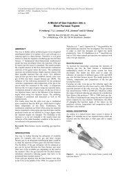
implies that our algorithm must recompute the Bézier coefficientsaccordingly. Our implementation is describedsequentially, although some steps do not require the previousstep to finish. A flowchart of the implementationcan be found in Figure 7.6.1 <strong>Silhouette</strong>ness calculation<strong>Silhouette</strong>ness is well suited for computation on the <strong>GPU</strong>since it is the same transform applied to every edge andsince there are no data dependencies. The only changingparameter between frames is the viewpoint.If the mesh is static we can pre-compute the edgemidpointsand neighboring triangle normals for everyedge as a preprocessing step and store these values in atexture on the <strong>GPU</strong>. For a dynamic mesh we store the indicesof the vertices of the two adjacent triangles insteadand calculate the midpoint as part of the silhouettenesscomputation.The silhouetteness of the edges is calculated by firstsending the current viewpoint to the <strong>GPU</strong> as a shader uniform,and then by issuing the rendering of a textured rectangleinto an off-screen buffer with the same size as ouredge-midpoint texture.We could alternatively store the edges and normals ofseveral meshes in one texture and calculate the silhouettenessof all in one pass. If the models have different modelspace bases, such as in a scene graph, we reserve a texelin a viewpoint-texture for each model. In the preprocessingstep, we additionally create a texture associating theedges with the model’s viewpoint texel. During renderingwe traverse the scene graph, find the viewpoint in themodel space of the model and store this in the viewpointtexture. We then upload this texture instead of setting theviewpoint explicitly.6.2 Histogram pyramid construction andextractionThe next step is to determine which triangles should berefined, based on the silhouetteness of the edges. Thestraightforward approach is to read back the silhouettenesstexture to host memory and run sequentially throughthe triangles to determine the refinement level for each ofthem. This direct approach rapidly congests the graphicsbus and thus reduces performance. To minimize transfersover the bus we use a technique called histogram pyramidextraction [23] to find and compact only the data thatwe need to extract for triangle refinement. As an addedbenefit the process is performed in parallel on the <strong>GPU</strong>.The first step in the histogram pyramid extraction is toselect the elements that we will extract. We first create abinary base texture with one texel per triangle in the mesh.A texel is set to 1 if the corresponding triangle is selectedfor extraction, i.e. has at least one edge with non-zerosilhouetteness, and 0 otherwise. We create a similar basetexture for the edges, setting a texel to 1 if the correspondingedge has at least one adjacent triangle that is selectedand 0 otherwise.For each of these textures we build a histopyramid,which is a stack of textures similar to a mipmap pyramid.The texture at one level is a quarter of the size of theprevious level. Instead of storing the average of the fourcorresponding texels in the layer below like for a mipmap,we store the sum of these texels. Thus each texel in thehistopyramid contains the number of selected elements inthe sub-pyramid below and the single top element containsthe total number of elements selected for extraction.Moreover, the histopyramid induces an ordering of the selectedelements that can be obtained by traversal of thepyramid. If the base texture is of size 2 n ×2 n , the histopyramidis built bottom up in n passes. Note that for a staticmesh we only need a histopyramid for edge extraction andcan thus skip the triangle histopyramid.The next step is to compact the selected elements. Wecreate a 2D texture with at least m texels where m is thenumber of selected elements and each texel equals its indexin a 1D ordering. A shader program is then used tofind for each texel i the corresponding element in the basetexture as follows. If i > m there is no corresponding selectedelement and the texel is discarded. Otherwise, thepyramid is traversed top-down <strong>using</strong> partial sums at theintermediate levels to determine the position of the i’thselected element in the base texture. Its position in thebase texture is then recorded in a pixel buffer object.The result of the histopyramid extraction is a compactrepresentation of the texture positions of the elements forwhich we need to extract data. The final step is to load associateddata into pixel buffer objects and read them backto host memory over the graphics bus. For static mesheswe output for each selected edge its index and silhouetteness.We can thus fit the data of two edges in the RGBADraftDraft7
values of one render target.For dynamic meshes we extract data for both the selectedtriangles and edges. The data for a triangle containsthe vertex positions and shading normals of the cornersof the triangle. Using polar coordinates for normalvectors, this fit into four RGBA render targets. The edgedata is the edge index, its silhouetteness and the two innerBézier control points of that edge, all of which fits intotwo RGBA render targets.6.3 Rendering unrefined trianglesWhile the histopyramid construction step finishes, we issuethe rendering of the unrefined geometry <strong>using</strong> a VBO(vertex buffer object). We encode the triangle index intothe geometry stream, for example as the w-coordinates ofthe vertices. In the vertex shader, we use the triangle indexto do a texture lookup in the triangle refinement texture inorder to check if the triangle is tagged for refinement. Ifso, we collapse the vertex to [0, 0, 0], such that trianglestagged for refinement are degenerate and hence produceno fragments. This is the same approach as [5] uses todiscard geometry.For static meshes, we pass the geometry directly fromthe VBO to vertex transform, where triangles tagged forrefinement are culled. For dynamic meshes, we replacethe geometry in the VBO with indices and retrieve the geometryfor the current frame <strong>using</strong> texture lookups, beforeculling and applying the vertex transforms.The net effect of this pass is the rendering of the coarsegeometry, with holes where triangles are tagged for refinement.Since this pass is vertex-shader only, it can becombined with any regular fragment shader for lightningand shading.6.4 Rendering refined trianglesWhile the unrefined triangles are rendered, we wait forthe triangle data read back to the host memory to finish.We can then issue the rendering of the refined triangles.The geometry of the refined triangles are tessellations oftriangular cubic Bézier patches as described in Section 4and 5.To allow for high frame-rates, the transfer of geometryto the <strong>GPU</strong>, as well as the evaluation of the surface,must be handled carefully. Transfer of vertex data overthe graphics bus is a major bottleneck when renderinggeometry. Boubekeur et.al. [3] have an efficient strategyfor rendering uniformly sampled patches. The ideais that the parameter positions and triangle strip set-up arethe same for any patch with the same topological refinementlevel. Thus, it is enough to store a small numberof pre-tessellated patches P i with parameter positions I ias VBOs on the <strong>GPU</strong>. The coefficients of each patch areuploaded and the vertex shader is used to evaluate the surfaceat the given parameter positions. We use a similarset-up, extended to our adaptive watertight tessellations.The algorithm is similar for static and dynamic meshes,the only difference is the place from which we read thecoefficients. For static meshes, the coefficients are pregeneratedand read directly from host memory. The coefficientsfor a dynamic mesh are obtained from the edgeand triangle read-back pixel pack buffers. Note that thispass is vertex-shader only and we can therefore use thesame fragment shader as for the rendering of the unrefinedtriangles.The tessellation strategy described in Section 5 requiresthe evaluation of (11) at the vertices of the tessellationP m of the parameter domain of F, i.e. at the dyadic parameterpoints (6) at refinement level m. Since the maximalrefinement level M over all patches is usually quitesmall, we can save computations by pre-evaluating the basisfunctions at these points and store these values in atexture.A texture lookup gives four channels of data, and sincea cubic Bézier patch has ten basis functions, we needthree texture lookups to get the values of all of them ata point. If we define the center control point b 111 to bethe average of six other control points, as in (5), we caneliminate it by distributing the associated basis functionB 111 = uvw/6 = µ/6 among the six corresponding basisfunctions,DraftDraftˆB 3 300 = u 3 , ˆB3 201 = 3wu 2 +µ, ˆB3 102 = 3uw 2 +µ,ˆB 3 030 = v 3 , ˆB3 120 = 3uv 2 +µ, ˆB3 210 = 3vu 2 +µ,ˆB 3 003 = w 3 , ˆB3 012 = 3vw 2 +µ, ˆB3 021 = 3wv 2 +µ.(12)We thus obtain a simplified expressionF = ∑ b ijk B ijk =∑(i,j,k)≠(1,1,1)b ijk ˆBijk (13)8
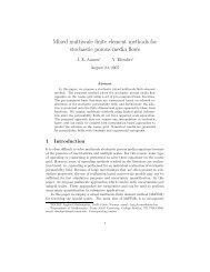
involving only nine basis functions. Since they form apartition of unity, we can obtain one of them from theremaining eight. Therefore, it suffices to store the valuesof eight basis functions, and we need only two texturelookups for evaluation per point. Note that if wechoose the center coefficient as in (4) we need three texturelookups for retrieving the basis functions, but the remainderof the shader is essentially the same.Due to the linearity of the sampling operator, we mayexpress (11) for a vertex p of P M with s(p) = m + α asv = S s(p) [F](p) = ∑ i,j,kb ijk S s(p) [ ˆB ijk ](p) (14)= ∑ i,j,kb ijk((1 − α)S m [ ˆB ijk ](p) + αS m+1 [ ˆB)ijk ](p)Thus, for every vertex p of P M , we pre-evaluateS m [ ˆB 3 300](p), . . . , S m [ ˆB 3 021](p) for every refinementlevel m = 1, . . . , M and store this in a M × 2 blockin the texture. We organize the texture such that four basisfunctions are located next to the four correspondingbasis functions of the adjacent refinement level. This layoutoptimizes spatial coherency of texture accesses sincetwo adjacent refinement levels are always accessed whena vertex is calculated. Also, if vertex shaders on futuregraphics hardware will support filtered texture lookups,we could increase performance by carrying out the linearinterpolation between refinement levels by sampling betweentexel centers.Since the values of our basis function are always in inthe interval [0, 1], we can trade precision for performanceand pack two basis functions into one channel of data,letting one basis function have the integer part while theother has the fractional part of a channel. This reduces theprecision to about 12 bits, but increases the speed of thealgorithm by 20% without adding visual artifacts.6.5 Normal and displacement mappingOur algorithm can be adjusted to accommodate most regularrendering techniques. Pure fragment level techniquescan be applied directly, but vertex-level techniques mayneed some adjustment.An example of a pure fragment-level technique is normalmapping. The idea is to store a dense sampling ofthe object’s normal field in a texture, and in the fragmentshader use the normal from this texture instead of the interpolatednormal for lighting calculations. The result of<strong>using</strong> normal mapping on a coarse mesh is depicted in theleft of Figure 8.Normal mapping only modulates the lighting calculations,it does not alter the geometry. Thus, silhouettes arestill piecewise linear. In addition, the flat geometry is distinctivelyvisible at gracing angles, which is the case forthe sea surface in Figure 8.The displacement mapping technique attacks this problemby perturbing the vertices of a mesh. The drawbackis that displacement mapping requires the geometry in. problem areas to be densely tessellated. The brute forcestrategy of tessellating the whole mesh increase the complexitysignificantly and is best suited for off-line rendering.However, a ray-tracing like approach <strong>using</strong> <strong>GPU</strong>s hasbeen demonstrated by Donnelly [6].We can use our strategy to establish the problem areasof the current frame and use our variable-level of detail refinementstrategy to tessellate these areas. First, we augmentthe silhouetteness test, tagging edges that are largein the current projection and part of planar regions at gracingangles for refinement. Then we incorporate displacementmapping in the vertex shader of Section 6.4. However,care must be taken to avoid cracks and maintain awatertight surface.DraftDraftFor a point p at integer refinement level s, we find thetriangle T = [p i , p j , p k ] of P s that contains p. We thenfind the displacement vectors at p i , p j , and p k . The displacementvector at p i is found by first doing a texturelookup in the displacement map <strong>using</strong> the texture coordinatesat p i and then multiplying this displacement withthe interpolated shading normal at p i . In the same fashionwe find the displacement vectors at p j and p k . Thethree displacement vectors are then combined <strong>using</strong> thebarycentric weights of p with respect to T , resulting ina displacement vector at p. If s is not an integer, we interpolatethe displacement vectors of two adjacent levelssimilarly to (9).The result of this approach is depicted to the right inFigure 8, where the cliff ridges are appropriately jaggedand the water surface is displaced according to the waves.9
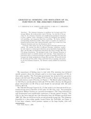
Figure 8: The left image depicts a coarse mesh <strong>using</strong> normal mapping to increase the perceived detail, and the rightimage depicts the same scene <strong>using</strong> the displacement mapping technique described in Section 6.5.<strong>Silhouette</strong> extractions pr. sec100k10k1k1007800 GT6600 GTBruteHierarchal10100 1k 10k 100kNumber of triangles(a) The measured performance for brute force CPU silhouetteextraction, hierarchical CPU silhouette extraction,and the <strong>GPU</strong> silhouette extraction on the Nvidia GeForce6600GT and 7800GT <strong>GPU</strong>s.Frames pr. sec10kDraftDraft1k1002410Static meshUniformStatic VBODynamicmesh1100 1k 10k 100kNumber of triangles(b) The measured performance on an Nvidia GeForce7800GT for rendering refined meshes <strong>using</strong> one single staticVBO, the uniform refinement method of [3], and our algorithmfor static and dynamic meshes.Figure 9: Performance measurements of our algorithm.10
the added complexity balances out the performance of thetwo approaches to some extent.We have tested against two methods of uniform refinement.The first method is to render the entire refinedmesh as a static VBO stored in graphics memory. Therendering of such a mesh is fast, as there is no transferof geometry across the graphics bus. However, the meshis static and the VBO consumes a significant amount ofgraphics memory. The second approach is the method ofBoubekeur and Schlick [3], where each triangle triggersthe rendering of a pre-tessellated patch stored as trianglestrips in a static VBO in graphics memory.Figure 9(b) shows these two methods against our adaptivemethod. It is clear from the graph that <strong>using</strong> staticVBOs is extremely fast and outperforms the other methodsfor meshes up to 20k triangles. At around 80k triangles,the VBO grows too big for graphics memory, andis stored in host memory, with a dramatic drop in performance.The method of [3] has a linear performancedegradation, but the added cost of triggering the renderingof many small VBOs is outperformed by our adaptivemethod at around 1k triangles. The performance of ourmethod also degrades linearly, but at a slower rate thanuniform refinement. Using our method, we are at 24 FPSable to <strong>adaptively</strong> refine meshes up to 60k for dynamicmeshes, and 100k triangles for static meshes, which is significantlybetter than the other methods. The other <strong>GPU</strong>sshow the same performance profile as the 7800 in Figure9(b), just shifted downward as expected by the number ofpipelines and lower clock speed.Finally, to get an idea of the performance impact of variousparts of our algorithm, we ran the same tests withvarious features enabled or disabled. We found that <strong>using</strong>uniformly distributed random refinement level for eachedge (to avoid the silhouetteness test), the performanceis 30–50% faster than uniform refinement. This is as expectedsince the vertex shader is only marginally morecomplex, and the total number of vertices processed is reduced.In a real world scenario, where there is often a highdegree of frame coherency, this can be utilized by not calculatingthe silhouetteness for every frame. Further, if wedisable blending of consecutive refinement levels (whichcan lead to some popping, but no cracking), we removehalf of the texture lookups in the vertex shader for refinedgeometry and gain a 10% performance increase.8 Conclusion and future workWe have proposed a technique for performing adaptiverefinement of triangle meshes <strong>using</strong> graphics hardware,requiring just a small amount of preprocessing, and withno changes to the way the underlying geometry is stored.Our criterion for adaptive refinement is based on improvingthe visual appearance of the silhouettes of the mesh.However, our method is general in the sense that it caneasily be adapted to other refinement criteria, as shown inSection 6.5.We execute the silhouetteness computations on a <strong>GPU</strong>.Our performance analysis shows that our implementation<strong>using</strong> histogram pyramid extraction outperforms other silhouetteextraction algorithms as the mesh size increases.Our technique for adaptive level of detail automaticallyavoids cracking between adjacent patches with arbitraryrefinement levels. Thus, there is no need to “grow” refinementlevels from patch to patch, making sure two adjacentpatches differ only by one level of detail. Ourrendering technique is applicable to dynamic and staticmeshes and creates continuous level of detail for both uniformand adaptive refinement algorithms. It is transparentfor fragment-level techniques such as texturing, advancedlighting calculations, and normal mapping, and the techniquecan be augmented with vertex-level techniques suchas displacement mapping.Our performance analysis shows that our techniquegives interactive frame-rates for meshes with up to 100kDraftDrafttriangles. We believe this makes the method attractivesince it allows complex scenes with a high number ofcoarse meshes to be rendered with smooth silhouettes.The analysis also indicates that the performance of thetechnique is limited by the bandwidth between host andgraphics memory. Since the CPU is available for othercomputations while waiting for results from the <strong>GPU</strong>, thetechnique is particularly suited for CPU-bound applications.This also shows that if one could somehow eliminatethe read-back of silhouetteness and trigger the refinementdirectly on the graphics hardware, the performanceis likely to increase significantly. To our knowledgethere are no such methods <strong>using</strong> current versions ofthe OpenGL and Direct3D APIs. However, consideringthe recent evolution of both APIs, we expect such functionalityin the near future.A major contribution of this work is an extension of12
the technique described in [3]. We address three issues:evaluation of PN-triangle type patches on vertex shaders,adaptive level of detail refinement and elimination of poppingartifacts. We have proposed a simplified PN-triangletype patch which allows the use of pre-evaluated basisfunctionsrequiring only one single texture lookup (if wepack the pre-evaluated basis functions into the fractionaland rational parts of a texel). Further, the use of a geometricrefinement level different from the topological refinementlevel comes at no cost since this is achieved simplyby adjusting a texture coordinate. Thus, adaptive level ofdetail comes at a very low price.We have shown that our method is efficient and we expectit to be even faster when texture lookups in the vertexshader become more mainstream and the hardware manufacturersanswer with increased efficiency for this operation.Future <strong>GPU</strong>s use a unified shader approach, whichcould also boost the performance of our algorithm since itis primarily vertex bound and current <strong>GPU</strong>s perform thebest for fragment processing.AcknowledgmentsWe would like to thank Gernot Ziegler for introducing usto the histogram pyramid algorithm. Furthermore, we aregrateful to Mark Hartner for giving us access to the sourcecode of the various silhouette extraction algorithms. Finally,Marie Rognes has provided many helpful commentsafter reading an early draft of this manuscript. This workwas funded, in part, by contract number 158911/I30 ofThe Research Council of Norway.References[1] P. Alliez, N. Laurent, and H. S. F. Schmitt. Efficientview-dependent refinement of 3D meshes <strong>using</strong>√ 3-subdivision. The Visual Computer, 19:205–221, 2003.ICS conf. on Graphics hardware, pages 99–104,2005.[4] M. Bunnell. <strong>GPU</strong> Gems 2, chapter 7 Adaptive Tessellationof Subdivision Surfaces with DisplacementMapping. Addison-Wesley Professional, 2005.[5] D. Card and J. L.Mitchell. ShaderX, chapterNon-Photorealistic Rendering with Pixel and VertexShaders. Wordware, 2002.[6] W. Donnelly. <strong>GPU</strong> Gems 2, chapter 8 Per-Pixel DisplacementMapping with Distance Functions. AddisonWesley Professional, 2005.[7] C. Dyken and M. Reimers. <strong>Real</strong>-time linear silhouetteenhancement. In Mathematical Methods forCurves and Surfaces: Tromsø 2004, pages 135–144.Nashboro Press, 2004.[8] G. Farin. Curves and surfaces for CAGD. MorganKaufmann Publishers Inc., 2002.[9] M. Harris. <strong>GPU</strong> Gems 2, chapter 31 Mapping ComputationalConcepts to <strong>GPU</strong>s. Addison Wesley Professional,2005.[10] A. Hartner, M. Hartner, E. Cohen, and B. Gooch.Object space silhouette algorithims. In Theoryand Practice of Non-Photorealistic Graphics: Algorithms,Methods, and Production System SIG-GRAPH 2003 Course Notes, 2003.DraftDraft[11] H. Hoppe. Progressive meshes. In ACM SIGGRAPH1996, pages 99–108, 1996.[12] T. Isenberg, B. Freudenberg, N. Halper,S. Schlechtweg, and T. Strothotte. A developer’sguide to silhouette algorithms for polygonal models.IEEE Computer Graphics and Applications,23(4):28–37, July-Aug 2003.[2] T. Boubekeur, P. Reuter, and C. Schlick. Scalartagged PN triangles. In Eurographics 2005 (ShortPapers), 2005.[3] T. Boubekeur and C. Schlick. Generic mesh refinementon <strong>GPU</strong>. In ACM SIGGRAPH/EUROGRAPH-√[13] L. Kobbelt. 3-subdivision. In ACM SIGGRAPH2000, pages 103–112, 2000.[14] D. Luebke, B. Watson, J. D. Cohen, M. Reddy, andA. Varshney. Level of Detail for 3D Graphics. ElsevierScience Inc., 2002.13
[15] J. D. Owens, D. Luebke, N. Govindaraju, M. Harris,J. Krüger, A. E. Lefohn, and T. J. Purcell. Asurvey of general-purpose computation on graphicshardware. In Eurographics 2005, State of the ArtReports, pages 21–51, Aug. 2005.[16] K. Pulli and M. Segal. Fast rendering of subdivisionsurfaces. In ACM SIGGRAPH 1996 Visual Proceedings:The art and interdisciplinary programs, 1996.[17] R. J. Rost. OpenGL(R) Shading Language. AddisonWesley Longman Publishing Co., Inc., 2006.[18] P. V. Sander, X. Gu, S. J. Gortler, H. Hoppe, andJ. Snyder. <strong>Silhouette</strong> clipping. In SIGGRAPH 2000,pages 327–334, 2000.[19] L.-J. Shiue, I. Jones, and J. Peters. A realtime<strong>GPU</strong> subdivision kernel. ACM Trans. Graph.,24(3):1010–1015, 2005.[20] D. Shreiner, M. Woo, J. Neider, and T. Davis.OpenGL(R) Programming Guide. Addison WesleyLongman Publishing Co., Inc., 2006.[21] K. van Overveld and B. Wyvill. An algorithm forpolygon subdivision based on vertex normals. InComputer Graphics International, 1997. Proceedings,pages 3–12, 1997.[22] A. Vlachos, J. Peters, C. Boyd, and J. L. Mitchell.Curved PN triangles. In ACM Symposium on Interactive3D 2001 graphics, 2001.[23] G. Ziegler, A. Tevs, C. Tehobalt, and H.-P. Seidel.Gpu point list generation through histogram pyramids.Technical Report MPI-I-2006-4-002, Max-Planck-Institut für Informatik, 2006.DraftDraft14