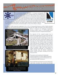
University of Missouri, Rolla - Network for Earthquake Engineering ...
University of Missouri, Rolla - Network for Earthquake Engineering ...
University of Missouri, Rolla - Network for Earthquake Engineering ...
- No tags were found...

Create successful ePaper yourself
Turn your PDF publications into a flip-book with our unique Google optimized e-Paper software.
Participants<strong>University</strong> <strong>of</strong> Nevada, RenoDavid Sanders (Project PI)• <strong>University</strong> <strong>of</strong> <strong>Missouri</strong>, <strong>Rolla</strong>• Abdeldjelil “DJ” Belarbi (co-PI)• Pedro Silva• Ashraf Ayoub• <strong>University</strong> <strong>of</strong> Illinois-Champaign-Urbana• Amr Elnashai (co-PI)• Reginald DesRoches (GaTech(GaTech)• <strong>University</strong> <strong>of</strong> Cali<strong>for</strong>nia,Los Angeles• Jian Zhang (co-PI)• Washington <strong>University</strong>, St.Louis• Shirley Dyke (co-PI)• <strong>University</strong> <strong>of</strong> Mexico• Sergio Alcocer
Causes <strong>of</strong> Combined ActionsSystem to Component to System• Functional Constraints - curved or skewedbridges• Geometric Considerations - uneven spans ordifferent column heights• Multi-directional <strong>Earthquake</strong> Motions -significant vertical motions input or nearfield fling impacts• Structural Constraints - stiff deck, movementjoints, soil condition and foundations
Significance <strong>of</strong> Vertical Motion• Effects <strong>of</strong> Vertical Motions on Structures• Direct Compressive Failure• Reduction <strong>of</strong> Shear and Moment Capacity• Increase in Shear and Moment Demand• Axial Force Responseaxial <strong>for</strong>ce: kN310029002700250023002100190017001500Santa Monica Freeway, Pier 6TransverseTrans + LongTrans + Vert8 8.5 9 9.5 10 10.5 11time: seconds
Significance <strong>of</strong> Torsion• Interaction <strong>of</strong> Shear-Torsion results in early coverspalling <strong>of</strong> non-circular/rectangular cross-sectionsdue to circulatory shear stresses.• What are the effects <strong>of</strong> warping on the flexural andshear capacity <strong>of</strong> columns?• What is the impact <strong>of</strong> multiple loadings on thintubetheory?• What are the effects on the curvature ductility andlocation <strong>of</strong> the plastic hinge?
M-V-T InteractionsBending-ShearShear-TorsionCombination <strong>of</strong>Bending-Shear-Torsion
Parameters• Cross-section - Circle, Interlocking Spiral, Square• Column aspect ratio - moment/shear ratio• Torsion/shear ratio - high and low torsion• Level <strong>of</strong> axial loads• Level <strong>of</strong> detailing <strong>for</strong> high and moderateseismicity• Bidirectional bending moment -non-circularcross-sections• Type <strong>of</strong> Loading – Slow Cyclic, Pseudo-dynamicand shake table/dynamic
Pre-test System Analysis• Per<strong>for</strong>m seismic simulations <strong>of</strong> bridge systemsunder combined actions to study effects <strong>of</strong> variousbridge components on global and local seismicresponse behavior <strong>of</strong> bridge system• Bridge superstructure• Columns (Piers)• Foundations and surrounding soil• Embankments• Nonlinear soil-foundationfoundation-structure interaction• Multi-directional motions
Analysis• Selected 4 ground motion suites that incorporate thesite-dependent probabilistic hazard analysis and groundmotion disaggregation analysis.• Selected 2 bridge prototypes that are distinctive interms <strong>of</strong> structural characteristics and dynamicproperties.• Conducted time history analysis <strong>of</strong> prototype bridgessubjected to multi-directional ground shakings andevaluate the effect <strong>of</strong> vertical motions on seismicdemand.• Implemented nonlinear structural and foundationelements.
StructuralCharacteristicsSpan/SpanLengthPier TypeAbutment TypeFoundationExpansionJointsForce ResistingMechanismExamples <strong>of</strong> Prototype BridgesDesign Example #4 Design Example #8Three-span continuous,320 ft longTwo-column integral bent,pinned at baseSeatSpread FootingExpansion Bearings &Shear KeysLongitudinal: intermediatebents & free movement atabutmentsTransverse: intermediatebent columns &abutmentsFive-span continuous,500 ft longTwo-column integral bent,monolithic at top and baseStub abutment/diaphragmPileExpansion BearingsLongitudinal: intermediatebents and abutment backfillTransverse: intermediatebent columns and abutmentbackfill
axial <strong>for</strong>ce(kip)Structural Response <strong>of</strong> Bridge #85.0E+02time(s)0.0E+00-5.0E+020.0 5.0 10.0 15.0 20.0shear <strong>for</strong>ce_x(kip)shear <strong>for</strong>ce_z(kip)1.0E+03-1.0E+03-1.5E+03-2.0E+03-2.5E+031.5E+021.0E+025.0E+010.0E+000.0-5.0E+015.0 10.0 15.0 20.0-1.0E+02time(s)-1.5E+028.0E+026.0E+024.0E+022.0E+02-4.0E+02-6.0E+02-8.0E+02Force DemandBottom <strong>of</strong> Column inBent#3Top <strong>of</strong> Column in Bent#10.0E+00-2.0E+020.0 5.0 10.0 15.0 20.0time(s)Bottom <strong>of</strong> Column in Bent#1relative disp._z(ft)axial relative disp.(ft)relative disp._x(ft)1.0E-015.0E-020.0E+000.0 5.0 10.0 15.0 20.0-5.0E-02-1.0E-018.0E-016.0E-014.0E-012.0E-01-4.0E-01-6.0E-015.0E-03-5.0E-03-1.0E-02-1.5E-02Displacement Demand0.0E+000.0 5.0 10.0 15.0 20.0Column in Bent#3Column in Bent#1time(s)0.0E+00-2.0E-010.0 5.0 10.0 15.0 20.0Column in Bent#1time(s)Tensiontime(s)1986 N. Palm Springs <strong>Earthquake</strong>
Pre-test Component Analysis• Per<strong>for</strong>m pretest simulations <strong>of</strong> test specimenswith realistic loading and boundary conditions• Provide guidance <strong>for</strong> tests conducted• Optimize number and parameters <strong>of</strong> test specimens• Identify realistic loading and boundary conditions• Integrate various analytical models into theframework <strong>of</strong> UI-Simcor<strong>for</strong> pseudo-dynamic dynamic hybridtesting
Analytical Program• Development Inelastic Models <strong>for</strong> RC Sectionsunder Combined Loading• Modeling <strong>of</strong> Specimens tested under Pseudo-Dynamic/Dynamic Conditions• Complex and Simplified Tools• Parametric Studies• Bridge System Analysis• Development <strong>of</strong> Seismic Design Criteria
Development Inelastic Models <strong>for</strong> RCSections under Combined LoadingDeficiencies <strong>of</strong> Available Analytical Models:• Current Inelastic Frame s<strong>of</strong>tware Packages(e.g. OpenSees, , Zeus-NL,FedeasLab) ) focuson flexural behavior <strong>of</strong> RC members only.• The combined axial/shear/flexural/torsionalbehavior is not considered in current models.
Experimental Program• Experimental investigation <strong>of</strong> columns under multi-directional loadings with varying levels <strong>of</strong> axial <strong>for</strong>ceand axial-flexure interaction ratios linked to analysis.• Slow cyclic tests at UMR.• Pseudo-dynamic dynamic tests at UIUC• Dynamic tests at UNR• Integrated bridge test managed by UMR, tested atUIUC
UMR Test SetupStrong W all Load CellHydralic JackLoad StubHydraulic ActuatorsSteel Strands(Inside C olum n)Test UnitSupport BlocksStrong Floor
Test SetupStrong WallStrong WallLoading FrameHydraulic ActuatorsLoad StubTest Unit
UMR Test SetupPosition <strong>of</strong> (2) Horizontal Actuators.Actuators Position <strong>for</strong> S-PatternloadingTest Unit (InterlockingSpiral Column Setup <strong>for</strong> Bi-AxialBending Shown)ψθLoading FrameRotation Angle –Twist/TorsionTest Unit Offset Angle<strong>for</strong> Bi-Axial BendingLoadingFrame
Shape Ht. Scale Design Directions DescriptionM01 -24 108 1:2 High U, A1Level 1axial-high shearflexure(I01)(a)M02 -24 108 1:2 High U, T, A1 M01 with torsion (e)M05 -24 108 1:2 High U, T, A1 M02 with high torsion (c)M06 -24 150 1:2 High U, T, A1 high torsion (d)M07 -24 150 1:2 Mod. U, A1 M01 with moderate details (b)M08 -24 150 1:2 High T, A2 Level 2 axial-torsion (g)M09 -24 150 1:2 High U, T, A2 Level 2 Axial (f)M10 -24x48 150 1:2 High U (m) Level 1 axial-low shear- (b)M11 -24x48 150 1:2 High U (M) M10 with bidirectional M (b)M12 - 24x48 150 1:2 High U, T (m) M10 with torsion (d)M13 - 24x48 150 1:2 High U, T (M) M11 with torsion (d)M14 - 24x24 108 1:2 High U Level 1 axial-high shear (a)M15- 24x24108 1:2 Mod. U, TM14 with high torsion andM16M17- 24x24-24-24-24156 1:2 Mod. U, T144156108UMR Test Matrix1:21:21:2HighHighHigh<strong>Earthquake</strong>Testing in Junemoderate details (c)M15 with high torsion andmoderate details (d)Prototype bridge evaluation –DONE AT UIUC by UMR.
Column Fabrication
Column TestingSpecimen M07:Ductility 8
Large Testing Facility, UIUC
Large Testing Facility, UIUC• Three 6 DOF loading and boundarycondition boxes <strong>of</strong> capacity 3000kNto 4500kN• Displacement capacity +/- 250 mmper box• Reaction wall ~15x9x8 meters• Three advanced high speed DACsystems• Video and J-Camera Jdata capture• Simulation Coordinator UI-SIMCOR<strong>for</strong> multi-site hybrid simulationDisp.Forc.UI-SimCorForc.Disp.ExperimentModuleStatic AnalysisModule
Small Scale Testing Facility, UIUC
UIUC Experiment• MISST test (previous multi-site test at UIUC) will provide the test bed<strong>for</strong> the loading protocols• Tests <strong>of</strong> 3 large scale and 4 small scale bridge columns with differentferentaspect ratios and seismic design details using MUST-SIM SIM Facility• Column test with UMR under different loading conditions‣ Verify local and global analytical part <strong>of</strong> the hybrid simulation‣ Provide an opportunity <strong>for</strong> researchers outside <strong>of</strong> a NEES facility‣ Detailed design <strong>of</strong> UIUC and UNR experiments will be guided by bridgesystem analysisTest at UIUCSmall Scale Test Large Scale Test Test with UMRNEES-R
• Current testingSmall-Scale Scale Testing• Several 1/16 scaled piers are currently being tested• Used to evaluate system and material/pier designTest SetupAfter Test
UNR Shake Table Facility•Previous Tests haveFocused on UnidirectionalMotion.•System <strong>of</strong> Decoupling theVertical Load and InertialMass has been used.•Vertical Load wasHeld Constant.A system will now be used to decouple variableaxial load from the inertial load with bi-directional lateral shaking.
UNR ProgramShape Ht. Scale Design Directions Description104CA,E1,E2 Constant axial, low1:3 High,T shear, torsion104VA,E1,E2 N01 but with variable1:3 High,T axial load72CA,E1,E2 Constant axial, high1:3 High,T shear, torsion72VA,E1,E2 N03 but with variable1:3 High,T axial load72Variable axial, high- 12x20 1:4 High VA,E1,E2shear- 12x20 72VA,E1,E21:4 HighN05 with torsion,T- 12x20 72VA,E3,E4 N06 with near field1:4 High,T motions72VA,E1,E2- 12x20 1:4 HighN07 with high torsion,T2N01 - 16N02 - 16N03 - 16N04 - 16N05N06N07N08
UMR Test at UIUCUI-SIMCORTested StructureDisp.Structural ModuleForce(Zeus-NL)ForceDisp.Soil & FoundationModule(OpenSees)
International Cooperation• <strong>University</strong> <strong>of</strong> MexicoShape Ht. Scale Design Directions DescriptionX01 - 20 x 20 80 1:1.2 High CA, U Strengthened priorto testingX02 - 20 x 20 80 1:1.2 High CA, U X01 with secondrepair schemeX03 - 20x80 120 1:2 High CA, U1 BidirectionalMotion 1X04 - 20x80 120 1:2 High CA, U2 BidirectionalMotion 2
Educational Activities• UCIST shake tablesincorporated <strong>for</strong>hands-on exercisesand experiments• Existing K-12 Koutreach programs will beenhanced with additional modules• UNR: Summer camps and ME2L program• UIUC: <strong>Engineering</strong> Open House• UMR: High school engineering summer course• WU: GK-12 Program
Educational Activities• Modules to be developed to enhance curriculum onundergraduate and graduate levels• Undergraduates involved in research through REUprograms• Encourage students from underrepresented groupsthrough Minority <strong>Engineering</strong> Program, GAMES,MERGE, and GetSet program• Online continuing education course to be developed atUMR <strong>for</strong> practicing Engineers
UMR as NEES-POPUMR
UMR as NEES-POP
UMR as NEES-POP
Questions??