Using CFD modeling to improve combustion in rotary kilns ... - Fives
Using CFD modeling to improve combustion in rotary kilns ... - Fives
Using CFD modeling to improve combustion in rotary kilns ... - Fives

Create successful ePaper yourself
Turn your PDF publications into a flip-book with our unique Google optimized e-Paper software.
<strong>Us<strong>in</strong>g</strong> <strong>CFD</strong> <strong>model<strong>in</strong>g</strong><strong>to</strong> <strong>improve</strong> <strong>combustion</strong> <strong>in</strong> <strong>rotary</strong> <strong>kilns</strong> and precalc<strong>in</strong>ersDr Patrick MUSCAT, Doc<strong>to</strong>r-Eng. of Marseilles University, dipl. eng<strong>in</strong>eer of ENSAE (Sup Aéro)Manager of <strong>CFD</strong> Department, <strong>Fives</strong> Pillard, Marseille (France)PLANTS CONCERNED AND TYPES OF <strong>CFD</strong> SOFTWARE USEDThe <strong>kilns</strong> studied are: <strong>rotary</strong> <strong>kilns</strong> for the production of grey and white cement, <strong>rotary</strong> <strong>kilns</strong> for lime, nickel.The cement precalc<strong>in</strong>ers studied are suspension preheater type, cyclone type.The <strong>CFD</strong> software used is FLUENT® of ANSYS. Two types of <strong>CFD</strong> simulations are carried out: Cold <strong>CFD</strong> simulations (flow patterns): They allow <strong>to</strong> <strong>improve</strong> the <strong>combustion</strong> air flow pattern <strong>to</strong> the burners <strong>in</strong> order <strong>to</strong>smooth the <strong>combustion</strong> and render the flame more symmetrical. Inside the <strong>rotary</strong> kiln, it appears also possible <strong>to</strong> simulatethe <strong>in</strong>troduction of hot secondary air <strong>in</strong><strong>to</strong> the flame, which <strong>in</strong>fluences the flame temperature and radiation on<strong>to</strong> thecalc<strong>in</strong>ated bed. <strong>CFD</strong> simulations <strong>in</strong> <strong>combustion</strong>: They allow <strong>to</strong> compare the <strong>in</strong>fluence of different burner designs on flame shape onthe radiation received by the material bed <strong>to</strong> be calc<strong>in</strong>ated, <strong>to</strong> understand the <strong>in</strong>fluence of several <strong>in</strong>let parametersconcern<strong>in</strong>g either the fuel used, or the kiln geometrical dimensions, the position of the burner <strong>in</strong> the kiln, the variousvelocities.S<strong>in</strong>ce the studies are essentially comparative, the necessity <strong>to</strong> master absolute values is not essential. However, it is possible<strong>to</strong> tune the model by tak<strong>in</strong>g an example of a kiln <strong>in</strong> operation (for which we dispose of kiln shell scanner record<strong>in</strong>gs as well asall the geometrical dimensions and <strong>in</strong>let data parameters), and adapt the model so that it gives a similar temperature profileon the kiln shell <strong>to</strong> the one measured, thus ensur<strong>in</strong>g that the simulated flame pattern is comparable <strong>to</strong> the experimentalone.EXAMPLE OF IMPROVEMENTS ACHIEVED THANKS TO THE USE OF <strong>CFD</strong>Rotary <strong>kilns</strong> for white cementThe user <strong>in</strong>tended <strong>to</strong> reduce NOx emissions with a new burner, but wanted <strong>to</strong> be sure that with the new burner the radiationreceived by cl<strong>in</strong>ker bed would beat least ma<strong>in</strong>ta<strong>in</strong>ed or, if possible, <strong>improve</strong>d. First of all the simulations showed that the<strong>in</strong>fluence of <strong>combustion</strong> air distribution was very large and it was absolutely necessary <strong>to</strong> be <strong>improve</strong>d. The result of thesimulations shows that with the new generation of <strong>Fives</strong> Pillard burner and an optimisation of the <strong>combustion</strong> air flowdistribution, the radiation received by the cl<strong>in</strong>ker bed was <strong>improve</strong>d.The success at the commission<strong>in</strong>g site confirms the <strong>CFD</strong> conclusions and the validity of the <strong>CFD</strong> model used.Temperature profile (old burner)Temperature profile (new burner)1/9
Radiation received by cl<strong>in</strong>ker bedRotary kiln for nickelIn the plant concerned, a problem of flame shape and stability was encountered. <strong>CFD</strong> <strong>model<strong>in</strong>g</strong> was used <strong>to</strong> understand,then correct the problem:Geometrical model with details of the kiln hoodThe analysis showed that a bad <strong>combustion</strong> air velocity distribution <strong>in</strong> the kiln hood was probably the cause of the problem:Visualisation of flow <strong>in</strong> the kiln hood2/9
Several simulations have been carried out <strong>to</strong> def<strong>in</strong>e the shape of devices necessary <strong>to</strong> optimize air flow:Detail of the mechanical element of the flow correction deviceWe can see that once the air distribution has been deeply modified <strong>in</strong> the kiln hood, then the problem of the uncontrolledflame air root disappeared and the temperature profile <strong>improve</strong>s:Before optimisationAfter optimisationTemperature profiles before and after optimisationThe commission<strong>in</strong>g results confirmed very good kiln operation.3/9
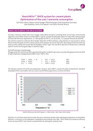
Studies on cement precalc<strong>in</strong>era) SNCR system on a ris<strong>in</strong>g duct downstream a <strong>rotary</strong> kilnThe <strong>CFD</strong> is an essential <strong>to</strong>ol for the eng<strong>in</strong>eer<strong>in</strong>g phase of a SNCR (NOx reduction) system applied <strong>to</strong> exist<strong>in</strong>g plants.Such an eng<strong>in</strong>eer<strong>in</strong>g process can be broken down as follows:First, further <strong>to</strong> site temperature measurements, we determ<strong>in</strong>e the appropriate reaction zone. Then, we use <strong>CFD</strong> forcalculat<strong>in</strong>g the flue gas balance and simulate velocities and temperature profiles <strong>in</strong> the reaction zone:Temperature and velocity profiles at kiln outlet (<strong>Fives</strong> Pillard Neutr<strong>in</strong>ox® SNCR system)The second phase consists <strong>in</strong> modell<strong>in</strong>g the droplets of (urea/water) or (ammonia/water) solution, and their vaporiz<strong>in</strong>g<strong>in</strong> the flue gas stream. The number of <strong>in</strong>jec<strong>to</strong>rs, their location po<strong>in</strong>t and their droplet velocities may be optimized:First level: ma<strong>in</strong> <strong>in</strong>jection (Neutr<strong>in</strong>ox®)Second level: optimization (Neutr<strong>in</strong>ox®)First and second level <strong>in</strong>jec<strong>to</strong>rs (Neutr<strong>in</strong>ox®)The target consists <strong>in</strong> cover<strong>in</strong>g the entire cross section of the flue gas duct with the <strong>in</strong>jected urea / ammonia spray.4/9
Profiles of Mass fraction of NH 3(Neutr<strong>in</strong>ox®)Higher profilesDepend<strong>in</strong>g on the <strong>CFD</strong> modell<strong>in</strong>g conclusions, the urea (or ammonia) / water solution is <strong>in</strong>jected through 6-10 a<strong>to</strong>miz<strong>in</strong>gguns <strong>in</strong>stalled on 1, 2, or 3 levels <strong>in</strong> the calc<strong>in</strong>er. Usually two levels are sufficient. The first level aims at cover<strong>in</strong>g the maximumsurface with the longest resident time, while the second level aims at optimiz<strong>in</strong>g the reaction and efficiency.The <strong>in</strong>jec<strong>to</strong>rs optimization <strong>in</strong>cludes the choice of emulsion velocity (an a<strong>to</strong>miz<strong>in</strong>g fluid is used, <strong>in</strong> general compressed air),the choice of orifices, number and angle. The special a<strong>to</strong>mizer is patented (n° FR 0605355 of 06/15/2006).b) Another example of SNCR system on suspension preheaters application concerns a cement plant located <strong>in</strong> Vietnam:Hon Chong Cement VietnamDue <strong>to</strong> the high capacity of the cement l<strong>in</strong>e (5,000 tpd), it has been <strong>in</strong>stalled on two levels with six <strong>in</strong>jec<strong>to</strong>rs each.Another example <strong>in</strong> Italy shows that data collected dur<strong>in</strong>g the first commission<strong>in</strong>g period obliged us <strong>to</strong> reconsider thehypothesis taken at the project stage, thus modify<strong>in</strong>g the position of the <strong>in</strong>jec<strong>to</strong>rs. They were moved downwards <strong>in</strong> thecalc<strong>in</strong>er chamber:Precalc<strong>in</strong>er (Italy): <strong>CFD</strong> model and location of urea <strong>in</strong>jection levels5/9
The first <strong>in</strong>jection level position corresponded <strong>to</strong> a <strong>to</strong>o low residence time which was <strong>in</strong>duc<strong>in</strong>g low SNCR efficiency.The <strong>CFD</strong> helped <strong>to</strong> redef<strong>in</strong>e the new <strong>in</strong>jection level position with higher residence time lead<strong>in</strong>g <strong>to</strong> an <strong>in</strong>crease of ureaconsumption efficiency: The analysis of flue gas flow shape <strong>in</strong> the precalc<strong>in</strong>a<strong>to</strong>r showed that -as a matter of fact- a bigrecirculation zone was <strong>in</strong>creas<strong>in</strong>g the mix<strong>in</strong>g time <strong>in</strong> a convenient temperature w<strong>in</strong>dow:Temperature profileVelocity profileVisualisation of urea mix<strong>in</strong>gWith such a modification, an <strong>in</strong>crease of about 10% of deNOx reaction efficiency was reached, correspond<strong>in</strong>g <strong>to</strong> a 10% ureaconsumption sav<strong>in</strong>g.c) Studies on precalc<strong>in</strong>er burnersA comparative study of the effect of primary air used on precalc<strong>in</strong>er burners has been carried out, and allowed us <strong>to</strong> concludethat the primary air <strong>in</strong>duces a reduc<strong>in</strong>g <strong>combustion</strong> zone around the burners which has an big effect on the temperatureprofile:Effect of precalc<strong>in</strong>er burner primary air on temperature profileFurther studies on precalc<strong>in</strong>ers are pend<strong>in</strong>g; they aim at look<strong>in</strong>g deeper <strong>in</strong><strong>to</strong> the position of burner air <strong>in</strong>lets and <strong>to</strong> try <strong>to</strong>understand whether the precalc<strong>in</strong>er’s operation can be <strong>improve</strong>d <strong>in</strong> the future by simple modifications.6/9
Rotary cement <strong>kilns</strong>: comparison of flame shapes<strong>CFD</strong> simulations can be used <strong>in</strong>tensively <strong>to</strong> analyse flow patternsaround the burner. Cold <strong>CFD</strong> simulations allow <strong>to</strong> visualize andcompare flow patterns.A first example concerns the comparison of secondary air flow shapeas a function of the burner tip position <strong>in</strong>side the kiln. It confirmsthe site results i.e. the penetration of secondary air <strong>in</strong>side the flamedepends on the burner tip position:Secondary air flow shapesas a function of burner position <strong>in</strong>side the kilnThis study (also) allows <strong>to</strong> prove that there is no recirculation zone around the burner flame: it is clear that no recirculationeddy can exist around the flame:Secondary air flow shapeAnother example concerns the effect of swirl with 2 different burner configurations (s<strong>in</strong>gle annular outlet or double outlet).The comparison of the velocity profile at the burner outlet clearly shows that the double air outlet is better than a s<strong>in</strong>gle airoutlet s<strong>in</strong>ce the flame stays under control and there no risk of flame open<strong>in</strong>g (wide flame) lead<strong>in</strong>g <strong>to</strong> kiln shell overheat<strong>in</strong>gas well as sulphur volatilization.S<strong>in</strong>gle air outlet burner: effect of <strong>in</strong>creas<strong>in</strong>g swirlDouble outlet burner: effect of <strong>in</strong>creas<strong>in</strong>g swirl7/9
The <strong>CFD</strong> modell<strong>in</strong>g allows also <strong>to</strong> analyze the loss of velocities at the burner outlet. The simulations have been carried outwith the same air fan pressure (250 mbar). It clearly appears that with a s<strong>in</strong>gle primary air outlet there is a loss of velocity:The useful velocities at burner outlet are about 100 m/s, due <strong>to</strong> the enlargement of the burner cross section, while itrema<strong>in</strong>s at about 250 m/s when a separated second “slot-designed”:yellow is # 250 m/sgreen is # 100 m/sVelocities at s<strong>in</strong>gle air outlet burnerVelocities at double air outlet burnerCold modell<strong>in</strong>g of different burner configurations (axial primary air tip) show that <strong>in</strong> <strong>in</strong>creas<strong>in</strong>g the burner “slot effect”promotes hot secondary air suction <strong>in</strong><strong>to</strong> the flame, thus <strong>in</strong>tensify<strong>in</strong>g the flame:AXIAL TIP WITHOUT “SLOTS”fully openclosedAXIAL TIP WITH “SLOTS”fully openclosedVisualisation of the “slot” effect on air flow patterns (velocities)Visualisation of secondary air <strong>in</strong>troduction <strong>in</strong><strong>to</strong> the flame(the colour represents the temperature of the mix)8/9
In order <strong>to</strong> confirm the above described “cold modell<strong>in</strong>g”, a complete modell<strong>in</strong>g <strong>in</strong> <strong>combustion</strong> has been achieved.The geometric size of the kiln is represented below:Rotary kiln modelOnly the first 50 m from the burner have been modelled due <strong>to</strong> computational considerations. The kiln rotation is taken <strong>in</strong><strong>to</strong>account. The details of the burner geometry have been taken <strong>in</strong><strong>to</strong> account. The fuel is coal. The secondary air temperaturehas been chosen at 800°C. The cl<strong>in</strong>ker has been modelled as a solid entity <strong>in</strong> motion, and the heat exchange has beenmodelled. The simulations concern<strong>in</strong>g the <strong>combustion</strong> of coal particles <strong>in</strong>clude various axial primary air <strong>in</strong>jections for thesame burner, thus several different “SLOT EFFECTS” for same operational conditions.The conclusion appears as follows:Radiation on cl<strong>in</strong>ker bed with different burner axial air <strong>in</strong>jectionsCONCLUSIONThe belief that <strong>CFD</strong> modell<strong>in</strong>g cannot br<strong>in</strong>g a real progress <strong>in</strong> <strong>combustion</strong> for <strong>rotary</strong> <strong>kilns</strong> or cement precalc<strong>in</strong>ers nowappears completely obsolete.It is clear that comparisons based on different “<strong>in</strong>let” [<strong>combustion</strong>/kiln fuel] parameters give precise data and allow <strong>to</strong>choose which configuration can <strong>improve</strong> a real situation.The site results obta<strong>in</strong>ed allowed <strong>to</strong> confirm that the provisions were sufficiently reliable. Simulations with liquid fluidflows do not hold any real <strong>in</strong>terest s<strong>in</strong>ce <strong>CFD</strong> modell<strong>in</strong>g is now an efficient <strong>to</strong>ol and the time available for modell<strong>in</strong>g workis decreas<strong>in</strong>g rapidly.Such a <strong>to</strong>ol allows <strong>to</strong> design a <strong>combustion</strong> system associated with a real kiln which, as a matter of fact, may allow <strong>to</strong>simplify adjustments at site. Even more <strong>in</strong>terest<strong>in</strong>g is the fact that such a design can be “tuned” <strong>to</strong> the priority targets ofthe user, which may differ from one kiln <strong>to</strong> another (for example : “cl<strong>in</strong>ker reactivity”, “high LSF raw material”, “limited NOxemission”, “high percentage of alternative solid fuels”, “use high ash low volatile coal”, etc...).Such <strong>CFD</strong> studies are now a common way of work<strong>in</strong>g, and br<strong>in</strong>g feedback from experience every day. This is why we hopethat , thanks <strong>to</strong> such new <strong>to</strong>ol, real progress on the calc<strong>in</strong>ed product quality or on the polluants emission (NOx, CO, andCO 2….) will be more easily achievable.9/9