Stainless Steel High Vacuum Angle/In-line Valve - SMC Pneumatics
Stainless Steel High Vacuum Angle/In-line Valve - SMC Pneumatics
Stainless Steel High Vacuum Angle/In-line Valve - SMC Pneumatics
- No tags were found...

You also want an ePaper? Increase the reach of your titles
YUMPU automatically turns print PDFs into web optimized ePapers that Google loves.
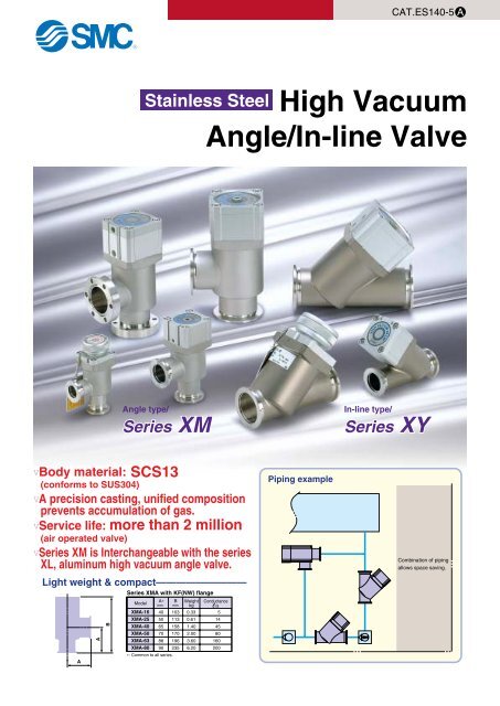
CAT.ES140-5 A<strong>Stainless</strong> <strong>Steel</strong> <strong>High</strong> <strong>Vacuum</strong><strong>Angle</strong>/<strong>In</strong>-<strong>line</strong> <strong>Valve</strong><strong>Angle</strong> type/Series XM<strong>In</strong>-<strong>line</strong> type/Series XYVBody material: SCS13(conforms to SUS304)VA precision casting, unified compositionprevents accumulation of gas.VService life: more than 2 million(air operated valve)VSeries XM is <strong>In</strong>terchangeable with the seriesXL, aluminum high vacuum angle valve.Light weight & compact—————————AABSeries XMA with KF(NW) flangeModelXMA-16XMA-25XMA-40XMA-50A∗mm4050657088Bmm103113158170XMA-63 196XMA-80 90 235∗: Common to all series.Weightkg0.330.611.402.003.606.20Conductancel/s5144580160200Piping exampleCombination of pipingallows space saving.
Series VariationsApplicationShaft sealsystemModels<strong>Angle</strong> type <strong>In</strong>-<strong>line</strong> type<strong>Valve</strong>typeOperatingpressurePa 16Flange size25 40 50 63 80Options'<strong>High</strong> temp.Switch <strong>In</strong>dicator specificationAir operatedXMAXYASingleacting(N.C.)Note)Particulate freeBellows sealXMCXYCDoubleactingAtmosphericpressureto 1 x 10 -6Note)XMDXYDReducesparticulatesEliminatespump over loadsBellows,O-ring sealSingleacting(N.C.)StandardPAT.PAT.ManualXMHXYHParticulate freeBellows sealAtmosphericManualpressureto 1 x 10 -6Note)StandardStandardNote) The in-<strong>line</strong> valve is not available in flange size 16.Bellows seal, Single acting: XMA, XYABellows seal, Double acting: XMC, XYC• Bellows type is particulate free and completely cleaned.• Pressure balance mechanism allows unrestricted exhaust direction.2 stage control, Single acting: XMD, XYD• <strong>In</strong>itial exhaust valve and main exhaust valve have been integrated(2 stage flow control valve).• Unrestrected exhaust direction.• Makes compact system design and reduced piping possible.• Minimizes particulates by eliminating turbulence during exhaust.• Prevents pump overload.• <strong>In</strong>itial exhaust valve flow is adjustable and adjustment can be locked.Bellows seal, Manual operation: XMH, XYH• Bellows type is particulate free and completely cleaned.• Pressure balance mechanism allows unrestricted exhaust direction.• Low actuation torque (0.5N·m or less).• Spring provides standard sealing load.• Handle height is the same when valve is open or closed.• <strong>In</strong>dicator to confirm opening and closing of valve is standard equipment.Features 1
<strong>Stainless</strong> steel<strong>High</strong> <strong>Vacuum</strong> <strong>Angle</strong>/<strong>In</strong>-<strong>line</strong> <strong>Valve</strong>Series XMA, XYANormally Closed/Bellows SealHow to Order<strong>Angle</strong> type<strong>In</strong>-<strong>line</strong> typeXMAXYA16 M9N A25 M9N A1 2 3 4 5 671. Flange sizeSize162540506380XMAVVVVVV3. <strong>In</strong>dicator/Pilot port directionXMASymbol <strong>In</strong>dicator Pilot port directionNilAWithout indicator Flange sideFlange sideFLeft flange surfaceWith indicatorGRear flange surfaceJKLMRight flange surfaceLeft flange surfaceWithout indicator Rear flange surfaceRight flange surface4. Temperature specificationsSymbolTemperature rangeNil5 to 60°CH05 to 150°CXYA—VVVVV6. No. of auto switches/Detecting positionSymbolNilABCQuantityWithout auto switch2 pcs.1 pc.1 pc.Detecting position—<strong>Valve</strong> open/closed<strong>Valve</strong> open<strong>Valve</strong> closed7. Seal material and its changed part· Seal materialSymbolNilN1P1Q1R1R2R3S1T1U1Seal materialFKMEPDMBARRELPERFLUORO ®Kalrez ®CHEMRAZ ®VMQFKM for PlasmaULTICARMOR ®∗: Produced by Mitsubishi Cable <strong>In</strong>dustries, Ltd.Left flange surfaceRear flange surfaceFlange sideCompound No.1349-80 ∗2101-80 ∗70W4079SS592SS630SSE381232-70 ∗3310-75 ∗UA4640Right flange surface2. Flange typeXMASymbolNilDCXYANilDTypeKF (NW)K (DN)CFXYASymbol <strong>In</strong>dicator Pilot port directionNilAFWithout indicator Rear flange sideRear flange sideWith indicator Left flange surfaceJRight flange surfaceKLeft flange surfaceWithout indicatorMRight flange surface5. Auto switch typeSymbol Auto switchNil—M9N (L) D-M9N (L)M9P (L) D-M9P (L)M9B (L) D-M9B (L)A90 (L) D-A90 (L)A93 (L) D-A93 (L)M9//—Applicable flange size16, 25, 40, 50, 63, 8063, 8016 (034), 40 (070), 63 (114)KF (NW) 25, 40, 50, 63, 80K (DN)63, 80RemarksWithout auto switch (without built-in magnet)Solid state switchReed switch(Flange size 16 is not available.)Without auto switch (with built-in magnet)· Part numbers indicating changed seal material and leakageSymbolChangedLeakage Pa m 3 /s or less Note 1)part Note 2)<strong>In</strong>ternalExternalNilABC—2, 3231.3 x 10 -10 (FKM)1.3 x 10 -81.3 x 10 -81.3 x 10 -10 (FKM)1.3 x 10 -11 (FKM)1.3 x 10 -91.3 x 10 -11 (FKM)1.3 x 10 -9Note 1) Values at ambient temperatures, excluding gas permeation.Note 2) Refer to parts number of “Construction” on the page 2 for changed part.Number indicates parts number of “Construction” accordingly.Left flange surfaceRear flange surfaceFlange sideAuto switches cannot be mounted in the case of high temperature types (temperature specifications H0).The standard lead wire length is 0.5m. For 3m, “L” is added at the end of the part number.Ex.) -M9NLTo order something else “Nil” (standard), list the symbols starting with “X”,followed by each symbol for “seal material” and then “changed parts” at last.Ex.) XMA-16-M9NA-XN1ARight flange surface1
Series XMA, XYASpecificationsModelFlange (valve) size<strong>Valve</strong> typeFluidOperating temperature °COperating pressure PaConductance l/s Note 1)Leakage Pa·m 3 /sOperating time s<strong>In</strong>ternalExternalXMA-16XMA-25XYA-25XMA-40XYA-40XMA-50XYA-50XMA-63XYA-63XMA-80XYA-8016, CF034 25 40, CF070 50 63, CF114 8050.05Normally closed (Pressurize to open, spring seal)<strong>In</strong>active gas under vacuum5 to 60 (<strong>High</strong> temperature type: 5 to 150)Atmospheric pressure to 1 x 10 -614 45 80 160 2001.3 x 10 -10 {1 x 10 -10 } at ambient temperature, excluding gas permeation1.3 x 10 -11 {1 x 10 -11 } at ambient temperature, excluding gas permeation0.1 0.21 0.24 0.26 0.28Flange typeKF (NW), CF KF (NW) KF (NW), CF KF (NW)KF (NW),K (DN), CFKF (NW),K (DN)Principle materialsPilot pressure MPaPilot port sizeService life (million cycles)Weight kg Note 2)∗XMAXYANote 1) Conductance is the value for the molecular flow of an elbow having the same dimensions.Note 2) Figures in ( ) indicates the weight of CF, conflate fittings.Body: SCS13 (Conforms to <strong>Stainless</strong> steel SUS304) Bellows: <strong>Stainless</strong> steel SUS316L Bellows holder: <strong>Stainless</strong> steel SUS304. FKM (Standard seal material)0.4 to 0.7M5 Rc 1/8200 (FKM seal material)0.33(0.37) 0.61 1.40(1.76) 2.00 3.60(4.96)—0.661.422.404.306.207.70ConstructionXMA/<strong>Angle</strong> typeXYA/<strong>In</strong>-<strong>line</strong> typeAuto switch (Optional)1. Bonnet assembly (Maintenance part) ∗ (<strong>In</strong>cludes 2, 5, 6, 7)Magnet (Optional)Pilot port7. Bellows holder (Material: <strong>Stainless</strong> steel SUS304)3. Exterior seal (Maintenance part) ∗6. Bellows (Material: <strong>Stainless</strong> steel SUS316L)5. <strong>Valve</strong> (Material: <strong>Stainless</strong> steel SUS304)2. <strong>Valve</strong> seal (Maintenance part) ∗4. Body (Material: SCS13)Refer to the page 22 for the maintenance parts.2
3Series XMA, XYA<strong>Stainless</strong> steel<strong>High</strong> <strong>Vacuum</strong> <strong>Angle</strong>/<strong>In</strong>-<strong>line</strong> <strong>Valve</strong>DimensionsXMA/<strong>Angle</strong> typeXYA/<strong>In</strong>-<strong>line</strong> type100.2130178209268XYA-25XYA-40XYA-50XYA-63XYA-80ModelA79.5106119149178B486679100117C12233D23.538536180E40557587114Fn———95110Fd2641527083G648495118142H(mm)405065708890XMA-16XMA-25XMA-40XMA-50XMA-63XMA-80ModelA103113158170196235B38486679100117C112233D3040557587114Fn————95110Fd34—70—114—Fc172641527083G403963686996HP.C.D 27—P.C.D 58.7—P.C.D 92.1—P.C.D L16-ø4.4—6-ø6.6—8-ø8.4—L2(mm)ABAHøGCCDøGøFnEAB45°HøFnCCD(KF flange)øL2øFdøFc(K flange) (CF flange)L1(øFc)øFd(K flange)(KF flange)
<strong>Stainless</strong> steel<strong>High</strong> <strong>Vacuum</strong> <strong>Angle</strong>/<strong>In</strong>-<strong>line</strong> <strong>Valve</strong>Series XMC, XYCDouble Acting/Bellows SealHow to Order<strong>Angle</strong> type<strong>In</strong>-<strong>line</strong> typeXMCXYC1625M9N AM9N A1 2 3 4 5 671. Flange sizeSize162540506380XMCVVVVVV3. Pilot port directionXMCSymbol Pilot port directionNilFlange sideK Left flange surfaceL Rear flange surfaceM Right flange surfaceLeft flange surfaceXYC—VVVVVRear flange surfaceRight flange surface2. Flange typeXMCSymbolNilDCXYCNilDXYCSymbolNilKMTypeKF (NW)K (DN)CFPilot port directionRear flange surfaceLeft flange surfaceRight flange surfaceApplicable flange size16, 25, 40, 50, 63, 8063, 8016 (034), 40 (070), 63 (114)KF (NW) 25, 40, 50, 63, 80K (DN)63, 80Left flange surfaceRear flange surfaceRight flange surface4. Temperature specificationsSymbolTemperature rangeNil5 to 60°CH05 to 150°C6. No. of auto switches/Detecting positionSymbolNilABCQuantityWithout auto switch2 pcs.1 pc.1 pc.Detecting position—<strong>Valve</strong> open/closed<strong>Valve</strong> open<strong>Valve</strong> closed7. Seal material and its changed part· Seal materialSymbolNilN14P1Q1R1R2R3S1T1U1Seal materialFKMEPDMBARRELPERFLUORO ®Kalrez ®CHEMRAZ ®VMQFKM for PlasmaULTICARMOR ®∗: Produced by Mitsubishi Cable <strong>In</strong>dustries, Ltd.Flange sideCompound No.1349-80 ∗2101-80 ∗70W4079SS592SS630SSE381232-70 ∗3310-75 ∗UA46405. Auto switch typeSymbol Auto switchNil—M9N (L) D-M9N (L)M9P (L) D-M9P (L)M9B (L) D-M9B (L)A90 (L) D-A90 (L)A93 (L) D-A93 (L)M9//—Flange sideRemarksWithout auto switch (without built-in magnet)Solid state switchReed switch(Flange size 16 is not available.)Without auto switch (with built-in magnet)Auto switches cannot be mounted in the case of high temperature types (temperature specifications H0).The standard lead wire length is 0.5m. For 3m, “L” is added at the end of the part number.Ex.) -M9NL· Part numbers indicating changed seal material and leakageSymbolChangedLeakage Pa m 3 /s or less Note 1)part Note 2)<strong>In</strong>ternalExternalNilABC—2, 3231.3 x 10 -10 (FKM)1.3 x 10 -81.3 x 10 -81.3 x 10 -10 (FKM)1.3 x 10 -11 (FKM)1.3 x 10 -91.3 x 10 -11 (FKM)1.3 x 10 -9Note 1) Values at ambient temperatures, excluding gas permeation.Note 2) Refer to parts number of “Construction” on the page 5 for changed part.Number indicates parts number of “Construction” accordingly.To order something else “Nil” (standard), list the symbols starting with “X”,followed by each symbol for “seal material” and then “changed parts” at last.Ex.) XMC-16-M9NA-XN1A
<strong>Stainless</strong> steel<strong>High</strong> <strong>Vacuum</strong> <strong>Angle</strong>/<strong>In</strong>-<strong>line</strong> <strong>Valve</strong>Series XMC, XYCSpecificationsModelFlange (valve) size<strong>Valve</strong> typeFluidOperating temperature °COperating pressure PaConductance l/s Note 1)Leakage Pa·m 3 /sOperating time s<strong>In</strong>ternalExternalXMC-16XMC-25XYC-25XMC-40XYC-40XMC-50XYC-50XMC-63XYC-63XMC-80XYC-8016, CF034 25 40, CF070 50 63, CF114 8050.08Double acting (Dual operation), pressurize to open/close<strong>In</strong>active gas under vacuum5 to 60 (<strong>High</strong> temperature type: 5 to 150)Atmospheric pressure to 1 x 10 -614 45 80 160 2001.3 x 10 -10 {1 x 10 -10 } at ambient temperatures, excluding gas permeation1.3 x 10 -11 {1 x 10 -11 } at ambient temperatures, excluding gas permeation0.15 0.35 0.4 0.54 0.7Flange typeKF (NW), CF KF (NW) KF (NW), CF KF (NW)KF (NW),K (DN), CFKF (NW),K (DN)Principle materialsPilot pressure MPaPilot port sizeService life (million cycles)Weight kg Note 2)XMCXYC0.36 (0.40)—Note 1) Conductance is the value for the molecular flow of an elbow having the same dimensions.Note 2) Figures in ( ) indicates the weight of CF, conflate fittings.Body: SCS13 (Conforms to <strong>Stainless</strong> steel SUS304) Bellows: <strong>Stainless</strong> steel SUS316L Bellows holder: <strong>Stainless</strong> steel SUS304. FKM (Standard seal material)0.3 to 0.6M5 Rc 1/8200 (FKM seal material)0.620.671.40 (1.76)1.422.102.503.80 (5.16)4.506.307.80ConstructionXMC/<strong>Angle</strong> typeXYC/<strong>In</strong>-<strong>line</strong> typeAuto switch (Optional)Pilot port (Pressurized to close)1. Bonnet assembly (Maintenance part) ∗ (<strong>In</strong>cludes 2, 5, 6, 7)Magnet (Optional)Pilot port (Pressurized to open)7. Bellows holder (Material: <strong>Stainless</strong> steelSUS304)3. Exterior seal (Maintenance part) ∗6. Bellows (Material: <strong>Stainless</strong> steel SUS316L)5. <strong>Valve</strong> (Material: <strong>Stainless</strong> steel SUS304)2. <strong>Valve</strong> seal (Maintenance part) ∗4. Body (Material: SCS13)∗ Refer to the page 22 for the maintenance parts.5
6DimensionsXMC/<strong>Angle</strong> typeXYC/<strong>In</strong>-<strong>line</strong> type405065708890XMC-16XMC-25XMC-40XMC-50XMC-63XMC-80ModelA110120171183209250B38486679100117C112233D3040557587114Fn————95110Fd34—70—114—Fc172641527083G403963686996HJ262836384556P.C.D 27—P.C.D 58.7—P.C.D 92.1—P.C.D L16-ø4.4—6-ø6.6—8-ø8.4—L2(mm)100.2130178209268XYC-25XYC-40XYC-50XYC-63XYC-80ModelA85115129158189B486679100117C12233D23.538536180E40557587114Fn———95110Fd2641527083G6484951181422836384556HJ(mm)Series XMC, XYCAABøGJHøFnCCDøFnEA45°BJCCDøGHøL2øFdøFc(K flange) (CF flange)L1(øFc)øFd(K flange)(KF flange)(KF flange)
<strong>Stainless</strong> steel<strong>High</strong> <strong>Vacuum</strong> <strong>Angle</strong>/<strong>In</strong>-<strong>line</strong> <strong>Valve</strong>Series XMD, XYD2 Stage Control, Single Acting/Bellows, O-ring SealPAT.How to Order<strong>Angle</strong> type<strong>In</strong>-<strong>line</strong> typeXMDXYD2525M9N AM9N A1 2 3 4 5 671. Flange sizeSize2540506380XMDVVVVV3. Pilot port directionXMDSymbol Pilot port directionNilFlange sideK Left flange surfaceL Rear flange surfaceM Right flange surfaceLeft flange surfaceXYDVVVVVRear flange surfaceRight flange surface2. Flange typeXMDSymbolNilDCXYDNilDXYDSymbolNilKMTypeKF (NW)K (DN)CFKF (NW)K (DN)Pilot port directionRear flange surfaceLeft flange surfaceRight flange surfaceApplicable flange size25, 40, 50, 63, 8063, 8040 (070), 63 (114)25, 40, 50, 63, 8063, 80Left flange surfaceRear flange surfaceRight flange surfaceFlange side4. Temperature specificationsSymbolTemperature rangeNil5 to 60°CH05 to 150°C6. No. of auto switches/Detecting positionSymbolNilABCQuantityWithout auto switch2 pcs.1 pc.1 pc.Detecting position—<strong>Valve</strong> open/closed<strong>Valve</strong> open<strong>Valve</strong> closed7. Seal material and its changed part· Seal materialSymbolNilN1P1Q1R1R2R3S1T1U1Seal materialFKMEPDMBARRELPERFLUORO ®Kalrez ®CHEMRAZ ®VMQFKM for PlasmaULTICARMOR ®Compound No.1349-80 ∗2101-80 ∗70W4079SS592SS630SSE381232-70 ∗3310-75 ∗UA4640The material used in the sliding part of the S-valve is: FKM ∗: Produced by Mitsubishi Cable <strong>In</strong>dustries, Ltd.5. Auto switch typeSymbol Auto switchNil—M9N (L) D-M9N (L)M9P (L) D-M9P (L)M9B (L) D-M9B (L)A90 (L) D-A90 (L)A93 (L) D-A93 (L)M9//—Flange sideRemarksWithout auto switch (without built-in magnet)Solid state switchReed switch(Flange size 16 is not available.)Without auto switch (with built-in magnet)Auto switches cannot be mounted in the case of high temperature types (temperature specifications H0).The standard lead wire length is 0.5m. For 3m, “L” is added at the end of the part number.Ex.) -M9NL· Part numbers indicating changed seal material and leakageSymbolChangedLeakage Pa m 3 /s or less Note 1)part Note 2)<strong>In</strong>ternalExternalNilABC—2, 3, 4, 52, 4, 531.3 x 10 -10 (FKM)1.3 x 10 -81.3 x 10 -81.3 x 10 -10 (FKM)1.3 x 10 -11 (FKM)1.3 x 10 -91.3 x 10 -11 (FKM)1.3 x 10 -9Note 1) Values at ambient temperatures, excluding gas permeation.Note 2) Refer to parts number of “Construction” on the page 9 for changed part.Number indicates parts number of “Construction” accordingly.To order something else “Nil” (standard), list the symbols starting with “X”,followed by each symbol for “seal material” and then “changed parts” at last.Ex.) XMD-25-M9NA-XN1A7
Series XMD, XYDSpecificationsModelFlange (valve) size<strong>Valve</strong> typeFluidOperating temperature °COperating pressure PaMain exhaust valveConductance l/s Note 1)<strong>In</strong>itial exhaust valve<strong>In</strong>ternalLeakage Pa·m 3 /sExternalMain exhaust valveOperating time s<strong>In</strong>itial exhaust valveXMD-25XYD-2525Normally closed (Pressurize to open, spring seal) [both main & initial exhaust valves]<strong>In</strong>active gas under vacuum5 to 60 (<strong>High</strong> temperature type: 5 to 150)Atmospheric pressure to 1 x 10 -61445801602000.5 to 3 2 to 8 2.5 to 11 4 to 18 4 to 180.100.07XMD-40XYD-4040, CF0701.3 x 10 -10 {1 x 10 -10 } at ambient temperatures, excluding gas permeation1.3 x 10 -11 {1 x 10 -11 } at ambient temperatures, excluding gas permeation0.210.08XMD-50XYD-50500.240.09XMD-63XYD-6363, CF1140.260.23XMD-80XYD-80800.280.27Flange typeKF (NW)KF (NW), CFKF (NW)KF (NW),K (DN), CFKF (NW),K (DN)Principle materialsPilot pressure MPaPilot port sizeService life (million cycles)Weight kg Note 2)XMDXYDBody: SCS13 (Conforms to <strong>Stainless</strong> steel SUS304) Bellows: <strong>Stainless</strong> steel SUS316L Bellows holder: <strong>Stainless</strong> steel SUS304. FKM (Standard seal material)M5 Rc 1/8200 (FKM seal material)0.650.710.4 to 0.7 [both main and initial exhaust valves]1.50 (1.86)1.52Note 1) Main exhaust valve conductance is the value for the molecular flow of an elbow having the same dimensions. The initial exhaust valve is the value for the viscous flow.Note 2) Figures in ( ) indicates the weight of CF, conflate fittings.2.202.604.10 (5.46)4.806.808.308
<strong>Stainless</strong> steel<strong>High</strong> <strong>Vacuum</strong> <strong>Angle</strong>/<strong>In</strong>-<strong>line</strong> <strong>Valve</strong>Series XMD, XYDConstructionXMD/<strong>Angle</strong> typeAdjustment nut<strong>In</strong>itial exhaust valve opening adjustmentMagnet (Optional)Bellows holder 10(Material: <strong>Stainless</strong> steel SUS304)Bellows 9(Material: <strong>Stainless</strong> steel SUS316L)Auto switch (Optional)1 Bonnet assembly (Maintenance part) ∗(<strong>In</strong>cludes 2, 5, 7, 8, 9, 10)Pilot port S (For initial exhaust)Pilot port M (For main exhaust)3 Exterior seal (Maintenance part) ∗O-ring for sliding <strong>Valve</strong> S(Material: FKM)O-ring to fix 5<strong>Valve</strong> M 7(Material: <strong>Stainless</strong> steel SUS304)Body 6(Material: <strong>Stainless</strong> steel SCS13)<strong>Valve</strong> S 8(Material: <strong>Stainless</strong> steel SUS304)2 <strong>Valve</strong> seal (Maintenance part) ∗4 <strong>Valve</strong> S seal assembly (Maintenance part) ∗(Material: <strong>Stainless</strong> steel SUS304 + Seal material)XYD/<strong>In</strong>-<strong>line</strong> typeAuto switch (Optional)Bonnet assembly (Maintenance part) ∗ 1(<strong>In</strong>cludes 2, 5, 7, 8, 9, 10)Pilot port S (For initial exhaust)Pilot port M (For main exhaust)Adjustment nut (With knurl)<strong>In</strong>itial exhaust valve opening adjustmentMagnet (Optional)10 Bellows holder (Material: <strong>Stainless</strong> steel SUS304)9 Bellows (Material: <strong>Stainless</strong> steel SUS316L)Exterior seal (Maintenance part) ∗ 3O-ring to move valve S(Material: FKM)<strong>Valve</strong> seal (Maintenance part) ∗ 2<strong>Valve</strong> S seal assembly (Maintenance part) ∗ 4(Material: SUS304 + seal material)5 O-ring to fix7 <strong>Valve</strong> M(Material: <strong>Stainless</strong> steel SUS304)6 Body(Material: <strong>Stainless</strong> steel SCS13)8 <strong>Valve</strong> S(Material: <strong>Stainless</strong> steel SUS304)∗ Refer to the page 22 for maintenance parts. Series XMD, XYD[1] <strong>In</strong>itial exhaust valve opening adjustmentThe initial exhaust rate should be adjusted before operation (withpilot port S in an unpressurized state).The initial exhaust rate is set to zero by turning the adjustment nutclockwise until it just stops. (Do not use a tool.)The initial exhaust rate is adjusted by turning the nut anti-clockwise. Thenumber of adjustment nut (its pitch is 1mm) rotations and initial exhaustconductance should be confirmed referring to the figure on the right.[2] Opening of the initial exhaust valve (valve S)When pressure is applied to the pilot port S, the valve S is removedfrom the valve S assembly and opens until the adjusted opening setting.[3] Opening of the main exhaust valve (valve M)When pressure is applied to the pilot port M, the valve M isremoved from the body seat surface and fully opens.[4] Closing of the initial exhaust valve, the main exhaust valveBy removing the pressure from the pilot ports S and M, both valvesreturn to their sealed position.<strong>In</strong>itial exhaust valve conductance l/s (viscous flow)Shows flow rate when P=0.1MPa2018161412108642XMD/XYD-63XMD/XYD-80XMD/XYD-25XMD/XYD-50XMD/XYD-4000.0 0.5 1.0 1.5 2.0 2.5 3.0 3.4 4.0 4.5 5.0 5.5 6.0Adjustment nut rotations n9
10DimensionsXMD/<strong>Angle</strong> typeXYD/<strong>In</strong>-<strong>line</strong> type5065708890XMD-25XMD-40XMD-50XMD-63XMD-80ModelA123170183217256B486679100117C12233D40557587114Fn———95110Fd—70—114—Fc2641527083G4163687298H J K16202020207.51517.519.526.5—P.C.D 58.7—P.C.D 92.1—P.C.D L1—6-ø6.6—8-ø8.4—L2(mm)100.2130178209268XYD-25XYD-40XYD-50XYD-63XYD-80ModelA86.7114128163193B486679100117C12233D23.538536180E40557587114Fn———95110Fd2641527083G6684951211441620202020HJ7.51517.519.526.5K(mm)Series XMD, XYDøL2øFdøFc(K flange) (CF flange)L1(øFc)øFd(K flange)(KF flange)(KF flange)MSAAB KCCøFnøGJHDMSøFnEA45°BCCDøGJ KH
<strong>Stainless</strong> steel<strong>High</strong> <strong>Vacuum</strong> <strong>Angle</strong>/<strong>In</strong>-<strong>line</strong> <strong>Valve</strong>Series XMH, XYHManual <strong>Valve</strong>/Bellows SealHow to Order<strong>Angle</strong> type<strong>In</strong>-<strong>line</strong> typeXMHXYH16251 2 31. Flange sizeSize16254050XMHVVVVXYH—VVV2. Flange typeXMHSymbolNilCTypeKF (NW)CFApplicable flange size16, 25, 40, 5016 (034), 40 (070)XYHNil KF (NW) 25, 40, 503. Seal material and its changed part· Seal materialSymbolNilN1P1Q1R1R2R3S1T1U1Seal materialFKMEPDMBARRELPERFLUORO ®Kalrez ®CHEMRAZ ®VMQFKM for PlasmaULTICARMOR ®∗: Produced by Mitsubishi Cable <strong>In</strong>dustries, Ltd.Compound No.1349-80 ∗2101-80 ∗70W4079SS592SS630SSE381232-70 ∗3310-75 ∗UA4640· Part numbers indicating changed seal material and leakageSymbolChangedLeakage Pa m 3 /s or less Note 1)part Note 2)<strong>In</strong>ternalExternalNilABC—2, 3231.3 x 10 -10 (FKM)1.3 x 10 -81.3 x 10 -81.3 x 10 -10 (FKM)1.3 x 10 -11 (FKM)1.3 x 10 -91.3 x 10 -11 (FKM)1.3 x 10 -9Note 1) Values at ambient temperatures, excluding gas permeation.Note 2) Refer to parts number of “Construction” on the page 12 for changed part.Number indicates parts number of “Construction” accordingly.To order something else “Nil” (standard), list the symbols starting with “X”,followed by each symbol for “seal material” and then “changed parts” at last.Ex.) XMH-16-XN1A11
Series XMH, XYHSpecificationsFlange (valve) size<strong>Valve</strong> typeFluidOperating temperature °COperating pressure PaConductance l/s Note 1)Leakage Pa·m 3 /sFlange typePrinciple materialsPilot torque N·mHandle revolutionsService life (million cycles)Weight kg Note 2)∗Model<strong>In</strong>ternalExternalXMHXYHXMH-1616, CF034Note 1) Conductance is the value for the molecular flow of an elbow having the same dimensions.Note 2) Figures in ( ) indicates the weight of CF, conflate fittings.5KF (NW), CF0.1 %50.31 (0.35)—XMH-25XYH-2525Manual type<strong>In</strong>active gas under vacuum5 to 150Atmospheric pressure to 1 x 10 -6141.3 x 10 -10 {1 x 10 -10 } at ambient temperature, excluding gas permeation1.3 x 10 -11 {1 x 10 -11 } at ambient temperature, excluding gas permeationKF (NW)Body: SCS13 (Conforms to <strong>Stainless</strong> steel SUS304) Bellows: <strong>Stainless</strong> steel SUS316L Bellows holder: <strong>Stainless</strong> steel SUS304. FKM (Standard seal material)0.15 %70.570.6210XMH-40XYH-4040, CF07045KF (NW), CF0.35 %101.35 (1.71)1.37XMH-50XYH-505080KF (NW)0.5 %132.022.42ConstructionXMH/<strong>Angle</strong> typeXYH/<strong>In</strong>-<strong>line</strong> type<strong>In</strong>dicator1. Handle assembly (Maintenance part) ∗ (<strong>In</strong>cludes 2, 5, 6, 7)7. Bellows holder (Material: <strong>Stainless</strong> steel SUS304)3. Exterior seal (Maintenance part) ∗6. Bellows (Material: <strong>Stainless</strong> steel SUS316L)5. <strong>Valve</strong> (Material: <strong>Stainless</strong> steel SUS304)2. <strong>Valve</strong> seal (Maintenance part) ∗4. Body (Material: SCS13)Refer to the page 22 for the maintenance parts.12
<strong>Stainless</strong> steel<strong>High</strong> <strong>Vacuum</strong> <strong>Angle</strong>/<strong>In</strong>-<strong>line</strong> <strong>Valve</strong>Series XMH, XYHDimensionsXMH/<strong>Angle</strong> typeCDøL2øHABJCøFnøGAModelXMH-16XMH-25XMH-40XMH-50A40506570B100.5114162.5179.5C38486679D1122Fn30405575Fc34—70—G17264152H3540.55770J1821.53035P.C.D L1P.C.D 27—P.C.D 58.7—(mm)L26-ø4.4—6-ø6.6—XYH/<strong>In</strong>-<strong>line</strong> typeDCCøGBJ(KF flange)øFcL1(øFc)(CF flange)øHA(KF flange)øFnEModelXYH-25XYH-40XYH-50A100.2130178B75.8102.5119C486679D122E23.53853Fn405575G264152H40.55770(mm)J21.5303513
Technical Data1 Seal Materials Available4 Molecular flow conductanceFKM (fluoro rubber)With low outgassing, low permanent-set and low gaspermeation rate, this is the most popular seal material for highvacuum. <strong>SMC</strong>’s seal material has undergone a high vacuumdegassing process.Kalrez ®This is an elastomer with the most outstanding resistance toheat and chemicals, but its permanent-set is large, andspecial caution is required when used in other than staticapplications. Variations are available with improved plasma(O2, CF4) and particulate resistance. Therefore, it is advisableto select types based upon the application.Chemraz ®This material has excellent chemical and plasma resistanceand has slightly higher heat resistance than FKM. Severalvariations of Chemraz ® are available and it is advisable tomake a selection based upon the particular plasma beingused and other conditions, etc.∗ Chemraz ® is a registered trade mark of Greene, Tweed & Co.SiliconeThis material is relatively inexpensive, has good plasmaresistance and can be used at high temperatures, but its gaspermeation rate is large.2 Shaft Sealing MethodBellowsBellows offer cleaner sealing with reduced particle generationand less outgassing. The two major bellow types are: Formedbellowsand Welded-bellows. Formed-bellows produce lessdusts and offer higher dust resistance. Welded-bellows allowlonger strokes, but generate more dust particles and offerless dust resistance. Please note, the endurance depends onlength and speed of the strokes.3 Response time/Operation timeOrifice conductance<strong>In</strong> the case of a øA (cm 2 ) hole in an ultra-thin plate, theconductance “C” results from “V” the average velocity of the gas,“R” the gas constant, “M” the molecular weight and “T” theabsolute temperature. From the formula C=VA/4=(RT/2πM) 0.5 A,the conductance for 1cm 2 is C=11.6A l/sec, at an airtemperature of 20°C.Cylinder conductanceWith length “L” (cm) and diameter “D” (cm) where L>>D, fromthe formula C=(2πRT/M) 0.5 D 3 /6L, the conductance C=12.1D 3 /Ll/sec, at an air temperature of 20°C.Short pipe conductanceFrom the Clausing’s factor “K” and the hole conductance “C”in the Drawing 1. (Clausing’s factor drawing), the short pipeconductance CK is easily found as CK=KC.Conductances combinedWhen each of the separate conductances are given as C1, C2and Cn, the composite conductance ∑C is expressed as:∑C=1/(1/C1+1/C2+...1/Cn) when in series, and ∑C=C1+C2+...Cn,when in parallel.K10.950.90.850.80.750.70.65K0.60.550.50.450.40.350.30.250.20.150.10.0500.1 1 10L/DGraph 1. Clausing's factor<strong>Valve</strong> openingThe time from the application of voltage to the actuationsolenoid valve until 90% of the valve stroke has beencompleted is the valve opening response time. <strong>Valve</strong> openingoperation time indicates the time from the start of the strokeuntil 90% of movement has been completed. Both of thesebecome faster as the operating pressure is increased.<strong>Valve</strong> closingThe time from the cut off of power to the actuation solenoidvalve until 90% of the valve return stroke has been completedis the valve closing response time. <strong>Valve</strong> closing operationtime indicates the time from valve opening until 90% of returnmovement has been completed. Both of these become sloweras the operating pressure is increased.14
Technical Data5 He leakage8 Exhaust time (low/medium vacuum)Surface leakageThis leakage occurs between surfaces of the sealing and theseal material. <strong>In</strong> the case of elastic body seal (elastomer),leakage values are confirmed within minutes of operation.Leakage rate is measured at room temperature (20 to 30°C).Gas permeationThis is leakage caused by diffusion through the elastic bodyseal material. As temperature increases, the diffusion rateincreases, and in many cases, becomes greater than surfaceleakage. The diffusion rate is proportional to the crosssectionalarea (cm 2 ) of the seal, and inversely proportional tothe seal width (distance between the atmosphere and thevacuum side). <strong>In</strong> the case of metal gaskets, only hydrogendiffusion should be considered.6 OutgassingThis is a phenomenon where gases adhered or adsorbed tothe metallic surface or its inside parts are released from thesurface and drawn into the vacuum according to the pressuredecrease. The smoothness of the surface and closeness ofthe oxidize layer can effect (increase/decrease) this.The time (t) required to exhaust a chamber at low vacuumwith volume V (l), from pressure P1 to P2, using a pump withpumping speed S (l/sec) is t=2.3(V/S)log(P1/P2). <strong>In</strong> highvacuum, this is subject to the ultimate pressure limit imposedby outgassing and leakage as characterized above.9 BakingGases such as oxygen and nitrogen, which have a smalladsorption activation energy (E) and a short adsorptionresidence time (τ), are evacuated quickly. However, in thecase of water, which has a high activation energy, evacuationdoes not progress quickly unless the temperature (τ: absolutetemperature) is raised to shorten residence time. This time ischaracterized as τ=τ0 exp(E/RT) where R is the ideal gasconstant and τ0=(approx.) 10 -13 sec.Residence time of water at 20°C is 5.5 x 10 -6 sec, whereas at150°C is 2.8 x 10 -8 sec, or 200 times shorter. Objective ofbaking is to make water of long adsorption residence time toexhaust in a shorter time.7 Ultimate pressureUltimate pressure is P=Q/S, where the sum of mass flowrates for outgassing (Qg) and leakage (Ql) is Q(Pa·m 3 /s), andthe exhaust speed is S(m 3 /s). The ultimate pressure ismeasured with Qg, QlS shown as above, and the ultimatepressure of the pump itself. <strong>In</strong> the case of very low pressure,the exhaust characteristics of the actual pump can be thelimiting factor. <strong>In</strong> particular, a deterioration of exhaustcharacteristics due to an unclean pump and invasion of theatmospheric moisture can be the major factor.15
Series XM, XYAuto Switch SpecificationsAuto Switches Common SpecificationsAuto switch typeLeakage currentOperating timeImpact resistance<strong>In</strong>sulation resistanceWithstand voltageAmbient temperatureEnclosureReed switchSolid state switch—3-wire: 100µA or less, 2-wire: 0.8mA or less1.2ms1ms or less300m/s 21000m/s 250MΩ or more at 500V DC (between lead wire and case)1500V AC/min.(between lead wire and the case)–10 to 60°CIEC529 standard IP67, JIS C 0920 watertight construction1000V AC/min.(between lead wire and the case)Lead Wire LengthHow to OrderEx.)D-M9P LLead wire lengthNilL0.5m3mContact Protection Box/CD-P11, CD-P12Auto switch types,D-A9 and A9V are not incorporated with the contact protection circuit.1. <strong>In</strong> the case operation load is an inductive load.2. <strong>In</strong> the case the wiring length to load is more than 5m.3. <strong>In</strong> the case the load voltage is 100 or 200V AC.Be sure to use the contact protection box in any case mentioned above.Otherwise, the contact life may be shortened. (Due to permanent energizing conditions.)SpecificationsModel numberLoad voltageMax. load currentCD-P11100V AC 200V AC25mA 12.5mA∗ Lead wire length —— Switch connection side 0.5mLoad connecting side 0.5mCD-P1224V DC50mA<strong>In</strong>ternal circuitCD-P11Surge absorberChokecoilOUT Brown~OUT BlueCD-P12Zener diodeChoke coilOUT(+)BrownOUT(-)BlueDimensionsContact Protection Box/Connection Method16For connection of the switch body and the contact protection box, connectthe lead wire in the side indicated as "SWITCH" on the contact protectionbox to the lead wire from the switch body. The length of lead wirebetween the switch body and the contact protection box should be within1m and they should be set as close together as possible.
Prior to UseAuto Switches/Connections and ExamplesBasic WiringSolid state 3-wire NPNMaincircuitof switchBrownLoadBlackBlueSolid state 3-wire PNPMaincircuitof switchBrownBlackLoadBlue2-wireBrownLoadMaincircuitof switchBlue2-wire<strong>In</strong>dicatorprotectivecircuit,etc.BrownLoadBlue~(Power supplies for switch and load separate.)BrownBrownBrownMaincircuitof switchLoadBlackBlueMaincircuitof switchLoadBlue<strong>In</strong>dicatorprotectivecircuit,etc.LoadBlue~Examples of Connection to PLC (Programmable Logic Controller)•Sink input3-wire NPNBlack<strong>In</strong>put•Source input3-wire PNPBlack<strong>In</strong>putConnect according to the PLC inputspecifications. Please note, theconnection method varies dependanton PLC specification.SwitchBrownSwitchBrownBlueBlue2-wireBrownCOM<strong>In</strong>putPLC internal circuit2-wireBlueCOM<strong>In</strong>putPLC internal circuitSwitchSwitchBlueCOMPLC internal circuitBrownCOMPLC internal circuitConnection Examples for AND (Series) and OR (Parallel)•3-wireNPN/AND connection (with relay)NPN/AND connection (with switch)NPN/OR connectionSwitch 1Switch 2BrownBlackRelayBlueBrownBlackBlueRelayLoadRelaycontactSwitch 1Switch 2BrownBlackBlueBrownBlackBlueLoadSwitch 1Switch 2BrownBlackBlueBrownBlackBlueLoad<strong>In</strong>dication lights up when both switches are ON.•2-wire (2 pcs.)Switch 1Switch 2BrownBlueBrownBlueLoadWhen 2 switches areconnected by AND, loadvoltage will decrease atON and these connectionsmay cause malfunction ofload.<strong>In</strong>dication lights up whenboth switches are ON.Load voltage at ON=Supply voltage – Residual voltage x 2 pcs.=24V – 4V x 2 pcs.=16VExample) Supply voltage 24V DC, switch internal drop voltage 4VOR connectionSwitch 1Switch 2BrownBlueBrownBlueLoad[Solid state switch]When 2 switchesare connected byOR, load voltagewill increase atOFF and theseconnections maycause malfunction.Load voltage at OFF=Leakage current x 2 pcs. x Load impedance=1mA x 2 pcs. x 3kΩ=6VExample) Load impedance 3kΩ, switch leakage current 1mA[Reed switch]There is no current leakageso that load voltage doesnot increase at OFF.The flowing current isbroken up into the ONstate switches, so indicatorlight becomes dark or maynot turn ON due to the lackof the current.17
Solid State Switch/Direct MountingD-M9N, D-M9P, D-M9BGrommet• Reduced load currents for 2-wire model (2.5 to 40 mA)• Compliance with lead-freerequirements• Use of UL-approved lead wires(style 2844)CautionPrecautionsCare should be taken when stripping theouter cable covering as the insulator may beaccidentally torn or damaged if incorrectlystripped, as shown below.Auto Switch SpecificationsPLC: Programmable Logic ControllerD-M9 (With indicator light)Model numberD-M9ND-M9PD-M9BWiring3-wire2-wireOutputNPNPNP—Applicable loadPower voltageCurrent consumptionIC circuit, Relay, PLC5, 12, 24V DC (4.5 to 28V)10mA or less24V DC releay, PLC——Load voltageLoad current<strong>In</strong>ternal voltage dropCurrent leakage28V DC or less40mA or less0.8V or less≤ 100µA at 24V DC—24V DC (10 to 28V DC)2.5 to 40mA4V or less0.8mA or less<strong>In</strong>dicator lightRed LED lights when ON.• Lead wire — Oil-proof heavy-duty vinyl cable2.7 x 3.2 with elliptic cross-section, 0.15mm 2 , 2 cores (D-M9B),or 3 cores (D-M9N, D-M9P)Note 1) Refer to common specifications on page16.Note 2) Refer to the page 16 for lead wire length.Auto Switch WeightModelLead wire lengthm0.53D-M9N841D-M9P841D-M9B738Unit: gAuto Switch DimensionsAuto Switch <strong>In</strong>ternal CircuitD-M9NDC(+)BrownD-M9D-M9B, N, P2.6M2.5 x 4l mounting holeSlotted set screw<strong>In</strong>dicator lightMain circuitof switchOUTBlack42.82.722D-M9PDC(-)BlueDC(+)BrownD-M9N, P (3-wire)63.2Most sensitive position22Main circuitof switchOUTBlackDC(-)BlueD-M9B (2-wire)63.2Most sensitive position22D-M9BOUT(+)BrownMain circuitof switchOUT(-)Blue18
Reed Switch/Direct MountingD-A90, D-A93GrommetElectrical entry: <strong>In</strong>-<strong>line</strong>CautionPrecautions1. Fix the switch with appropriate screwinstalled on the auto switch body. If usingother screws, switch may be damaged.Auto Switch <strong>In</strong>ternal CircuitD-A90D-A93Reed switchReed switchLEDResistanceZenerdiodeBrown(Red)Blue(Black)ContactprotectiveboxCD-P11CD-P12ContactprotectiveboxCD-P11CD-P12OUT(±)BrowntoOUT(±)BlueOUT(+)BrowntoOUT(-)BlueNote) 1. <strong>In</strong> the case operation load is aninductive load.2. <strong>In</strong> the case the wiring length to load ismore than 5m.3. <strong>In</strong> the case the load voltage is 100V AC.Be sure to use the contact protection box in anycase mentioned above not to shorten thecontact life. Refer to the page 16 for details ofthe contact protection box.Auto Switch SpecificationsD-A90 (Without indicator light)Model numberApplicable loadLoad voltageMax. load currentContact protection circuit<strong>In</strong>ternal resistanceD-A93 (With indicator light)PLC: Programmable Logic ControllerD-A90IC circuit, Relay, PLCACACAC24V DC or less48V DC or less 100V DC or less50mA40mA—1Ω or less (<strong>In</strong>cluding 3m lead wire)20mAModel numberApplicable loadD-A93Relay, PLCLoad voltageMax. load current andload current range24V DC5 to 40mA100V AC5 to 20mAContact protection circuit<strong>In</strong>ternal voltage drop<strong>In</strong>dicator light—D-A93 2.4V or less (up to 20mA)/3V or less (up to 40mA)Red LED lights when ON.• Lead wireD-A90/D-A93 — Oil-proof heavy-duty vinyl cable, ø2.7, 0.18mm 2 x 2 cores (Brown, Blue), 0.5mNote 1) Refer to common specifications on page16.Note 2) Refer to page 16 for lead wire length.Auto Switch WeightModelLead wire length 0.5mLead wire length 3mD-A90630Auto Switch DimensionsD-A90, D-A93D-A93630(g)( ): D-A9319
Series XM, XYSafety <strong>In</strong>structionsThese safety instructions are intended to prevent a hazardous situation and/orequipment damage. These instructions indicate the level of potential hazard by alabel of "Caution", "Warning" or "Danger". To ensure safety, be sure to observeISO 4414 Note 1), JIS B 8370 Note 2) and other safety practices.Caution : Operator error could result in injury or equipment damage.Warning : Operator error could result in serious injury or loss of life.Danger : <strong>In</strong> extreme conditions, there is a possible result of serious injury or loss of life.Note 1) ISO 4414: Pneumatic fluid power -- General rules relating to systemsNote 2) JIS B 8370: Pneumatic system axiomWarning1. The compatibility of pneumatic equipment is the responsibility of the personwho designs the pneumatic system or decides its specifications.Since the products specified here are used in various operating conditions, their compatibility with thespecific pneumatic system must be based on specifications or after analysis and/or tests to meet yourspecific requirements. The expected performance and safety assurance will be the responsibility of theperson who has determined the compatibility of the system. This person should continuously review thesuitability of all items specified, referring to the latest catalog information with a view to giving dueconsideration to any possibility of equipment failure when configuring a system.2. Only trained personnel should operate pneumatically operated machinery andequipment.Compressed air can be dangerous if handled incorrectly. Assembly, handling or maintenance ofpneumatic systems should be performed by trained and experienced operators.3. Do not service machinery/equipment or attempt to remove components untilsafety is confirmed.1. <strong>In</strong>spection and maintenance of machinery/equipment should only be performed once measures toprevent falling or runaway of the driven object have been confirmed.2. When equipment is to be removed, confirm the safety process as mentioned above. Cut the supplypressure for this equipment and exhaust all residual compressed air in the system.3. Before machinery/equipment is restarted, take measures to prevent shooting-out of cylinder pistonrod, etc.4. Contact <strong>SMC</strong> if the product is to be used in any of the following conditions:1. Conditions and environments beyond the given specifications, or if product is used outdoors.2. <strong>In</strong>stallation on equipment in conjunction with atomic energy, railway, air navigation, vehicles, medicalequipment, food and beverages, recreation equipment, emergency stop circuits, clutch and brakecircuit in press applications, or safety equipment.3. An application which has the possibility of having negative effects on people, property, or animals,requiring special safety analysis.20
Series XM, XYSpecific Product Precaution 1Be sure to read before handling.WarningPrecautions on Design• All models1. The body material is SCS13 (conforms to <strong>Stainless</strong> steelSUS304), the bellows is <strong>Stainless</strong> steel SUS316L, and othermetal seal material is SUS304. Standard seal material in thevacuum section is FKM that can be changed to the othermaterials (please refer “How to Order”). Use fluids those arecompatible with using materials after confirming.2. Select materials for the actuation pressure piping, and heatresistance for fittings that are suitable for the applicableoperating temperatures.• Model with auto switch1. The switch section should be kept at a temperature no greaterthan 60°C.CautionSelection• All models1. When controlling valve responsiveness, take note of the sizeand length of piping, as well as the flow rate characteristics ofthe actuating solenoid valve.2. Actuating pressure should be kept within the specified range.0.4 to 0.5MPa is recommended.3. Use within the limits of the operating pressure range.• <strong>High</strong> temperature types1. <strong>In</strong> the case of gases which cause a large amount of deposits,heat the valve body to prevent deposits in the valve.CautionPiping1. Before mounting, clean the surface of the flange seal and theO-ring with ethanol, etc.2. There is an indentation of 0.1 to 0.2mm in order to protect theflange seal surface, and it should be handled so that the sealsurface is not damaged in any way.CautionMaintenance1. When removing deposits from a valve, take care not todamage any of its parts.2. Replace the bonnet assembly and the O-ring when the end ofits service life is approached.3. If damage is suspected prior to the end of the service life,perform early maintenance.4. <strong>SMC</strong> specified parts should be used for service. Refer to theConstruction/Maintenance parts table.5. When removing seal material (such as valve, exterior seals),take care not to damage the sealing surfaces. When installingthe valve and exterior seals, be sure that the O-ring is nottwisted.CautionMounting• All models1. <strong>In</strong> high humidity environments keep valves packaged until thetime of installation.2. <strong>In</strong> case with switches, secure the lead wires so that they havesufficient slack, without any unreasonable force applied tothem.3. Perform piping so that excessive force is not applied to theflange sections. <strong>In</strong> case there is vibration of heavy objects orattachments, etc., secure them so that torque is not applieddirectly to the flanges.• <strong>High</strong> temperature types (Models/XMH, XYH;Temperature specifications/H0)1. When a valve is to be heated, only the body section should beheated, excluding the bonnet (handle) section.21
Series XM, XYSpecific Product Precautions 2Be sure to read before handling.CautionMaintenance Parts1. The bonnet or handle assembly should also be replaced when changingthe seal material.Due to the different materials used, changing only the seal may proveinadequate.Bonnet & Handle assembly/Construction part number : 1ModelXMAXYAXMCXYCXMDXYDXMHXYHTemperaturespecificationsGeneral use<strong>High</strong>temperatureGeneral use<strong>High</strong>temperatureGeneral use<strong>High</strong>temperature<strong>High</strong>temperatureas standard<strong>In</strong>dicator—v—v——v:Standardv:Standard16XLA16-30-1XLA16A-30-1XLA16-30-1HXLA16A-30-1HXLC16-30-1XLC16-30-1H——XLH16-30-125XLA25-30-1XLA25A-30-1XLA25-30-1HXLA25A-30-1HXLC25-30-1XLC25-30-1HXLD25-30-1XLD25-30-1HXLH25-30-1<strong>Valve</strong> size4050XLA40-30-1 XLA50-30-1XLA40A-30-1 XLA50A-30-1XLA40-30-1H XLA50-30-1HXLA40A-30-1H XLA50A-30-1HXLC40-30-1 XLC50-30-1XLC40-30-1H XLC50-30-1HXLD40-30-1 XLD50-30-1XLD40-30-1H XLD50-30-1HXLH40-30-1Bonnet assemblyXLH50-30-1Note 1) List the optional seal material symbol (refer to Table 1 below) after the model number, except for the standard seal material(FKM: compound no. 1349-80, produced by Mitsubishi Cable industries, Ltd.)Handle assembly63XLA63-30-1XLA63A-30-1XLA63-30-1HXLA63A-30-1HXLC63-30-1XLC63-30-1HXLD63-30-1XLD63-30-1H—80XLA80-30-1XLA80A-30-1XLA80-30-1HXLA80A-30-1HXLC80-30-1XLC80-30-1HXLD80-30-1XLD80-30-1H—Exterior seal, (M) <strong>Valve</strong> seal, S <strong>Valve</strong> seal assembliesModelXMA XYAXMC XYCXMH XYHXMD XYDXMD XYDDescriptionMaterialConstruction no.Exterior seal3<strong>Valve</strong> seal2S <strong>Valve</strong> sealassembly4StandardSpecialStandardSpecialStandardSpecial16AS568-025VAS568-025B2401-V15VB2401-V15——25AS568-030VAS568-030B2401-V24VB2401-V24AS568-009VAS568-009<strong>Valve</strong> sizeNote 2) List the optional seal material symbol (refer to Table 1 below) after the model number, except for the standard seal material(FKM: compound no. 1349-80, produced by Mitsubishi Cable industries, Ltd.)Note 3) Refer to the Construction of each series for the construction numbers.40AS568-035VAS568-035B2401-P42VB2401-P42XLD40-2-9-1AXLD40-2-9-1A50AS568-039VAS568-039AS568-227VAS568-227XLD50-2-9-1AXLD50-2-9-1A63AS568-043VAS568-043AS568-233VAS568-233XLD80-2-9-3A—80AS568-045VAS568-045B2401-V85VB2401-V85XLD80-2-9-3A—Table 1Optional seal materialSymbol -XN1 -XP1 -XQ1 -XR1 -XR2 -XR3 -XS1 XT1 -XU1Seal materialCompound No.EPDM2101-80 ∗ BARREL ®PERFLUORO70WKALREZ ®4079 SS592CHEMRAZ ®SS630Note 4) Due to the different materials used, changing only the seal may prove inadequate.∗: Produced by Mitsubishi Cable <strong>In</strong>dustries, Ltd.SSE38FKM forVMQPLASMA1232-70 ∗ULTICARMOR ®3310-75 ∗ UA46401-16-4 Shimbashi, Minato-ku, Tokyo 105-0004, JAPANTel: 03-3502-2740 Fax: 03-3508-2480URL http://www.smcworld.com© 2003 <strong>SMC</strong> CORPORATION All Rights Reserved1st printing October, 2003 D-YGA P-120 (YG)This catalog is printed on recycled paper with concern for the global environment.All specifications in this catalog are subject to change without notice.Printed in Japan.