Lambda 20/Lambda 40 Installation and Maintenance Guide - VTP UP
Lambda 20/Lambda 40 Installation and Maintenance Guide - VTP UP
Lambda 20/Lambda 40 Installation and Maintenance Guide - VTP UP

You also want an ePaper? Increase the reach of your titles
YUMPU automatically turns print PDFs into web optimized ePapers that Google loves.
Release HistoryPart Number Release Publication Date09935055 A November 1996B July <strong>20</strong>00User AssistancePerkinElmer LtdPost Office LaneBeaconsfieldBuckinghamshireHP9 1QAPrinted in the United Kingdom.NoticesThe information contained in this document is subject to change without notice.PerkinElmer makes no warranty of any kind with regard to the material, including, but notlimited to, the implied warranties of merchantability <strong>and</strong> fitness for a particular purpose.PerkinElmer shall not be liable for errors contained herein for incidental consequentialdamages in connection with furnishing, performance or use of this material.Copyright InformationThis document contains proprietary information that is protected by copyright.All rights are reserved. No part of this publication may be reproduced in any formwhatsoever or translated into any language without the prior, written permission ofPerkinElmer, Inc.Copyright © <strong>20</strong>00 PerkinElmer, Inc.TrademarksRegistered names, trademarks, etc. used in this document, even when not specifically markedas such, are protected by law.UV WinLab is a trademark of PerkinElmer, Inc.PerkinElmer is a registered trademark of PerkinElmer, Inc.
<strong>Lambda</strong> <strong>20</strong>/<strong>40</strong> <strong>Installation</strong> & <strong>Maintenance</strong> <strong>Guide</strong><strong>Maintenance</strong>.................................................................................................. 51Obtaining Service .................................................................................. 51Daily Care.............................................................................................. 51Cleaning the Sample Compartment....................................................... 52Use <strong>and</strong> Care of Cells............................................................................ 54Replacing a Lamp.................................................................................. 55Changing Fuses ..................................................................................... 65Maintaining the Internal Printer ............................................................ 66Replacement Parts...................................................................................... 69Replacement Parts ........................................................................................ 71System Description ..................................................................................... 73System Description....................................................................................... 75Features ................................................................................................. 75Optical System <strong>Lambda</strong> <strong>20</strong> ................................................................... 75Optical System <strong>Lambda</strong> <strong>40</strong> ................................................................... 78Technical Data ............................................................................................ 81Technical Data.............................................................................................. 83<strong>Lambda</strong> <strong>20</strong>............................................................................................. 83<strong>Lambda</strong> <strong>40</strong>............................................................................................. 87Translations of Warnings........................................................................... 91Translations of Warnings.............................................................................. 93Index .......................................................................................................... 103Index ........................................................................................................... 1054
Safety Information 1
Safety InformationSafety InformationSafety Information in the H<strong>and</strong>bookThis h<strong>and</strong>book contains information <strong>and</strong> warnings that must be followed by the userto ensure safe operation <strong>and</strong> to maintain the instrument in a safe condition.Possible hazards that could harm the user or result in damage to the instrument areclearly stated at appropriate places throughout this h<strong>and</strong>book.The following safety conventions are used throughout this h<strong>and</strong>book:We use the term WARNING to inform you about situations that couldresult in personal injury to yourself or other persons.WARNINGDetails about these circumstances are in a box like this one.CAUTIONWe use the term CAUTION to inform you about situations that couldresult in serious damage to the instrument or other equipmentDetails about these circumstances are in a box like this one.Translations of the warning messages used in this h<strong>and</strong>book are given inTranslations of Warnings on page 93.Before using the instrument it is essential to read the manual carefully <strong>and</strong> to payparticular attention to any advice concerning potential hazards that may arise fromthe use of the instrument. The advice is intended to supplement, not supercede thenormal safety code of behavior prevailing in the user’s country.7
<strong>Lambda</strong> <strong>20</strong>, <strong>Lambda</strong> <strong>40</strong> UV/Vis SpectrometersIEC 1010 ComplianceThis instrument has been designed <strong>and</strong> tested in accordance with IEC 1010-1: Safetyrequirements for electrical equipment for measurement, control, <strong>and</strong> laboratory use,<strong>and</strong> Amendment 1 to this st<strong>and</strong>ard.CSA ComplianceThis instrument meets the Canadian St<strong>and</strong>ards Association (CSA) St<strong>and</strong>ardCAN/CSA-C22.2 No. 1010.1-92: Laboratory Equipment.UL ComplianceThis instrument meets the Underwriter Laboratories (UL) St<strong>and</strong>ard UL 3101-1/Oct.93: Electrical Equipment for laboratory use, part 1: general requirements.Electrical ProtectionInsulation: Class I as defined in IEC 1010-1.<strong>Installation</strong> Category: The instruments are able to withst<strong>and</strong> transient overvoltageaccording to <strong>Installation</strong> Category II as defined in IEC 1010-1 <strong>and</strong> IEC 664.Pollution Degree: The equipment will operate safely in environments that containnon-conductive foreign matter <strong>and</strong> condensation up to Pollution Degree 2 as definedin IEC 1010-1 <strong>and</strong> IEC 664.Electrical SafetyTo ensure satisfactory <strong>and</strong> safe operation of the instrument, it is essential that thegreen/yellow lead of the line power cord is connected to true electrical earth(ground).If any part of the instrument is not installed by a PerkinElmer service representative,make sure that the line power plug is wired correctly:8
Safety InformationTerminalCord Lead ColorsInternationalUSALive Brown BlackNeutral Blue WhiteProtective Conductor(earth/ground)Green/YellowGreenWARNINGElectrical HazardAny interruption of the protective conductor inside or outside theinstrument or disconnection of the protective conductor (earth/ground)terminal is likely to make the instrument dangerous.International interruption is prohibited.Lethal voltages are present in the instrument• Even with the power switch OFF, line power voltages can still bepresent within the instrument.• When the instrument is connected to line power, terminals may belive, <strong>and</strong> opening covers or removing parts (except those to whichaccess can be gained without the use of a tool) is likely to exposelive parts.• Capacitors inside the instrument may still be charged even if theinstrument has been disconnected from all voltage sources.When working with the instrument:• Connect the instrument to a correctly installed line power outlet that has aprotective conductor (earth/ground).• Do not attempt to make internal adjustments ore replacements except asdirected in this h<strong>and</strong>book.• Do not operate the instrument with any covers or parts removed.9
<strong>Lambda</strong> <strong>20</strong>, <strong>Lambda</strong> <strong>40</strong> UV/Vis Spectrometers• Servicing should be carried out only by a PerkinElmer service representative orsimilarly authorized <strong>and</strong> trained person.• Disconnect the instrument from all voltage sources before opening it for anyadjustment, replacement, maintenance, or repair. If, afterwards, the openedinstrument must be operated for further adjustment, maintenance, or repair, thismust only be done by a skilled person who is aware of the hazard involved.• Use only fuses with the required current rating <strong>and</strong> of the specified type forreplacement. Do not use makeshift fuses or short-circuit the fuse holders.• Whenever it is likely that the instrument is no longer electrically safe for use,make the instrument inoperative <strong>and</strong> secure it against any unauthorized orunintentional operation.The instrument is likely to be electrically unsafe when it:• Shows visible damage;• Fails to perform the intended measurement;• Has been subjected to prolonged storage under unfavorable conditions;• Has been subjected to severe transport stresses.Electromagnetic Compatibility (EMC)European Union (EMC Directives)This instrument has been designed <strong>and</strong> tested to meet the requirements of the ECDirectives 89/336/EEC <strong>and</strong> 92/31/EEC. It complies with the generic EMC st<strong>and</strong>ardsEN 50 081-1 (rf emissions) <strong>and</strong> EN 50 082-1 (immunity) for domestic, commercial,<strong>and</strong> light industrial environments.10
Safety InformationThis instrument has passed the following EMC tests:Emission: EN 50 081-1:92 Immunity: EN 50 082-1:92Emission of conducted<strong>and</strong> radiated noiseEN 55 011:91EN 60 555-2:87EN 60 555-3:87Electromagnetic CompatibilityIEC 801-2:91IEC 801-3:84IEC 801-4:88IEC 801-5:90United States (FCC)This instrument is classified as a digital device used exclusively as industrial,commercial, or medical equipment. It is exempt from the technical st<strong>and</strong>ardsspecified in Part 15 of the FCC Rules <strong>and</strong> Regulations, based on Section 15.103[c].Japan (FCC)This instrument has been tested <strong>and</strong> found to comply with the limits of a Class Adigital device, pursuant to Part 15 of the FCC Rules. These limits are designed toprovide reasonable protection against harmful interference when the equipment isoperated in a commercial environment. This equipment generates, uses, <strong>and</strong> canradiate radio frequency energy <strong>and</strong>, if not installed <strong>and</strong> used in accordance with theinstruction manual, may cause harmful interference to radio communications.Operation of this equipment in a residential area is likely to cause harmfulinterference in which case the user will be required to correct the interference at hisown expense. Changes or modifications not expressly approved by the manufacturercould void the user’s authority to operate the equipment.11
<strong>Lambda</strong> <strong>20</strong>, <strong>Lambda</strong> <strong>40</strong> UV/Vis SpectrometersEnvironmentOperating ConditionsExplosive AtmosphereWARNINGThis instrument is not designed for operation in an explosiveatmosphere.The instrument will operate correctly under the following conditions:• Indoors.• Ambient temperature +15 ºC to +35 ºC.• Ambient relative humidity <strong>20</strong>% to 80%, without condensation.• Altitude in the range 0 m to <strong>20</strong>00 m.Storage ConditionsYou can store the instrument safely under the following conditions:• Indoors.• Ambient temperature +15 ºC to +35 ºC.• Ambient relative humidity <strong>20</strong>% to 80%, without condensation.• Altitude in the range 0 m to <strong>20</strong>00 m.When you remove the instrument from storage, before putting it into operation allowit to st<strong>and</strong> for at least a day under the approved operating conditions.12
Safety InformationChemicalsUse, store, <strong>and</strong> dispose of chemicals that you require for your analyses inaccordance with the manufacturer’s recommendations <strong>and</strong> local safety regulations.WARNINGHazardous ChemicalsSome chemicals used with this instrument may be hazardous or maybecome hazardous after completion of an analysis.The responsible body (for example, Laboratory Manager) must takethe necessary precautions to ensure that the surrounding workplace<strong>and</strong> instrument operators are not exposed to hazardous levels of toxicsubstances (chemical or biological) as defined in the applicableMaterial Safety Data Sheets (MSDS) or OSHA, ACGIH, or COSHHdocuments.Venting for fumes <strong>and</strong> disposal of waste must be in accordance with allnational, state <strong>and</strong> local health <strong>and</strong> safety regulations <strong>and</strong> laws.OSHA: Occupational Safety <strong>and</strong> Health Administration (U.S.A.)ACGIH: American Conference of Governmental Industrial HygienistsCOSHH: Control of Substances Hazardous to Health (U.K.)Toxic FumesIf you are working with volatile solvents or toxic substances, you must provide anefficient laboratory ventilation system to remove vapors that may be produced whenyou are performing analyses.Waste DisposalWaste containers may contain corrosive or organic solutions <strong>and</strong> small amounts ofthe substances that were analyzed. If these materials are toxic, you may have to treatthe collected effluent as hazardous waste. Refer to your local safety regulations forproper disposal procedures.13
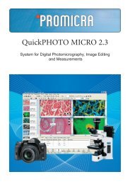
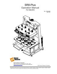
<strong>Lambda</strong> <strong>20</strong>, <strong>Lambda</strong> <strong>40</strong> UV/Vis SpectrometersDeuterium lamps <strong>and</strong> other spectral lamps are maintained under reduced pressure.When you dispose of lamps that are defective or otherwise unusable, h<strong>and</strong>le themcorrectly to minimize the implosion risk.UV RadiationYou should be aware of the health hazards presented by ultraviolet radiation.• When the deuterium (UV) lamp is illuminated, do not open thespectrophotometer covers unless specifically instructed to do so in the manual.• Always wear UV-absorbing eye protection when the deuterium lamp isexposed.• Never gaze into the deuterium lamp.Symbols Used on the InstrumentWarning symbol shown on thespectrometer housingFigure 1 <strong>Lambda</strong> <strong>20</strong>/<strong>40</strong> Spectrometers14
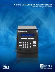
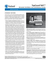
Safety InformationWarning Labels on the InstrumentWarning labels shown on theinside of the lamp compartmentFigure 2 <strong>Lambda</strong> <strong>20</strong>/<strong>40</strong> Spectrometers15
<strong>Lambda</strong> <strong>20</strong>, <strong>Lambda</strong> <strong>40</strong> UV/Vis SpectrometersThe following warnings are shown on the inside of the lamp compartment.DANGERHIGHVOLTAGEDANGERHAUTETENSIONWARNINGUV RADIATION-HARMFUL TO THE EYESHOT COMPONENTS – RISK OF BURNSACHTUNGUV-STRAHLUNG-GEFÄHRDUNG DER AUGENHEISSE BAUTEILE –VERBRENNUNGSGEFAHRATTENTIONRADIATION UV-DOMMAGEABLE POURLES YEUX – PARTIES CHAUDESRISQUE DE BRULURES16
Preface 2
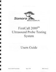
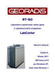
PrefacePrefaceApplicationThe <strong>Lambda</strong> <strong>20</strong> <strong>and</strong> <strong>Lambda</strong> <strong>40</strong> spectrometers are intended for routine UV/Visanalysis. The spectrometer features a double-beam, all-reflecting optical system.<strong>Lambda</strong> <strong>20</strong> <strong>and</strong> <strong>Lambda</strong> <strong>40</strong> spectrometers are usable in a wide range of applicationsas indicated by their performance specifications (see Technical Data on page 83)LampCompartmentKeyboard <strong>and</strong>Display CoverKeyboardPower SwitchSpace forOptional PrinterSample CompartmentConnector PanelFigure 3 Operating controls for <strong>Lambda</strong> <strong>20</strong>/<strong>40</strong> Spectrometers19
<strong>Lambda</strong> <strong>20</strong>, <strong>Lambda</strong> <strong>40</strong> UV/Vis SpectrometersDocumentationA documentation package is provided with the spectrometer:• <strong>Installation</strong> <strong>and</strong> <strong>Maintenance</strong> <strong>Guide</strong>This h<strong>and</strong>book describes the installation, setup, <strong>and</strong> maintenance proceduresfor the spectrometer. It also includes a detailed description of the spectrometer<strong>and</strong> a list of consumables <strong>and</strong> replacement parts.• Operation <strong>Guide</strong>This h<strong>and</strong>book contains comprehensive information on operating thespectrometer <strong>and</strong> describes the parameters used.<strong>20</strong>
Basic <strong>Installation</strong> 3
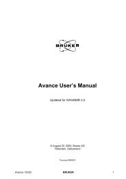
Basic <strong>Installation</strong>Basic <strong>Installation</strong>OverviewFor spectrometers with installation, the initial installation will be performed by aPerkinElmer service representative. After receipt of the instrument, please contactyour PerkinElmer office or representative for further information.For spectrometers without installation, you can easily install the instrument byfollowing the directions given in the table below.If you intend to use accessories, for example a cell changer or sipper, refer toAccessory <strong>Installation</strong> on page 39 to install these accessories.Preparing the Working AreaFor maximum stability <strong>and</strong> minimum maintenance observe the followingrequirements when siting the instrument:• A firm base free from vibration.• Enough space around <strong>and</strong> underneath the instrument for efficient aircirculation.• A constant temperature between 15 ºC <strong>and</strong> 35 ºC.• Constant humidity between <strong>20</strong>% <strong>and</strong> 80% relative humidity.• An atmosphere free from dust <strong>and</strong> corrosive fumes.• Keep out of direct sunlight. Illumination with diffuse lighting is ideal.23
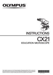
<strong>Lambda</strong> <strong>20</strong>, <strong>Lambda</strong> <strong>40</strong> UV/Vis Spectrometers• A suitable source of electrical power should be located in the vicinity of theinstrument.Electrical power must be available at a proper earth-grounded 3-wire electricaloutlet.Please refer to Technical Data on page 83 for the electrical ratings of thespectrometer.• The st<strong>and</strong>ard sample compartment baseplates have drain holes in them to runoff spilled liquids to the benchtop underneath the instrument. You can place asheet of thick filter paper under the instrument, if required.26 cmFront view65 cmRight side view56 cmFigure 4 Space Requirements24
Basic <strong>Installation</strong>System ConfigurationSpectrometerExternal Printer(option)Figure 5 Components of the System• You can place the (optional) printer to either side of the spectrometer to suityour own preferences.• Do not place the printer or other instruments on top of the spectrometer.• When placing instruments side by side, always leave a small gap betweenthem.• If you wish, you can set up the printer on a separate trolley (cart).• Make certain that air can circulate freely over <strong>and</strong> under the system as well asbehind it.CAUTIONDo not place anything on or under any of the components that couldhinder free air circulation.27
<strong>Lambda</strong> <strong>20</strong>, <strong>Lambda</strong> <strong>40</strong> UV/Vis SpectrometersConnecting to the Electrical SupplyElectrical HazardWARNING• To prevent potential injury to yourself <strong>and</strong> damage to theinstrument, first make the electrical connections between theinstruments in the system before connecting to the line powersupply.• The spectrometer automatically adjusts to the correct operatingvoltage.Before starting the instrument for the first time, make sure that thecorrect fuse is fitted to your line power supply.If you have a different fuse, change it for the correct one.Do not connect the spectrometer to the line power supply if thewrong fuse is fitted.1. Make sure that the correct fuses are fitted in the holder at the rear of thespectrometer (see Changing Fuses on page 65).VoltageSt<strong>and</strong>ard100 V – 1<strong>20</strong> V 6.3 A slow-blow210 V – 2<strong>40</strong> V 3.15 A slow-blowNOTE: The module has two fuses.2. Make sure that the plug fitted to the line power cord provided with thespectrometer is suitable for your local electrical outlets.If it is not, remove it <strong>and</strong> fit a plug conforming to the local regulations.3. After all connections have been made between the various components of thesystem, make certain that all power switches are set to off, then connect theline cords to the electrical power supply.The power switch is located at the top right-h<strong>and</strong> rear of the spectrometer.28
Basic <strong>Installation</strong>NOTE: To prevent interferences caused by earth loops when operating with ancillaryinstruments (printers, etc.), connect all components of the system to the same phaseof the electrical supply via a multisocket distributor.Single Cell HolderLocking screwfor horizontalalignmentVertical adjustmentscrewLifterMilled postLocking screwfor horizontalalignmentFigure 6 Single Cell Holder B0505071NOTE: Depending on the spectrometer, the single cell holder can be installed in twodifferent positions in the sample compartment. Always install the holder such thatthe arrow on the cell holder lines up with the center point on the baseplate (seeInstalling the Cell Holder on page 30).29
<strong>Lambda</strong> <strong>20</strong>, <strong>Lambda</strong> <strong>40</strong> UV/Vis SpectrometersInscription legibleon HolderLAMBDABIO LAMBDA 2Use in SpectrometerIn this position, the cell holder can be used with all<strong>Lambda</strong> Series Spectrometers.In this position, the cell holder can be used with <strong>Lambda</strong>2 Series Spectrometers as <strong>Lambda</strong> 10, <strong>20</strong>, <strong>40</strong>, Bio, etc.(baseplate with 4 threaded holes).The smallest beam diameter is exactly in the middle ofthe cell. This is useful especially for operation withmicro <strong>and</strong> semi-micro cells.Installing the Cell HolderInstall the single cell holder in the sample compartment as follows:1. Orientate the holder so that the lifter is toward the rear of the samplecompartment.2. Lower the holder so that the two alignment holes slip onto the two studs on thebaseplate at the bottom of the sample compartment.The arrow on the cell holder must line up with the centre point of the baseplate,<strong>and</strong> BIO LAMBDA 2 must be legible.Tube PortsBIOLAMBDA 2ArrowCenter Point30
Basic <strong>Installation</strong>3. Move the milled posts a little to locate the threaded holes in the baseplate, <strong>and</strong>then tighten the milled posts.The tube ports located at the front of the sample compartment allow you to leadtubes from flowcells, water-thermsotatted cell holders, etc. in <strong>and</strong> out of thesample compartment.When not in use, you should always insert the caps into the ports.Aligning the Single Cell HolderCoarse alignment of the single cell holder is carried out as follows:1. Open the sample compartment cover.2. Fill matching cells with a low-absorbing solvent (deionized water or ethanol).3. Insert one cell into the sample cell holder <strong>and</strong> one into the reference cell holder.Make certain that the cell is pushed down fully.NOTE: The alignment procedure is for a given cell in a given holder. After alignment, thecell should always be used in the same holder.4. Block the sample <strong>and</strong> reference beam window on the right h<strong>and</strong> side of thesample compartment with a card to prevent white light from saturating thedetector.5. Return to st<strong>and</strong>by display.6. Using the [GOTO] key, slew the monochromator to 0 nm to obtain a beam ofvisible (zero order) radiation in the sample compartment.7. By holding a piece of matt white paper behind each cell holder, visuallyexamine the light spot to see that the radiation beam is passing through the cellsample area.Diffraction patterns become apparent if the radiation beam impinges on the cellwall.31
<strong>Lambda</strong> <strong>20</strong>, <strong>Lambda</strong> <strong>40</strong> UV/Vis Spectrometers8. If the radiation beam is not centered exactly, loosen the two locking screws <strong>and</strong>the two milled posts on the relevant cell holder <strong>and</strong> shift the cell holder plate tocenter the radiation beam horizontally.Then retighten the two milled posts <strong>and</strong> the two locking screws.9. Now visually check the vertical alignment of the radiation beam in the cellsample area.Alignment is correct when the radiation beam is just above the floor of the cellsample area (min. 2 mm) or covers the cell window.NOTE: The center of the window for micro flowcells should be ideally approximately15 mm above the base of the cell.Min. 2 mmFigure 7 Correct Alignment of the Radiation Beam in the Cell Sample Area10. If vertical alignment is required, turn the vertical adjustment screw on the liftereither clockwise to raise the cell, or counterclockwise to lower the cell.11. Recheck the horizontal alignment of the radiation beam through the cell <strong>and</strong>correct if necessary.12. Using the [GOTO] key, slew the monochromator to any value above <strong>20</strong>0 nm.13. Remove the card blocking the sample beam window <strong>and</strong> close the samplecompartment cover.32
Basic <strong>Installation</strong>This completes the coarse alignment of the cell holder. If necessary, proceed withthe fine alignment as described below.Fine AlignmentIf fine alignment is necessary, proceed as follows:1. Using the [GOTO] key, slew the monochromator to your measurementwavelength or to 460 nm.2. Call up a method that uses transmission (%T) as the ordinate.If necessary change the ordinate mode to transmission.3. Open the sample compartment cover.4. Insert the cell with a low absorbing solvent into the sample cell holder.Leave the reference cell holder empty.5. Make horizontal fine alignment to the sample cell holder (locking screws <strong>and</strong>milled posts loosened) to obtain the highest possible transmittance reading onthe display (close sample compartment cover while measuring transmittance).6. Make vertical fine adjustment using the vertical adjustment screw again toobtain the highest possible reading (close sample compartment cover whilemeasuring transmittance).7. When you are satisfied with the alignment, tighten the milled posts <strong>and</strong> thelocking screws on the cell holder.8. Insert the matching cell with the same low absorbing solvent into the referencecell holder.The first cell remains in the sample cell holder.9. Repeat steps 5 to 7 with the reference cell holder, but this time obtain thelowest possible transmittance reading on the display.This completes the fine alignment procedure.33
<strong>Lambda</strong> <strong>20</strong>, <strong>Lambda</strong> <strong>40</strong> UV/Vis SpectrometersWhen the cell holder has been aligned once, you can take it out <strong>and</strong> reinstall itwithout aligning it again.Minimum Volume ApplicationsTo measure minimum sample volumes, use microcells (offered by PerkinElmer).The minimum sample volume required is a function of the cell internal width orvolume <strong>and</strong> is specified below.Cell TypeCellInternalWidthPathlengthMinimumVolumeRequiredPartNumberHeight ofliquid slightlymore thanheight ofbeam2 mm 1 cm <strong>20</strong>0 µL B0631071(pair)4 mm 1 cm <strong>40</strong>0 µL B0631064(pair)CellVolumePathlengthMinimumVolumeRequiredPartNumberCell windowcompletelyfilled withliquid0.5 µL 0.01 cm 2 µL B06310822.5 µL 0.5 cm 5 µL B06310805 µL 0.1 cm 10 µL B06310835 µL 1.0 cm 10 µL B063108130 µL 1.0 cm 50 µL B063107934
Basic <strong>Installation</strong>NOTE: You should align microcells very carefully in the radiation beam by following theprocedures in Aligning the Single Cell Holder on page 31. When aligningmicrocells, fill each cell with the minimum volume of liquid specified in the abovetable to make sure that the liquid meniscus is not in the radiation beam.Setting up the PrinterActivating the Internal PrinterIf you want to use the internal printer, make sure the method PRINTER CONFIG. isset to EPSON/INTERNAL in Super User. On delivery, the default setting isEPSON/INTERNAL.Connecting an External PrinterYou can use an external printer for hard-copy printouts of the analytical results.PerkinElmer offers suitable printers; refer to the current price list for details.To install an external printer:1. Switch off the spectrometer, if it is on.2. Set up the printer as given in the User’s <strong>Guide</strong> provided with the printer.3. Configure the printer.4. Connect the printer to the Parallel Port.If you connect the printer to the second RS 232 interface, make sure theInstrument Configuration method is set correctly in Super User.5. Switch on the spectrometer <strong>and</strong> the printer to activate the new printerconfiguration.6. Make sure the method PRINTER CONFIG. is set correctly for the connectedprinter in Super User.35
<strong>Lambda</strong> <strong>20</strong>, <strong>Lambda</strong> <strong>40</strong> UV/Vis SpectrometersSpectrometerPrinterPrinter CableFigure 8 Connecting an External Printer to the Parallel PortConfiguring an External PrinterMake sure the spectrometer is correctly configured for your printer type as describedin Super User printer configuration in the Operation h<strong>and</strong>book.With Epson printers make sure the printer parameter is configured correctly for thetype of paper you are using, Z-fold paper or single sheet.36
Accessory<strong>Installation</strong>4
Accessory <strong>Installation</strong>Accessory <strong>Installation</strong>GeneralTo operate the spectrometer with some accessories, for example the PeltierTemperature sensor, you need an accessory printed circuit board (PCB) <strong>and</strong> aconnector panel. They will be installed by PerkinElmer service.Procedures for installing the accessories in the spectrometer are described in thedirections provided with the respective accessory.To install certain accessories you need to remove the sample compartment cover.The required procedures are described below.In the directions provided with some sample h<strong>and</strong>ling accessories, reference is madeto earlier models in the <strong>Lambda</strong> Series of spectrometers. These directions aregenerally applicable to the current series of instruments since the samplecompartment is st<strong>and</strong>ardized.Accessory Connector Panel (LP5/5)To facilitate manufacturing procedures, a common connector panel is used for the<strong>Lambda</strong> Series of instruments. Not all connectors are required for <strong>Lambda</strong> <strong>20</strong>, or<strong>Lambda</strong> <strong>40</strong> (see table below).39
<strong>Lambda</strong> <strong>20</strong>, <strong>Lambda</strong> <strong>40</strong> UV/Vis SpectrometersJ11AutosamplerCell ChangerSipperJ142 nd RS232J6TempJ10Peltier J30Sphere J8J1P15Accessory PortSerial PortParallel PortDesignation Connector for RemarksAccessory PortLinear transporter,multi-sipperI 2 C-bus interfaceSerial Port PC, (printer) First RS 232 C interfaceParallel Port Printer Centronics interfaceJ6, Autosampler AS90/91 autosamplerJ14, Cell Changer, Sipper Older accessories ActiveP15, 2 nd RS 232 PC, printer Second RS 232 CinterfaceJ10, J11, Temp Temperature sensor J10: 2-pin socketJ11: 4-pin socketJ30, Peltier Peltier cell changer<strong>and</strong> Peltier cell holderActive<strong>40</strong>
Accessory <strong>Installation</strong>J88, Sphere Integrating Sphere ActiveJ1 Pump for dissolution ActiveAccessory ConnectionsAutosamplerPeltier Cell HolderOlderAccessoriesLinear TransporterAutosampler J6CellChangerSipper J14P152 nd RS232Accessory PortSerial PortTempJJ10JJ11Peltier J30Sphere J8JJ1Parallel PortPeltier Cell ChangerTemperature SensorExternal PrinterMulti-sipperPC41
<strong>Lambda</strong> <strong>20</strong>, <strong>Lambda</strong> <strong>40</strong> UV/Vis SpectrometersSample Compartment CoverSome of the accessories used with the spectrometer require removal of the samplecompartment cover.1. Do this carefully as follows:2. Open the cover only about 90 degrees to the sample compartment.3. Carefully slide the cover straight up off both hinges to remove.You install the sample compartment cover, or other accessory cover, byperforming this procedure in reverse.Sample Compartment Front CoverSome of the accessories used with the spectrometer require removal of the samplecompartment front cover.Do this carefully as follows:1. Open the sample compartment cover.2. Carefully slide the cover straight up off both hinges to remove.You install the sample compartment cover, or other accessory cover, byperforming this procedure in reverse.Sample Compartment WindowTo remove or install certain accessories, you need to remove the samplecompartment windows.Each window has a magnetic frame <strong>and</strong> can be easily removed by h<strong>and</strong>.42
Accessory <strong>Installation</strong>Linear TransporterWARNINGElectrical hazardTo prevent potential injury to yourself <strong>and</strong> damage to the instrument,switch OFF all instruments in the system <strong>and</strong> disconnect them from theline power supply before you alter, or make any new, electricalconnections.<strong>Installation</strong> OverviewConnector on Spectrometer:<strong>Installation</strong>:Cables:Tubes:Sample Compartment Cover:Alignment:Accessory PortSee linear transporter h<strong>and</strong>bookLead through bottom of spectrometer housingLead through the tube portsUnchangedSee linear transporter h<strong>and</strong>book43
<strong>Lambda</strong> <strong>20</strong>, <strong>Lambda</strong> <strong>40</strong> UV/Vis SpectrometersTemperature SensorWARNINGElectrical hazardTo prevent potential injury to yourself <strong>and</strong> damage to the instrument,switch OFF all instruments in the system <strong>and</strong> disconnect them from theline power supply before you alter, or make any new, electricalconnections.<strong>Installation</strong> OverviewNOTE: When connecting the temperature sensor, align the red mark on the plug with the redmark on the socket.Pull the collar on the plug back to connect/disconnect the plug. Release the collar tosecure the plug.Connector on Spectrometer:<strong>Installation</strong>:Cables:Sample Compartment Cover:Temp J10See temperature sensor descriptionLead through the tube portsUnchanged44
Accessory <strong>Installation</strong>Multi-sippersWARNINGElectrical hazardTo prevent potential injury to yourself <strong>and</strong> damage to the instrument,switch OFF all instruments in the system <strong>and</strong> disconnect them from theline power supply before you alter, or make any new, electricalconnections.<strong>Installation</strong> OverviewConnector on Spectrometer:<strong>Installation</strong>:Cables:Tubes:Sample Compartment Cover:Accessory PortSee sipper manualSee sipper manualSee sipper manualUnchangedSpectrometerMulti-sipperB0167808Figure 9 Multi-sipper, electrical connection45
<strong>Lambda</strong> <strong>20</strong>, <strong>Lambda</strong> <strong>40</strong> UV/Vis SpectrometersAutosamplerWARNINGElectrical hazardTo prevent potential injury to yourself <strong>and</strong> damage to the instrument,switch OFF all instruments in the system <strong>and</strong> disconnect them from theline power supply before you alter, or make any new, electricalconnections.<strong>Installation</strong> OverviewConnector on Spectrometer:<strong>Installation</strong>:Cables:Tubes:AutosamplerSee autosampler manualSee autosampler manualSee autosampler manualSpectrometerAutosamplerB0509311Figure 10 Autosampler electrical connection46
Accessory <strong>Installation</strong>Personal ComputerYou can connect a personal computer (PC) to the spectrometer via the Serial Port(RS 232 port).Make sure that the Serial Port (RS 232 port) is configured for use with a PC(default), see Super User method RS232 PORT CONFIG.To operate the spectrometer via the PC, you additionally require a PerkinElmer UVsoftware package, for example, UV WinLab, PECSS. Ask your PerkinElmer servicerepresentative for more details.47
<strong>Lambda</strong> <strong>20</strong>, <strong>Lambda</strong> <strong>40</strong> UV/Vis Spectrometers48
<strong>Maintenance</strong> 5
<strong>Maintenance</strong><strong>Maintenance</strong>Obtaining ServiceAll internal servicing of the instrument should be performed by a PerkinElmerservice representative or similarly authorized person.Please contact your local PerkinElmer sales or service office to obtain service.<strong>Maintenance</strong> procedures that you can perform yourself are described in this chapter.WARNINGUnauthorized Adjustments <strong>and</strong> ServicingDo not attempt to make adjustments, replacements or repairs to thisinstrument except as described in the accompanying UserDocumentation.Only a PerkinElmer service representative or similarly trained <strong>and</strong>authorized person should be permitted to service the instrument.Daily CareThe instrument is constructed with high quality components <strong>and</strong> requires littlemaintenance other than to keep it clean <strong>and</strong> free of dust.To protect the optical system from dust <strong>and</strong> fumes, you should keep the samplecompartment cover closed except for when you are carrying out work in thecompartment.The sample compartment windows should always be installed.51
<strong>Lambda</strong> <strong>20</strong>, <strong>Lambda</strong> <strong>40</strong> UV/Vis SpectrometersYou should observe the following care routine to maintain your instrument in goodcondition:• Immediately clean all spilled materials from the affected area <strong>and</strong> wipe it drywith lintless paper or cloth.If you have to wipe the sample compartment windows, make sure you do notintroduce scratches.Sample windows are optical components <strong>and</strong> you should h<strong>and</strong>le them in thesampe way as high quality cells.• Do not leave samples, particularly those given to fuming or evaporation, in thesample compartment for longer than necessary.• If any type of sample h<strong>and</strong>ling system is installed <strong>and</strong> portions of it are left inthe sample compartment (such as a sipper <strong>and</strong> flowcell), make certain that thesystem is cleaned at the end of the working day.Generally, such systems should be filled with deionized water when leftovernight.CAUTIONRisk of damage to Optics or ElectronicsTake care not to spill liquids onto the spectrometer. Expensive damagecan result to the optics or electronics if liquids are spilled <strong>and</strong> runinside the instrument or onto the keyboard.Cleaning the Sample CompartmentYou must clean the sample compartment every time anything is spilled into it. Thispreserves the matt black finish, <strong>and</strong> prevents corrosion <strong>and</strong> contamination.The st<strong>and</strong>ard sample compartment baseplates have drain holes in them to run offspilled liquids to the benchtop underneath the instrument. You can place a sheet ofthick filter paper under the instrument, if required.1. First remove the cell holder or other sample h<strong>and</strong>ling accessory from thesample compartment.52
<strong>Maintenance</strong>2. Using a soft cloth <strong>and</strong> mild laboratory detergent solution, lightly scrub away allforeign material.3. Using a clean cloth dampened with water, rinse the cleaned surfacesthoroughly.4. Dry with lint free cloth or tissue.Sample Compartment WindowWindows are provided with the spectrometer. The window is made of silica <strong>and</strong> maybe used in the entire spectral range of the spectrometer.The window seals the sample compartment <strong>and</strong> thus protects the instrument’s opticsfrom dust <strong>and</strong> fuming or aggressive samples.• Generally, the window should be installed at all times.• The window is an optical component <strong>and</strong> requires the same care <strong>and</strong> h<strong>and</strong>lingas cells.• You can remove the window to clean it. The frame is magnetic <strong>and</strong> can beremoved by h<strong>and</strong>.Windows are most suitably cleaned by wiping them with a soft cloth moistenedwith ethanol.53
<strong>Lambda</strong> <strong>20</strong>, <strong>Lambda</strong> <strong>40</strong> UV/Vis SpectrometersUse <strong>and</strong> Care of CellsCell H<strong>and</strong>lingA good spectrometer cell is an optical device, forming a part of the optical system ofthe instrument with which it is used. It must be accorded the same careful treatmentapplied to any optical component. Optical faults of a minor nature, scratches, lint,fingermarks, etc. on the optical surfaces can easily introduce substantial analyticalerrors.You should observe the following list of cell h<strong>and</strong>ling rules to prevent analyticalerrors <strong>and</strong> to achieve utmost precision:• Only hold cells by non-optical surfaces, such as the matt finish surfaces.• Protect cells from scratches, <strong>and</strong> never permit them to rub against one anotheror against other hard surfaces.• Avoid abrasive, corrosive or stain-producing cleaning agents, <strong>and</strong> make certainthat the exposed surfaces of cells are optically clean.• Always wipe the optical surfaces of cells dry <strong>and</strong> free of fingermarks, using asoft cloth or cleaning tissue, just before placing them in the cell holder.• When measuring cold solutions, always bear in mind that condensation canform on the optical surfaces.• Make certain no bubbles cling to the inner surfaces of the cell, particularlywhen h<strong>and</strong>ling cold solutions.• For maximum precision <strong>and</strong> accuracy, calibrate <strong>and</strong> test with cells of the sametype, <strong>and</strong> always insert cells into the holders with the same orientation.Pressure Buildup in CellsIf you are using stoppered cells, observe the following rules to prevent the buildupof internal pressure that could cause the cell to burst:54
<strong>Maintenance</strong>• Only fill the cell so full that the liquid meniscus is just above the radiationbeam. The remaining air space in the cell is then adequate to compensate forany slight increase in pressure in the cell during routine operation.• If, for analytical reasons, it is necessary to fill the cell completely, insert thestopper only lightly so that the liquid in the cell has a chance to exp<strong>and</strong>.• Do not insert a stopper forcefully into a completely filled cell since this islikely to cause the cell to burst.• When working at higher temperatures, use a drilled stopper (0.4 mm hole) toallow for expansion in the cell.Replacing a LampLamp compartmentFigure 11 Lamp compartment55
<strong>Lambda</strong> <strong>20</strong>, <strong>Lambda</strong> <strong>40</strong> UV/Vis SpectrometersWhite ceramicconnectorDeuterium lampconnectorHalogen lampassemblyDeuterium lampassemblyLamp energyattenuatorFigure 12 Inside the Lamp Compartment (Baffle removed)Halogen Lamp ReplacementIf the lamp burns out, or if the bulb becomes blackened after prolonged use, youshould replace the lamp.Replacement lamp assemblies are provided complete with prealigned mounts (PartNumber B01146<strong>20</strong>).56
<strong>Maintenance</strong>Figure 13 Prealigned Halogen Lamp (B01146<strong>20</strong>)WARNINGElectrical HazardSwitch off the spectrometer <strong>and</strong> remove the plug from the electricalsupply before starting with the replacement.Risk of BurnsIf the old lamp was lighted: allow it to cool before proceeding with thereplacement.UV RadiationThe lamps emit intense radiation which can damage your eyes.Do not open the lamp compartment when the lamps are on.Do not gaze into a lighted lamp.1. Switch off the spectrometer <strong>and</strong> unplug the line power cord.2. Remove the lamp compartment cover by pressing down the catch <strong>and</strong> pushingthe cover to the left.3. Remove the lamp baffle by slackening the thumbscrew for the deuterium lamp<strong>and</strong> lifting the lamp baffle vertically upward.57
<strong>Maintenance</strong>5. Remove the lamp assembly from the bracket by slackening the thumbscrew<strong>and</strong> pulling the lamp mount vertically upward.Save the thumbscrew for use with the new lamp assembly.6. Unpack the new lamp assembly, taking care to hold it only by the metal mountto prevent fingermarks on the bulb.7. Slip the slot at the base of the lamp mount over the stud on the bracket in thelamp compartment <strong>and</strong> then secure with the thumbscrew.8. Carefully push the ceramic connector firmly onto the pins on the base of thelamp.9. Wipe the bulb with a soft cloth moistened with alcohol to remove dirt, sincethis would otherwise be burned in when the lamp is hot.10. Replace the lamp baffle using the reverse of the procedure described in step 3.11. Replace the lamp compartment cover.This completes the halogen lamp replacement procedure.Deuterium Lamp ReplacementIf the lamp burns out, or indicates falling energy after prolonged use, you shouldreplace the lamp.Replacement lamp assemblies are provided complete with prealigned mounts (PartNumber B<strong>20</strong>00501).59
<strong>Lambda</strong> <strong>20</strong>, <strong>Lambda</strong> <strong>40</strong> UV/Vis SpectrometersOperating HoursCounterFigure 14 Prealigned Deuterium Lamp Assembly (B<strong>20</strong>00501)NOTE: An operating hours counter is incorporated in the red deuterium lamp lead.By means of a gap between the two display bars it is possible to read off the numberof hours that the lamp has been in operation.One scale division corresponds to approximately 100 hours.WARNINGElectrical HazardSwitch off the spectrometer <strong>and</strong> remove the plug from the electricalsupply before starting with the replacement.Risk of BurnsIf the old lamp was lighted: allow it to cool before proceeding with thereplacement.UV RadiationThe lamps emit intense radiation which can damage your eyes.Do not open the lamp compartment when the lamps are on.Do not gaze into a lighted lamp.1. Switch off the spectrometer <strong>and</strong> unplug the line power cord.2. Remove the lamp compartment cover by pressing down the catch <strong>and</strong> pushingthe cover to the left.3. Remove the lamp baffle by slackening the thumbscrew for the deuterium lamp<strong>and</strong> lifting the lamp baffle vertically upward.60
<strong>Maintenance</strong>Lamp baffleThumbscrew(deuterium lamp)4. Unplug the deuterium lamp connector from the terminal board by squeezing inthe two lugs at each side of the connector <strong>and</strong> carefully pulling the connectorvertically upward.Deuterium lampconnectorDeuterium lampassembly5. Remove the lamp assembly from the bracket by slackening the thumbscrew<strong>and</strong> pulling the lamp mount vertically upward.Save the thumbscrew for use with the new lamp assembly.61
<strong>Lambda</strong> <strong>20</strong>, <strong>Lambda</strong> <strong>40</strong> UV/Vis Spectrometers6. Unpack the new lamp assembly, taking care to hold it only by the metal mountto prevent fingermarks on the lamp window.7. Slip the slot at the base of the lamp mount over the stud on the bracket in thelamp compartment <strong>and</strong> then secure with the thumbscrew.8. Plug the deuterium lamp connector into the socket.NOTE: The socket in the lamp compartment is asymmetric; the deuterium lamp connector canbe inserted in one direction only. Make certain that the connector is the right wayround before inserting it. Never attempt to insert the connector by force.9. Wipe the lamp window with a soft cloth moistened with alcohol to remove dirt,since this would otherwise be burned in when the lamp is hot.10. Replace the lamp baffle using the reverse of the procedure described in step 3.11. Replace the lamp compartment cover.This completes the deuterium lamp replacement procedure.Lamp Energy AttenuatorAn attenuator is located in the lamp compartment between the deuterium lamp <strong>and</strong>the beam entrance slit.If required you can decrease or increase the energy by placing the attenuator into, ortaking the attenuator out of, the beam.The attenuator is set at the factory, normally in the out position.62
<strong>Maintenance</strong>WARNINGElectrical HazardSwitch off the spectrometer <strong>and</strong> remove the plug from the electricalsupply before starting with the replacement.Risk of BurnsIf the old lamp was lighted: allow it to cool before proceeding with thereplacement.UV RadiationThe lamps emit intense radiation which can damage your eyes.Do not open the lamp compartment when the lamps are on.Do not gaze into a lighted lamp.Operate the attenuator as follows:1. Open the lamp compartment.2. Remove the lamp baffle by slackening the thumbscrew for the deuterium lamp<strong>and</strong> lifting the lamp baffle vertically upward.Lamp baffleThumbscrew(deuterium lamp)3. Loosen the thumbscrew holding the attenuator in place.63
<strong>Lambda</strong> <strong>20</strong>, <strong>Lambda</strong> <strong>40</strong> UV/Vis SpectrometersDeuterium lampassemblyLamp energyattenuator4. Slide the attenuator downwards into the beam.5. Tighten the thumbscrew.6. Follow the above procedure in reverse to slide the attenuator out of the beam.7. Replace the lamp baffle using the reverse of the procedure described in step 2.8. Close the lamp compartment.Lamp Alignment ProcedureDue to the prealigned mounts, the alignment of lamps after installation is generallyso good that further alignment is not required.64
<strong>Maintenance</strong>Changing FusesWARNINGElectrical hazardTo prevent potential injury to yourself <strong>and</strong> damage to the instrument,switch OFF all instruments in the system <strong>and</strong> disconnect them from theline power supply before you alter, or make any new, electricalconnections.The fuses are located in a fuse holder at the rear of the instrument:Fuse HolderFigure 15 Rear view, Fuse Holder1. Switch off the instrument <strong>and</strong> remove the line power cord from the electricalsupply.2. Squeeze the two lugs at each side of the fuse holder <strong>and</strong> gently pull out.Fuse Holder65
<strong>Lambda</strong> <strong>20</strong>, <strong>Lambda</strong> <strong>40</strong> UV/Vis Spectrometers3. Replace the spent fuse with a new one of the same type <strong>and</strong> rating:VoltageSt<strong>and</strong>ard100 V – 1<strong>20</strong> V 6.3 A slow-blow210 V – 2<strong>40</strong> V 3.15 A slow-blowNOTE: The module has two fuses.4. Replace the fuse holder.Align the lug at the bottom of the fuse holder with the slot in the socket. Aclick is heard as each lug snaps into place.NOTE: If you use the correct fuses but the instrument still does not work correctly, or thefuses blow repeatedly, contact your PerkinElmer office or representative.Maintaining the Internal PrinterThe internal printer needs no special maintenance. You only need to:• Change the printer paper• Change the printer ribbonwhen necessary.Changing the Printer Paper1. Lift off <strong>and</strong> remove the old paper roll.2. Replace with a new paper roll.3. Cut square the end of the paper.4. Carefully feed the end of the paper into the slot at the top of the printer.66
<strong>Maintenance</strong>5. Press 4 Print to feed the paper through the printer until it appears at the front.Changing the Printer Ribbon1. Lift off <strong>and</strong> remove the paper roll.2. Push in the catch on the printer cover.3. Carefully lift out the printer.4. Gently pull the ribbon cassette forwards to remove.5. Replace with a new one.6. Replace the printer <strong>and</strong> printer cover using the reverse of the above procedure.67
<strong>Lambda</strong> <strong>20</strong>, <strong>Lambda</strong> <strong>40</strong> UV/Vis Spectrometers68
Replacement Parts 6
Replacement PartsReplacement PartsSupplies, accessories, <strong>and</strong> replacement parts can be ordered directly fromPerkinElmer. PE XPRESS, PerkinElmer’s catalog service, offers a full selection ofhigh-quality ultraviolet, fluorescence, <strong>and</strong> polarimetry supplies through the SuppliesCatalog for Ultraviolet/Visible <strong>and</strong> Fluorescence Spectroscopy <strong>and</strong> Polarimetry.To place an order, request a free catalog, or ask for information:If you are located within the U.S., call toll free 1-800-762-<strong>40</strong>2, 8 a.m. to 8 p.m. EST.Your order will be shipped promptly, usually within 24 hours.If you are located outside of the U.S., call your local PerkinElmer sales office.71
<strong>Lambda</strong> <strong>20</strong>, <strong>Lambda</strong> <strong>40</strong> UV/Vis SpectrometersQuantity Item Part NumberFuses <strong>and</strong> Cables10 3.15 A slow-blow B015557310 6.3 A slow-blow B01555761 RS 232 printer cable B0166569Lamps <strong>and</strong> Windows1 Deuterium Lamp, prealigned B<strong>20</strong>005011 Halogen Lamp, prealigned B01146<strong>20</strong>1 Thumbscrew for lamp mount B01193711 Sample Compartment Window B0098757Cells <strong>and</strong> Cell HolderCells see actual price list1 Single Cell Holder B0505071Miscellaneous5 Paper Roll for internal printer B05087511 Ribbon for internal printer B050875272
System Description 7
System DescriptionSystem DescriptionFeaturesKeyboard <strong>and</strong>Display CoverLamp compartmentPower switchSample compartmentConnector panelFigure 16 <strong>Lambda</strong> <strong>20</strong>, <strong>40</strong> Spectrometer FeaturesOptical System <strong>Lambda</strong> <strong>20</strong>The <strong>Lambda</strong> <strong>20</strong> UV/Vis Spectrometer features an all-reflecting optical system. Theoptical components are coated with silica for durability. A holographic grating isused in the monochromator.The optical system is depicted schematically in Figure 17.The monochromator is a holographic concave grating with 1053 lines/mm inthe center.Two radiation sources, a deuterium lamp <strong>and</strong> a halogen lamp, cover the workingwavelength range of the spectrometer.75
<strong>Lambda</strong> <strong>20</strong>, <strong>Lambda</strong> <strong>40</strong> UV/Vis SpectrometersFor operation in the visible (Vis) range, mirror M1 reflects the radiation from thehalogen lamp onto source mirror M2. At the same time M1 blocks the radiationfrom the deuterium lamp.For operation in the ultraviolet (UV) range, mirror M1 is raised to permit radiationfrom the deuterium lamp to strike source mirror M2.Source change is automatic during monochromator slewing.Radiation from the source lamp is reflected from source mirror M2 through anoptical filter on the filter wheel assembly.A stepping motor drives the filter wheel to be in sychronization with themonochromator.Depending on the wavelength being produced, the appropriate optical filter islocated in the beam path to prefilter the radiation before it enters themonochromator.Filter change is automatic during monochromator slewing.From the optical filter the radiation passes through the entrance slit (Slit 1) of themonochromator.The radiation is dispersed at the grating to produce a spectrum. The rotationalposition of the grating effectively selects a segment of the spectrum, reflecting thissegment through the exit slit (Slit 2) to mirror M3.76
System DescriptionHalogenlampM2M = MirrorM1, M4, <strong>and</strong> M5 = Plane MirrorM2 = Toroidal MirrorM3 = Spherical MirrorDeuteriumlampM1Filter wheelSlit 1M5ReferenceDetectorLensSlit 2M3Beam SplitterGrating(Monochromator)M4SampleLensDetectorFigure 17 Optical Path for <strong>Lambda</strong> <strong>20</strong>The exit slit restricts the spectrum segment to a near-monochromatic radiation beam.The slits provide a spectral b<strong>and</strong>pass of 1 nm, or 2 nm.From mirror M3 the radiation is reflected onto a beam splitter which allows 50% ofthe radiation to pass onto plane mirror M4, <strong>and</strong> reflects 50% of the radiation ontoplane mirror M5.Mirror M4 focuses the radiation beam in the sample cell.77
<strong>Lambda</strong> <strong>20</strong>, <strong>Lambda</strong> <strong>40</strong> UV/Vis SpectrometersThe beam then passes through a convex lens onto the photodiode detector.Mirror M5 focuses the radiation beam in the reference cell.The beam then passes through a convex lens onto the photodiode detector.Optical System <strong>Lambda</strong> <strong>40</strong>The optical system is depicted schematically in Figure 18.The <strong>Lambda</strong> <strong>40</strong> UV/Vis Spectrometer features an all-reflecting optical system. Theoptical components are coated with silica for durability. A holographic grating isused in the monochromator.The monochromator is a holographic concave grating with 1053 lines/mm in thecenter.Two radiation sources, a deuterium lamp <strong>and</strong> a halogen lamp, cover the workingwavelength range of the spectrometer.For operation in the visible (Vis) range, mirror M1 reflects the radiation from thehalogen lamp onto source mirror M2. At the same time M1 blocks the radiationfrom the deuterium lamp. For operation in the ultraviolet (UV) range, mirror M1 israised to permit radiation from the deuterium lamp to strike source mirror M2.Source change is automatic during monochromator slewing.Radiation from the source lamp is reflected from source mirror M2 through anoptical filter on the filter wheel assembly.A stepping motor drives the filter wheel to be in sychronization with themonochromator.Depending on the wavelength being produced, the appropriate optical filter islocated in the beam path to prefilter the radiation before it enters themonochromator. Filter change is automatic during monochromator slewing.From the optical filter the radiation passes through the entrance slit (Selectable Slit1) of the monochromator.78
System DescriptionThe radiation is dispersed at the grating to produce a spectrum. The rotationalposition of the grating effectively selects a segment of the spectrum, reflecting thissegment through the exit slit (Selectable Slit 2) to mirror M3.DeuteriumlampHalogenlampM1M2M = MirrorM1, M4, <strong>and</strong> M5 = Plane MirrorM2 = Toroidal MirrorM3 = Spherical MirrorFilter wheelSelectableSlit 1M5ReferenceM3LensDetectorBeam SplitterSelectableSlit 2LensGrating(Monochromator)M4SampleDetectorFigure 18 Optical Path for <strong>Lambda</strong> <strong>40</strong>The exit slit restricts the spectrum segment to a near-monochromatic radiation beam.The slits provide a spectral b<strong>and</strong>pass of 0.5 nm, 1 nm, 2 nm <strong>and</strong> 4 nm.From mirror M3 the radiation is reflected onto a beam splitter which allows 50% ofthe radiation to pass onto plane mirror M4, <strong>and</strong> reflects 50% of the radiation ontoplane mirror M5.Mirror M4 focuses the radiation beam in the sample cell.79
<strong>Lambda</strong> <strong>20</strong>, <strong>Lambda</strong> <strong>40</strong> UV/Vis SpectrometersThe beam then passes through a convex lens onto the photodiode detector.Mirror M5 focuses the radiation beam in the reference cell.The beam then passes through a convex lens onto the photodiode detector.80
Technical Data 8
Technical DataTechnical Data<strong>Lambda</strong> <strong>20</strong>GeneralTypeScanning double-beam spectrometer for theUV/Vis range; with microprocessor <strong>and</strong>keyboardDimensions Width: 650 nmHeight: 260 nmDepth: 560 nmMassPower requirements26 kg approx.100 V to 2<strong>40</strong> V AC, 50/60 Hz; 250 VAAmbient operating temperature 15 ºC to 35 ºCHumidity rangeTechnical St<strong>and</strong>ardRadio interference suppression<strong>20</strong>% to 80% relative humidity withoutcondensationIn compliance with the requirements fortechnical instruments stipulated byIEC 1010-1/9.90In compliance with the legal requirementsof the EMC directive 89.336/EEC(EN 50 081-1; EN 50 082-1)83
<strong>Lambda</strong> <strong>20</strong>, <strong>Lambda</strong> <strong>40</strong> UV/Vis SpectrometersOpticsBeam center height15 mm above cell holder bottomBeam cross-section 1 mm slit ca. 0.6 mm x 9 mm (width x height)2 mm slit ca. 1 mm x 9 mm (width x height), atfocal point of sample <strong>and</strong> referencebeam in sample compartmentOptical pathlength insample compartmentGrating (Monochromator)Radiation sourcesDetector121 mmHolographic concave grating with 1053 lines/mmin the centerPrealigned deuterium <strong>and</strong> halogen lampsPhotodiodes(One for the sample beam <strong>and</strong> one for thereference beam)AbscissaWavelength rangeWavelength accuracyWavelength reproducibilitySpectral b<strong>and</strong>widthLamp change190 n to 1100 nm;0 nm for alignment purposes±0.3 nm±0.1 nm1 nm or 2 nm (fixed slit)Automatically at 326 nm(selectable over the whole wavelengthrange, see Super User FactoryConfiguration)Scan speeds 7.5, 15, 30 , 60, 1<strong>20</strong>, 2<strong>40</strong>, 480, 960,19<strong>20</strong> <strong>and</strong> 2880 nm/min84
Technical DataOrdinatePhotometric range Transmission 0% to 100%Absorbance –6.000 to 6.000 (display range)1 to 9999 (concentration units)Photometric accuracy Absorbance ±0.003(measured at Absorbance = 1 at 4<strong>40</strong> nm, 546.1 nm <strong>and</strong>630 nm with NIST 930 filters)Absorbance ±0.015(measured at Absorbance = 1, at 257 nm <strong>and</strong> 350 nmwith potassium dichromate solution * )Stray radiation Transmission < 0.02%(at 2<strong>20</strong> nm, 3<strong>40</strong> nm <strong>and</strong> 370 nm)Absorbance > 2(measured at <strong>20</strong>0 nm with potassium chloride solution †against distilled water)Baseline linearity 1 nm slit: Absorbance ±0.0012 nm slit: Absorbance ±0.0005(corrected: <strong>20</strong>0 nm to 100 nm, scan speed 2<strong>40</strong> nm/min,smooth 2)Baseline noise1 nm slit:Absorbance < 0.00008 RMS,Absorbance < 0.0003 peak-to-peak3 min at absorbance = 0, wavelength 500 nm <strong>and</strong>response 2 s)* β(K 2 Cr 2 O 7 ) = 60.06 µg/mL ±0.5% in sulfuric acid c(H 2 SO 4 ) = 0.005 mol/L† β(KC1)= 12 mg/mL ±0.5%85
<strong>Lambda</strong> <strong>20</strong>, <strong>Lambda</strong> <strong>40</strong> UV/Vis SpectrometersBaseline stability(drift)Absorbance < 0.0003 per hour(500 nm, after warmup)Data OutputDigital portDisplayOne RS 232 C interface (serial), for connecting a printer orPC; optional second RS 232 C interfaceInformation, parameters <strong>and</strong> entries are shown on a two linevacuum fluorescence display with <strong>20</strong> alphanumericcharacters per lineMethodsTypesTimedrive, Scan, WavelengthProgram, Concentration Analysis withfactor <strong>and</strong> with Calibration86
Technical Data<strong>Lambda</strong> <strong>40</strong>GeneralTypeScanning double-beam spectrometer for theUV/Vis range; with four selectable slitwidths, microprocessor <strong>and</strong> keyboardDimensions Width: 650 nmHeight: 260 nmDepth: 560 nmMassPower requirements26 kg approx.100 V to 2<strong>40</strong> V AC, 50/60 Hz; 250 VAAmbient operating temperature 15 ºC to 35 ºCHumidity rangeTechnical St<strong>and</strong>ardRadio interference suppression<strong>20</strong>% to 80% relative humidity withoutcondensationIn compliance with the requirements fortechnical instruments stipulated byIEC 1010-1/9.90In compliance with the legal requirementsof the EMC directive 89.336/EEC(EN 50 081-1; EN 50 082-1)87
<strong>Lambda</strong> <strong>20</strong>, <strong>Lambda</strong> <strong>40</strong> UV/Vis SpectrometersOpticsBeam center heightBeam cross-sectionOptical pathlength insample compartmentGrating (Monochromator)Radiation sourcesDetector15 mm above cell holder bottom0.5 mm slit ca. 0.25 mm x 7 mm (width x height)1 mm slit ca. 0.6 mm x 7.5 mm (width x height)2 mm slit ca. 1 mm x 7.5 mm (width x height)4 mm slit ca 2 mm x 7.5 mm (width x height),at focal point of sample <strong>and</strong> reference beam insample compartment121 mmHolographic concave grating with 1053 lines/mmin the centerPrealigned deuterium <strong>and</strong> halogen lampsPhotodiodes(One for the sample beam <strong>and</strong> one for the referencebeam)AbscissaWavelength rangeWavelength accuracyWavelength reproducibilitySpectral b<strong>and</strong>width190 nm to 1100 nm;0 nm for alignment purposes±0.3 nm±0.1 nm0.5 nm, 1 nm, 2 nm, 4 nm(selectable fixed slit widths)88
Technical DataLamp changeAutomatically at 326 nm(selectable over the whole wavelengthrange, see Super User FactoryConfiguration)Scan speeds 7.5, 15, 30 , 60, 1<strong>20</strong>, 2<strong>40</strong>, 480, 960,19<strong>20</strong> <strong>and</strong> 2880 nm/minOrdinatePhotometric range Transmission 0% to 100%Absorbance –6.000 to 6.000 (display range)1 to 9999 (concentration units)Photometric accuracy Absorbance ±0.003(measured at Absorbance = 1 at 4<strong>40</strong> nm, 546.1 nm <strong>and</strong>635 nm with NIST 930 filters)Absorbance ±0.015(measured at Absorbance = 1, at 257 nm <strong>and</strong> 350 nmwith potassium dichromate solution * )Stray radiation Transmission < 0.02%(at 2<strong>20</strong> nm, 3<strong>40</strong> nm <strong>and</strong> 370 nm)Absorbance > 2(measured at <strong>20</strong>0 nm with potassium chloride † solutionagainst distilled water)Baseline linearity 2 nm slit: Absorbance ±0.0005(corrected: <strong>20</strong>0 nm to 100 nm, scan speed 2<strong>40</strong> nm/min,smooth 2)* β(K 2 Cr 2 O 7 ) = 60.06 µg/mL ±0.5% in sulfuric acid c(H 2 SO 4 ) = 0.005 mol/L† β(KC1)= 12 mg/mL ±0.5%89
<strong>Lambda</strong> <strong>20</strong>, <strong>Lambda</strong> <strong>40</strong> UV/Vis SpectrometersBaseline noise2 nm slit:Absorbance < 0.00006 RMS,Absorbance < 0.0002 peak-to-peak3 min at absorbance = 0, wavelength 500 nm <strong>and</strong>response 2 s)Baseline stability(drift)Absorbance < 0.0003 per hour(500 nm, after warmup)Data OutputDigital portDisplayOne RS 232 C interface (serial), for connecting a printer orPC; optional second RS 232 C interfaceInformation, parameters <strong>and</strong> entries are shown on a two linevacuum fluorescence display with <strong>20</strong> alphanumericcharacters per lineMethodsTypesTimedrive, Scan, WavelengthProgram, Concentration Analysis withfactor <strong>and</strong> with Calibration90
Translations ofWarnings9
Translations of WarningsTranslations of WarningsThis annex contains translations of the warnings used in this h<strong>and</strong>book.93
94<strong>Lambda</strong> <strong>20</strong>, <strong>Lambda</strong> <strong>40</strong> UV/Vis Spectrometers
Translations of Warnings95
96<strong>Lambda</strong> <strong>20</strong>, <strong>Lambda</strong> <strong>40</strong> UV/Vis Spectrometers
Translations of Warnings97
98<strong>Lambda</strong> <strong>20</strong>, <strong>Lambda</strong> <strong>40</strong> UV/Vis Spectrometers
Translations of Warnings99
<strong>Lambda</strong> <strong>20</strong>, <strong>Lambda</strong> <strong>40</strong> UV/Vis Spectrometers100
Translations of Warnings101
<strong>Lambda</strong> <strong>20</strong>, <strong>Lambda</strong> <strong>40</strong> UV/Vis Spectrometers102
Index 10
IndexIndexAAccessory Connections, 41Accessory Connector Panel, 39Accessory <strong>Installation</strong>, 39Autosampler, 46General (accessory installation), 39Linear Transporter, 43Multi-sippers, 45Personal Computer, 47Temperature Sensor, 44Autosampler, 46BBasic <strong>Installation</strong>, 23Connecting to the ElectricalSupply, 28Equipment Provided, 26Laboratory Requirements, 23Overview (basic installation), 23Printer, 35Single Cell Holder, 29System Configuration, 27Unpacking <strong>and</strong> Inspection, 25CCleaning the Sample Compartment,52Connecting up the PrinterConfiguring an External Printer, 36DDeuterium Lamp Replacement, 59FusesChanging, 65HHalogen Lamp Replacement, 56IInternal PrinterChanging the Printer Paper, 66Changing the Printer Ribbon, 67Maintaining, 66FL<strong>Lambda</strong> <strong>20</strong>Optical system, 75Technical data, 83<strong>Lambda</strong> <strong>40</strong>Optical system, 78Technical data, 87Lamp Alignment, 64Lamp Energy Attenuator, 62Linear Transporter, 43M<strong>Maintenance</strong>, 51Changing Fuses, 65105
<strong>Lambda</strong> <strong>20</strong>, <strong>Lambda</strong> <strong>40</strong> UV/Vis SpectrometersCleaning the Sample Compartment,52Daily Care, 51Maintaining the Internal Printer, 66Obtaining Service, 51Replacing a Lamp, 55Use <strong>and</strong> Care of Cells, 54Multi-sippers, 45PPersonal Computer, 47Preface, 19Documentation, <strong>20</strong>Preparing the Working Area, 23Pressure Buildup in Cells, 54RReplacement Parts, 71Replacing a Lamp, 55SSafety informationElectromagnetic Compatibility(EMC), 10Safety Information, 7CSA Compliance, 8Electrical Protection, 8Electrical Safety, 8Environment, 12Graphic Symbols Used on theInstrument, 14IEC 1010 Compliance, 8UL Compliance, 8UV Radiation, 14Setting up the Printer, 35Connecting an External Printer, 35Single Cell Holder, 29Aligning, 31Fine Alignment, 33Installing, 30Minimum Volume Applications, 34System Configuration, 27System Description, 75Features, 75Optical System <strong>Lambda</strong> <strong>20</strong>, 75Optical System <strong>Lambda</strong> <strong>40</strong>, 78TTechnical Data, 83<strong>Lambda</strong> <strong>20</strong>, 83<strong>Lambda</strong> <strong>40</strong>, 87Temperature Sensor, 44Translations of Warnings, 93UUnpacking <strong>and</strong> Inspection, 25Use <strong>and</strong> Care of Cells, 54WarningsTranslation, 93W106