installation instructions heki 3 - Leisure Spares
installation instructions heki 3 - Leisure Spares
installation instructions heki 3 - Leisure Spares

You also want an ePaper? Increase the reach of your titles
YUMPU automatically turns print PDFs into web optimized ePapers that Google loves.
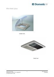
Installation <strong>instructions</strong> of the HEKI 3plus rooflightbefore installing the HEKI 3plus rooflight, please read carefully the <strong>installation</strong> <strong>instructions</strong>.1. Prerequisite for a correct <strong>installation</strong> of the HEKI 3plus rooflight is a flat inner andouter surface of the roof which are collateral (HEKI 3plus rooflight cannot be installedon a vertical surface)2. The area where the rooflight is to be installed has to be selected in such a way, thatthe function of adjacent components, cables, fitted cupboards in the vehicle interior,roof railings or other reinforcing components is not impaired in any way.(follow theguidelines of the vehicle manufacturer)3. The <strong>installation</strong> is possible either transversally (hinged side in front in the direction oftravel) or longitudinally (hinged side either left of right relative to the direction oftravel).4. To avoid damage to the roof wall, the cut-out must be sturdy (for example reinforcedwith wooden or tubular frames - not included in the package)5. We recommend the <strong>installation</strong> of the Seitz spoiler. Without the spoiler, the maximumspeed of 130km/h should not be exceeded, otherwise, depending on the constructionof the vehicle or the positioning of the rooflight, wind noise or material fatigue couldarise.6. The HEKI 3plus rooflight is ideal for a roof thickness between 25 and 60 mm.7. Check the roof thickness of your vehicle. In the package are included 16 mountingblocks and 16 screws (size 4x25 for a roof thickness of 25-32mm). (For a roofthickness over 32mm up to a maximum of 60mm, the corresponding, commerciallyavailable <strong>installation</strong> set must be used.)8. For the illumination of the HEKI 3plus rooflight, a 12 Volt power supply, which mustbe secured by a fuse of at least 10 Amperes, should be available in the vehicle in themiddle of one of the two long sides. Electrical connections are to be carried out onlyby trained personnel.9. Installation steps9.1 Determine location of cut-out9.2 Execute the cut-out9.3 Reinforce and check cut-out9.4 Install HEKI 3plus outer frame9.5 Connect HEKI 3plus inner frame illumination9.6 Install HEKI 3plus inner frame9.1 Determine the location of the cut-outDetermine the location of the HEKI 3plus on thevehicle taking into account the above-mentionedconditions.Mark the cut-out using the template (printed onthe packaging)(photo 9.1.1) according to theindications shown in photo 9.1.2.The installed HEKI 3plus rooflight should have aclearance of around 1-2 mm all around.9.1.1
ARadius = 65 mmBAusschnitt9.1.2A = 960 mmB = 655 mm9.1.29.2 Execute the cut-out9.2.1 In order to avoid scratches on the roofsurface, the perimeter should be coveredwith sticky tape before the cutting or millcuttingbeginsExecute the cut-out using a jig saw or arouting machine (photo 9.2.1)9.2.19.3 Reinforce and check the cut-out9.3.1 Remove insulating material betweenthe roof's outer surface and the inner liningfor a depth of about 10-30 mm all around theperimeter. (Depth depends on the reinforcingframes to be introduced in the next step -photo 9.3.2)(Photo 9.3.1)9.3.19.3.2 Insert reinforcing frames (metal,plastic, wood, etc.)Tip: This "reinforcing frame" is needed inorder to avoid permanently the insulatingmaterial being compressed.9.3.2
9.3.3 Should the illumination be connected, a12V supply is to be led out of the cut outperimeter to the long side where the crank is.9.3.39.3.4 To check the cut-out, place the outerframe on top of it to check the exact positionbefore applying the sealant. (A clearance of1-2 mm all around the perimeter between thecut-out and the outer frame is necessary.Photo 9.3.4)9.3.49.4 Install the outer frame9.4.1 Clean the roof surface where thesealant is to be applied (Always follow the<strong>instructions</strong> of the sealant supplier)(Photo9.4.1).9.4.19.4.2 Apply a butyl based permanentlyelastic sealant (available in cartridges or as aband) uniformly all around Photo 9.4.2)Place the outer frame in the cut-out (payattention to the 12V supply) and push gentlyagainst the roof so that the sealant isdistributed. (Always follow the <strong>instructions</strong> ofthe sealant supplier!)9.4.2
9.4.3. For a different roof thickness, the following mounting kits are needed:Wall thickness Colour: mounting block Screw Mounting kit25 - 32 mm grey Ø4 x25 mm in accessory package incl.32 - 39 mm black Ø4 x32 mm part no.134839 - 46 mm yellow Ø4 x40 mm part no.134946 - 53 mm blue Ø4 x46 mm part no.135053 - 60 mm red Ø4 x52 mm part no.13519.4.39.4.4 Insert the 16 mounting blocks all theway in and screw lightly (use the bigger holein the mounting blocks)(Photo 9.4.4)It is sufficient to tighten the screwsgently. (torque about 1.5 Nm)Check visually whether the sealant lies allaround the roof surface. (When required,tighten the mounting blocks uniformly afterabout 10-30 minutes – torque about 1.5 Nm)9.4.49.4.49.5 Connect inner frame illumination(optional)9.5.19.5.1.There is the facility to connect theillumination in the long side of the innerframe. In this case the tin clip should beremoved from the short side and inserted inthe appropriate housing in the longer side.(Photo 9.5.1) The cables are to be placed inreverse order and fixed in position.9.6 Install the inner frame9.6.1 Install the drive pinion according to thecorresponding roof thickness (see also table9.4.3)9.6.1
9.6.2 The pre-assembled crank is to remainin the closed position when the inner frameis joined to the outer one, otherwise the ratiobetween the crank and the drive hexagonwill be incorrect.9.6.29.6.3 Screw the inner frame to the outerframe. In this case the smaller holes in themounting blocks are to be used (screws2.15x12).It is sufficient to tighten the screwsgently!9.6.39.6.4 Check whether the blinds and fly-netsfunction properly! If they do not slidesmoothly, loosen slightly the screws of theinner frame.9.6.49.6.5 The connection for the two bulbs takesplace throught the clips, in which a separateswitching of the two bulbs is possible whenthe electro-technical prerequisites of thevehicle are given. (Electrical connections areto be carried out only by trained personnel).Follow the safety <strong>instructions</strong>!Beleuchtung = Lightning9.6.59.6.5
9.6.6 Snap the ventilation grilles and thecovers into position (a click should beaudible)9.6.69.6.7 Remove the protective PE foil from theinner and outer surfaces of the acrylic dome.9.6.710. Safety <strong>instructions</strong>- Attention! Before starting switch off the power supply.- The electrical connections are to be carried out only by trained personnel.- Utilise only the delivered parts.- Make sure that the wires are not damaged during the <strong>installation</strong>.- The light cannot be dimmed.- All 12V connections are to be fixed firmly.- Before the bulbs are switched on, make sure that they are firmly in place.- Defective bulbs can be replaced only by bulbs of identical build, power and voltage.- The manufacturer accepts no liability for injuries or damage caused by an inappropriateuse of the lights.- Follow the operating <strong>instructions</strong> as well.- No liability is assumed for incorrect <strong>installation</strong>!- The HEKI 3plus rooflight is not to be installed in a vertical surface!- Registration in vehicle's log book should be carried out when the vehicle's height and/ortotal weight is changed.