P28 and P128 Series Lube Oil Controls with - System Control ...
P28 and P128 Series Lube Oil Controls with - System Control ...
P28 and P128 Series Lube Oil Controls with - System Control ...

You also want an ePaper? Increase the reach of your titles
YUMPU automatically turns print PDFs into web optimized ePapers that Google loves.
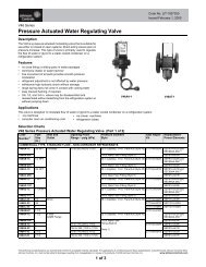
Master Catalog 125Pressure <strong><strong>Control</strong>s</strong> Section PProduct/Technical Bulletin <strong>P28</strong>Issue Date 0498<strong>P28</strong> <strong>and</strong> <strong>P128</strong> <strong>Series</strong> <strong>Lube</strong> <strong>Oil</strong> <strong><strong>Control</strong>s</strong><strong>with</strong> Built-in Time Delay RelayThe <strong>P28</strong> <strong>and</strong> <strong>P128</strong> <strong>Series</strong> <strong>Lube</strong> <strong>Oil</strong> <strong><strong>Control</strong>s</strong> providedependable <strong>and</strong> economical oil pressure cut-out forpressure-lubricated refrigeration compressors. Thefield-adjustable pressure differential of these controlsprovides compressor operation according to themanufacturer’s specifications. The <strong>P28</strong> <strong>and</strong> <strong>P128</strong>controls operate by measuring the net lube oilpressure <strong>and</strong> de-energizing the compressor if thepressure falls below the differential setpoint.Manual or automatic reset models are available <strong>with</strong>factory set <strong>and</strong> sealed time delays of 30, 45, 60, 90,or 120 seconds (all time delays may not be availableon all models). The <strong>P128</strong> is the same control as the<strong>P28</strong> but <strong>with</strong> 1/4 inch male flare pressure connections.Figure 1: <strong>P128</strong>AAFeatures <strong>and</strong> Benefits❑ Built-in Time Delay Relay<strong>with</strong> Ambient Compensation❑ Trip-free Manual Reset❑ Replaceable Time DelayRelay Assembly❑ Available <strong>with</strong> Runlight <strong>and</strong>Alarm TerminalsMinimizes timing fluctuations due to temperaturevariationsProvides manual reset that cannot be overriddenby pressing <strong>and</strong> holding the reset buttonAllows easy field replacement of the time delayrelay <strong>and</strong> terminal boardAllows the control to be wired for normal oilpressure runlight signals <strong>and</strong> shutdown alarmcircuits for remote monitoring of oil pressurestatus© 1998 Johnson <strong><strong>Control</strong>s</strong>, Inc. 1Part No. 24-7664-605, Rev. ACode No. LIT-125420
I ntroduction!WARNING: Personal injury hazard. All<strong>P28</strong> <strong>and</strong> <strong>P128</strong> controls aredesigned as lubricationprotection controls. Failure ofthe <strong>P28</strong> or <strong>P128</strong> could allowthe refrigeration compressorto be damaged in a way thatmay not be apparent uponvisual inspection. Followproper procedures <strong>and</strong> thecompressor manufacturer’sinstructions, as well as anywarning signs on or aroundthe equipment, whendischarging <strong>and</strong>disassembling thecompressor.Environmental damagehazard. If leakage of sensedmedia (such as refrigerant oroil) can be harmful to theenvironment, or hazardous inany way, user must providefor proper containment.The <strong>P28</strong> <strong>and</strong> <strong>P128</strong> controls measure the net oilpressure available to circulate oil throughout apressure-lubricated refrigeration system. The net oilpressure is the difference between the oil pressureat the pump discharge <strong>and</strong> the refrigerant pressurein the compressor crankcase.Example: If the oil pressure pump discharge readingis 90 psi (621 kPa) <strong>and</strong> the crankcasepressure is 70 psi (483 kPa), the net oilpressure is 20 psi (138 kPa).The <strong>P28</strong> <strong>and</strong> <strong>P128</strong> have a built-in time delay relay.This relay allows the oil pressure to build up for thetime delay period before the compressor trips. Thisalso prevents nuisance lockouts due to intermittentloss of oil pressure. The time delay relay is a“trip free” device. The manual reset cannot beoverridden by pressing <strong>and</strong> holding the reset button.Manual reset models are available <strong>with</strong> time delaysof 30, 45, 60, 90, or 120 seconds. Automatic resetmodels are available <strong>with</strong> a 90-second time delay.The time delay relay is compensated to minimize theeffect of ambient temperature variations. However,the time delay relay will be affected by voltagevariations.DimensionsFigure 2: <strong>P28</strong> or <strong>P128</strong> Dimensions (in./mm)O perationWhen the compressor starts, the timer is energizedbecause the net oil pressure of the system is zero.During normal operation, the net oil pressure shouldbuild up to the pressure switch’s cut-out setting(scale setting) plus the switch differential (3 to 5 psi[21 to 34 kPa]) <strong>with</strong>in the required time delay,causing the time delay relay to de-energize.If the net oil pressure does not rise to the cut-outpressure setting plus the switch differential <strong>with</strong>in therequired time delay, the time delay relay trips <strong>and</strong>stops the compressor.If the net oil pressure drops below the cut-outpressure setting during the compressor’s run cycle,the time delay relay energizes. If the net oilpressure returns <strong>with</strong>in the time delay, the timedelay relay de-energizes <strong>and</strong> the compressorcontinues to operate normally. If the net oil pressuredoes not return <strong>with</strong>in the time delay, the controlshuts down <strong>and</strong> locks out the compressor.2 P—<strong>P28</strong> <strong>and</strong> <strong>P128</strong> <strong>Series</strong> <strong>Lube</strong> <strong>Oil</strong> <strong><strong>Control</strong>s</strong> <strong>with</strong> Built-in Time Delay Relay Product/Technical Bulletin
Example: Net oil pressure (oil pump pressure minuscrankcase pressure) required to thebearings is 9 psi (62 kPa). The controlscale setting should be 9 psi (62 kPa).The switch differential is 5 psi (34 kPa).Upon initial start of the compressor, thetime delay relay energizes. If the net oilpressure does not build up to 14 psi(97 kPa), or the scale setting (9 psi) plusthe switch differential (5 psi), during thetime delay, the control breaks the circuit tothe compressor. If the pressure of 14 psi(97 kPa) is reached during the time delay,the time delay relay de-energizes <strong>and</strong> thecompressor continues to operatenormally.I nstallationMounting!CAUTION: Equipment damage hazard.●●●A <strong>P28</strong>AN or <strong>P28</strong>DN control used forammonia service must be mountedseparately from the electrical cabinet.An ammonia leak could damage theelectrical circuitry.Do not use Johnson <strong><strong>Control</strong>s</strong>/PennEcosafe® hose tubing in applications<strong>with</strong> ammonia or other corrosiverefrigerants. Corrosion could causetube breakage <strong>and</strong> refrigerantleakage.Use only the mounting screwssupplied <strong>with</strong> the control. Damage tointernal components may occur ifother screws are used.The <strong>P28</strong> <strong>and</strong> <strong>P128</strong> controls are not positionsensitive <strong>and</strong> can be mounted in any position.Use the two mounting screw holes located on theback of the control case to mount the control directlyto a wall or panel board. Mount the control so thatthe pressure connections on the bellows are abovethe crankcase liquid level of the equipment beingcontrolled.Note: When mounting the control to acompressor is required, a mounting bracket(Part No. 271-51) is available.Pressure Connections!CAUTION: Equipment damage hazard.●●●●Avoid sharp bends or kinks in thecapillary or tubing to avoid damage tothe capillary.Coil <strong>and</strong> secure excess capillary ortubing. Because harmonic vibrationcan break the capillary or tubing,some slack must be provided.Do not allow the capillary or tubing torub against metal surfaces wherefriction can cause damage.When using a control <strong>with</strong>1/4 in. / 6.4 mm tubing, a pulsationdamper must be used. Pulsation cancause excessive wear <strong>and</strong> damagethe control.1. Purge all tubing <strong>and</strong> lines before connecting thepressure control.2. Connect the oil pressure line pump discharge tothe pressure connector labeled “OIL.”3. Connect the crankcase pressure line to thepressure connector labeled “LOW.”4. Coil <strong>and</strong> secure excess capillary or tubing toavoid vibration.Wiring●●●!WARNING: Shock hazard. Disconnectall power supplies beforemaking wiring connections toavoid electrical shock ordamage to the equipment.Make all wiring connections using copperconductors only.Wire in accordance <strong>with</strong> National Electric Code<strong>and</strong> local regulations. For maximum electricalrating of the control, see the label inside thecontrol cover.Use the terminal screws furnished (8-32 x 1/4 in.binder head). Substitution of other screws maycause faulty connections.See Figures 3 through 10 for typical wiring diagramsor refer to the compressor manufacturer’sspecifications.P—<strong>P28</strong> <strong>and</strong> <strong>P128</strong> <strong>Series</strong> <strong>Lube</strong> <strong>Oil</strong> <strong><strong>Control</strong>s</strong> <strong>with</strong> Built-in Time Delay Relay Product/Technical Bulletin 3
When the <strong>P28</strong> or <strong>P128</strong> control is supplied <strong>with</strong> aTerminal 3, it may be wired to operate a runlight forindicating when there is sufficient net oil pressure.When the control is supplied <strong>with</strong> a Terminal A, itcan be wired to operate a shutdown alarm or signalfor indicating when the compressor has tripped.For applications using a 208V control circuit, it issuggested that one leg of the 208V circuit <strong>and</strong> aneutral or ground wire be used as a 120V source topower the time delay relay.When a <strong>P28</strong> or <strong>P128</strong> is installed on a 440 or 550VAC system, use an external step-down transformerto provide either 120 or 240V to the pilot <strong>and</strong> timedelay relay circuits. The transformer must be ofsufficient volt ampere capacity to operate the motorstarter <strong>and</strong> the time delay relay. Table 1 presentsthe power requirements for the <strong>P28</strong> or <strong>P128</strong> timedelay relay. Table 2 presents the electrical ratings.Table 1: Electrical Power Required forTime Delay RelayVoltageTiming inSeconds12, 24, or 120V 240V30, 45, 60, 90, or 120 15 VA 30 VATable 2: Electrical Ratings--Pilot DutyTime Delay RelayCircuitPilot Circuit Alarm Circuit* Crankcase Heater**(Terminal 1)Runlight**(Terminal 3)120/240 VAC 750 VA, 120/240 VAC 10W Tungsten, 120/240 VAC 10 Ampere, 120 VAC5 Ampere, 240 VAC24 VAC/VDC12 VAC/VDC125 VA, 24 VAC57.5 VA, 24 VDC* Must be the same voltage as the pilot circuit.** Must be the same voltage as the time delay relay circuit.125 VA, 24 VAC57.5 VA, 24 VDC10W Tungsten-- 10W TungstenLow 120/240 Models Low32401LPC 2 PC 1 TD 2 TD 12MHA120DR<strong>Oil</strong><strong>Oil</strong>Low Voltage Models3PC 21PC 1 TD 2LTD 12HMA24**12 volt also available.PC 1- Pressure actuated contacts. Open on increase in pressure difference between oil <strong>and</strong> low pressure conntectors. Makes<strong>and</strong> breaks time delay heater circuit.PC 2- Contacts close simultaneously when PC 1 contacts open (runlight circuit).TD 1- Time delay relay. Contacts open after time delay interval if pressure dfference between oil <strong>and</strong> low pressure connectorsis not established or maintained.TD 2- Contacts close simultaneously when TD 1 contacts open (alarm circuit).DR - Voltage dropping resistor used in dual voltage models.H - Heater for time delay relay.Connect Terminals L <strong>and</strong> M as a single pole switch.Connect Terminals 2 <strong>and</strong> 240 or 120 to energize circuit only when motor starter is closed.Figure 3: <strong>P28</strong> or <strong>P128</strong> Internal Wiring Circuit, Showing Alarm Circuit <strong>and</strong> Runlight Terminals4 P—<strong>P28</strong> <strong>and</strong> <strong>P128</strong> <strong>Series</strong> <strong>Lube</strong> <strong>Oil</strong> <strong><strong>Control</strong>s</strong> <strong>with</strong> Built-in Time Delay Relay Product/Technical Bulletin
Additional controls in this line only.240V 3-phaseL 1L 2L 3Ground120 or 240VSupplyHotAny VoltageC 2 L1 L 2L 3CrankcaseHeaterWhen Used*12LMA240120<strong>P28</strong> or <strong>P128</strong>Operating<strong>Control</strong>T 1 T 2T 3MotorCrankcaseHeaterWhen Used*Alarmif Used312 *Runlightif Used240LMA120<strong>P28</strong> or <strong>P128</strong>240 or120VOperating<strong>Control</strong>C 3C 4T 1T 2T 3MotorAdditional controlsin this line only.*Crankcase heater cannot be cycled <strong>with</strong> this hookup. See Figure 5.Figure 4: <strong>P28</strong> or <strong>P128</strong> Used on a 240V <strong>System</strong> <strong>with</strong>240V Magnetic Starter Coil*When crankcase heater is used, disconnect jumper from 2 to M<strong>and</strong> reconnect from 2 to L.Figure 6: <strong>P28</strong> or <strong>P128</strong> Where Separate Supply isProvided for <strong>Control</strong> Circuit (Jumper between2 <strong>and</strong> M [or L] must be field installed.)CrankcaseHeaterWhen Used*Alarmif UsedAdditional controls in this line only.Runlightif Used24031 L2*MA120<strong>P28</strong> or <strong>P128</strong>Operating<strong>Control</strong>240V 3-phaseL 1 L 2 L 3T 1 T 2 T 3Motor*When crankcase heater is used, disconnect jumper from 2 to M<strong>and</strong> reconnect from 2 to L.Figure 5: <strong>P28</strong> or <strong>P128</strong> Wired for 3-wire <strong>Control</strong>(Jumper between 2 <strong>and</strong> M [or L] must be fieldinstalled.)CrankcaseHeaterWhen Used*Alarmif Used240VRunlightif Used2403L12 * MA120<strong>P28</strong> or <strong>P128</strong>Operating<strong>Control</strong>440V440V3-phaseC 2L 1 L 2 L 3T 1 T 2 T 3MotorAdditional controlsin this line only.*When crankcase heater is used, disconnect jumper 2 to M<strong>and</strong> reconnect 2 to L. Also, make sure that control circuittransformer has sufficient output for additional load.Figure 7: <strong>P28</strong> or <strong>P128</strong> Wired for 440V Supply<strong>and</strong> 240V Magnetic Start Coil (Also for 550VUsing Proper Transformer) (Jumper between2 <strong>and</strong> M [or L] must be field installed.)C 3P—<strong>P28</strong> <strong>and</strong> <strong>P128</strong> <strong>Series</strong> <strong>Lube</strong> <strong>Oil</strong> <strong><strong>Control</strong>s</strong> <strong>with</strong> Built-in Time Delay Relay Product/Technical Bulletin 5
CrankcaseHeaterWhen Used*Alarmif UsedRunlightif Used2403L12 * MA120<strong>P28</strong> or <strong>P128</strong>StartStopAdditional controlsin this line only.240V3-phaseL 1L 2L 3C 2C 3T 1T 2T 3Motor*When crankcase heater is used, disconnect jumper from 2 to M<strong>and</strong> reconnect 2 to L.Figure 8: <strong>P28</strong> or <strong>P128</strong> Where Manual “Start-Stop”Pushbutton Station is Used (Jumper between2 <strong>and</strong> M [or L] must be field installed.)Alarmif Used312LMA24*<strong>P28</strong> or <strong>P128</strong>TransformerStarter CoilOperating<strong>Control</strong>*12 volt also available.240V3-phaseL 1 L 2 L 3T 1 T 2 T 3MotorAdditional controlsin this line only.Figure 9: <strong>P28</strong> or <strong>P128</strong> Where 24V <strong>Control</strong> CircuitPower is from a Step-down Transformer (Jumperbetween 2 <strong>and</strong> M must be field installed.)Low<strong>Oil</strong>P74AACompressorMotorLow<strong>Oil</strong><strong>P28</strong>/<strong>P128</strong>1 240L2MJunction BoxOperating<strong>Control</strong>240 VL 1L 2 L 3T 1T 2T 3Note: This system would provide shutdown on lowlube oil pressure in either of two compressorsoperated by the common motor.Figure 10: <strong>P28</strong> or <strong>P128</strong> <strong>and</strong> P74AA Wired for an<strong>Oil</strong> Pressure <strong>Control</strong> <strong>System</strong> Where One MotorOperates Two CompressorsAdjustmentsThe <strong>P28</strong> <strong>and</strong> <strong>P128</strong> controls are shipped <strong>with</strong> a cut-outpressure differential of 9 psi (62 kPa). However, thecontrols can be adjusted according to the compressormanufacturer’s specifications.Note: When the controls are shipped as anaccessory to the compressor unit, time delay<strong>and</strong> cut-out pressure are set to manufacturer’sspecifications. Replacement controls shouldduplicate the manufacturer’s specifications.!CAUTION: Equipment damage hazard.To avoid damage to thecompressor, obtain thecompressor manufacturer’s netoil bearing pressurespecifications as soon aspossible. If necessary, reset thecut-out pressure difference to themanufacturer’s specifications.When the manufacturer’s specifications are notknown, proceed as follows to set the cut-out pressuredifferential:1. With the compressor running, read the oilpressure <strong>and</strong> the crankcase pressure.2. Subtract the crankcase pressure reading from theoil pressure pump discharge reading. This is thenet oil pressure to the bearings.3. Set the cut-out pointer 6 to 8 psi (41 to 55 kPa)below the established running net oil pressure <strong>with</strong>the Adjusting Disk using a st<strong>and</strong>ard screwdriver.6 P—<strong>P28</strong> <strong>and</strong> <strong>P128</strong> <strong>Series</strong> <strong>Lube</strong> <strong>Oil</strong> <strong><strong>Control</strong>s</strong> <strong>with</strong> Built-in Time Delay Relay Product/Technical Bulletin
To increase the cut-out pressure, turn theAdjusting Disk counterclockwise. To decrease,turn clockwise.To raise the pressure differential, turn theAdjusting Disk (see Figure 2) to the left whenviewing the front of the control. Turn the adjustingdisk to the right to lower the pressure differential.Test for ShutdownImmediately after installing, <strong>and</strong> at regular intervalsthereafter, the time delay relay should be tested toverify that all circuits are operating correctly.!WARNING: Shock hazard. Disconnectpower from the control beforetesting for shutdown to avoidelectrical shock or damage tothe equipment.To test for shutdown:1. Remove power from the control <strong>and</strong> remove thecontrol cover.2. Connect a jumper between Terminals 1 <strong>and</strong> 2.See Figure 3 for terminal locations.Note: If the control is mounted on a condensingunit where air from auxiliary equipment(blowers or fans) may strike the control,the control cover should be replacedbefore proceeding to Step 3.3. Apply power to start the compressor. The timedelay relay should trip after the time interval <strong>and</strong>stop the compressor.4. Remove power from the control <strong>and</strong> remove thejumper between Terminals 1 <strong>and</strong> 2.5. Replace the cover on the control <strong>and</strong> apply power.6. Manually reset the time delay relay if required.Checkout ProcedureBefore leaving the installation, observe at leastthree complete operating cycles to be sure that allcomponents are functioning correctly.Fungus ProofingFungus proofing can be supplied at extra cost whenspecified. Conforms to government specificationsMIL-V-173A.Repairs <strong>and</strong> ReplacementField repairs must not be made, except forreplacement of the time delay relay assembly. For areplacement control or time delay relay assembly,contact the nearest Johnson <strong><strong>Control</strong>s</strong> representativeor Refrigeration Application Engineering at 414-274-5535.Table 3: Replacement Time Delay Relay AssembliesPart Number Voltage Reset Type Timing in Seconds Alarm CircuitRLY13A-600R 120/240 VAC Manual 60 NoRLY13A-602R 120/240 VAC Manual 90 NoRLY13A-603R 120/240 VAC Manual 90 YesRLY13A-608R 120/240 VAC Automatic 90 NoRLY13A-609R 24 VAC/VDC Manual 120 NoRLY13A-610R 120/240 VAC Manual 30 NoRLY13A-616R 120/240 VAC Manual 120 NoRLY13A-617R 120/240 VAC Manual 45 NoP—<strong>P28</strong> <strong>and</strong> <strong>P128</strong> <strong>Series</strong> <strong>Lube</strong> <strong>Oil</strong> <strong><strong>Control</strong>s</strong> <strong>with</strong> Built-in Time Delay Relay Product/Technical Bulletin 7
Ordering InformationTable 4: Ordering Information<strong>Series</strong> PartNumberPressureConnections*<strong>P28</strong>AA Style 13, Style 5,or Style 15Reset Type Refrigerant Time DelayRelay VoltageManualNon-corrosiveAll-range<strong>P128</strong>AA Style 5 Manual Non-corrosiveAll-rangeAlarmTerminalRunlightTerminal120/240 VAC No No120/240 VAC No No<strong>P28</strong>AN Style 15 Manual Ammonia 120/240 VAC No No<strong>P28</strong>DA Style 13 Manual Non-corrosiveAll-range120/240 VAC Yes Yes<strong>P28</strong>DN Style 15 Manual Ammonia 120/240 VAC Yes Yes<strong>P28</strong>GA Style 13 Automatic Non-corrosiveAll-range<strong>P28</strong>NA Style 13 or Style 5 Manual Non-corrosiveAll-range<strong>P28</strong>PA Style 5 Manual Non-corrosiveAll-range120/240 VAC No No24 VAC/VDC No No24 VAC/VDC No No* Style 5 connections are 1/4 in. / 6.4 mm SAE male flare connectors (no capillary tubing). Style 13 connections are 36 in. / 914 mmcapillary tubing <strong>and</strong> 1/4 in. / 6.4 mm flare nut. Style 15 connections are 1/4 in. / 6.4 mm female National Pipe Thread connectors.S pecifications Product <strong>P28</strong> <strong>and</strong> <strong>P128</strong> <strong>Series</strong> <strong>Lube</strong> <strong>Oil</strong> <strong><strong>Control</strong>s</strong> <strong>with</strong> Built-in Time Delay RelayPower Requirements See Tables 1 <strong>and</strong> 2.Pressure SpecificationsPressure Switch UnitsAdjustable Cut-out Pressure Difference: 8 to 70 psi (55 to 483 kPa)*Maximum Differential:70 psi (483 kPa)Maximum Working Pressure:250 psig (1724 kPa) on the high sideMaximum Overpressure:325 psi (2240 kPa) oil <strong>and</strong> low side pressure*The time delay relay is de-energized 3 to 5 psi (21 to 34 kPa) above the cut-out scale setting.Enclosed Dust-protected PennswitchAmbient Operating Conditions 32 to 104°F / 0 to 40°CMaterial Case: 0.062 in. / 1.6 mm Galvanized SteelCover: 0.028 in. / 0.7 mm Cold Rolled Steel (plated <strong>and</strong> painted)Mounting Flat Surface or <strong>with</strong> a Universal Mounting Bracket (Part No. 271-51)Wiring TerminalAgency ListingsDimensions (H x W x D)Large 8-32 x 1/4 in. Binder Head ScrewsUL Guide No. SDFY; File SA516**CSA Class No. 1222 01; File LR948****Most models. Contact Johnson <strong><strong>Control</strong>s</strong> for a complete listing.5.66 x 5.32 x 2.09 in. / 144 x 135 x 53 mmShipping Weight 3.0 lb / 1.36 kgThe performance specifications are nominal <strong>and</strong> conform to acceptable industry st<strong>and</strong>ards. For application at conditions beyond these specifications,consult the local Johnson <strong><strong>Control</strong>s</strong> Refrigeration Application Engineering at (414) 274-5535. Johnson <strong><strong>Control</strong>s</strong>, Inc. shall not be liable for damagesresulting from misapplication or misuse of its products.<strong><strong>Control</strong>s</strong> Group FAN 125507 E. Michigan Street Master CatalogP.O. Box 423Milwaukee, WI 532018 P—<strong>P28</strong> <strong>and</strong> <strong>P128</strong> <strong>Series</strong> <strong>Lube</strong> <strong>Oil</strong> <strong><strong>Control</strong>s</strong> <strong>with</strong> Built-in Time Delay Relay Product/Technical Bulletin