Proceedings of 2010 LWR Fuel Performance/TopFuel/WRFPMOrlando, Florida, USA, September 26-29, 2010Paper 097III. OPEN VALVE TEST EVENT DESCRIPTIONTo demonstr<strong>at</strong>e the applic<strong>at</strong>ion of the various <strong>PCI</strong>evalu<strong>at</strong>ion methods to actual oper<strong>at</strong>ing d<strong>at</strong>a, a specificevent from an oper<strong>at</strong>ing <strong>PWR</strong> in Southern Nuclear's fleetwas selected. The event is called an open valve test. Thetest itself should result in fairly mild changes in LHGRvalues. However, upon completion of the test in the actualplant, coolant off-gas activity increased indic<strong>at</strong>ing fuelfailure. The analysis was motiv<strong>at</strong>ed by the need toelimin<strong>at</strong>e <strong>PCI</strong> as a possible cause.In an open valve test the reactor core inlet coolanttemper<strong>at</strong>ure is reduced to facilit<strong>at</strong>e testing on thesecondary side. The temper<strong>at</strong>ure reduction is mild, on theorder of a few degrees.This particular event was conducted near BOC <strong>at</strong> fullreactor power (HFP). The MTC for the core <strong>at</strong> thiscondition was slightly neg<strong>at</strong>ive in value (meaning astemper<strong>at</strong>ure decreases positive reactivity is inserted). Inorder for the reactor to remain critical this positivereactivity insertion must be balanced with the insertion ofneg<strong>at</strong>ive reactivity by partially inserting the lead controlbank. <strong>During</strong> this event, the lead bank was partiallyinserted approxim<strong>at</strong>ely 10% into the core.Once the testing on the secondary side is complete, thelead control bank is withdrawn to a full out position as theinlet coolant temper<strong>at</strong>ure is slowly raised back to nominal.<strong>During</strong> this movement of the lead control bank <strong>at</strong> HFPLHGR is redistributed axially and radially within the core.Since <strong>PCI</strong> is dependent on changes in LHGR vs. time, thisevent was chosen to apply the various <strong>PCI</strong> methodspreviously discussed.IV. ANALYSIS MODELS OF SPECIFIC OPERATINGEVENTS DESCRIPTIONIn order to assess <strong>PCI</strong> during oper<strong>at</strong>ing events, severalcalcul<strong>at</strong>ional components are necessary: an accur<strong>at</strong>e threedimensional,cycle-specific core neutronic model, detailedcore follow d<strong>at</strong>a for the actual transients, an accur<strong>at</strong>ethermo-mechanical fuel performance code, a systemcoupling these models together, and a d<strong>at</strong>a managementsystem to digest and resolve all the d<strong>at</strong>a points into asuccinct summary for the events. This section describesthese analysis models.IV. A. CMS Model DescriptionA cycle-specific CMS neutronics model, comprised of<strong>Studsvik</strong>’s CASMO 1 and SIMULATE 2 codes, has beenused for several cycles <strong>at</strong> Southern Nuclear for fuel vendoroversight, oper<strong>at</strong>ional support, and oper<strong>at</strong>or simul<strong>at</strong>ortraining. These models employ CASMO as the crosssectionl<strong>at</strong>tice code and SIMULATE as the steady-st<strong>at</strong>enodal simul<strong>at</strong>or.IV. B. CMSOps Model Description<strong>Studsvik</strong>’s CMSOps 3 was used to integr<strong>at</strong>e detailedplant oper<strong>at</strong>ional d<strong>at</strong>a during the events analyzed withinthis paper 4 . CMSOps manages the high-fidelity CMSneutronics model for reactivity management, including <strong>at</strong>hreshold based <strong>PCI</strong> assessment.CMSOps ensures the CMS core neutronics modelaccur<strong>at</strong>ely reflects the plant’s actual detailed oper<strong>at</strong>inghistory by autom<strong>at</strong>ing core follow. CMSOps reads plantmeasured signals on a minute-by-minute frequency anddetects any changes in the values of these signals. Basedon certain change criteria being met (e.g., changes inpower level, lead control bank position, inlet temper<strong>at</strong>urechange, etc.), CMSOps autom<strong>at</strong>ically activ<strong>at</strong>es executionand upd<strong>at</strong>ing of the cycle-specific SIMULATE model.CMSOps is built on a very efficient d<strong>at</strong>abase th<strong>at</strong>archives all of the measured signals and all calcul<strong>at</strong>edneutronic parameters, making it easy to assess <strong>PCI</strong> usingother techniques, such as the delta-kW/ft and the thresholdmodels.<strong>Studsvik</strong>, with assistance from Southern's engineers,implemented CMSOps for the plant in which the oper<strong>at</strong>ingevent (open valve test) was conducted. This event resultedin several SIMULATE calcul<strong>at</strong>ions over a small amount oftime (~8 hours), each of which produced detailed threedimensionalLHGR pin-maps.IV. C. ENIGMA Thermo-Mechanical FuelPerformance Model DescriptionThe UK N<strong>at</strong>ional Nuclear Labor<strong>at</strong>ory (NNL)particip<strong>at</strong>ed in the analysis by evalu<strong>at</strong>ing the CMS d<strong>at</strong>afrom the oper<strong>at</strong>ional event using their fuel performancecode, ENIGMA 5 .
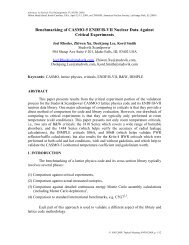
Proceedings of 2010 LWR Fuel Performance/TopFuel/WRFPMOrlando, Florida, USA, September 26-29, 2010Paper 097ENIGMA is a fully valid<strong>at</strong>ed fuel performance codeth<strong>at</strong> has been used for several definitive design andlicensing assessments for both UO2 and MOX fuel,including licensing UO2 and gadolinia-doped UO2 inSizewell B (the UK’s only <strong>PWR</strong>) and the Finnish LoviisaVVER-440 reactor, and mixed oxide (MOX) fuel in theSwiss Beznau-1 <strong>PWR</strong>. ENIGMA is also used in support ofMOX production in the Sellafield MOX Plant (SMP) andto perform feasibility studies for advanced fuel concepts.Recently NNL and <strong>Studsvik</strong> have coupled the CMScore neutronics model and ENIGMA’s fuel performanceanalysis capabilities, producing ONUS 6,7 to performthermo-mechanical analysis of every fuel pin in the core.Since CMSOps autom<strong>at</strong>ically gener<strong>at</strong>es CMS casesfor the entire oper<strong>at</strong>ional event, detailed LHGR's gener<strong>at</strong>edare available for every fuel pin and axial pin node in thecore. This d<strong>at</strong>a was coupled directly with ENIGMA toperform <strong>PCI</strong> evalu<strong>at</strong>ion for every pin in the core, using itsdetailed power history. ONUS is also then used to displaythe 3-D pin-by-pin d<strong>at</strong>a available following the analysis.V. <strong>PCI</strong> RESULTS FROM OPEN VALVE TESTThis event provided an opportunity to explore thevarious ways of monitoring <strong>PCI</strong> limits in order to mitig<strong>at</strong>e<strong>PCI</strong> viol<strong>at</strong>ions. The three various methods explainedpreviously are applied.Fig.3. presents a graphical result from ONUS(ENIGMA/CMS), of the normalized, axially integr<strong>at</strong>ed(radial) pin-by-pin LHGR <strong>at</strong> the point of deepest insertionof the lead control bank. The core loading p<strong>at</strong>tern is easilyrecognized as a contemporary low-leakage one.Fig.3. Rel<strong>at</strong>ive Power Density Distribution and LeadControl Bank Loc<strong>at</strong>ions during Event (Circles)Note also the loc<strong>at</strong>ions of the lead control bank, whichis partially inserted during the open valve test. Since theloc<strong>at</strong>ions are in rel<strong>at</strong>ively high-powered regions, theconcern of <strong>PCI</strong> during the event is warranted.V. A. Delta-kW/ft Results for Open Valve TestUsing d<strong>at</strong>a from the open valve test event, the deltakW/ftanalysis was applied to assess margin to <strong>PCI</strong> limit.This analysis calcul<strong>at</strong>ed delta-kW/ft/hr, as compared to theimmedi<strong>at</strong>ely previous case, calcul<strong>at</strong>ed with d<strong>at</strong>a for everynode in the core, as shown in Fig. 4. and Fig. 5.Fig. 4. Nodal delta-kW/ft/hr during Open Valve Test vs.Exposure..