Soundcraft Guide to Mixing - Music
Soundcraft Guide to Mixing - Music
Soundcraft Guide to Mixing - Music
- No tags were found...

Create successful ePaper yourself
Turn your PDF publications into a flip-book with our unique Google optimized e-Paper software.
THE SOUNDCRAFTGUIDE TO MIXING<strong>Soundcraft</strong> Registered Community Trade Mark / RTM No. 000557827SOUNDCRAFTHARMAN INTERNATIONAL INDUSTRIES LTD.CRANBORNE HOUSE,CRANBORNE ROAD,POTTERS BAR,HERTS, EN6 3JN, UK.TEL: +44 (0)1707 665000FAX: +44 (0)1707 660742EMAIL: info@soundcraft.comSOUNDCRAFT USA1449 DONELSON PIKE,NASHVILLE TN 37217, USATEL: 1-615-360-0471FAX: 1-615-360-0273EMAIL: soundcraft-usa@harman.comwww.soundcraft.com<strong>Soundcraft</strong> reserves the right <strong>to</strong> improve or otherwise alter any information supplied in thisdocument or any other documentation supplied hereafter. E&OE 08/01Part No. ZL0439
THE SOUNDCRAFT GUIDE TO MIXING – CONTENTSCONTENTSSECTION 1: STARTING OUTA What does a Mixer do? 3B <strong>Guide</strong>lines in Choosing a Mixer. 3C The Controls - A Description. 3Mono Inputs, Stereo Inputs, Subgroups,the Master Section.D Signal Flow. 7SECTION 2: CONNECTINGEQUIPMENT TO YOUR MIXERA Input Devices. 8B Equipment requiring Inputs and Outputs. 9C Output Devices. 9SECTION 3:MIXING TECHNIQUESA Choosing the Right Microphone; 10Microphone types, Condenser, Dynamic,Electret. Different Polar Patterns.B Setting up a Basic Mix; 11Setting the Gain, Balancing Fader Levels,Balancing Output Levels.C Using the Mixer’s EQ; 12Fixed EQ. Using a sweep-mid equaliser.D Using Effects Units; 13The different types; Reverb, Delay, Echo,Chorus & Flanging, Pitch Shifters.Setting up an effects loop.Pre and post fade auxiliaries.E Using Signal Processors; 15The difference between signal processors and effects;Different types of signal processors; Graphic Equalisers,Parametric Equalisers, Gates, Expanders,Compressors/Limiters.Setting up a processor.F Creating a Foldback/Moni<strong>to</strong>r Mix. 16SECTION 4: PA MIXINGA Introduction, A Typical Live Performance; Microphones,Cables and Connections, Connecting External Effects andProcessors, Setting Up, Ringing Out: Nulling RoomAcoustics, Setting the Mix, Avoiding Feedback. 17B Larger Performances; Medium Venues,Large Sized Venues. 20C Recording Live. 22SECTION 5:OTHER APPLICATIONSA Moni<strong>to</strong>r mixing. 23B Submixing. 24SECTION 6: IN THE STUDIOA Essentials and Ergonomics. 25B Tape Machines and Recording media. 25C The Console. 25D Simple Multitrack Recording. 26E Simple Multitrack Mixdown. 27F Using a Dedicated In-Line Console. 28G Recording Instruments and Voices; Vocals, Drums, ElectricGuitars, Acoustic Guitars, Bass Guitars, Keyboards. 28H Planning a Session. 30I Creating a Mix. 30J Balancing the Mix. 30SECTION 7:WIRING UP & CONNECTORSBalanced and Unbalanced Mic Inputs, Balanced andUnbalanced Line Inputs. 31Inserts, Ground Compensated Outputs, ImpedanceBalanced Outputs. 31SECTION 8: GLOSSARYAn A <strong>to</strong> Z <strong>to</strong> save your head! 322
STARTING OUTC. The Controls -A DescriptionDIRA. What does a Mixer do?No matter how sophisticated or expensive, all mixers carryout the same basic function - <strong>to</strong> blend and control thevolume of a number of input signals, add effects andprocessing where required and route the resulting mix <strong>to</strong>the appropriate destination, which could be poweramplifiers, the tracks of a recording device - or both. Amixer is the nerve centre of these sources, and therefore themost vital part of your audio system.B. <strong>Guide</strong>lines inChoosing a MixerAudio mixers come in many different sizes and at all pricelevels, so it’s little wonder that people are confused as <strong>to</strong>what type is actually needed for the job in hand. Howeverthere are several questions you can <strong>to</strong> ask yourself that willhelp you narrow your search <strong>to</strong> the most appropriatemodels.• What am I going <strong>to</strong> be using the mixer for - i.e.multitrack recording, live PA work or both?• What is my budget?• How many sound sources do I have? As a guideline yourmixer needs <strong>to</strong> have at least as many inputs as soundsources. If you are likely <strong>to</strong> be buying more equipment inthe future you should budget for extra inputs.• What particular mixer facilities must I have for myapplication? i.e. plenty of EQ, auxiliaries, or Direct Outsfor recording.• How portable does the mixer need <strong>to</strong> be?• Will I be doing any location work where there won’t beany mains power available?• Have I read the <strong>Soundcraft</strong> <strong>Guide</strong> <strong>to</strong> <strong>Mixing</strong> from cover<strong>to</strong> cover?Once you can answer these questions satisfac<strong>to</strong>rily youshould have a fairly accurate specification for the mixer youneed.This is where we get in<strong>to</strong> the nitty-gritty ofwhat controls and inputs/outputs you’ll findon a typical mixer. For this example, we’veused a Spirit SX . If you are alreadyfamiliar with what the controls on astandard mixer do, then it’s OK <strong>to</strong> skip <strong>to</strong>section 2. If you find a term particularlydifficult, further explanation can be foundin the Glossary (Section 8).MONO INPUTSA Mic InUse this "XLR" input <strong>to</strong> connect yourmicrophones or DI boxes.For Mic Input Wiring Explanations see section 7.BCLine InUse this connec<strong>to</strong>r for plugging in "LineLevel" instruments such as keyboards,samplers or drum machines. It can also beused <strong>to</strong> accept the returns from multitracktape machines and other recording media.The Line Input is not designed formicrophones and although it may be used,will not provide optimum performance withthem.For Line Input wiring explanations see section 7.Insert PointThis is used <strong>to</strong> connect external signalprocessors such as compressors or limiterswithin the input module. The Insert Pointallows externalMIC/LINEdevices <strong>to</strong> bePROCESSORplaced within the- COMPRESSOR Input Path - see- NOISE GATE- LIMITERFig. 1.1.INSERTEQ- EXPANDERFIG. 1.1See Section 2 and 3for more detail on how <strong>to</strong> use processors, andSection 7 for information on wiring.30 SENS20 40105050 -60dBu100Hz– 0 +3 36 69 912 1215 150 10– 0 +3 36 69 912 1215 15– 0 +3 36 69 912 1215 1500010101001 12 23 34 45 50NMIXSUBPFLMICLINEINSABCHFMIDLFAUX1PREAUX2POST/PREAUX3POSTPAN1050510152030∞SECTION 1: Starting Out83
SECTION 1: Starting Out4DEFGDirect OutThis allows you <strong>to</strong> send audio direct fromyour channel out <strong>to</strong> a multitrack taperecorder, or <strong>to</strong> an effects unit when the channelrequires its own special effect.See sections 2 and 6 for more details on connectionsand studio techniques.Gain Control (Input Sensitivity)Sets how much of the signal from themic or line inputs is fed <strong>to</strong> the channel.HPF (High Pass Filter)As the name suggests this switch cuts out thevery lowest frequencies of a sound whilstallowing the higher frequencies <strong>to</strong> “PassThrough”. It’s particularly useful in livesituations <strong>to</strong> reduce stage rumble or microphone‘popping’, which can produce a muddy mix,or <strong>to</strong> ‘clean-up’ male vocals and filter out lowfrequency hum. Some manufacturers mayalso use the term “low - cut” filter <strong>to</strong> describethe HPF. See Fig. 1.2.+20+15STAGE RUMBLEMIC “POPPING”FIG. 1.2+10+5 100HzHPFdB 0-3-5-10-15-2020 60 100 500 1k 5k 10kHzEQ SectionUsually the most closely scrutinised part ofany mixer, the equaliser section allows you <strong>to</strong>change the <strong>to</strong>ne of the sound on each input.An EQ is normally split in<strong>to</strong> “bands”, whichcontrol a range of frequencies, in a similarfashion <strong>to</strong> the treble and bass <strong>to</strong>ne controls onyour Hi-Fi. Indeed a simple “2 band” EQ islittle more than an input treble and bass control.The more bands an EQ has the moresophisticated it is. SX has a 3 band EQ, with aseparate control for the middle audiofrequencies. This control is also “swept” whichprovides even more sophistication. Simplydescribed, a sweep EQ allows you <strong>to</strong> choosethe exact frequency <strong>to</strong> cut and boost, ratherthan having it chosen for you, as on normal“fixed” controls.We will talk in more detail about EQ in section 3.DEFGHIKMJ30 SENS20 40105050 -60dBu100Hz– 0 +3 36 69 912 1215 150 10– 0 +3 36 69 912 1215 15– 0 +3 36 69 912 1215 1500010101001 12 23 34 45 50NMIXSUBLPFL8DIRMICLINEINSHFMIDLFAUX1PREAUX2POST/PREAUX3POSTPAN1050510152030∞FIG. 1.3H Auxiliary SectionTypically, these controls have two functions: First, <strong>to</strong>control the levels of effects such as reverb from externaleffects units that have been added <strong>to</strong> the input signal, andsecond <strong>to</strong> create separate musician’s "foldback" mixes inthe studio or on stage.How <strong>to</strong> use auxiliaries, connecting them <strong>to</strong> external equipmentand other applications are described in section 3.I Pan (Panoramic Control)This determines the position of the signal within thestereo mix image or may be used <strong>to</strong> route (send) the signal<strong>to</strong> particular GROUP outputs as selected by theROUTING SWITCHES (see below).J Solo (PFL and Solo in Place)The PFL solo switch allows you <strong>to</strong> moni<strong>to</strong>r an inputsignal independently of any other instruments that havebeen connected, which is useful for troubleshooting, orsetting an instrument’s Input Preamp Gain and EQsetting.Pre-Fade Listen (PFL) is a type of solo that allows you<strong>to</strong> moni<strong>to</strong>r your sound BEFORE THE FADER. In otherwords when you move the input fader in PFL mode thelevel will not change, nor will you hear any effects.Because effects and volume are not a distraction, PFL solois very useful for setting proper input preamp levels.Some <strong>Soundcraft</strong> mixers use SOLO IN PLACE, whichallows you <strong>to</strong> moni<strong>to</strong>r signals after the fader in their truestereo image, and with any effects that have been added.This type of Solo is less good for level setting, but moreuseful in mixdown situations for auditioning sounds.See section 3 - Setting Gain, for more information on using PFL.K Mute/Channel On-Off SwitchThis turns the channel on or off and is useful for isolatingthe channel when not in use or pre-setting channel levelswhich may not be needed until later, ie: theatre scenesettingor support acts/performers.L FaderThis determines the level of the input signal within themix and provides a visible indication of channel level.M RoutingBy selecting the routing switches the input signal is sent<strong>to</strong> a choice of the mixer’s outputs - typically the main mixouts or the group outputs. The switches are used inconjunction with the PAN control <strong>to</strong> route the signalproportionately <strong>to</strong> the left or the right side of the mixor <strong>to</strong> odd/even groups/subs if PAN is turned fully left orright.
SECTION 1: Starting OutTHE MASTER SECTIONNOPQRSMix OutputsMix outputs provide left and right level control of the finalstereo mix. Many consoles feature mix insert points <strong>to</strong>o,allowing the connection of signal processors across thewhole mix.Moni<strong>to</strong>r “Engineer’s” / Control Room OutputsThese let you listen <strong>to</strong> any solo, mix, submix from a group,or the 2 Track tape return via an external amplifier andspeakers, or the headphone socket.2 Track Tape ReturnsAllow you <strong>to</strong> connect the outputs of your cassette or DATplayer and listen back <strong>to</strong> your completed masterwork. Theymay also be used for playing pre-show music at a gig using2-Track <strong>to</strong> Mix switch (not shown in illustration).Aux MastersThese govern the overall output levels from the auxiliaryoutputs and therefore the amount of signal going <strong>to</strong> aneffects unit or a musician’s foldback mix.AFLAllows moni<strong>to</strong>ring of the actual signal leaving the AuxMasters.MetersNormally they show mix output levels. When any Solobut<strong>to</strong>n is pressed, the meters au<strong>to</strong>matically switch <strong>to</strong> showthe solo level. They provide visual indication of what’sgoing on in your mixer.VMore Information onCondenser Mics can befound in Section 3 - <strong>Mixing</strong>Techniques.Further detail on micwiring may be found inSection 7 - wiring.HeadphonesAllow you <strong>to</strong> listen <strong>to</strong>your mix withoutannoying yourneighbours or beingdistracted by ambientsounds.That’s it, the basic featuresof your average mixingconsole. If you found it alittle heavy going, don’tdespair: it does get easier!ULMIX INSERT48VSREF +4dBuPHONESQPOSTPRESUBTOMIX0MIXLRL000MONITORO1610630-3-6-9-12-16PFLPOWER54 63 7101010R2 81 90 10RLRAUX1AUX2AUX30NMONO SUMV2TKLEVELAFLAFLAFLMAXSUB54 63 72 81 90 102TKPFLAFLR54 63 72 81 90 10MONO SUM0P2TKPHONESLRTUStereo Returns (see Stereo Inputs earlier in this section)These allow signals from external equipment, such as effectsunits, <strong>to</strong> be returned <strong>to</strong> the mixer and routed <strong>to</strong> the stereoMix or Groups, without using up valuable input channels.+48v or Phan<strong>to</strong>m PowerSome microphones, known as condenser mics, requirebattery power <strong>to</strong> operate. Alternatively the power may beprovided by the console. This is known as ‘phan<strong>to</strong>m power’and runs at 48vDC. Simply press “Phan<strong>to</strong>m Power” andany condenser mics connected will operate without theneed for batteries.5101520253040∞L SUB R5101520253040∞5101520253040∞L MIX RCaution: DO NOT ACTIVATE A GLOBAL PHANTOMPOWER SWITCH IF AN UNBALANCED SIGNALSOURCES IS CONNECTED TO ANY MIC INPUT.Because of the voltage present on pins 2 and 3 of the XLRconnec<strong>to</strong>r, you will damage your microphone/signal source.Always refer <strong>to</strong> your Mixer’s User <strong>Guide</strong>.FIG. 1.56
D. Signal FlowMICLINENow the typical mixer features have been explained indetail it is important <strong>to</strong> understand how they form<strong>to</strong>gether. The route which a signal source takes through amixer is normally shown using one of two devices:a block diagram or a signal flow diagram.Both diagrams provide a ‘visual’ description of the keyelements of the mixing console. They allow you <strong>to</strong> identifywhich components are used in the audio path and help theengineer <strong>to</strong> “troubleshoot” when signal sources don’t appear<strong>to</strong> be doing what they should! In simple terms, they areelectronic maps.An example of a signal flow diagram is shown here. Thisis the most basic representation of console layout, showinga how a single sound source may pass through an inputstrip <strong>to</strong> the various other parts of the mixer.Block diagrams are slightly more complex, showing moredetail, electronic information, including the location ofresis<strong>to</strong>rs and capaci<strong>to</strong>rs, and the structure of the entireconsole including bussing: an example is shown on page37. Block diagrams also use a number of symbols <strong>to</strong>represent electronic elements. A few minutes spentunderstanding them some time during your journeythrough this booklet will most definitely pay-off in futuremixing projects.MICPREAMPHI PASSFILTERINSERTEQON/OFFSWITCHAUX PREAUX PREMASTERAUX PREOUTSECTION 1: Starting OutFADERAUX POSTAUX POSTMASTERAUX POSTOUTPANFIG. 1.6A Typical Signal Flow PathROUTINGSWITCHSUB GROUPFADERSUB GROUPOUTSUB GROUPTO MIXMIXFADERMIXOUTPUT7
SECTION 2: Connecting Equipment <strong>to</strong> your MixerCONNECTING EQUIPMENTTO YOUR MIXERAs we explained in the last section, it is the job of the mixer<strong>to</strong> accept the various signal sources, set the levels and routethose signals <strong>to</strong> the correct destination.We’ll now take a quick look at where <strong>to</strong> connect the‘peripheral’ equipment that you will be using with yourmixer. If you have already created your own set-upssuccessfully in the past, you should only need <strong>to</strong>skim this part.FIG. 2.1MIC ONGUITARAMPA. Input DevicesMicrophonesAll microphones should be connected via eachinput’s XLR connec<strong>to</strong>rs. Do not use line inputs.For more information on miking up individual instruments,refer <strong>to</strong> sections 4 and 6 - PA <strong>Mixing</strong> and In the Studio.Direct Injection Box (DI Box)• A DI Box allows you <strong>to</strong> connect a guitar or bass directly<strong>to</strong> the mixer’s input, rather than miking up theinstrument’s amp/speaker. This technique is oftenpreferred by musicians who require a “clean” sound.The best DI boxes are ACTIVE and require Phan<strong>to</strong>mPower like condenser microphones. They should beconnected <strong>to</strong> XLR mic inputs.NB: Although electric guitars and basses may be connected <strong>to</strong> amixer’s line inputs without danger, the results will be far fromideal, because the IMPEDANCE of these instruments willnot match up with typical line levels. Direct connectionusually leads <strong>to</strong> a weak sound.KEYBOARD, SYNTHESISER,DRUM MACHINE OR SUBMIXEREFFECTS UNITGRAPHIC EQGUITARVIADI BOXMIC ONDRUM KITPOWERSUPPLYVOCAL MICAux PostDIRECT OUTSTOMULTITRACKTAPEINPUTEFFECTS UNITDIR DIR DIR DIR DIR DIR DIR DIRMICLINEMICLINEINSINS1 2MICLINEINS3MICMICMICGRAPHICEQMICMICMICMAIN OUTPUTSLSUBR LSUBRLINE LINE LINE LINE LINE LINE LINE LINE LINELRINSINSINSINSINSINSINSINSINS4 5 6 7 8 9 10 11 12MICMICAUX 1 AUX 2 AUX 3MICLSTE-CRA-STE-BLSTE-DRLRMIX INSERT MONITOR MONO SUMLRLR2TKPHONESLRCOMPRESSOR/LIMITERKEYBOARD, SYNTHESISEROR SAMPLERPOWER AMPSURROUND/FILL/VOCALSPEAKERS(or frommono output)POWER AMPPASPEAKERSGRAPHIC EQPOWER AMPARTISTS FOLDBACKCASSETTE ORDAT PLAYBACKHEADPHONES>200R8
Electronic Line Output Devices• Keyboards, Drum Machines, CD Players, DATMachines, Wireless Mic Receivers, all provide line leveloutputs, and should all be connected straight in<strong>to</strong> theMixer’s Line Inputs. If some of your instruments areSTEREO connect their left and right outputs <strong>to</strong> a sparestereo input. Alternatively connect <strong>to</strong> an adjacent pair ofmono inputs and Pan the inputs hard left and right <strong>to</strong>create a stereo image.B. Equipment Requiring BothInputs and OutputsExternal effects unitsConnect the input of your effects unit marked "mono" <strong>to</strong>A POST FADER AUXILIARY OUTPUT. If you areuncertain, Post fader auxiliaries are coloured blue on<strong>Soundcraft</strong> mixers with the relevant channel aux potsusually marked "post". The left and right outputs from theeffects unit should be connected <strong>to</strong> a pair of stereo returns,or stereo inputs if stereo returns are not available. Ifintensive EQ is required, use a pair of Mono Inputs.Remember, the effects signal is no different from any otheraudio signal – it still requires an input <strong>to</strong> the mixer.See Section 3 <strong>Mixing</strong> Techniques or a detailed explanation of postfader auxiliaries.NB: YOU DO NOT HAVE TO CONNECT UP BOTH THELEFT AND RIGHT INPUTS OF YOUR EFFECTS UNITTO SEPARATE AUXs. Most units only require "pseudo-stereo"operation and will mimic a stereo reverb or effect inside beforeproviding a stereo output <strong>to</strong> the mixer’s returns.Signal ProcessorsConnect signal processors, such as compressors <strong>to</strong> the insertjack using a special insert ‘Y’ cable. This allows the signal <strong>to</strong>be sent and returned <strong>to</strong> the mixer using only oneconnec<strong>to</strong>r.Refer <strong>to</strong> section 7 for wiring information.It is also possible <strong>to</strong> connect the processor <strong>to</strong> the consolewithout using the insert jacks by connecting an instrumentdirect <strong>to</strong> the processor first. However, the advantage ofusing processors in the mix/group or channel inserts is thatany level changes made by the processor can be moni<strong>to</strong>redby the mixers meters.NB: A signal processor can be used in a channel <strong>to</strong> control one audiosource, across a group <strong>to</strong> control a number of audio sources oracross the entire mix.Tape machinesMultitrack machines are used for initial track-laying ineither studio or live recording situations.For more sophisticated work, a stand-alone machine offersbetter sound quality and greater versatility than a cassettemultitracker. The new generation of digital multitracks arealso very attractive, but analogue, open-reel multitracks arealso capable of professional sounding results. Aim for aminimum of eight tracks if your budget will allow.Mastering MachinesYour final mix should be recorded on the best qualitymachine that you can afford. A recording is only as good asthe weakest link in the chain, and a good cassette machineis fine for demos, but for more serious work, consider aDAT machine or perhaps a second hand, open-reel 2-track.C. Output DevicesAmps and Speakers (Moni<strong>to</strong>r and FOH)Studio Moni<strong>to</strong>ringA high-powered hi-fi amp of around 50 watts per channelis fine for home recording, but <strong>to</strong> ensure adequate headroomyou should consider a well-specified rack mount amp.Similarly, a pair of accurate hi-fi speakers will do the job,but for more serious work we would recommend purposedesignednearfield moni<strong>to</strong>rs. Always remember that nomatter how good the recording or performance, a poormoni<strong>to</strong>ring set-up will not allow you <strong>to</strong> make qualitativejudgements about the mix.HeadphonesWhen choosing headphones for moni<strong>to</strong>ring, you’llobviously want a pair that give the best sound reproductionfor the price. But, bear in mind that in order for you <strong>to</strong>fully concentrate on the mix, the headphones shouldexclude outside noise - therefore open-back designswill be of little use.Furthermore, you could be wearing the headphonesfor several hours at a stretch so comfort is essential.NB: Make Sure that the IMPEDANCE of your headphones matchesthe specification of your mixer.PA WorkPA work requires high-powered, rugged, and honestlyspecified amps and FOH (Front of House) speakers. Thepower rating of the system will depend on the size ofvenues you will be playing.See PA <strong>Mixing</strong>, Section 4, for more information.SECTION 2: Connecting Equipment <strong>to</strong> your Mixer9
SECTION 3: <strong>Mixing</strong> TechniquesMIXING TECHNIQUESA. Choosing theRight MicrophoneMicrophone TypesThe choice of microphone depends on the application thatthe microphone will be used for and individual preference.However, broadly speaking microphones fall in<strong>to</strong> two maintypes:Dynamic Microphone -FIG. 3.1• A robust design whichuses a thin diaphragmattached <strong>to</strong> a coil of wirearranged about apermanent magnet. Anyvariation in air pressureon the diaphragm willcause the coil <strong>to</strong> generate a minute electric current whichthen requires amplification.Dynamic mics are relatively inexpensive, rugged andrequire no electrical power <strong>to</strong> operate. They are ideal forall-round high sound pressure levels (SPL) and tend <strong>to</strong> beused for live applications. However, they are not assensitive <strong>to</strong> high frequencies as condenser types.Condenser Microphone -• A type of microphone which picks up sound via a thin,flexible diaphragm placedin proximity <strong>to</strong> a metalplate - as opposed <strong>to</strong> therigid diaphragm-and-coilsystem used by dynamicmicrophones. They needpower <strong>to</strong> operate - themost common sourcebeing +48v DC PHANTOM POWER.FIG. 3.2Condenser mics are very sensitive <strong>to</strong> distant sounds andhigh frequencies. Because of this sensitivity they are oftenused in studio recording situations.N.B. +48v Phan<strong>to</strong>m power is used <strong>to</strong> charge the diaphragm andplate. It also supplies a small amplifier which boosts the smallvoltages generated by diaphragm movements.+V–VOUTPUTMicrophone Pick-up PatternsA pick-up (Polar) pattern refers <strong>to</strong> the area(s) from which amicrophone "picks up" its sound. It is important <strong>to</strong> choosethe right pattern for your application, or you may pick upsounds from areas you don’t want or lose soundinformation you need.Omni PatternThe most basic type ofmicrophone pattern.• A 360° polar response whichpicks up sound equally in alldirections.This pattern is ideal forFIG. 3.3picking up groups of vocals,audiences, ambient sounds but is most susceptible <strong>to</strong>feedback.Cardioid Pattern• The ‘heart-shaped’ polarresponse of a microphonemeaning that most of thesound is picked upfrom the front.Used for most basicFIG. 3.4recording or in any situationwhere sound has <strong>to</strong> be picked up from mainly onedirection. Dynamic cardioid mics are mostly used for liveapplications because they help reduce unwanted spillfrom other instruments, thus reducing the risk offeedback.Hyper-cardioid• Similar <strong>to</strong> a cardioid pattern butwith greater directionality.Used for live vocal microphonesbecause it provides the greatestprotection from unwanted spilland feedback.FIG. 3.5Figure of Eight• Sound is picked upfrom the front andback but not fromthe sides.This pattern isused mainly inFIG. 3.6studios for pickingup two ‘harmony’vocalists, or solo vocalists whorequire some room ambience.10
SECTION 3: <strong>Mixing</strong> TechniquesC Using the Mixer’s EQEqualisation is useful for making both corrective andcreative changes <strong>to</strong> a sound, but it needs <strong>to</strong> be used withcare. Corrective applications include making <strong>to</strong>nal changes<strong>to</strong> compensate for imperfect room acoustics, budgetmicrophones or inaccurate loudspeaker systems. Whileevery effort should be made <strong>to</strong> get the sound right atsource, this is less easily achieved live than in the morecontrolled conditions of the recording studio. Indeed, theuse of equalisation is often the only way <strong>to</strong> reach aworkable compromise in live situations.Creative applications, on the other hand, are equally asvalid in the recording studio as they are live, and anequaliser with a swept midrange control is infinitely moreversatile than one that has simple high and lowcontrols. The only rule of creative equalisationis - ‘If it sounds good, it is good!’Fixed EQMost people will be familiar with the operationof high and low frequency controls; they workin a similar manner <strong>to</strong> the <strong>to</strong>ne controls on adomestic stereo system.In the centre position the controls have noeffect, but rotate them clockwise and they willprovide boost, or rotate them anticlockwiseand they provide cut. Despite their apparent– 0 +3 36 69 912 1215 15– 0 +3 36 69 912 1215 15– 0 +3 36 69 912 1215 15simplicity, however, high and low controls should be usedwith caution as overuse can make things worse. Adding asmall amount of high or low boost should be enough <strong>to</strong>add a <strong>to</strong>uch of brightness or warmth <strong>to</strong> a sound, but aquarter of a turn should be sufficient, especially where thelow control is concerned.The drawback with fixed controls often lies in the factthat you may want <strong>to</strong> boost just a particular sound such asthe punch of a bass drum or the ring of a cymbal, whereasa fixed control influences a relatively large section of theaudio spectrum. Apply <strong>to</strong>o much bass boost and you couldfind the bass guitar, bass drum and any other bass soundstake on a flabby, uncontrolled characteristic which makesthe mix sound muddy and badly defined. This is becausesounds occupying the lower mid part of the spectrum arealso affected. Similarly, use <strong>to</strong>o much <strong>to</strong>p boost and thesound becomes edgy with any noise or tape hiss beingemphasised quite considerably.In a PA situation, excessive EQ boost in any part of theaudio spectrum will increase the risk of acoustic feedbackvia the vocal microphones.THE FREQUENCY RANGE OF DIFFERENTINSTRUMENTS AND WHICH EQ BANDS AFFECT THEM2401.2kLF6kHzMIDHF2401.2k6kHzFIG. 3.9– 0 +3 36 69 912 1215 15– 0 +3 36 69 912 1215 15– 0 +3 36 69 912 1215 1512
Bearing the above points in mind, the best approach is <strong>to</strong>use small amounts of boost, especially when working live.EQ cut, on the other hand, causes far fewer problems, andrather than boost a particular sound it is frequently morerewarding <strong>to</strong> apply cut in whichever part of the audiospectrum that appears <strong>to</strong> be overpowering. In this application,the sweep mid control is also very effective.Using a sweep-mid equaliserLike the high and low controls, the sweep mid can provideeither cut or boost, but its strength comes from the factthat it can be ‘tuned’ in<strong>to</strong> the specific part of the audiospectrum that needs treatment. Like the high and lowcontrols, it is more forgiving if used <strong>to</strong> cut rather than <strong>to</strong>boost. However, when first tuning in the mid control, ithelps <strong>to</strong> set it <strong>to</strong> full boost, so that when the frequencycontrol is adjusted, the effect is most apparent. This is trueeven if the final EQ setting requires cut rather than boost.ProcedureBelow is a simple way of eliminating unwanted sounds:Caution: when adjusting EQ, there is a danger offeedback which can cause damage <strong>to</strong> your speakers.You may need <strong>to</strong> reduce your levels <strong>to</strong> compensate.• Increase sweep-EQ gain.• Sweep the frequency pot until the aspect of the soundyou wish <strong>to</strong> modify becomes as pronounced as possible.This should only take a few seconds.• The cut/boost control is now changed from its full boostposition <strong>to</strong> cut. The exact amount of cut required can bedecided by listening <strong>to</strong> the sound while makingadjustments.• Even a small amount of cut at the right frequency willclean up the sound <strong>to</strong> a surprising degree.Other sounds may benefit from a little boost, one examplebeing the electric guitar which often needs a little extra bite<strong>to</strong> help it cut through the mix. Again, turn <strong>to</strong> full boostand use the frequency control <strong>to</strong> pick out the area wherethe sound needs help. Then it’s a simple matter of turningthe boost down <strong>to</strong> a more modest level and assessing theresults by ear.D. Using Effects UnitsThe Different TypesThe problem with mixing ‘dry’ (using no effects) within alive or recording environment is that the results can oftensound boring and lacking in colour. This is especially thecase as most of us are used <strong>to</strong> listening <strong>to</strong> highly polishedCDs at home. These productions are actually achieved byusing effects which electronically produce certainatmospheres. The different types of effects that can be usedare explained below;ReverbReverberation is the most commonly used studio effect,and also the most necessary. Western music is invariablyperformed indoors where a degree of room reverberation ispart of the sound. Conversely, most pop music is recordedin a relatively small, dry-sounding studio, so artificialreverberation has <strong>to</strong> be added <strong>to</strong> create a sense of space andreality. Reverberation is created naturally when a sound isreflected and re-reflected from the surfaces within a room,hall or other large structure. See fig. 10.FIG. 3.10REVERBDelayOften used <strong>to</strong> make a sound ‘thicker’ by taking the originalsound, delaying it, then mixing it back with the originalsound. This short delay added <strong>to</strong> the original sound has theeffect of doubling the signal.EchoA popular effect that was used extensively on guitars andvocals in the 60s and 70s. It is not used on vocals so muchnowadays, but quite effective on guitars and keyboards. Aneat trick is <strong>to</strong> set the echo delay time so that the repeatscoincide with the tempo of the song.Chorus & FlangingBoth chorus and flangers are based on a short delay,combined with pitch modulation <strong>to</strong> create the effect of twoor more instruments playing the same part. Flanging alsoemploys feedback and is a much stronger effect. Both theseSECTION 3: <strong>Mixing</strong> Techniques13
SECTION 3: <strong>Mixing</strong> Techniquestreatments work well on synth pad sounds such as stringsand are best used in stereo where they create a sense ofmovement as well as width.Pitch ShiftersThese change the pitch of the original signal, usually by up<strong>to</strong> one octave in either direction and sometimes by two.Small pitch shifts are useful for creating de-tuning ordoubling effects. Which can make a single voice orinstrument sound like two or three, while larger shifts canbe used <strong>to</strong> create octaves or parallel harmonies.NB: For useful effects settings with different instruments refer <strong>to</strong>Section 6 ‘In the Studio’.Setting up an effects loop• Set effect unit <strong>to</strong> full ‘wet’ signal• Connect your effect units as perSection 2, Input Devices.• On the relevant input channel,set the post fade aux <strong>to</strong>maximum• Select AFL on your aux master• Set aux master level so that themeters read ‘0’• Adjust input level on effectsunit until ‘effects meters reads‘0’ (nominal)NB: You can now use the mixer AFLmeters <strong>to</strong> moni<strong>to</strong>r effects unit levelsas both meters have beencalibrated.• Release aux master AFL andselect effects return PFLNB: If you are using a simple stereoinput with no PFL, adjust inputgain for required effect.20 MICPREAMP 105HI PASSFILTEREQAUXPREMONO INPUTSIGNAL30 SENS40500 -60dBu100Hz– 0 +3 36 69 912 1215 150 10– 0 +3 36 69 912 1215 15– 0 +3 36 69 912 1215 15010HFMIDLFAUXPREPre- and Post-fade AuxiliariesPre-FadePre-fade auxiliaries are independent of the fader so that theamount of effect will not change with new fader levels. Thismeans you will still hear the effect even when the fader is atthe bot<strong>to</strong>m of its travel.Post-FadeIt is important <strong>to</strong> use post fade auxiliary sends for effectsunits. This is because post fade auxiliaries ‘follow’ the inputfader so that when input level changes the amount of effectremains proportional <strong>to</strong> the new input level.NB: Effects Return Aux Post Control must be set <strong>to</strong> minimum orfeedback will occurGAINEQAUXPRESTEREOINPUTLEFT11022dB– 0 +3 36 69 912 1215 15– 0 +3 36 69 912 1215 150RIGHT10GAINHFLFAUXPREFIG. 3.11• Adjust effects return input gainuntil metersread around ‘0’.• De-select PFL and adjust effectsreturn fader levelfor required effect level.NB: The original ‘dry’ signal is mixedwith the effects ‘wet’ signal.FADERAUXPOSTPAN010AUXPOST0 PAN1 12 23 3PSEUDO-STEREOOUTPUTEFFECTSFADERAUXPOSTBALANCE0AUXPOST10BAL4 45 5010DRYSIGNALWETSIGNALDRY + WET SIGNAL14
E. Using Signal ProcessorsThe Difference between Signal Processorsand EffectsUnlike effects, which are creative in nature, signalprocessors are used <strong>to</strong> control and manipulate sounds <strong>to</strong>achieve the best audio quality performances and recordings.Effects and signal processors should never be confused.Whereas effects are “mixed” with an input <strong>to</strong> provide acombined sound, signal processors alter an input, group ormix signal completely. The signal is actually taken out ofthe mixer entirely, “processed” and returned in its alteredstate, in series with the original audio signal.For this reason signal processors should be connectedusing Insert Points and not the Auxiliary Send and ReturnLoop (effects loop).NB: Effects can be connected <strong>to</strong> inserts if necessary, but then theproportion of the effect in the signal is governed solely by theeffects unit mix control.The Different Types of Signal ProcessorsBroadly speaking, there are 5 different types of signalprocessor in common use:Graphic EqualisersGraphic Equalisers work by splitting the sound spectrumin<strong>to</strong> narrow, adjacent frequency bands and giving eachband its own cut/boost slider. The term Graphic comesabout because the position or ‘curve’ of the sliders gives agraphic representation of the way in which the settingsaffect the audio frequency range.Graphic Equalisers are most often used <strong>to</strong> process themix at live venues by notching out troublesome frequenciesthat may be causing feedback. They may also be used <strong>to</strong>enhance a mix at a poor sounding venue. In recording theyare used <strong>to</strong> create "flat" listening environments.For more detail on venue acoustics go <strong>to</strong> section 4 - PA <strong>Mixing</strong>.Parametric EqualisersThese are similar <strong>to</strong> the EQ found on an input channel butmay include more bands and additional bandwidth (Q)controls which define how many frequencies in the bandare affected.-3FIG. 3.13They are most often used <strong>to</strong> provide additional creativecontrol over an input signal when a mixer’s EQ is notsufficient.GatesA gate is designed <strong>to</strong> shut down the audio signal path whenthe input signal falls below a threshold set by the user. Itmay be used <strong>to</strong> clean-up any signal that has pauses in it.For example gates are widely used <strong>to</strong> prevent ‘spill’ betweenadjacent mics on a multi-mic’d drum kit where, say, a <strong>to</strong>m<strong>to</strong>mmic may pick up the snare drum.SECTION 3: <strong>Mixing</strong> TechniquesGateClosedGateOpenGateClosedFIG.3.14Threshold-3LevelTimeFIG. 3.12ExpandersExpanders accomplish much the same task as gates, thoughthey are more like compressors in reverse. Compressorsaffect the gain of signals exceeding the threshold, whileexpanders act on signals falling below the threshold. A gatewill close completely when the signal falls below its15
SECTION 3: <strong>Mixing</strong> Techniquesthreshold, but an expander works like an au<strong>to</strong>matic mixingengineer who pulls down the signal when the signal fallsbelow the threshold; the more it falls below the threshold -the more he pulls down the fader.Expanders are most often use in Studio recording <strong>to</strong>provide the best mix signal <strong>to</strong> noise ratio when producingfinal masters.Compressor/LimitersA compressor reduces the difference between the loudestand quietest parts of a performance. It works on a thresholdsystem where signals exceeding the threshold are processedand those falling below it pass through unchanged. When asignal exceeds the threshold the compressor au<strong>to</strong>maticallyreduces the gain. How much gain reduction is applieddepends on the ‘compression ratio’ which on mostcompressors is variable: the higher the ratio, the strongerthe compression. Very high ratios cause the compressor <strong>to</strong>act as a limiter where the input signal is prevented fromever exceeding the threshold.Compressors are the most commonly used processor andare particularly popular for maintaining constant vocal andbass guitar levels live and in the studio. This is because, ou<strong>to</strong>f all instruments, singers tend <strong>to</strong> vary their levels the most.Compressors help <strong>to</strong> achieve the much sought-after tight,"punchy" sound.FIG. 3.15F. Creating a Foldback/Moni<strong>to</strong>r MixPerformers usually require their own mix independent fromthe main/engineer’s mix. This is because <strong>to</strong> achieve theoptimum performance they need <strong>to</strong> hear themselves aboveother voices or instruments. This performer’s mix is knownas a foldback/moni<strong>to</strong>r mix.The procedure is as follows;• Set the pre-fade aux <strong>to</strong> maximum on the relevantperformers input channel.• Select AFL on your aux master.• Set aux master level so meters read ‘0’.• Create a foldback mix for the performer by setting thepre-fade aux levels on the other performer’s inputchannels.• Release aux master AFL.NB: It is typical that the performers’ own vocals/instruments will betwo thirds louder than any other sources in their own moni<strong>to</strong>rmix.Each performer may require a separate moni<strong>to</strong>rmix/auxiliary output.NOTE: Pre-fade rather than post-fade auxiliaries must be used.This is because they are independent of the input faders. If postfadeauxiliaries are used, then foldback mix levels will alter withevery input fader change made by the FOH engineer. This willannoy the band and may lead <strong>to</strong> feedback which can damagespeakers and headphones.Now that you know how <strong>to</strong> connect and set updifferent elements of your system let’s look at somereal-world examples of systems in use.Setting up a Signal Processor• Connect your processor <strong>to</strong> the relevant mixer insert jack(mono, group or mix insert), using a insert ‘Y’ lead.Refer <strong>to</strong> section 7 for wiring information• Set your processor <strong>to</strong> unity gain (x1), i.e. no additionalgain.• Make your adjustments on your signal processor• Beware that your processor settings may alter your mixerinput output levels. Re-adjust levels <strong>to</strong> ‘0’ on meters, ifnecessary.NB: Remember a signal processor can be used in a channel <strong>to</strong>control one audio source, in a group <strong>to</strong> control a number ofaudio sources, or <strong>to</strong> control the entire mix.16
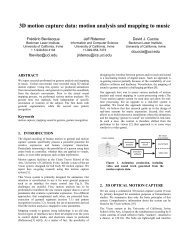
To Stereo InputPA MIXINGA. A Typical Live PerformanceIntroductionThere are so many different types of ‘live’ scenarios that itwould be almost impossible for us <strong>to</strong> describe each one in abook of these modest proportions. Instead, our ‘typical livegig’ is represented by a small band, whose set-up is shownin the “<strong>Mixing</strong> Live” diagram.MicrophonesMost of the microphones used in live applications aredynamic cardioids because they are <strong>to</strong>ugh, produce anintelligible sound and their directional response helpsprevent spill or feedback. Dynamic microphones canhandle anything from drums <strong>to</strong> vocals. However, condensertypes, with their greater sensitivity <strong>to</strong> high frequencies areinvariably used for jobs such as overhead pick-up on adrum kit or mic’ing acoustic instruments.Cables and ConnectionsInterference and hum can be avoided! A few minutes spentchecking cable runs and connec<strong>to</strong>rs pays dividends.• A balanced audio connection provides low noise operationby cancelling out any interference in a signal. It does thisby using a 2-conduc<strong>to</strong>r mic cable surrounded by a shield.Any interference picked up will be of the same polarity onthe two conduc<strong>to</strong>rs and is therefore rejected by the micinput’s Differential Amplifier.• Don’t skimp on interconnecting cables - always buy thebest that you can afford. Make sure that all connections aresound and keep cable runs as short as is practicable.• A multicore cable and stage box will keep trailing cables <strong>to</strong>a minimum and presents a tidy and practical approach.• If your mixer has a separate power supply unit, keep it wellaway from the console.• Where signal and mains cables must cross, make surethey’re at 90° <strong>to</strong> each other. This will help reduce the riskof hum and noise.• If the venue has a three-phase supply, don’t share the samephase as lighting controllers.SECTION 4: PA <strong>Mixing</strong>MIXING LIVEFIG. 4.1GUITAR VIADI BOXPA SPEAKERPA SPEAKERMICSONDRUMKITDI BOXKEYBOARD ORSYNTHESISERStereo Input RightStereo Input LeftPOWEREDMONITORPOWER AMPGRAPHIC EQMic 4MIC ONGUITAR AMPMic 1Mic 2Mic 3Mic 5Mix LAux PreMix RMixInsertsStereo Input• Basic moni<strong>to</strong>r mixing can be done fromFOH console as shown, using Aux Preoutput. For more detailed information onMoni<strong>to</strong>r <strong>Mixing</strong>, read Section 5.DIRECT OUTSMICLINEINSERTSAux PostEFFECTS UNIT17
SECTION 4: PA <strong>Mixing</strong>• It is dangerous <strong>to</strong> lift the mains earth when trying <strong>to</strong>eliminate hum. You can isolate hum by lifting theappropriate audio signal shield.• When using wireless mics, set the receiver on stage and runback <strong>to</strong> the console at balanced mic level. This will helpavoid interference from digital sources and lightingcontrollers.• Keep unbalanced ‘insert’ leads away from mains and keepthem short - no longer than about 2 metres.Connecting External Effects and ProcessorsWe talked about Effects and Processors in Sections 2 and 3,so you’re now aware of their functions and applications.Effects units are best connected via the console’s AuxiliarySend and Return Loop (sometimes known as the EffectsSend and Return Loop) or the Insert Point. When used inthe Aux Send system, the dry signal level should be turnedoff on the effects unit, but when used via Insert Points (forguidance on how <strong>to</strong> wire a jack for use with Insert Points,see Section 6), the dry/effects balance must be set on theeffects unit itself. Processors treat the whole of theincoming signal and therefore may only be used via consoleInsert Points or directly ‘in-line’ with a signal: they cannotbe used in the Aux Send/Return loop system.Setting Up• Position the mixing console so that you can hear the onstageperformance as the audience will hear it. Ensure thatyou have a clear view of the performers.• After setting up, switch the power amps on last <strong>to</strong> preventany thumps occurring when effects or instruments arepowered up. Ensure the console’s master gain is downbefore you switch on the amplifiers.• Don’t set up the vocal mic directly in front of the drum ki<strong>to</strong>r a guitar stack.• Make sure the speakers aren’t obstructed by the audienceand that the majority of the sound is being directed<strong>to</strong>wards the audience, not <strong>to</strong>wards the rear or side walls.• Set up the vocal levels first - it’s no use getting a great drumsound if the vocals feed back before they can even be heard.• Keep the vocals panned <strong>to</strong>wards the centre of the mix. No<strong>to</strong>nly will this sound more natural, but it will allow thegreatest vocal level before feedback or dis<strong>to</strong>rtion occurs.• Be sparing on the use of artificial reverb. Most venues are<strong>to</strong>o reverberant anyway, and excessive reverb will ruin theintelligibility of the vocal performance.• Do not use reverb on low frequency sound sources such asbass, kick drums and <strong>to</strong>m <strong>to</strong>ms.• Keep backline amp levels down: let the mic and mixer dothe work!• Always leave a little gain in hand so you can wind up thelevel slightly as the show progresses.• Putting high levels of bass guitar or kick drum through asmall PA can overload the system and dis<strong>to</strong>rt vocal quality.Try rolling off some of the low bass, you’ll get a highersubjective sound level without overload.Ringing Out: Nulling Room AcousticsCaution: Ringing out can cause howl around which candamage speakers, so use care when adjusting levels.As experienced engineers will tell you, there’s no such thingas a perfect venue. To help tailor the sound <strong>to</strong> the roomacoustics, insert a Graphic Equalizer in<strong>to</strong> the console’s mixinsert jacks which are effectively between the mixer and thepower amp.‘Ringing Out’ the system prior <strong>to</strong> the sound check will helpreduce troublesome feedback. To Ring Out, follow thisprocedure:1 Set all graphic EQ controls <strong>to</strong> centre (0).2 Turn up amp volume until feedback is just beginning <strong>to</strong>‘ring’.3 Turn back the amp volume slightly <strong>to</strong> prevent accidentalfeedback.4 Starting from the left, adjust the first graphic EQ frequencygain control <strong>to</strong> ‘max’: if the system doesn’t feedback, thenthis is not a problem frequency. Return this gain control <strong>to</strong>centre position.If the system feeds back, reduce the EQ gain by the sameamount you boosted <strong>to</strong> get feedback.5 Repeat this procedure for all graphic EQ frequencies.18
Setting the Mix• Turn down the amplifier gain before the system is firstswitched on. This will avoid unwelcome howls of feedbackand can prevent loudspeaker damage due <strong>to</strong> switch-ontransients.• Set all the channel EQs <strong>to</strong> their flat or neutral position andoptimize the input gain control setting for each channel inturn using PFLs.• If low frequency background noise is a problem, switch inthe High Pass Filter on each of the microphone channelsbeing used, except on low frequency sound sources such asbasses and kick drums.• Ring out the system as described above, with the vocal micsopen, and notch out any obvious trouble spots.• Establish the maximum working level for the lead vocal micso as not <strong>to</strong> incur feedback and then work a little belowthis level <strong>to</strong> allow a margin of safety. Again, see the noteson ringing out the system.• Set up the backing vocal mics and check that there is nofeedback problem when both the backing vocal and leadvocal mics are on. If there is, reduce the master gain settinguntil the feedback disappears.• Now the instrument and direct line inputs can be balancedrelative <strong>to</strong> the vocals. Start with drums and work through<strong>to</strong> the bass and rythm instruments.• Test out any effects units connected <strong>to</strong> the system andestablish the correct balance of dry and effected sound.Avoiding Feedback• Turn down or mute any mics not in use. This reduces therisk of feedback and avoids the back line being picked up.• If feedback is a real problem, consider moving the main PAspeakers away from the mics a little. Also check the back ofthe stage, because if the wall is acoustically reflective, somesound from the room will be reflected back in<strong>to</strong> the micsincreasing the risk of feedback.• Avoid excessive use of boosted EQ as this can encouragefeedback and may also spoil the basic character of thesound. Consider it an aid <strong>to</strong> fine tuning rather than as ameans of making radical changes.• The use of stage moni<strong>to</strong>rs will also worsen the feedbacksituation so run these at the lowest volume that theperformers can comfortably work with. Position thecabinets so as <strong>to</strong> allow as little direct sound as possible <strong>to</strong>enter the vocal microphones. If possible, use a graphic EQon each moni<strong>to</strong>r.NB: Remember, people soak up sound! The perfect mix achieved inan empty venue will have <strong>to</strong> be tweaked when the crowdsarrive. Sound waves are also affected by heat and humidity.SECTION 4: PA <strong>Mixing</strong>19
SECTION 4: PA <strong>Mixing</strong>B. Larger PerformancesAlthough the example shown in the ‘<strong>Mixing</strong> Live’ diagramshown at the beginning of this section is of a small band,the principles are the same no matter the size of the liveperformance or venue. However, for larger PAs additionalspeakers, moni<strong>to</strong>rs, effects and processors may be requiredas well as slightly different positioning for each of thesepieces of equipment. These additional requirements areoutlined below:Medium Sized VenuesThe console used will require more input channels. Forexample it is likely you will want <strong>to</strong> mic up all of thedrums, and there are also likely <strong>to</strong> be more instruments,backing singers and sound sources in general.More moni<strong>to</strong>r sends will also be required - a singlemoni<strong>to</strong>r will not be enough for larger bands. The bass anddrums will require a moni<strong>to</strong>r between them. The vocalistswill want a moni<strong>to</strong>r each so they can hear themselves abovethe band.More speaker outputs may be needed in larger venues sothat all the audience can be reached, without there being“holes” in the amplified audio signal. It may be necessary <strong>to</strong>record the event. This will require additional levelcontrolled stereo outputs or direct outs if a multitrack isbeing used.NB: For simplicity, these diagrams do NOT show any outboardequipment.Large Sized VenuesLarge venues will require a separate “Front of House”(FOH) console for the audience mix and a Moni<strong>to</strong>r consolefor the band, as with a larger stage area each band memberwill require at least one moni<strong>to</strong>r wedge. The auxiliary sendsystem of the FOH console will not be able <strong>to</strong> cope withthese demands alone as it will have <strong>to</strong> deal with severaleffects units.The FOH console will have a large number of mic/lineinputs, plus a large number of matrix outputs so that acomplex range of speaker clusters can be placed around theaudi<strong>to</strong>rium.SMALL VENUESFIG. 4.2LEFT SPEAKERRIGHT SPEAKERWEDGE MONITORSWEDGE MONITORSAMPAMPAUDIENCEAUX PREOUTPUTSMIXERMIXOUTAUDIENCE20
MEDIUM SIZED VENUESDRUMMER'SMONITORFIG. 4.3LEFT SPEAKERMID/HISPEAKERSUB SPEAKERWEDGE MONITORSACTIVECROSSOVERAUDIENCEMIXMID/HIAMPSUBAMPMIXERAMPSAUX PRE OUTSWEDGE MONITORSAUDIENCERIGHT SPEAKERMID/HISPEAKERSUB SPEAKERSECTION 4: PA <strong>Mixing</strong>LARGER VENUESDRUMMER'SMONITORLEFTSPEAKERSMID/HISUBAMPX-OVERRxWEDGE MONITORSIN-EARMONITORSTxAMPSMONITORDESKRIGHTSPEAKERSMID/HISUBCENTRE VOCALSPEAKER(suspended)INSTRUMENTS& MICSSPLITTERAUDIENCEFIG. 4.4MULTICOREOUTPUTSFOH CONSOLEMULTICOREINPUTS21
SECTION 4: PA <strong>Mixing</strong>C. Recording LiveIn some situations, you may want <strong>to</strong> record a performance.Depending on the situation, the feed for recording maycome from the FOH mixer, microphone splitter boxes, oryour own microphones which have been set up alongsidethose of the band.The diagram below shows a typical example of the soundsources being split between FOH and Recording. Therecording console operates independently from the FOHmixer.NB: When using Folio SX it will be necessary <strong>to</strong> re-patch formultitrack playback.NB: Subgroups can be used for submixing many inputs (e.g. drums)<strong>to</strong> a multitrack input. This is useful when tape trackavailability is limited.Hints & Tips• Try <strong>to</strong> locate the mixer in a different room <strong>to</strong> theperformance <strong>to</strong> avoid distraction from the live sound.If this is not possible, use a good pair of noise-excludingheadphones for moni<strong>to</strong>ring.• Wherever possible, take feeds from mic splitters - thiswill provide clean, low-noise signals suitable forrecording.• Often, Tape Sends are unbalanced, so keep signal paths asshort as possible between output and recorder <strong>to</strong> avoidinterference.• If there aren’t enough microphones, use a stereo pair <strong>to</strong>pick up the overall sound and the rest <strong>to</strong> emphasizeindividual performers.• Use a compressor/limiter <strong>to</strong> avoid overloading the digitalinput of the recorder.FIG. 4.5RECORDING LIVEFrom mics andinstrumentsTo Mic/Line inputsMULTITRACK TAPEMACHINESPLITTERPost-FadeDirect OutputsDirect OutMicLineFRONT-OF-HOUSECONSOLE(E.G. SPIRIT 8)RECORDINGENGINEER’SHEADPHONES
OTHER APPLICATIONSA. Moni<strong>to</strong>r <strong>Mixing</strong>Moni<strong>to</strong>rs are used <strong>to</strong> allow band members <strong>to</strong> hearthemselves.When dealing with the moni<strong>to</strong>ring requirements of, say,a large live band, it is common practice <strong>to</strong> keep themoni<strong>to</strong>r mix function <strong>to</strong>tally separate from the Front ofHouse console.Some form of graphic equaliser in line with each moni<strong>to</strong>rspeaker is desirable as it allows troublesome frequencies <strong>to</strong>be notched out. The moni<strong>to</strong>r system is rung out in exactlythe same way as the main PA (see Ringing Out Section 4),and the final ringing out must be done with both themoni<strong>to</strong>r and main PA systems set at their normal operatinglevel.The moni<strong>to</strong>ring console is situated off-stage andderives its feed direct from mic splitters. Note: the SpiritMoni<strong>to</strong>r 2 console has its own built-in mic splitters.• It is normal for a telecommunication link <strong>to</strong> be usedbetween the FOH and moni<strong>to</strong>r engineer so that they cantalk <strong>to</strong> each other during the performance.• Each stage moni<strong>to</strong>r needs its own power amp. Keepthings tidy by using rack-mounted stereo amps.• Graphic EQs are patched via the console, like the poweramps they should be rack-mounted for easy access.• If the lead vocalist uses in-ear moni<strong>to</strong>ring, he/she will beacoustically isolated, so it’s a good idea <strong>to</strong> feed audiencepick-up mics in<strong>to</strong> his/her mix <strong>to</strong> provide a sense ofinvolvement.• ‘Side fills’ are often used where moni<strong>to</strong>ring is requiredover a large stage area, floor space is at a premium, and<strong>to</strong>o many wedge moni<strong>to</strong>rs would simply clutter things upboth physically and acoustically. Don’t compromise onthese speakers - they’ll have <strong>to</strong> work hard <strong>to</strong> punch soundthrough <strong>to</strong> the performers.• The Moni<strong>to</strong>r Engineer’s wedge lets him hear the <strong>to</strong>talfoldback mix or selected parts thereof.• A good Moni<strong>to</strong>r Engineer, who is “invisible” <strong>to</strong> theaudience, will always position himself so as <strong>to</strong> see visualsignals from the performers.SECTION 5: Other ApplicationsMONITOR MIXFIG. 5.1SIDE FILL MONITORMULTICORE TOFRONT-OF-HOUSECONSOLEFROM MICS ANDINSTRUMENTSDRUMMER’SMONITOR* If the mixer has a builtinsplitter (e.g. SpiritMoni<strong>to</strong>r 2 console), anon-stage splitter is notrequired.SPLITTER*POWERAMPLIFIERSGRAPHICEQSSIDE FILLMONITORSTAGEMONITORSMoni<strong>to</strong>rOutputsEngineer’sWedge OutInsertsAMPMic InputsENGINEER’SMONITORHEADPHONES/TALKBACKTELECOM LINK23
B. SubmixingSECTION 5: Other ApplicationsThere are certain groups of instruments or performers(drums, backing vocals, multi-keyboards, etc) that canbe logically grouped <strong>to</strong>gether - <strong>to</strong> save on inputchannels - via a small mixer, the output of which canthen be controlled by just one pair of faders on themaster console.• If a mono output is available it can be used for a drumfill or for recording purposes.• Output from the submixer goes <strong>to</strong> the FOH consoleand/or may be used for a small recording set up.• Use the Aux Returns on the FOH console <strong>to</strong> return thesub-mix. This saves valuable input channels on the FOHconsole.• In the case of a drum kit where many mics are in closeproximity, the use of Noise Gates will prevent spill andclean-up the mix.• Use a Compressor/Limiter <strong>to</strong> maintain a consistent level.FIG. 5.2CONDENSER MICSOVERHEADSUBMIXINGDRUMMER’S MONITORAMPCOMPRESSOR/LIMITERMix L&RDRUMMACHINEMono OutputMic 5Mic 6Mic 8Mic 7Stereo InputMix L&RF1 OUTPUTTO MAINMIXERINPUTSMic 1Mic 3Mic 2Mic 4OPTIONAL NOISEGATES ON INPUTS 2-7(DYNAMIC MICS) TOCLEAN UP MIXMicChannelInsertsHEADPHONES24
IN THE STUDIOA. Essentials & ErgonomicsThink about room layout and equipment. No, we’re notgoing <strong>to</strong> plan your studio for you, but here are a fewpointers:• If you play keyboards, set them up so that you can reachthe mixer.• Position your effects and synth modules within armslength.• If you use a computer, position the screen so as <strong>to</strong> avoidreflections. Do not position speakers near the screenunless they are magnetically compensated or shielded.• If the room is <strong>to</strong>o ‘live’, deaden it with drapes or softfurnishings.• For best results, use dedicated nearfield moni<strong>to</strong>rs.• Don’t use large speakers in a small room - they’ll soundwrong at low frequencies.• Do use a well specified power amp (minimum 50 wattsper channel).• Don’t compromise on a weedy amp: it will dis<strong>to</strong>rt at highlevels and may damage the speakers.B. Tape Machines &Recording MediaBasically, you’ll need two types of tape machine: amultitrack recorder for recording the individual parts ofthe performance in readiness for mixdown on<strong>to</strong> a 2-trackrecorder for mastering. There are both analogue and digitalmodels available. The final choice must be based onindividual requirements.C. The ConsoleStudio work presents additional problems for a mixingconsole in that it has <strong>to</strong> deal with a two stage processrequiring very different skills.1 Recording - Sound sources have <strong>to</strong> be captured onmultitrack tape. This process will include ensuring that thecleanest strongest signal is being recorded <strong>to</strong> tape, withou<strong>to</strong>verload and dis<strong>to</strong>rtion, optimising the sound of therecorded signal with EQ, signal processing and effects,moni<strong>to</strong>ring the recorded sources, and creating a headphonemix for the musicians <strong>to</strong> ensure the best possibleperformance from them.2 Mixdown - All the recorded sound sources as well as any“live” media coming from sequencers, drum machines orsamplers must then be blended <strong>to</strong>gether using EQ, level,pan and effects and mastered down <strong>to</strong> a two-track device <strong>to</strong>create a “final mix”. This process bears some similarities <strong>to</strong>mixing a band - minus the audience, the live performanceand poor venue acoustics!If you have seen any T.V. shows including footage ofcommercial recording studios you may be forgiven forthinking that good multitrack recordings are only possibleusing a mammoth console. This does not have <strong>to</strong> be thecase! Professional sounding results can be achieved, albeitwith some repatching between recording and mixdownstages, using a relatively small multipurpose mixer.However, <strong>to</strong> achieve professional results the mixer must beequipped with either (and preferably both):• Direct outs• Groups/SubsWhen purchasing a console for both live and recordingwork, ensuring these facilities are available will save youhaving <strong>to</strong> buy a dedicated recording console until yourrequirements become more sophisticted.SECTION 6: In the Studio25
SECTION 6: In the StudioD. Simple Multitrack RecordingThe diagram below shows a simple recording set-up using amultipurpose console equipped with direct outs and a pairof subgroups. The sound from instruments or voices istaken straight out <strong>to</strong> be recorded by the multitrack, withrecorded signals being returned from the multitrack’schannels in<strong>to</strong> spare inputs of the mixer so they can bemoni<strong>to</strong>red. Alternatively, backing vocals or groupedinstruments such as drumkits may be recorded <strong>to</strong> single orpairs of tracks by subgrouping them and connecting themixer’s group outputs <strong>to</strong> the multitrack device.The engineer moni<strong>to</strong>rs both performances and previouslyrecorded material through a moni<strong>to</strong>r amp and speakers,with the performers getting their own separate foldbackmix through the auxiliary sends .Hints and Tips when Recording:• If you are recording as a solo performer on a budget, youcan avoid the expense of buying a separate amp <strong>to</strong> create aheadphone mix. Plug your headphones in<strong>to</strong> the console’sheadphone connec<strong>to</strong>r and use its moni<strong>to</strong>r mix for yourfoldback. Alter channel fader levels as you wish <strong>to</strong> achieveoptimum headphone levels for your performance.• If your console is not large enough <strong>to</strong> cope with everymultitrack send and return, connect only as many DirectOuts as you need per take. For example, if you arerecording solo you will only be recording one instrument ata time anyway, so a maximum of only two direct outs willbe required for stereo instruments, and one for mono ones.The same channel direct outs may then be repatched <strong>to</strong>adjacent multitrack tape ins <strong>to</strong> record new tracks. Thisshould leave enough channels free <strong>to</strong> moni<strong>to</strong>r all yourrecorded tracks.• If you run out of tape tracks, group instruments <strong>to</strong>gether.For example a fully mic’d up drumkit can be recorded instereo <strong>to</strong> two tape tracks via a pair of groups, or if you arereally stretched you could do this with the entire rhythmsection, including bass and rhythm guitar. However, it isthen essential <strong>to</strong> mix the balance between the instrumentsaccurately as, once recorded, they can never be individuallyaltered again.• If you have only one effects unit and you need it <strong>to</strong> create avariety of different sounds, it may be neccessary <strong>to</strong> recordthe instrument with effects included. Again, remember tha<strong>to</strong>nce you have done this there is no going back, so whereverpossible it is best <strong>to</strong> record “dry” and buy a second effectsunit if you can. If you must record “wet”, look at youFIG. 6.1MULTITRACK RECORDINGMultitrack recording is either via open-reel or stacked AdatsMUSICIANS’MONITORHEADPHONESDRUMSBASSLEADRHYTHMVOCALSKEYBOARDS ORSYNTHESISERSStereo InputStereo InputMULTITRACK RECORDERHEADPHONE AMPEFFECTSMic 2NEARFIELDMONITORMic 1Aux PostDI BOXMic 3NEARFIELDMONITORSub L&RStereo InputAux PreMoni<strong>to</strong>r L&RSTEREOPOWERAMPENGINEER’SHEADPHONESDirect OutMicLineSpirit SX, with its 12 mono and 8 stereoinputs is suitable for the smaller studio26
mixer’s block diagram and use outputs coming after theeffects return for this purpose.• Do not record in the same room in which you are playingunless your moni<strong>to</strong>r speakers are muted. At the very least,your recorded track will pick up the mix from the moni<strong>to</strong>rspeakers, but more likely howl-round and feedback willoccur which will damage your equipment. If you arecording a band, it is best <strong>to</strong> put them in an entirelydifferent room al<strong>to</strong>gether.• Setting recording levels - for the best results, as it isimportant <strong>to</strong> set the highest record levels you can on yourmultitrack without getting overload or dis<strong>to</strong>rtion. If you setlevels <strong>to</strong>o low, you will end up with a weak signal andbackground hiss. All multitrack recorders allow you <strong>to</strong> setrecord levels before a take. Consult the recorder’s manual as<strong>to</strong> how best <strong>to</strong> achieve this.E. Simple Multitrack MixdownThe diagram below shows how a simple set-up will look forthe mixdown process. Some repatching has occured <strong>to</strong> freeup the input channels which were used as mutitrack tapesends. Tape returns can then be plugged in<strong>to</strong> the mixer insequence from channel 1 upwards, leaving any spare inputsfor sequenced MIDI instruments. Effects, amps andspeakers may be left as before.NB: Mixdown hints and tips may be found in “Creating a Mix” atthe end of this section.SECTION 6: In the StudioFIG. 6.2SIMPLE MULTITRACK MIXDOWNKEYBOARDS ORSYNTHESISERSInOutDATEFFECTSPERSONAL COMPUTERInOutMIDIMULTITRACKRECORDER2 TrackAux PostNEARFIELDMONITOROutMIDILine InputsStereo InputSOUNDMODULEInMIDIOutMIDIInAux PreMix L&RMixL&RSTEREOPOWERAMPNEARFIELDMONITORLine InputsMoni<strong>to</strong>rStereo InputsLineENGINEER’SHEADPHONES27
SECTION 6: In the StudioF. Using a Dedicated“In-Line” <strong>Mixing</strong> ConsoleFor recording projects beyond 8 track, amultipurpose console is usually inadequate, beingunable <strong>to</strong> cope with the additional multitracksends and returns and with all the repatching thatis required between recording and mixdown. Insuch cases, a dedicated “in-line” recording consoleis necessary. An example of the input strip of sucha console is shown here.Virtually all of the features and facilities areidentical <strong>to</strong> a standard mixer - except one: As wellas including full channel input facilities and adirect out (here called a tape send), the strip alsoincludes an extra input for a multitrack tapereturn as well as some basic rotary level controland pan facilities for that input. This secondinput is known as the Moni<strong>to</strong>r Input or Moni<strong>to</strong>rReturn. Using this technique allows a signal <strong>to</strong>and from a multitrack <strong>to</strong> be handled by oneinput strip, saving space and avoiding theconfusion of having <strong>to</strong> find corresponding sendand return signals in different areas of theconsole.The major advantage of using an “in-line”recording console is that repatching isunnecessary. This is because both channel andtape return inputs can be swapped (using theswitch marked “Chan/Mntr Input Rev”), givingthe signal coming from multitrack all the EQ,Auxiliaries and the linear fader of the channelinput for the mixdown process. This also leavesthe moni<strong>to</strong>r input free for sequenced MIDI gearsuch as keyboards. If more facilities are requiredfor these sound sources, then EQ and auxiliariesmay be shared between the two inputs.With two inputs per channel, a 16 channel “inline”consoleactually has 32 inputs available. Thishigh input count and compactness has made “in -line” consoles extremely popular with projectstudios, programming and remixing suites andcommercially successful bands’ home studios.With prices tumbling all the time, “in-line”consoles are now barely more expensive thanstandard designs.23SENDTRACKRETURNINSERTLINEMIC+48vDIRECT– 0 +TAPETRIM10 20GAINHFLFLINE-20dB10CHAN/MNTRINPUT REVHMIDLMIDCHANFB1AUX1AUX2MNTRFB2AUX3AUX4MNTRPANMNTRFDRCHANPAN2015– 0 +3 36 69 912 1215 – 0 + 153 36 69 912 1215 15EQ TOMNTR1k2k8k500 16KHZ– 0 +3 36 69 912 1215 15200 30010040080050 1.6KHZ– 0 +3 36 69 912 1215 150 10– 0 +3 36 69 912 1215 15– 0 +3 36 69 912 1215 15– 0 +3 36 69 912 1215 1501 12 23 34 4L 5 5 R000CHANPFLON10101001 12 23 34 4L 5 5 RPFLON105051015203030PKPK4060dB3k4kMIX1-23-45-67-8Multitrack Recording and <strong>Mixing</strong> with an“In-Line” ConsoleA more complex recording set up with an “in-line” consoleis shown opposite in Fig 6.4. Both multitrack ins and outsare plugged in<strong>to</strong> the same channel strip, avoiding the needfor repatching, whilst for sound proofing purposes,musicians are recorded in a separate room. Effects andsignal processors are connected in an identical way <strong>to</strong> anyother console via auxiliary sends and returns and insertpoints.G. Recording Instrumentsand VoicesVOCALS• Use a cardioid condenser mic positioned 9 inches(225mm) from the singer.• A pop shield will reduce explosive ‘p’ and ‘t’ sounds.• If sibilance is a problem, change <strong>to</strong> a dynamic mic ormove the singer back from the mic.Recommended effects/processor settings:EQ: Not normally required. But, if necessary, use the HPF(High Pass Filter) <strong>to</strong> reduce rumble.Compressor: Attack as fast as possible;Release around 0.5S, ratio between 4:1 and 8:1.Reverb: Try a decay time of around 3 seconds and a predelayof 50mS.DRUMS• Place mics 2 inches (50mm) from the heads of snare andkick drum.• For the kick drum, place the mic inside - pointingdirectly at where the beater strikes the drumhead.• To fully mic a kit, use separate mics on all <strong>to</strong>ms and hats.• Use condenser mics 5ft (1.5m) overhead, spaced around5ft (1.5m) apart, <strong>to</strong> pick up the entire drum sound,cymbals and “ambience”.Recommended effects/processor settings:EQ: Boost at: 80Hz <strong>to</strong> add weight <strong>to</strong> kick drums, 6kHz <strong>to</strong>add sizzle <strong>to</strong> cymbals or edge <strong>to</strong> a snare. Cut at 250-300Hz<strong>to</strong> reduce boxiness on a kick drum or low <strong>to</strong>ms.Gate: Fast attack setting <strong>to</strong> allow percussive transients <strong>to</strong>pass through. Precise settings will depend on microphonetype and placement.Reverb: Keep kick drum ‘dry’. Try a percussion platesetting with a 2.5S decay time on other drums.40∞FIG. 6.32823
ELECTRIC GUITAR• Some players prefer the sound of a valve amplifier, so beprepared <strong>to</strong> mic up the speaker cabinet using a cardioiddynamic mic.• Experiment with mic positioning <strong>to</strong> achieve the desiredsound.• If preferred, the guitar can be DI’d via a recordingpreamp which incorporates an amp simula<strong>to</strong>r.Recommended effects/processor settings:EQ: Boost at: 120Hz <strong>to</strong> add ‘thump’ <strong>to</strong> rock guitars, 2-3kHz <strong>to</strong> add bite, 5-7 kHz <strong>to</strong> add zing <strong>to</strong> clean rhythmsound. Cut at: 200-300Hz <strong>to</strong> reduce boxiness, 4kHz andabove <strong>to</strong> reduce buzziness.Compressor: Attack between 10 and 50mS; Release,around 0.3S, Ratio, between 4:1 and 12:1. Because of thenoise generated by a typical electric guitar, use inconjunction with a gate or expander is advised.Reverb: Plate or room, 1.5 <strong>to</strong> 4S; 30 <strong>to</strong> 60mS pre-delay.ACOUSTIC GUITAR• Use the best mic that you can, preferably a condensertype.• For a natural <strong>to</strong>ne, position the mic between 12-18insfrom the guitar, aiming at where the neck joins the body.• If recording in stereo, point a second mic <strong>to</strong>wards thecentre of the neck, about 12-18ins from the instrument.• Acoustic guitars sound best in slightly live rooms, ifnecessary place a piece of acoustically reflective boardbeneath the player.Recommended effects/processor settings:EQ: Boost: between 5kHz and 10kHz <strong>to</strong> add sparkle. Cutbetween: 1kHz and 3kHz <strong>to</strong> reduce harshness, 100 and200Hz <strong>to</strong> reduce boom. In busy pop mixes you can cut thelow end <strong>to</strong> produce a more cutting rhythm sound.Compressor: Attack 20 mS; Release, around 0.5S, Ratio,between 4:1 and 12:1.Reverb: Bright setting such as Plate <strong>to</strong> add vitality. Decaytime of between 2 <strong>to</strong> 3S.BASS GUITAR• Most engineers DI the bass via an active DI box and acompressor. This provides a clearer sound.• Use the compressor <strong>to</strong> keep signal peaks under control.• Check the player’s technique; the harder the instrumentis played, the brighter the <strong>to</strong>ne.• Consider the use of a budget graphic EQ.Recommended effects/processor settings:EQ: Boost: at 80-100Hz <strong>to</strong> add more weight and punch,between 2 and 4kHz <strong>to</strong> add edge. Cut: below 50Hz <strong>to</strong>SECTION 6: In the StudioFIG. 6.4MULTITRACK RECORDING & MIXDOWNNEARFIELDMONITORNEARFIELDMONITORSTEREOPOWER AMPControlRoomL&RDATRECORDER2 TrackMULTITRACKRECORDERMix L&RINSTRUMENTSTo Line InputsMICROPHONESTo Mic InputsTape SendTape ReturnInsertLineMicInsertsPROCESSORS(NOISE GATES,COMPRESSOR/LIMITERS,AURAL EXCITERS)29
SECTION 6: In the Studioreduce unwanted rumble, between 180 and 250Hz <strong>to</strong>reduce boxiness.Compressor: Attack around 50mS; Release, around 0.4S,Ratio, between 4:1 and 12:1.KEYBOARDS• Most electronic keyboards can be plugged directly in<strong>to</strong>the line inputs of the mixing console.• Bear in mind that the majority of contemporarysynthesizers etc, have stereo outputs and will require twomixer channels.• Most synthesizer sounds can be used withoutcompression, though they do benefit from effects such asreverb or chorus.• Overdriven keyboard sound may be created by feedingthe signal via guitar recording preamp.H. Planning a Session• You have a lot <strong>to</strong> remember during a session, so create atrack sheet <strong>to</strong> keep a log of what instrument is recordedon<strong>to</strong> what tape track, plus other relevant information.• Record rhythm sections first; drums, bass, and rhythmguitar.• Add vocals, solos, and additional instrumentation asoverdubs.• Decide whether you want <strong>to</strong> add effects at the mixingstage or while recording. If you can, try <strong>to</strong> keep a copy ofthe original “dry signal” on tape. You may wish <strong>to</strong> remixat a later date!• When recording vocals, ask the singer what instrumentsthey most need <strong>to</strong> hear in the headphone mix.I. Creating a MixGo in<strong>to</strong> ‘neutral’ before you start off -• Set all the Aux Sends <strong>to</strong> zero.• Set all EQ controls <strong>to</strong> their central positions.• Pull all the faders down.• All routing but<strong>to</strong>ns ‘up’.Organize your Subgroups• Put logical groups of sounds <strong>to</strong>gether.• Route drums <strong>to</strong> a stereo sub-group.• Consider grouping backing vocals.• Group multiple keyboards.Metering• Use the PFL metering system for each channel in turn <strong>to</strong>optimize the gain setting.• The PFL should just go in<strong>to</strong> yellow band of the metersection, although peaking in<strong>to</strong> the red area is acceptable.• Check all the effects units for correct input levels.• If fitted, use the Solo In Place function <strong>to</strong> checkindividual channels in isolation while retaining theiroriginal pan and level settings.J. Balancing the MixIf you don’t have a lot of mixing experience, it can help <strong>to</strong>set up the drums and bass balance first, then move on<strong>to</strong> thevocals and the other instruments. Don’t worry about finetuning the EQ or effects until your dry mix is somewherenear right.• Satisfy yourself that the mix is working in mono. Checkfor Phase problems.• Pan bass drums, bass guitar and lead vocals <strong>to</strong> centre -this will stabilize the mix.• Spread other instruments across the stereo stage asrequired, including backing singers.• EQ the mix as required.• Now add stereo effects as necessary <strong>to</strong> add <strong>to</strong> the illusionof space and width.• Check the balance of your final mix by listening <strong>to</strong> itfrom the next room through the adjoining door: forsome reason, this often shows up whether the vocals are<strong>to</strong>o loud or quiet.Hints & Tips• Clean the heads of analogue tape machines before everysession. Use cot<strong>to</strong>n buds dipped in Isopropyl Alcohol.• Check all instrument tunings before each take, becausethey have a tendency <strong>to</strong> change as the room warms up.• Make a pop shield from s<strong>to</strong>cking material stretchedacross a wire frame. This will minimise vocal “popping”.• Don’t skimp on cables and connec<strong>to</strong>rs; these can be asource of noise.30
WIRING & CONNECTORSFaulty connec<strong>to</strong>rs and cabling are some of the mostfrequent sources of noise and poor sounding systems.The following section should help you connect your systemcorrectly. It’s also worth spending a little time referring <strong>to</strong>all of your user manuals, as wiring conventions can varybetween manufacturers - see diagrams.BALANCED AND UNBALANCED MIC INPUTSFIG. 7.1 FIG. 7.2<strong>Soundcraft</strong> uses XLR sockets for its balanced mic inputs.The wiring convention for XLRs is: Pin 1 - Shield, Pin 2 -Hot (+ve) and Pin 3 - Cold (–ve).Balancing is a method of audio connection which cancelsany interference in a signal, <strong>to</strong> give low noise operation.This is achieved by using a 2-conduc<strong>to</strong>r mic cable, usuallysurrounded by a shield, in which the ‘hot’ and ‘cold’ signalsare opposite polarity. Any interference picked up will be ofthe same polarity on both hot and cold wires and will berejected by the mic input’s Difference Amplifier. You mayuse unbalanced sources when wired as shown. However, donot use unbalanced sources with Phan<strong>to</strong>m Power switchedon. The voltage on Pins 2 & 3 of the XLR connec<strong>to</strong>r maycause serious damage.BALANCED AND UNBALANCED LINE INPUTSLine inputs accept ‘A’ Gauge, 3-pole (Tip, Ring, Sleeve) 1/4inch jack wired as shown in Fig. 7.3.FIG. 7.3BALANCEDUNBALANCED INPUTUNBALANCEDBALANCED INPUTFIG. 7.4Note that for unbalanced operation the screen of the cable is wired<strong>to</strong> both the Ring and the Sleeve of the jack.INSERTSA Mixer insert point is a single, ‘A’ Gauge, 3-pole (stereo),switched jack socket (not unlike the headphone socket on ahi-fi amplifier). When a 3-pole jack is inserted the signalpath is interrupted. The signal is taken out of the mixer viathe plug tip, through an external piece of equipment andthen back <strong>to</strong> the mixer on the ring of the plug. A special Y-cord is required which has the stereo jack at one end andtwo mono jacks, for the processor’s input and output, atthe other. See Fig. 7.4.GROUND COMPENSATED OUTPUTSGround compensated outputs may, <strong>to</strong> all intents andpurposes, be treated as balanced outputs. Groundcompensation helps avoid hum loops when the console isfeeding in<strong>to</strong> an unbalanced piece of equipment. Essentially,the Ground Compensated output has three connections,much like a conventional balanced output, except that thepin normally designated ‘cold’ acts as a ‘ground sense’ lineenabling it <strong>to</strong> sense and cancel any ground hum present atthe output.FIG. 7.5FIG. 7.6The convention for XLRs is: Pin 1 - Shield, Pin 2 - Hot,Pin 3 - Ground Sense. For jacks, the wiring convention is:Tip - Hot, Ring - Ground Sense, Sleeve - Shield.For use with balanced destinations, the Ground Senseoutput may be treated as ‘cold’ allowing the connection <strong>to</strong>be made normally. Where the destination has anunbalanced jack input, a two-core (balanced-type) leadshould be made up as shown. Unbalanced jacks may also beplugged directly in<strong>to</strong> Ground Compensated Output jacksockets, but the benefit of hum rejection will be lost.IMPEDANCE BALANCED OUTPUTSImpedance Balanced Outputs are configured as normalbalanced outputs: Pin 1 - Shield, Pin 2 - Hot (+ve) and Pin3 - Cold (–ve). See Fig. 7.2.Impedance Balanced Outputs work on the principle thathot and cold terminals have the same resistance. Whenimpedance balanced outputs are used with a balancedinput, good rejection is achieved for both common-modeground voltages and electrostatic interference.Note: The cold terminal can be either shorted <strong>to</strong> ground locally orleft open-circuit for balanced and unbalanced operation.SECTION 7: Wiring Up & Connec<strong>to</strong>rs31
SECTION 8: GlossaryGLOSSARYACOUSTIC FEEDBACK (HOWLROUND)A whistling or howling noise caused by an amplified signal ‘feedingback’ in<strong>to</strong> the amplification chain via a microphone or guitar pickup.ACTIVE DI BOXA device which permits Direct Injection of signals from guitars, etc,in<strong>to</strong> the console. Incorporates circuitry <strong>to</strong> adjust gain and provideimpedance matching. Requires power and may be battery driven orsometimes ‘phan<strong>to</strong>m powered’ from a console.AFL (AFTER FADE LISTEN)A function that allows the opera<strong>to</strong>r <strong>to</strong> moni<strong>to</strong>r a post-fade signal.Used with Aux Masters.AMPLIFIERDevice that increases the level of an electrical signal.AMPLITUDESignal level, usually in volts.ANALOGUEAnalogy (n.): correspondence or partial similarity, using physicalvariables. For example; an analogue tape recorder s<strong>to</strong>res sound ontape in the form of a magnetic pattern which is a replica of theoriginal musical waveform.ASSIGNOn a mixing console, <strong>to</strong> switch or route a signal <strong>to</strong> a particularsignal path or combination of signal paths.ATTENUATETo decrease the level of a signal.AUXILIARY SENDLevel control feeding a dedicated bus for driving external effects ora foldback moni<strong>to</strong>ring system. An output from the consolecomprising a mix of signals from channels derived independently ofthe main stereo/group mixes. Typically the feeds <strong>to</strong> the mix areimplemented on rotary level controls.BACK-LINEStage parlance for the row of instrument amplifiers and loudspeakercabinets behind the performers, e.g. guitar amps.BALANCERelative level of the left and right channels of a stereo signal.BALANCEDA method of audio connection which ‘balances’ the signal betweentwo wires and a screen which carries no signal. Any interference ispicked up equally by the two wires, through common moderejection at the destination differential balanced input resulting incancellation of the interference signal. For balancing <strong>to</strong> be effective,both the sending and receiving device must have balanced outputand input stages respectively.BANDWIDTHA means of specifying the range of frequencies passed by anelectronic device such as an amplifier, mixer or filter.BARGRAPHA row of LEDs calibrated <strong>to</strong> indicate signal level.BOOST/CUT CONTROLA single EQ control which allows the range of frequencies passingthrough its filter <strong>to</strong> be either amplified or attenuated. The centreposition is usually the ‘flat’ or ‘neutral’ position.BUS or BUSSA defined set of conduc<strong>to</strong>rs along which signals may travel. A mixerhas several busses carrying the stereo mix, the groups, the PFLsignal, the aux sends, etc.CAPACITORSee CondenserCARDIOID PATTERNThe ‘heart-shaped’ polar response of a microphone meaning thatmost of the sound is picked up from the front. Mainly used forstage vocals or in any situation were sound has <strong>to</strong> be picked upfrom a concentrated area, i.e. drums.CHANNELA strip of controls in a mixing console relating <strong>to</strong> a single monoinput or a stereo input.CHIPIntegrated circuit; a multi-pinned device consisting of many circuitsencapsulated in plastic.CHORUSEffect created by doubling a signal and adding delay and pitchmodulation.CLIPPINGSevere form of audio dis<strong>to</strong>rtion which is the result of signal peaksexceeding the amplifier capacity. Normally caused by a limitation ofthe unit’s power supply.CLONEExact duplicate. Often refers <strong>to</strong> digital copies of digital tapes.CONDENSERElectrical component exhibiting capacitance (the ability <strong>to</strong>temporarily s<strong>to</strong>re electric current) and block direct current.CONDENSER MICROPHONEA type of microphone which picks up sound via a thin, flexiblediaphragm placed in proximity <strong>to</strong> a metal plate - as opposed <strong>to</strong> therigid diaphragm-and-coil system used by dynamic microphones.Condenser mics are very sensitive, especially <strong>to</strong> distant sounds andhigh frequencies. They have <strong>to</strong> be powered, which can be achievedby batteries, but for professional use a 48v DC PHANTOMPOWER supply is provided from the console via the balanced miccable.CONDUCTORA thing that conducts or transmits heat or electricity.COMPRESSORA device designed <strong>to</strong> control or reduce the dynamic range of anaudio signal.32
CROSSOVERA passive circuit, normally built in<strong>to</strong> a speaker system whichdivides the full-range audio signal from an amplifier in order <strong>to</strong>feed the individual drive units, ie: bass, midrange and treble.CUEINGTo put a piece of equipment in readiness <strong>to</strong> play a particular part ofthe recording material. Assisted on a mixing console by use of thePFL (Pre-Fade LIsten) facility.CUT-OFF FREQUENCYThe frequency at which the gain of an amplifier or filter has fallenby 3dB.DAT (DIGITAL AUDIO TAPE)High quality cassette based recording format which s<strong>to</strong>res signalsdigitally and therefore provides very high quality sound. Originally<strong>to</strong>uted for consumer use, but now firmly ensconced as aprofessional <strong>to</strong>ol.dB (DECIBEL)A ratio of two signal levels. Can be in Voltage, Watts or Currentunits.dBmVariation on dB referenced <strong>to</strong> 0dB = 1mW in<strong>to</strong> 600 ohms.dBuVariation on dB referenced <strong>to</strong> 0dB = 0.775 volts.dBVVariation on dB referenced <strong>to</strong> 0dB = 1 Volt.DETENTIn audio terms a click-s<strong>to</strong>p in the travel of a rotary or slide control,normally used <strong>to</strong> indicate ‘centre stereo’ on pan-pots or ‘zeroboost/cut’ on EQ controls.DI BOXA device allowing connections as explained below.DI (DIRECT INJECTION)The practice of connecting an electric musical instrument directly<strong>to</strong> the input of the mixing console, rather than <strong>to</strong> an amplifier andloudspeaker which is covered by a microphone feeding the console.DIGITAL DELAYThe creation of delay and echo effects in the digital domain.Thepremise being that, as digital signals are resistant <strong>to</strong> corruption, theprocess will not introduce additional noise or dis<strong>to</strong>rtion.DIGITAL REVERBReverberation effects created as above.DIGITALThe processing and s<strong>to</strong>rage of signals with sound- informationrepresented in a series of ‘1s’ and ‘0s’, or binary digits.DIRECT OUTPUTA pre-/post-fade, post-EQ line level output from the input channel,bypassing the summing amplifiers, typically for sending <strong>to</strong>individual tape tracks during recording.DRYSlang term for an original audio signal that has had no addedeffects.DYNAMIC RANGEThe ratio in decibels between the quietest and loudest sounds inthe audible range that the audio equipment will reproduce.DYNAMIC MICROPHONEA type which uses a thin diaphragm attached <strong>to</strong> a coil of wirearranged about a permanent magnet. Any variation in air pressureon the diaphragm will cause the coil <strong>to</strong> generate a minute electriccurrent which then requires amplification.EARTHSee GROUND.EFFECTSThe use of devices <strong>to</strong> alter or process the sound <strong>to</strong> add specialeffects eg; reverb, normally as a mix of the original (‘dry’) soundand the treated (‘wet’) version.EFFECTS RETURNAdditional mixer input designed <strong>to</strong> accommodate the output froman effects unit.EFFECTS LOOPConnection system that allows an external signal processor <strong>to</strong> beconnected in<strong>to</strong> the audio chain.EFFECTS SENDA post-fade auxiliary output used <strong>to</strong> add effects <strong>to</strong> a mix.ELECTRET MICROPHONEType of condenser microphone using a permanently chargedcapsule.ELECTRONIC CROSSOVERAn active device which divides the full range audio signal in<strong>to</strong>several narrower frequency bands (eg:low, mid and high), which arethen amplified and fed <strong>to</strong> the appropriate speaker drive units.ENCLOSED HEADPHONESTypes that completely enclose the ears and therefore provide goodexclusion of outside noise. Of particular use when moni<strong>to</strong>r mixingor recording live on stage.EQAbbreviation for equaliser or equalisation.EQUALISERA device that allows the boosting or cutting of selected bands offrequencies in the signal path.EXPANDERThe opposite of a compressor, an expander increases the dynamicrange of signals falling below a pre-determined threshold.FADERA linear control providing level adjustment. Favoured byprofessionals due <strong>to</strong> smoothness of activation and the ability <strong>to</strong> givean instant visual indication of status.SECTION 8: Glossary33
SECTION 8: Glossary34FILTERA filter is a device or network for separating waves on the basis oftheir frequencies.FOHAn acronym for Front Of House. In the entertainment world"House" is a collective term for the audience at a theatre, cinema,etc. Hence an FOH console will be situated "audience-side" of thestage. A "house" PA system refers <strong>to</strong> the main audio systemresponsible for the principal sound in the venue.FOLDBACKA feed sent back <strong>to</strong> the artistes via loudspeakers or headphones <strong>to</strong>enable them <strong>to</strong> moni<strong>to</strong>r the sounds they are producing.FOLDBACK SENDA pre-fade auxiliary output used <strong>to</strong> set up an independent moni<strong>to</strong>rmix for the performers.FREQUENCY RESPONSEThe variation in gain of a device with frequency.FSK (Frequency Shift Keying)A method of synchronisation which generates a series of electronic<strong>to</strong>nes related <strong>to</strong> the tempo of the music. These <strong>to</strong>nes may then berecord on a spare track of the multitrack recorder.FX UNITSlang term for Effects Unit. Typical effects units are delays, reverbs,pitch shifters, and chorus units.GAINGain is the fac<strong>to</strong>r of how much the level of a signal is increased oramplified. Normally expressed in decibels.GATEA user-adjustable electronic device that switches off the signal pathwhen the signal falls below a certain predetermined level orthreshold.Typically used <strong>to</strong> ensure silence between pauses in the signal duringvocal passages or <strong>to</strong> prevent ‘spill’ between the close-proximity,multiple mics on a drum kit.GRAPHIC EQUALISERDevice incorporating multiple narrow-band circuits allowing boostand cut of predetermined frequencies. Vertical fader controls areused which provide a ‘graphic’ representation of the adjustmentsacross the frequency range.GROUND COMPENSATIONA technique used <strong>to</strong> cancel out the effect of ground loops caused byconnections <strong>to</strong> external equipment.GROUNDGround and Earth are often assumed <strong>to</strong> be the same thing, butthey are not. Earth is for electrical safety, while Ground is the poin<strong>to</strong>f zero voltage in a circuit or system.GROUND LOOPA ground loop occurs when there are <strong>to</strong>o many ground points,allowing small electrical currents <strong>to</strong> flow.GROUPAn output in<strong>to</strong> which a group of signals can be mixed.HEADROOMThe available signal range above the nominal level before clippingoccurs.HERTZ (Hz)Cycles (or vibrations) per second.HIGH PASS FILTERA filter that rejects low frequencies below a set frequency, typically100Hz.IMPEDANCEThe AC resistance of a circuit which has both resistive and reactivecomponents.IMPEDANCE BALANCINGA technique used <strong>to</strong> minimise the effect of hum and interferencewhen connecting <strong>to</strong> external balanced inputs.INDUCTORReactive component that presents an increasing impedance withfrequency. A coil in a loudspeaker crossover is an induc<strong>to</strong>r.INSERT POINTA break point in the signal path <strong>to</strong> allow the connection of externaldevices, for example signal processors or <strong>to</strong> another mixer.K OHM, K Ω or kHzx 1000 ohms, x 1000 ohms and x 1000Hz respectively.LINE LEVELSignals at a nominal level of -10dBV <strong>to</strong> +4dBu, usually comingfrom a low impedance source such as keyboards, drummachines,etc.mA (milliampere)One thousandth of an ampere, a measure for small electricalcurrents.MIC SPLITTERA device which divides the output from a microphone in order <strong>to</strong>supply two signals, for example; FOH console and recording mixeror moni<strong>to</strong>r console.MIDBANDThe range of frequencies <strong>to</strong> which the human ear is most sensitive.MIDI<strong>Music</strong>al Instrument Digital Interface.MIXDOWNThe process of taking the outputs from a multitrack recorder,processing as required and combining all elements <strong>to</strong> create a stereo‘master’.MONITOR LOUDSPEAKERAny high quality loudspeaker which is used <strong>to</strong> check the quality orstatus of the signal.MTC (MIDI Time Code)An interpretation of SMPTE allowing the time code <strong>to</strong> come in aspart of the MIDI data stream.MULTICOREA cable with multiple cores allowing signals <strong>to</strong> be carriedindependently but within the same physical outer casing.
MUTE GROUPSA method of combining the on/off status of a selection of channelsunder a single control but<strong>to</strong>n.NEARFIELD MONITORA high quality, compact loudspeaker designed for use at a distanceof three <strong>to</strong> four feet from the opera<strong>to</strong>r. Their use ensures thatdetrimental room effects are minimised.NORMALISEA socket is said <strong>to</strong> be normalised when it is wired in such a waythat the original signal path is maintained unless a plug is insertedin<strong>to</strong> the socket. The most common examples of normalisedconnec<strong>to</strong>rs are the INSERT POINTS found on mixing consoles.OSCILLATORA <strong>to</strong>ne genera<strong>to</strong>r for test and line-up purposes.OVERDUBTo add another part <strong>to</strong> a multitrack recording or replace one of theexisting parts.OVERLOADTo exceed the operating capacity of an electronic or electricalcircuit.PAN (POT)Abbreviation of ‘panorama’: controls levels sent <strong>to</strong> left and righ<strong>to</strong>utputs. Allows positioning of signals within the stereo sound stage.PARAMETRIC EQUALISERA graphic equaliser in which the cut/boost, frequency andbandwidth are all adjustable.PASSIVEA circuit or component which does not amplify the signal or is notpowered.PATCH BAYA system of panel mounted connec<strong>to</strong>rs used <strong>to</strong> bring inputs andoutputs <strong>to</strong> a central point from where they can be routed usingplug-in patch cords.PATCH CORDShort cable used with patch bays.PEAKINGA signal of the maximum displacement from its mean (average)position.PHANTOM POWERThe +48v DC voltage applied equally <strong>to</strong> the two signal pins of abalanced mic input <strong>to</strong> provide powering for condensermicrophones.PHASEPhase is the fraction of the whole period that has elapsed, measuredfrom a fixed datum. A term used <strong>to</strong> describe the relationship of twoaudio signals: in-phase signals reinforce each other, out-of-phasesignals result in cancellation.PHONO PLUGA hi-fi connec<strong>to</strong>r developed by RCA and used extensively on semiprorecording equipment.POLARITYThe orientation of the positive and negative poles of an audioconnection. Normally, connections are made positive <strong>to</strong> positive,negative <strong>to</strong> negative and this would ensure correct polarity. If this isreversed the result will be out-of-phase signals (see PHASE above).POP SHIELDA device used in the studio, consisting of a thin mesh placedbetween the microphone and vocalist in order <strong>to</strong> reduce the‘explosive’ effects of ‘P’ and ‘T’ soundPOST-FADEThe point in the signal path after the channel or master fader andtherefore affected by fader position.PRE-FADE LISTEN (PFL)A function that allows the opera<strong>to</strong>r <strong>to</strong> moni<strong>to</strong>r the pre-fade signalin a channel before it reaches the main mix.PRE-FADEThe point in the signal path before the moni<strong>to</strong>r or master positionand therefore unaffected by the fader setting.PROCESSORA device which affects the whole of the signal passing through it,e.g. gate, compressor or equaliser.Q (Bandwidth)A measure of the sharpness of a bandpass filter. The higher thevalue of Q, the narrower the band of frequencies that passesthrough the filter.RESISTANCEOpposition <strong>to</strong> the flow of electrical current.REVERBAcoustic ambience created by multiple reflections in a confinedspace. A diffuse, continuously smooth decay of sound.RINGING OUTThe process of finding the problem frequencies in a room bysteadily increasing the gain of the system until feedback occurs. AGRAPHIC EQUALISER is then used <strong>to</strong> reduce the offendingfrequencies.ROLL-OFFA fall in gain at the extremes of the frequency response. The rate atwhich a filter attenuates a signal once it has passed the filter cut-offpoint.SEQUENCERComputer-based system for the recording, editing and replay ofMIDI music compositions.SHELVINGAn equaliser response affecting all frequencies above or below thebreak frequency i.e. a high-pass or low-pass derived response.SHORT CIRCUITThe situation where two electrical conduc<strong>to</strong>rs <strong>to</strong>uch.SIBILANCEn. sounding with a hiss. When certain phonics are exaggerated, ie:s, sh.SECTION 8: Glossary35
SECTION 8: Glossary36SIGNALElectrical representation of input such as sound.SIGNAL CHAINThe route taken by a signal from the input <strong>to</strong> a system through <strong>to</strong>its output.SIGNAL-TO-NOISE RATIOAn expression of the difference in level between the audio signaland the background noise of the device or system. Normallyexpressed in decibels.SMPTE (Society of Motion Picture and TelevisionEngineers)Time code developed for the film industry but now extensivelyused in music and recording. SMPTE is a real-time code and isrelated <strong>to</strong> hours, minutes, seconds and film or video frames ratherthan <strong>to</strong> musical tempo.SOLO-IN-PLACEA function that allows the opera<strong>to</strong>r <strong>to</strong> listen <strong>to</strong> a selected channelon it's own but complete with all relevant effects, by au<strong>to</strong>maticallymuting all other inputs.SOUNDCRAFTThe name found on some of the best-value professional audioequipment around.SOUND REINFORCEMENTThe process of amplifying or reinforcing on-stage sound (whetherfrom already-amplified or acoustic instruments/voices) withou<strong>to</strong>verpowering the original sound. Suitable for smaller venues andoften used solely <strong>to</strong> raise the level of the vocals above the back lineand drums.SPL (Sound Pressure Level)Intensity of sound measured in decibels.STEREOTwo channel system feeding left and right speakers <strong>to</strong> create theillusion of a continuous sound field. Stereo: from the Greek wordfor ‘solid’.STEREO RETURNAn input designed <strong>to</strong> receive any stereo line level source such as theoutput of effects or other external processing devices.STRIPETo record time code on<strong>to</strong> one track of a multitrack tape machine.SWEEP EQAn equaliser section (e.g. Midband EQ) which boosts or cuts avariable rather than fixed frequency.TALKBACKA system allowing the opera<strong>to</strong>r <strong>to</strong> speak <strong>to</strong> the artistes or <strong>to</strong> tape viathe auxiliary or group outputs.TAPE RETURNA line level input provided specifically <strong>to</strong> receive the playbackoutput of a tape machine.TRANSIENTAn instantaneous rise in the signal level e.g. a cymbal crash orsimilar.TRIM CONTROLA variable control which gives adjustment of signal level over alimited and predetermined range usually for calibration purposes.TRS JACKSA 3-pole jack with Tip, Ring and Sleeve connection. Sometimesreferred <strong>to</strong> as a stereo or A-gauge jack plug.UNBALANCEDA method of audio connection which uses a single signal wire andthe cable screen as the signal return.This method does not providethe same degree of noise immunity as a BALANCED connection.WETSlang term for a signal with added effects such asREVERBERATION, ECHO, DELAY or CHORUS.Y-LEADA lead split so that one source can feed two destinations. Y-leadsmay also be used in console insert points in which case a stereo jackplug at one end of the lead is split in<strong>to</strong> two mono jacks at theother.2-TRACK RETURNA line level stereo input on a mixing console designed <strong>to</strong> accept theoutput from a 2-Track recording device. May also be used as anadditional effects return, depending on the internal routing of themixer.
+48VMIC/LINEGAINMICINPUT1 2LINEINPUTDIRECTPRE / POSTDIRECTPREOUTPUTCH. 1 - 8 ONLYPOSTONFADERPANEQMIX /SUBPFL / ENABLEMIX /SUBAUX1AUX2AUX3AUX1AUX2AUX3+48V2 TRK+48VMIX /SUBPOWER3▲▲PFL/AFL BUSSUB RIGHT BUSSUB LEFT BUSMIX RIGHT BUSMIX LEFT BUSAUX BUSSESMONO INPUTS 1 - 12HF & LFEQHF & LFEQSTEREO INPUTS 15/16(19/20 SIMILAR)STEREO INPUTS 13/14(17/18 SIMILAR)STEREO INPUTS 13 - 20100HzHIGH PASSFILTERPFL /ENABLEONINSERTFADERBALMIX /SUBMASTERMIX LEFTMIX RIGHT2 TRACKPFL/AFLPFLENABLESUB LEFTAUX1(AUX 3 SIMILAR)AUX2 POSTAUX2 PREAUX2POST /PREINSERTINSERTFADERFADERSUBTO MIXMIX LMIX RAFL AFLFADERMONOL METER/PFL/AFLPHONESR METER/PFL/AFLMIXLEFTMIXRIGHTMONOOUTPHONESC/RM LC/RM RSUB LEFTOUTSUB RIGHTOUTAUX1( 3 )AUX2LRLRLRA Typical Block Diagram (Spirit SX shown)SUB RIGHTFADER37
Notes38
NotesE&OE. All contents © 2001 <strong>Soundcraft</strong>. No part of this publication may be copied, transmitted or s<strong>to</strong>red electronically or otherwise for commercial gain, although thecopyright holder will allow copying and distribution for personal or non-profit use.39