(2006) A 1H/19F minicoil NMR probe for solid-state NMR
(2006) A 1H/19F minicoil NMR probe for solid-state NMR
(2006) A 1H/19F minicoil NMR probe for solid-state NMR
- No tags were found...

You also want an ePaper? Increase the reach of your titles
YUMPU automatically turns print PDFs into web optimized ePapers that Google loves.
Journal of Magnetic Resonance 178 (<strong>2006</strong>) 65–71www.elsevier.com/locate/jmrA 1 H/ 19 F <strong>minicoil</strong> <strong>NMR</strong> <strong>probe</strong> <strong>for</strong> <strong>solid</strong>-<strong>state</strong> <strong>NMR</strong>:Application to 5-fluoroindolesSteffen P. Graether a,1 , Jeffrey S. DeVries a,1 , Robert McDonald b ,Melissa L. Rakovszky a , Brian D. Sykes a, *a CIHR Group in Protein Structure and Function, Department of Biochemistry, University of Alberta, Edmonton, Alta., Canada T6G 2H7b X-ray Crystallography Laboratory, Department of Chemistry, University of Alberta, Edmonton, Alta., Canada T6G 2G2Received 22 June 2005; revised 22 August 2005Available online 27 September 2005AbstractWe show that it is feasible to use a <strong>minicoil</strong> <strong>for</strong> <strong>solid</strong>-<strong>state</strong> 19 F 1 H <strong>NMR</strong> experiments that has short pulse widths, good RF homogeneity,and excellent signal-to-noise <strong>for</strong> small samples while using low power amplifiers typical to liquid-<strong>state</strong> <strong>NMR</strong>. The closely spacedresonant frequencies of 1 H and 19 F and the ubiquitous use of fluorine in modern plastics and electronic components present two majorchallenges in the design of a high-sensitivity, high-field 1 H/ 19 F <strong>probe</strong>. Through the selection of specific components, circuit design, andpulse sequence, we were able to build a <strong>probe</strong> that has low 19 F background and excellent separation of 1 H and 19 F signals. We determinethe principle components of the chemical shift anisotropy tensor of 5-fluoroindole-3-acetic acid (5FIAA) and 5-fluorotryptophan. Wealso solve the crystal structure of 5FIAA, determine the orientation dependence of the chemical shift of a single crystal of 5FIAA,and predict the 19 F chemical shift based on the orientation of the fluorine in the crystal. The results show that this 1 H/ 19 F <strong>probe</strong> is suitable<strong>for</strong> <strong>solid</strong>-<strong>state</strong> <strong>NMR</strong> experiments with low amounts of biological molecules that have been labeled with 19 F.Ó 2005 Elsevier Inc. All rights reserved.Keywords: Fluorine; Crystal structure; Minicoil; Probe design; Solid-<strong>state</strong>1. IntroductionBiomolecular <strong>NMR</strong> has always evolved to tackle problemsthat had been considered ‘‘too difficult’’ by developingnew methodologies. Recent examples include TROSY <strong>for</strong>large proteins [1], cold <strong>probe</strong>s [2,3], and microcoils [4] <strong>for</strong>low concentration samples, and <strong>solid</strong>-<strong>state</strong> <strong>NMR</strong> <strong>for</strong> membraneproteins [5,6]. A promising application is the use of19 F as a reporter group in biological molecules. Fluorine<strong>NMR</strong> has a number of advantages, including a nuclearspin of 1/2, a chemical shift anisotropy (CSA) on the orderof at least 100 ppm and high sensitivity due to a high-magnetogyricratio [7]. 19 F is also 100% naturally abundant,and the biological background is minimal since only six* Corresponding author. Fax: +1 780 492 0886.E-mail address: brian.sykes@ualberta.ca (B.D. Sykes).1 These authors contributed equally to this work.distinct natural compounds containing fluorine have beendescribed [8]. The stereochemical similarity of 19 F to bothH and OH groups allows it to be readily incorporated intoamino acids, nucleic acids, and drugs, where fluorine can beused to study their binding properties, structure, and orientationin a magnetic field. For a recent review on the use offluorine in biomolecular <strong>NMR</strong>, see Ulrich [9].There are, however, a number of difficulties in the use of19 F <strong>NMR</strong>. The c F and c H differ by 6%, necessitating theuse of elaborate filters and circuit design to prevent radiofrequency (RF) resonant signals at one frequency interferingwith that at the other in multipulse and broadbanddecoupling experiments. In a typical 19 F <strong>NMR</strong> experiment,microwatt signals from 19 F need to be measured while 1 Hirradiation is occurring at hundreds of watts. Additionally,the >100 ppm CSA results in rapidly decaying fids andrequires the collection of large sweepwidths, which cantax high-field spectrometers. Strong 1 H/ 19 F and 19 F/ 19 F1090-7807/$ - see front matter Ó 2005 Elsevier Inc. All rights reserved.doi:10.1016/j.jmr.2005.08.010
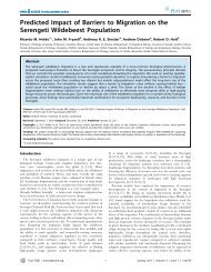
S.P. Graether et al. / Journal of Magnetic Resonance 178 (<strong>2006</strong>) 65–71 67diameter. The inside of the <strong>probe</strong> head consists of threesegments (Fig. 1B). The bottom segment was constructedfrom a grounded printed circuit board (PCB), on whichthe trimmer and chip capacitors and the coupling coil weresoldered. The middle segment consists of a 10-mm thickpiece of nylon to stabilize the sample coil from externalmechanical vibrations. The top segment contains the samplecoil. A 10-mm thick brass plate was inserted in the<strong>probe</strong> head cover, which provides a grounding shield fromexternal resonant frequencies above the sample coil. A 5-mm opening in the center of each segment allows <strong>for</strong> variabletemperature airflow. A semi-rigid, coax cable withPTFE dielectric was used <strong>for</strong> the transmit and receive pathsbetween the <strong>probe</strong> circuit and <strong>probe</strong> port because of itshigher power handling capabilities.In addition to low fluorine content, capacitors were chosenso as to be non-magnetic, small in size, capable of highworkingvoltages, and have low capacitance (picofaradrange). NMKT10HVE (1000 WVDC, Voltronics, Denville,NJ) trimmer capacitors were chosen <strong>for</strong> this application. Thechip capacitors chosen were 500 WVDC with a capacitanceof 7.5 pF (100B7R5CMS) and 36 pF (100B360GMS500)from American Technical Ceramic (Huntington Station,NY).5. Circuit designTo allow <strong>for</strong> separation of the closely spaced 1 H/ 19 F resonancesin high-power experiments, a series resonant,capacitor-coupled, band pass filter circuit was chosen(Fig. 2A). The basic circuit design consists of two resonantcircuits of L1 and C2, and C4, C5, and L2, where L1 designatesthe coupling coil, L2 designates the sample coil, andC designates the capacitors. The two circuits are coupledtogether via capacitors C3a and C3b. C3a is a trimmercapacitor that is adjusted so as to create an over-coupledcondition, resulting in a single port, double-tuned circuit[12]. A second set of capacitors (C1a and C1b) was placedat the beginning of the circuit in a parallel configuration toprovide proper impedence matching to a 50 X input. C1a isa trimmer capacitor that allows <strong>for</strong> fine tuning of thematching condition. The sample coil is balanced by placingtrimmer capacitors C4 and C5 on both ends in a series configuration(R. Chang and W. Brey, personal communication).These trimmer capacitors were adjusted until auni<strong>for</strong>m B 1 field was achieved (R. Chang and W. Brey, personalcommunication). The signal from the single port issplit into two channels using a directional coupler with1 H and 19 F bandpass filters (DP564-600-5BB, SpectrumFig. 2. (A) Circuit schematic. The physical series resonant, capacitor-coupled band pass filter used in the <strong>probe</strong>. The component labels are described in themain text. (B) Double-resonance tuning and matching at the 19 F resonant frequency.
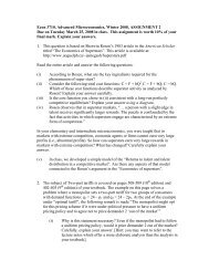
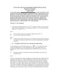
S.P. Graether et al. / Journal of Magnetic Resonance 178 (<strong>2006</strong>) 65–71 69AB20 0 -20 -40 -60 -80 -100 20 0 -20 -40 -60 -80 -10020 0 -20 -40 -60 -80 -100 20 0 -20 -40 -60 -80 -100<strong>19F</strong> (ppm)<strong>19F</strong> (ppm)Fig. 4. Powder pattern of two fluoroindoles. (A) Top, 5FIAA 19 F powder pattern, using a 90° pulsewidth of 2.0 ls, a recycle time of 200 s, and 352transients. Bottom, a simulation of the powder pattern using SIMPSON [14]. See the text <strong>for</strong> details. (B) Top, 5F-Trp 19 F powder pattern, using a 90°pulsewidth of 2.1 ls, a recycle time of 150 s, and 384 transients. Bottom, a SIMPSON simulation of the powder pattern. All experiments were collectedwith the DEPTH pulse sequence using a sweepwidth of 200,000 Hz and 1 H decoupling at cB 1 = 50 kHz. 1 H decoupling did not reduce S/N of the 19 Fsignal.after shifting d iso to 50.0 ppm, were d 11 = 4.0,d 22 = 65.5, and d 33 = 80.5 ppm. These differences mayreflect the fact that the 5F-Trp was in a lipid environmentor the mobility of the sidechains in the Grage et al.experiments.One use of fluorine labeled biological molecules in orientedsamples is to correlate the chemical shift of 19 Finthe molecule with the orientation of the fluorine atom relativeto the magnetic field [9]. To demonstrate the feasibilityof this approach, we produced a single crystal of5FIAA. Because the crystal was grown from a solvent mixturedifferent from that of the solved structure (3:2 methanol/watervs. 1:1:1 propan-2-ol/methanol/water [13]), wecollected several frames in order to index the unit cell.The result was different from the previous crystal structure,requiring the complete determination of the structure of5FIAA in our crystal (Fig. 5A). The molecules of thishydrogen-bonded dimer are crystallographically independent,i.e., they are not related by translational, rotational,or inversion symmetry, whereas in the previously reportedstructure, carboxylic acid dimers were <strong>for</strong>med by moleculesrelated by crystallographic inversion centers [13]. Thepacking of fluorine atoms in the crystal lattice is shownin Fig. 5B. The stacked rings result in the two crystallographicallyindependent molecules having two neighboringfluorines at 4.4 Å. The other neighboring fluorine atomsdiffer between the two molecules, in one case the neighboris 3.5 and 3.8 Å away, and in the other both fluorines are5.1 Å away.The faces of the pale yellow crystal (dimensions of0.9 · 0.3 · 0.3 mm 3 ) were indexed to provide an orientationof the unit cell in the laboratory frame (Fig. 6).The crystal was manually rotated in the <strong>minicoil</strong> from0° to 160° (Fig. 7A). The starting angle (0°) is definedas the 101 plane of the crystal being oriented perpendicularto B 0 , though subsequent data analysis found this tobe off by 20° due to imperfections on the 101 face andinaccuracies in the starting orientation in the capillary.Two sets of peaks are observed, one that may be an overlappeddoublet, the other which varies between a broaddoublet and a broad triplet. Lineshapes are Gaussian,which comes from the dipolar coupling between the multiplefluorine atoms in the crystal [16]. Simulations of thecrystal structure show that the difference in the splittingpatterns of the peaks can be explained by the 19 F/ 19 Fdipolar coupling interactions <strong>for</strong> the two crystallographicallyindependent molecules (Alexander Nevzorov, personalcommunication).Based on the determined crystal structure and therelationship:x CSA ¼ x 0 ðd 11 sin 2 hcos 2 / þ d 22 sin 2 hsin 2 / þ d 33 cos 2 hÞ; ð2Þwhere x 0 is the Larmor frequency, d aa is the relevant principalvalue of the CSA tensor, and h and / are the polarangles that describe the orientation of the CSA tensor relativeto B 0 , we can calculate the chemical shift at each orientationand compare them to the observed values. Theresults demonstrate that we are able to predict the chemical
70 S.P. Graether et al. / Journal of Magnetic Resonance 178 (<strong>2006</strong>) 65–71A101B4.45.14.490 o 0014.44.43.83.5Fig. 5. Crystal structure of 5FIAA. (A) Perspective view showing themode of crystallization of 5FIAA in this particular polymorph. Nonhydrogenatoms are represented by Gaussian ellipsoids at the 20%probability level. Hydrogen atoms are shown with arbitrarily smallthermal parameters. (B) Packing of fluorines in the unit cell. Distancesbetween fluorine atoms less than 6 Å are shown in the figure, with the twocrystallographically independent molecules shown separately.shift of the fluorine atom from its orientation in the laboratoryframe (Fig. 7B).7. ExperimentalThe Q value was measured by sweeping frequenciesfrom 550 to 610 MHz using an Agilent 83752A 0.01–20 GHz synthesized sweep generator while a Hewlett–Packard 87557 scalar network analyzer displayed thereflected power from a Mini Circuits ZF-DC-10-2 directionalcoupler connected to the <strong>probe</strong>.5-Fluoroindole-3-acetic acid (5FIAA, Product F4506,Molecular Formula C 10 H 8 FNO 2 , Formula Weight 193.17,CAS Number 443-73-2) and 5-fluorotryptophan (5F-Trp,Product F0896, Molecular Formula C 11 H 11 FN 2 O 2 , FormulaWeight 222.2, CAS Number 154-08-05) were purchasedfrom Sigma–Aldrich Canada (Oakville, ON). Samples weresealed in the capillary using the Triad gel (Dentsply Interna-Fig. 6. Crystal habit and faces. The crystal used in the <strong>NMR</strong> experimentswas first indexed by X-ray crystallography to determine the unit cellorientation in the laboratory frame.tional, York, PA), a non-fluorine liquid sealant that waspolymerized using UV light from an Optilux 501 UV source(Kerr Dentistry, Orange CA).Crystals of 5FIAA were grown after approximately 1month at room temperature by evaporation from a12.5 mg/mL solution of 3:2 methanol/water. Crystal data<strong>for</strong> 5FIAA: crystal system: monoclinic, space group: P2 1 /n(an alternate setting of P2 1 /c [No. 14]) with unit cell dimensionsa = 17.6080 (14) Å, b = 4.4529 (3) Å, c = 23.7724(18) Å, b = 110.8980 (11)°, V = 1741.3 (2) Å 3 , Z =8,q calcd = 1.474 g cm 3 , l = 0.118 mm 1 . A crystal fragmentof approximate dimensions of 0.50 · 0.32 · 0.26 mm 3 wasmounted in a non-specific orientation on a Bruker SMART1000 CCD PLATFORM diffractometer system. All intensitymeasurements were per<strong>for</strong>med using Mo Ka radiation(k = 0.71073 Å) with a graphite crystal incident beam monochromator.The intensity data were collected at 80° using xscans (0.3° scans, 15 s exposures). A total of 3587 independentreflections were collected to a maximum 2h limit at52.84°. The structure was solved by direct methods (SHEL-
S.P. Graether et al. / Journal of Magnetic Resonance 178 (<strong>2006</strong>) 65–71 71AB160 o140 o120 o100 o90 o80 o60 o40 o20 o200-20 -40 -60<strong>19F</strong> (ppm)-80-1000 o200-20 -40 -60<strong>19F</strong> (ppm)-80-100Fig. 7. Rotation of a single crystal in the <strong>minicoil</strong>. (A) The crystal was rotated by 10° or 20° increments after each DEPTH experiment (32 transients witha 2.1 ls90° pulse width and 500 s recycle delay). All experiments were collected with the DEPTH pulse sequence using a sweepwidth of 200,000 Hz and 1 Hdecoupling at cB 1 = 50 kHz. (B) Prediction of the chemical shift based on the orientation of the unit cell after each rotation.XS-86). Refinement of atomic parameters was carried out byusing full-matrix least-squares on F 2 (SHELXL-93), givingfinal agreement factors (R indices) of R 1 (F) = 0.0354 (<strong>for</strong>3008 data with I P 2 r(I)) and wR 2 (F 2 ) = 0.0997 (<strong>for</strong> all3587 unique data). Crystallographic data (excluding structurefactors) have been deposited at the Cambridge CrystallographicData Centre as supplementary publicationnumber CCDC 275074. Copies of the data can be obtainedfree of charge by application to CCDC, 12 Union Road,Cambridge CB2 1EZ, UK (Fax: +44 1223 336033 or, e-mail:deposit@ccdc.cam.ac.uk or, http://www.ccdc.cam.uk).AcknowledgmentsWe thank Drs. Christopher Grant and Chin (Albert)Wu at the University of Cali<strong>for</strong>nia (San Diego) <strong>for</strong> suggestionsregarding <strong>probe</strong> and experimental design; we alsothank Dr. Alexander Nevzorov at the University of Cali<strong>for</strong>nia(San Diego) <strong>for</strong> running simulations on the singlecrystaldata and Dr. Jan Rainey at the University of Alberta<strong>for</strong> help running the SIMPSON simulations on the powderdata. Dr. William Brey and Ran K. Chang at theNational High Magnetic Field Laboratory (Florida StateUniversity) are thanked <strong>for</strong> providing in<strong>for</strong>mation on thedesign and testing of an over-coupled circuit in an <strong>NMR</strong><strong>probe</strong>. We thank Dr. Paul Hazendonk at the Universityof Lethbridge <strong>for</strong> providing the principle components ofthe chemical shift tensor of 5F-Trp from 19 F MAS <strong>NMR</strong>experiments. Sam Graziano at the University of Albertais thanked <strong>for</strong> construction of <strong>probe</strong> body parts. Dr. BarryHoffman is thanked <strong>for</strong> providing Triad gel and an Optilux501 UV source.References[1] K. Pervushin, R. Riek, G. Wider, K. Wuthrich, Attenuated T-2relaxation by mutual cancellation of dipole–dipole coupling andchemical shift anisotropy indicates an avenue to <strong>NMR</strong> structures ofvery large biological macromolecules in solution, Proc. Natl. Acad.Sci. USA 94 (1997) 12366–12371.[2] P. Styles, N.F. Soffe, C.A. Scott, D.A. Cragg, F. Row, D.J. White,P.C.J. White, A high-resolution Nmr <strong>probe</strong> in which the coil andpreamplifier are cooled with liquid-helium, J. Magn. Reson. 60 (1984)397–404.[3] P. Styles, N.F. Soffe, C.A. Scott, An improved cryogenically cooled<strong>probe</strong> <strong>for</strong> high-resolution Nmr, J. Magn. Reson. 84 (1989) 376–378.[4] D.L. Olson, T.L. Peck, A.G. Webb, R.L. Magin, J.V. Sweedler, Highresolutionmicrocoil H-1-Nmr <strong>for</strong> mass-limited, nanoliter-volumesamples, Science 270 (1995) 1967–1970.[5] S.J. Opella, F.M. Marassi, Structure determination of membraneproteins by <strong>NMR</strong> spectroscopy, Chem. Rev. 104 (2004) 3587–3606.[6] A. Watts, S.K. Straus, S.L. Grage, M. Kamihira, Y.H. Lam, X. Zhao,Membrane protein structure determination using <strong>solid</strong>-<strong>state</strong> <strong>NMR</strong>,Methods Mol. Biol. 278 (2004) 403–473.[7] W.E. Hull, B.D. Sykes, Fluorotyrosine alkaline-phosphatase—internalmobility of individual tyrosines and role of chemical-shiftanisotropy As A F-19 nuclear spin relaxation mechanism in proteins,J. Mol. Biol. 98 (1975) 121–153.[8] D. OÕHagan, D.B. Harper, Fluorine-containing natural products, J.Fluor. Chem. 100 (1999) 127–133.[9] A.S. Ulrich, Solid <strong>state</strong> <strong>19F</strong> <strong>NMR</strong> methods <strong>for</strong> studying biomembranes,Prog. Nucl. Magn. Reson. Spectrosc. 46 (2005) 1–21.[10] T.L Peck, R.L. Magin, P.C. Lauterbur, Design and analysis ofmicrocoils <strong>for</strong> Nmr microscopy, J. Magn. Reson. B 108 (1995) 114–124.[11] D.G. Cory, W.M. Ritchey, Suppression of signals from the <strong>probe</strong> inbloch decay spectra, J. Magn. Reson. 80 (1988) 128–132.[12] S.L. Hu, J.A. Reimer, A.T. Bell, Single-input double-tuned circuit <strong>for</strong>double resonance nuclear magnetic resonance experiments, Rev. Sci.Instrum. 69 (1998) 477–478.[13] S. Antolic, B. KojicProdic, S. Tomic, B. Nigovic, V. Magnus, J.D.Cohen, Structural studies on monofluorinated derivatives of thephytohormone indole-3-acetic acid (auxin), Acta Crystallogr. B 52(1996) 651–661.[14] T. Vosegaard, A. Malmendal, N.C. Nielsen, The flexibility of SIMP-SON and SIMMOL <strong>for</strong> numerical simulations in <strong>solid</strong>- and liquid-<strong>state</strong><strong>NMR</strong> spectroscopy, Monatshefte Chem. 133 (2002) 1555–1574.[15] S.L. Grage, J.F. Wang, T.A. Cross, A.S. Ulrich, Solid-<strong>state</strong> F-19-<strong>NMR</strong> analysis of F-19-labeled tryptophan in gramicidin A in orientedmembranes, Biophys. J. 83 (2002) 3336–3350.[16] A. Abragam, Principles of Nuclear Magnetism, Clarendon Press,Ox<strong>for</strong>d, UK, 1961.