


Create successful ePaper yourself
Turn your PDF publications into a flip-book with our unique Google optimized e-Paper software.
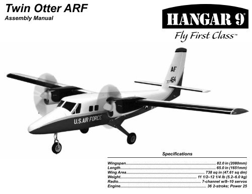
<strong>Twin</strong> <strong>Otter</strong> ARFAssembly <strong>Manual</strong>SpecificationsWingspan..................................................................................... 82.0 in (2080mm)Length.......................................................................................... 65.0 in (1651mm)Wing Area.......................................................................... 738 sq in (47.61 sq dm)Weight........................................................................ 11 1/2–12 1/4 lb (5.2–6.0 kg)Radio.............................................................................. 7-channel w/8–10 servosEngine................................................................................. 36 2-stroke; Power 25
2Table of ContentsContents of Kit and Parts Layout.................................2Included Hardware.......................................................3Introduction..................................................................4Important Warranty Information...................................4Recommended Setup–2-stroke Glow..........................4Recommended Setup–Electric Power (EP)................4Radio Equipment Requirements..................................4Transmitter Requirements...........................................4Required Tools and Equipment....................................4Required Adhesives.....................................................4UltraCote Covering Colors...........................................4Field Equipment Required...........................................4Other Required Items..................................................4Using the <strong>Manual</strong>.........................................................5Before Starting Assembly.............................................5Product Registration....................................................5Work Area Cleanliness.................................................5Optional Accessory......................................................5Workspace Preparation...............................................5Elevator Servo Installation...........................................6Aileron Servo Installation.............................................9Flap Servo Installation...............................................12Nacelle Installation.....................................................16Motor, ESC and Battery Installation............................17Cowling, Propeller and Spinner Installation–EP........202-Stroke Installation...................................................21Cowling, Propeller and Spinner Installation................27Rudder Hinging.........................................................28Rudder Servo and Linkage Installation.......................29Nose Gear and Steering Servo Installation..................32Main Landing Gear Installation..................................35Nose Cone Installation..............................................37Receiver, Battery and Switch Installation..................37Final Assembly...........................................................38Center of Gravity........................................................41Control Throws..........................................................41Flight Preparations.....................................................42Maintaining Your Model..............................................42Safety Do’s and Don’ts for Pilots................................43Dual Rates.................................................................43Age Requirements.....................................................43Daily Flight Checks....................................................43Flying Tips.................................................................44Build and Flying Notes...............................................44Warranty Information.................................................45Compliance Information for the European Union......462010 AMA Safety Code.............................................47Contents of Kit and Parts Layout1 HAN461001 Fuselage Assembly with Hatch 12 HAN461012 Left Main Gear2 HAN461002 Cowling 13 HAN461013 Right Main Gear3 HAN461003 Left Nacelle 14 HAN461014 Wing and Tail Tubes4 HAN461004 Right Nacelle 15 HAN461015 Landing Gear Fairings5 HAN461006 Left Stabilizer 16 HAN461020 2 1/4-inch Black Spinners6 HAN461005 Right Stabilizer 17 HAN461021 Fiberglass Nose Cone7 HAN461007 Rudder Not Illustrated8 HAN461008 Left Wing 1 HAN461016 Electric Mounting Pack9 HAN461009 Right Wing 2 HAN461017 Glow Mounting Pack10 HAN461010 Struts 3 HAN461018 Main Hardware Pack11 HAN461011 Nose Gear Assembly 4 HAN461019 Fuel Tanks<strong>Twin</strong> <strong>Otter</strong> ARF Assembly <strong>Manual</strong>
Included HardwarePackaged in KitFuselage assembly with hatch 1Fiberglass nose cone 1Right wing 1Left wing 1Right stabilizer with elevator 1Left stabilizer with elevator 1Right nacelle 1Left nacelle 1Rudder 1Cowling 2Right main landing gear with screws 1Left main landing gear with screws 1Nose leg assembly with screws 1Landing gear fairings (left and right) 2Wing struts (left and right) 23/4 x 19 1/2 inch aluminum wing tube 13/8 x 11 inch aluminum stabilizer tube 1Fuel tanks 200cc 22 1/4-inch white nylon spinners 2Main Hardware Bag8-32 x 1-inch Allen head machine screws 6 main landing gear#4 x 7/16-inch wood screws 3 nose cone4-40 x 1-inch Allen head machine screws 2 strut to wing attach8-32 x 1-inch Allen head machine screws 4 nose gear attachGlow Engine Mount BagSmall nylon engine mount 4 engine6-32 x 1-inch Allen head machine screws 8 engine mount6-32 blind nuts 8 engine mount#6 steel washers 4 engine mount4-40 x 1-inch Allen head machine screws 8 engine4-40 nylon lock nuts 8 engine#4 steel washers 16 engineElectric Power Mount Bag4-40 1 1/4-inch Allen head machine screws 8 motor3/8-inch diameter x 3/4-inch nylon standoffs 8 motorControl Horn BagSmall control horns 2 rudder#4 x 1/2 in Phillips head screws 4 rudder control hornsNylon clevises 9 steel pushrodsSnap keepers 9 steel pushrodsSilicone keepers 18 clevises1/4-20 x 2 in nylon screws 2 wing retentionPushrod Bag2-56 x 4-in steel pushrod 7 ailerons and flaps2-56 x 10-in steel pushrods 2 throttles2-56 x 7-in steel pushrod 1 nose gear steeringServo Mounting Bag10 x 11 x 20mm hardwood blocks 10 aileron and flap servos8 x 8 x 14mm hardwood blocks 4 elevator servos12-inch hook and loop straps 2 battery/fuel tank4-inch adhesive-backed hook and loop tape 3Hatch Screw Pack#2 x 3/8-inch woodscrews (silver) 12 servo hatches#2 x 1/4-inch woodscrews (black) 46 hatches and cowlsRudder Cable BagRudder cable 82 inch 1 rudder cablesCopper crimps 4Wire cable ends 2EZ links 2 rudder servo<strong>Twin</strong> <strong>Otter</strong> ARF Assembly <strong>Manual</strong>3
IntroductionHangar 9’s latest introduction, the <strong>Twin</strong> <strong>Otter</strong> is ascale model of the UV-18 ‘<strong>Twin</strong> <strong>Otter</strong>’, the militaryversion of the DeHavilland DHC-6. The trim schemeis based on the three UV-18B planes used by the USAir Force Academy cadet parachuting program whichcarry a pilot, copilot and up to 17 jumpers. There areonly three owned by the Air Force. Although this is amulti-engine model, the high-wing design and Clark Yairfoil improve low-speed handling and provide stableflight characteristics making this a great first-time twinfor intermediate to advanced pilots. The <strong>Twin</strong> <strong>Otter</strong>ARF also features an electric power option which addsto the reliability. It also features fiberglass cowlingsand fairings which make it very durable and easy torepair. The aircraft also includes fixed gear and largelanding flaps to provide easy and fun landings withoutthe addition of complicated landing gear necessary.Important Warranty InformationPlease read our Warranty and Liability Limitationssection on page 45 before assembling this product. Ifyou as the purchaser are not prepared to accept theliability associated with the use of this Product, you areadvised to return this Product immediately in new andunused condition to the place of purchase.Recommended Setup–2-Stroke Glow● Evolution® .36NT with muffler (EVOE0520) (2)● Evolution propeller 11x6 (EVO11060) (2)● Fuel dot filler (HAN115) (2)Recommended Setup–Electric Power● E-flite® Power 25 (EFLM4025A) (2)● E-flite 40-Amp Pro Switch-Mode BEC BrushlessESC (EFLA1040) (2)● E-flite 3200mAh 3S 11.1V 30 Li-Po(EFLB32003S30) (2)● APC Propeller 12x8E (APC12080E)Radio Equipment Requirements -7-Channel ReceiverThe following items are required when installing the7-Channel AR7000 receiver (SPM6070) in your aircraft:Spektrum A6000 Digital Servo (6) SPMSA6000JR SPORT MC35 Micro Servo (4) JSP20030(Note: Two less micro servos required for EP version)9-inch Servo Extension (7) JRPA09736-inch Servo Extension (2) JRPA103Y-Harness (3) JRPA135Receiver Battery, 6-volt, 2300mAh JRPB5006JR Chargeswitch JRPA004Ailerons: A6000 Servo (2)● 9-inch Extension (connected to servos) (2)● Y-harness (connected to receiver)Flaps: A6000 Servo (2)● 9-inch Extension (connected to receiver) (2)Elevator: MC35 Micro Servo (2)● 36-inch Extension (plugged into receiver) (2)Rudder: A6000 Servo● Y-harness (connected to receiver andnosewheel steering servo)Nosewheel Steering: A6000 Servo● 9-inch Extension (connected to servo)Throttles: MC35 Micro Servo (2)● Y-harness (connected to receiver)● 9-inch extension (connected to servo)(Also required for ESC connection)Transmitter RequirementsThe <strong>Twin</strong> <strong>Otter</strong> requires a minimum of a 5-channel radioto operate all the functions of your aircraft. We suggestthe following radio systems available through <strong>Horizon</strong><strong>Hobby</strong> or your local hobby distributor.Spektrum DX7JR X9303 2.4GHzSPM2710JRP2915Required Tools and EquipmentDrill motorPin viseLow-tack tape Needle-nose pliersRulerSidecuttersFileFelt-tipped penPencilCoarse grit sandpaperTapered reamer <strong>Hobby</strong> knife w/ #11 bladeDental floss Manila card stockAlcoholPaper towelsScissorsDouble-sided adhesive tapeMixing sticks Mixing cupsSmall cable ties T-pinsToothpicks StringPliersPencilRound fileZ-bend pliersPhillips screwdriver: #1, #2Rotary tool with cutoff wheel and sanding drumHex wrench: 3/32, 1/8, 7/64-inch, 1.5mm, 2.5mmOpen-end wrench: 5/16-inch, 10, 12, 13mmDrill bit: 3/64, 5/64, 3/32, 5/32, 9/64,11/64, 13/64-inchThin CAMedium CA30-minute epoxyThreadlockCanopy glueRequired Adhesives(PAAPT08)(PAAPT02)(PAAPT39)(PAAPT42)(PAAPT56)UltraCote Covering ColorsGolden YellowWhiteDeep Blue(HANU889)(HANU870)(HANU873)Field Equipment Required● Fuel (15% recommended)● Long Reach Glow Plug Wrench (HAN2510)● Metered Glow Driver with Ni-Cd & Charger (HAN7101)● 2-Cycle Sport Plug (EVOGP1)● <strong>Manual</strong> Fuel Pump (HAN118)4 <strong>Twin</strong> <strong>Otter</strong> ARF Assembly <strong>Manual</strong>
Using the <strong>Manual</strong>This manual is divided into sections to help makeassembly easier to understand, and to provide breaksbetween each major section. In addition, check boxeshave been placed next to each step to keep track ofcompleted sections. Steps with a single box () areperformed once, steps with two boxes () indicatethe step needs to be repeated, such as for left andright wing panel, or two servos etc. Note thatreferences to direction such as left and right-hand areas viewed in the direction of flight.Before beginning it is a good idea to read through themanual completely to familiarize yourself with theassembly process. Remember to take your time andfollow the directions.Before Starting AssemblyBefore beginning the assembly of your model, removeeach part from its bag for inspection. Closely inspectthe fuselage, wing panels, rudder and stabilizer fordamage. If you find any damaged or missing parts,contact the place of purchase.If you find any wrinkles in the covering, use a heat gunor covering iron to remove them. Use caution whileworking around areas where the colors overlap toprevent separating the colors.HAN100 – Heat GunHAN150 – Covering GloveProduct Registration<strong>Horizon</strong> <strong>Hobby</strong> wants to ensure that you get maximumenjoyment from your Hangar 9 products. We stronglyencourage you to register your product using theonline Product Registration tool so we can notify youwhen there are service bulletins, new option parts oraccessories, or updates available for your product.Please register your product today at:http://www.hangar-9.com/Register/Work Area CleanlinessIt is a good practice to maintain a clean work area,both to prevent damage to your model and to keeptrack of parts and hardware. Put away any tools notbeing used, and set aside parts of the model that arenot being worked on.Of special importance is keeping debris out ofsensitive components such as the radio and engine ormotor. Tape over engine intake and exhaust portswhen drilling or cutting the firewall and cowling toprevent causing damage to the internal components.Optional AccessorySetting up servos is a whole lot easier with a JR®MatchMaker. It lets you accurately center servos,evaluate endpoints, and cycle servos at varyingspeeds, without ever having to switch on a transmitter.It allows the precise digital centering of up to 2 servosat a time to help with setup on the building bench.Workspace PreparationDuring the course of building your <strong>Twin</strong> <strong>Otter</strong> wesuggest you use a soft base on the buildingsurface. Such things as a large piece of bedding foamor a thick bath towel work well to protect the modelfrom damage during assembly. A flat area measuringat least 28 x 60 inches is required to work on themodel sub-assemblies comfortably. The completedand assembled model requires a space of 48 x 96inches. Ensure you have adequate lighting, and aplace to set aside completed parts.The use of a stand to support the fuselage on theworkbench is highly recommended. This will hold itsecure while in different positions during assembly andprevent damage to items such as the tail that are notdesigned to support the weight of the model.Midwest Stand-In (MID813)HAN101 – Sealing IronHAN141 – Sealing Iron Sock<strong>Twin</strong> <strong>Otter</strong> ARF Assembly <strong>Manual</strong>5
Elevator Servo InstallationParts RequiredStabilizer halves (left and right)Micro servos with hardware (2)Snap keepers (2) Clevises (2)Silicone keepers (2) 4-inch steel pushrods (2)8 x 8 x 14mm servo mounting blocks (4)#2 x 3/8-inch woodscrews (8)Radio Step 2Use a #1 Phillips screwdriver to remove the small armfrom the servo. Use sidecutters to remove three armsfrom a standard 4-way servo arm, leaving one longarm. Center the servo using your radio and install thearm as shown. Step 4Enlarge the outer hole in the servo arm using a 5/64-inch drill bit in a pin vise, providing a servo arm lengthof 1/2 inch (13mm).Tools RequiredRulerSidecutters1/16-inch drill bitPliersFelt-tipped penThin CAMixing sticksZ-bend pliers#1 Phillips screwdriverPin vise5/64-inch drill bitPencilLow-tack tape30-minute epoxyMixing cups<strong>Hobby</strong> knife with #11 bladeNote: The left-hand elevator servo installation isshown here. Step 1Prepare two servos by installing rubber mountinggrommets and brass bushings. Note that the bushingsare installed from the bottom of the servo. Step 3Repeat step 2 to install the arm on the second servo,but install the arm in the opposite direction. Step 5Remove the elevator servo hatch from the lowersurface of the stabilizer. Place the servo against theinside surface of the hatch and use a ruler to positionit 1/4 inch from the aft end of the hatch.6 <strong>Twin</strong> <strong>Otter</strong> ARF Assembly <strong>Manual</strong>
Step 6Use a pencil to mark the servo location on the insideof the hatch. Step 8Set the servo in place on the mounting block witha 1/32-inch gap between the servo and the hatchsurface. Mark the servo mounting hole locations onthe blocks with a pencil. Step 10Use a #1 Phillips screwdriver and the hardwareprovided with the servo to install it on the hatch. Besure to maintain a 1/32-inch gap between the servoand the hatch surface. Step 7Mix a small amount of 30-minute epoxy and glue the8 x 8 x 14mm servo mounting blocks to the hatch. Step 9Remove the servo and use a 1/16-inch drill bit in a pinvise to drill the mounting holes. Apply a small drop ofthin CA to each of the holes to strengthen the wood.Allow the CA to cure without using accelerator. Step 11Use a hobby knife to trim the CA hinge where itprotrudes into the servo bay in the stabilizer. Becareful not to puncture the upper skin.<strong>Twin</strong> <strong>Otter</strong> ARF Assembly <strong>Manual</strong>7
Step 12Use a #1 Phillips screwdriver to thread a #2 x 3/8-inchwoodscrew into each of the mounting holes in thestabilizer. Remove the screw and apply a small dropof thin CA to each hole to harden the wood and helpretain the screw. Allow the CA to cure without usingaccelerator. Step 14Use a #1 Phillips screwdriver to secure the hatch tothe stabilizer with four #2 x 3/8-inch woodscrews. Step 16Center the elevator by aligning the balance tab to thestabilizer. Secure it in place with low-tack tape on boththe top and bottom sides. Step 13Feed the elevator servo lead through the forwardholes in the ribs to the stabilizer root and set the hatchin place. Step 15Slide a silicone keeper onto a 4-inch steel elevatorpushrod then thread on a clevis so it is centered onthe threads. Step 17Attach the clevis to the outer hole of the elevator horn.Use your radio to center the elevator servo then use afelt-tipped pen to mark the pushrod at the servo arm.8 <strong>Twin</strong> <strong>Otter</strong> ARF Assembly <strong>Manual</strong>
Step 18Remove the pushrod from the elevator horn and usepliers to make a 90-degree bend in the pushrod at themarked location. Trim the bent portion to a length of1/4-inch with sidecutters. Step 20Optional Setup: You may choose to use Z-bendpliers to form a Z-bend in the pushrod in place of the90-degree bend and snap keeper.Aileron Servo InstallationParts RequiredWing panels (left and right)Servos with hardware (2)Clevises (2) Snap keepers (2)Silicone keepers (2) 4-inch steel pushrods (2)9-inch servo extension leads (2)#2 x 3/8-inch woodscrews (8)10 x 11 x 20mm servo mounting blocks (4)RadioTools RequiredRulerPin viseSidecuttersLow-tack tapeDental floss30-minute epoxyMixing cupsZ-bend pliers#1 Phillips screwdriver5/64-inch drill bitPencilFelt-tipped penThin CAMixing sticksPliers Step 19Attach the clevis to the outer hole of the control hornand secure it with the silicone keeper. Slide the bentend through the outer servo arm hole and secure itwith a snap keeper. Step 21Repeat steps 4 through 19 to install the servo in theopposite stabilizer half.Note: The left-hand aileron installation is shown here. Step 1Install the grommets and bushings in each of the twoaileron servos. Note that the bushings are installedfrom the bottom of the mounting lugs.<strong>Twin</strong> <strong>Otter</strong> ARF Assembly <strong>Manual</strong>9
Step 2Locate the large 4-way servo arm. Use sidecuttersto remove three of the arms, leaving one long arm.Use your radio to center the servo and install the armusing a #1 Phillips screwdriver. Step 4Use a 5/64-inch drill bit in a pin vise to enlarge theouter hole in each servo arm. Step 6Align the servo arm with the top edge of the hatch andmark the mounting lug locations with a pencil. Step 3Prepare a second servo for the right-hand aileron withthe arm facing the opposite direction. Step 5Remove the hatch from the wing and position theservo against the inside surface so that it is equallyspaced in the long direction of the hatch. There will beapproximately a 3/16 inch gap at each end. Step 7Mix a small amount of 30-minute epoxy and glue the10 x 11 x 20mm servo mounting blocks in place.10 <strong>Twin</strong> <strong>Otter</strong> ARF Assembly <strong>Manual</strong>
Step 20Use a piece of low-tack tape and a felt-tipped pen tolabel the aileron lead where it exits the wing root.Flap Servo InstallationParts requiredWing panels (left and right)Servos with hardware (2)4-inch steel pushrods (2)Clevises (2) Snap keepers (2)Silicone keepers (2) Radio10 x 11 x 20mm servo mounting blocks (4)#2 x 3/8-inch woodscrews (8) Step 2Locate the large 4-way servo arm. Use sidecuttersto remove three arms, leaving one long arm. Centerthe servo using your radio then use a #1 Phillipsscrewdriver to install the arm as shown.Tools RequiredRulerPin visePliersPencil30-minute epoxyMixing cups#1 Phillips screwdriver5/64-inch drill bitSidecuttersThin CAMixing sticks Step 21Optional Setup: You may choose to use Z-bendpliers to form a Z-bend in the pushrod in place of the90-degree bend and snap keeper.Note: the left-hand side installation is shown here. Step 1Prepare two flap servos by installing grommets andbushings. Note that the bushings are installed fromthe bottom of the mounting lugs. Step 3Use a 5/64-inch drill bit in a pin vise to enlarge thesecond hole from the center, providing a servo armlength of 9/32 inch (7mm). Step 22Repeat steps 4 through 20 to install the servo in theright-hand wing panel.<strong>Twin</strong> <strong>Otter</strong> ARF Assembly <strong>Manual</strong>13
Step 4Use sidecutters to remove the excess servo armbeyond the enlarged second hole. Step 6Use a pencil to mark the servo mounting locations onthe hatch. Step 8Place the servo on the mounting blocks with a 1/32-inch gap between it and the hatch. Use a pencil tomark the mounting hole locations. Step 5Remove the flap hatch from the lower wing. Notethe orientation of the hatch by the black portion of itscovering. Position the servo as shown with the bottomof the servo 1/8 inch above the outboard edge of thehatch, and centered fore and aft. Step 7Mix a small amount of 30-minute epoxy and glue the10 x 11 x 20mm mounting blocks to the hatch. Orientthe blocks so they do not protrude beyond the edge ofthe hatch. Step 9Use a 5/64-inch drill bit in a pin vise to drill the servomounting holes. Apply a small drop of thin CA to eachto strengthen the wood. Allow the CA to cure withoutusing accelerator.14 <strong>Twin</strong> <strong>Otter</strong> ARF Assembly <strong>Manual</strong>
Step 10Use a #1 Phillips screwdriver and the hardwareprovided with the servo to install it on the hatch. Step 12Slide a silicone keeper onto a 4-inch steel pushrodthen thread on a clevis so it is centered on thethreads. Measure 2 inches from the clevis pin and usepliers to make a 90-degree bend at that location. Trimthe bent portion of the pushrod to a length of 1/4 inch. Step 14Feed the servo lead to the wing root. Insert the bentend of the pushrod into the servo arm and secure itwith a snap keeper. Step 11Use a #1 Phillips screwdriver to thread a #2 x 3/8-inchwoodscrew into each of the hatch mounting holes inthe wing. Remove the screw then apply a drop of thinCA in each hole to strengthen the wood. Step 13Deflect the flap and insert the pushrod through thehole in the wing trailing edge with the bend towardsthe wing root (left-hand side). Attach the clevis to theflap horn and secure it with the silicone keeper. Step 15Use a #1 Phillips screwdriver to install the hatch onthe wing with four #2 x 3/8-inch woodscrews.<strong>Twin</strong> <strong>Otter</strong> ARF Assembly <strong>Manual</strong>15
Step 16Perform steps 2 through 15 to install the right-handflap servo. Note that the servo position on the hatchis different for the right-hand side. When performingstep 5 position the servo 1/4 inch from the edge of thehatch rather than 1/8 inch as for the left-hand side.Nacelle InstallationParts RequiredWing panels (left and right)Nacelles (left and right)Tools RequiredLow-tack tapeMixing sticksPaper towelsCanopy glue30-minute epoxyMixing cupsFelt-tipped pen2 3/4-inch wooden dowel Step 2Remove the hatch and cowl from the nacelle. Trialfit the nacelle and check that it will seat fully againstthe wing. If there is resistance to the nacelle fittingproperly check that there is not a buildup of fiberglassbetween each of the nacelle sides and the motor box.Use a flat file to remove the excess if necessary. Step 1Identify the left and right-hand nacelles. The largerhole on the lower surface of the nacelle locates tothe inboard side to receive the wing strut. Label eachnacelle and wing panel with low-tack tape to preventinstalling them incorrectly. Step 3Mix some 30-minute epoxy and apply it to each of theplywood ribs on the wing.Note: The pushrod length provided will place theflaps in the mid-position with the servo centered. Thiswill ensure correct operation throughout the range ofmotion.16 <strong>Twin</strong> <strong>Otter</strong> ARF Assembly <strong>Manual</strong>
Step 4Slide the nacelle into place and push it all the wayagainst the wing. Use low-tack tape if necessary tohold the nacelle in place while the glue cures.Hint: Cut a 2 3/4 inch piece of dowel and insert itbetween the motor box sides to help the nacelle makecomplete contact with the wing ribs.Motor, ESC and Battery InstallationParts RequiredWing panels (left and right)Motors (2) ESC (2)19mm standoffs Firewall drilling template#4 steel washers (8) 4-40 blind nuts (8)Batteries (2)Hook and loop strap (2) 9-inch servo extensions (2)4-40 x 1 1/4-inch Allen head machine screws (8)Double-sided adhesive tape (not included)Cable ties (not included) Step 2Position the firewall drilling template against thefirewall and flush with its edges. Use low-tack tapeto hold it in place while marking the electric motormounting holes with a felt-tipped pen.Tools RequiredFelt-tipped penDrill motorPin vise1/16-inch drill bit3/32-inch hex wrenchDental flossTapered reamer#1 Phillips screwdriverLow-tack tapeRuler9/64-inch drill bitScissorsThreadlock Step 5Apply a bead of canopy glue around the perimeter ofthe nacelle where it meets the wing surface. Use tapeor weights as necessary to hold the nacelle in contactwith the wing. Use a damp paper towel to clean anyexcess glue before it cures. Step 1Apply a drop of threadlock to each of the screwsprovided with the motor then use a #1 Phillipsscrewdriver to install the mount. Step 3Remove the template and use a 1/16-inch drill bit in apin vise to pilot drill the holes. Step 6Repeat steps 1 through 5 to install the opposite nacelle.<strong>Twin</strong> <strong>Otter</strong> ARF Assembly <strong>Manual</strong>17
Step 4Use a drill motor and 9/64-inch drill bit to enlarge thefour mounting holes. Step 6Measure 5/8 inch from the right-hand side of thefirewall and mid-way between the upper and lowermount holes. Make a mark with a felt-tipped pen. Step 8Cut a hook and loop strap to a length of 8 inchesusing scissors. Slide it through the aft set of slots inthe nacelle floor. Step 5From inside the nacelle, insert a 4-40 blind into eachof the mounting holes. Use a 4-40 screw, #4 washerand 19mm standoff to draw each of the blind nuts intoplace with a 3/32-inch hex wrench. Step 7Use a tapered reamer to make a 1/2-inch hole throughthe firewall at the marked location. Step 9Connect a 9-inch servo extension lead to the ESC andsecure it with dental floss.Hint: Apply a very small drop of thin CA to the knot toprevent it coming loose.18 <strong>Twin</strong> <strong>Otter</strong> ARF Assembly <strong>Manual</strong>
Step 10Feed the extension lead through the wing to the wingroot and pass the motor leads through the firewall.Use double-sided adhesive tape to attach the ESC tothe right-hand side of the battery compartment. Step 12Connect the motor leads to the ESC. Step 14Insert the battery and secure it with the hook and loopstrap. You may choose to use adhesive-backed hookand loop tape (not included) under the battery foradditional security. Step 11Place a #4 steel washer on each of the 4-40 x 11/4-inch Allen head machine screws. Apply a drop ofthreadlock to each of the screws then use a 3/32-inchhex wrench to install the motor and 19mm standoffs.Mount the motor with the leads to the right-hand side. Step 13Use cable ties to secure the leads so they cannotinterfere with operation of the motor. Step 15Repeat steps 1 through 14 for the opposite side.Hint: Glue a scrap block of balsa to the back of thefirewall to prevent the battery contacting the motormount screws.<strong>Twin</strong> <strong>Otter</strong> ARF Assembly <strong>Manual</strong>19
Cowling, Propeller and SpinnerInstallation–EPParts RequiredWing panels (left and right)#2 x 1/4-inch woodscrews (8)Cowlings (2) 2 1/4-inch spinners (2)Propellers (2) Propeller adapters (2) Step 2Use a felt-tipped pen to mark a line on the tape 1/4inch forward of the aft edge. Step 4Use a 1/16-inch drill bit in a pin vise to drill a hole ateach of the marked locations. Remove the tape.Tools RequiredRulerPin vise1/16-inch drill bitTapered reamer#1 Phillips screwdriverFelt-tipped pen5/64-inch drill bitLow-tack tape Step 1Apply a 2 1/2-inch long piece of low-tack tape to theaft edge of the cowling on both sides. Align it flush tothe aft edge and just above the blue trim line. Step 3Measure 5/8 and 2 1/4 inches above the top of theblue trim line and make two marks with a felt-tippedpen. Step 5Place the cowling on the nacelle and use the trimstripes as an alignment guide. Secure the cowling tothe nacelle with low-tack tape.20 <strong>Twin</strong> <strong>Otter</strong> ARF Assembly <strong>Manual</strong>
Step 6Use the holes in the cowling to drill mounting holesin the nacelle using a pin vise and 1/16-inch drill bit.Remove the cowling and apply a small drop of thin CAto each of the mounting holes in the nacelle. Allow theCA to cure without using accelerator. Step 7Use a 5/64-inch drill bit in a pin vise to enlarge themounting holes in the cowling. Step 8Use a #1 Phillips screwdriver to install the cowlingwith four #2 x 1/4-inch woodscrews. Step 9Slide the prop adapter onto the motor shaft then installthe spinner backplate and propeller. Use the shaft ofa hex wrench to tighten the propeller nut. Secure thespinner cone using a #1 Phillips screwdriver and thescrews provided with the spinner.2-Stroke InstallationParts RequiredWing panels (left and right)Micro servos with hardware (2)9-inch servo extension leads (2)Engines (2)RadioThrottle pushrods (2) Clevises (2)Silicone keepers (2) Engine Mounts (2 sets)Fuel tanks (2) Hook and loop strap (2)Cowlings (2)Firewall drilling template#4 steel washers (16) #8 steel washers (8)6-32 blind nuts (8) 4-40 nylon lock nuts (8)4-40 x 1-inch Allen head machine screws (8)6-32 x 1-inch Allen head machine screws (8)Tools RequiredRulerPencilFelt-tipped pen #1 Phillips screwdriverPliersDrill motorTapered reamer Thin CA3/32-inch hex wrench 7/64-inch hex wrenchRound fileLow-tack tapeDental flossThreadlockSidecuttersNeedle-nose pliers1/4-inch wrenchDrill bits: 1/16, 11/64, 5/16-inchRotary tool with cutoff wheel and drum sander<strong>Twin</strong> <strong>Otter</strong> ARF Assembly <strong>Manual</strong>21
Step 7Use a ruler to measure the vertical centerline of thefirewall and mark it with a felt-tipped pen. Measuredown 1 9/32 inch from the top of the firewall and marka horizontal line. Step 9Use a round file to remove the material between theholes, creating a slot measuring 5/16 x 5/8 inches. Step 11Apply a drop of threadlock to each of the screws thenuse a 7/64-inch hex wrench to secure the mounts tothe firewall. Step 8Use a drill motor and 5/16-inch drill bit to drill a hole5/32 inch each side of the centerline. Step 10Place a #6 steel washer onto each of the 6-32 Allenhead machine screws. Insert the screws and washersin the engine mounts, noting that the modified screwlocates in the lower of the two holes under the bevelededge of the right-hand mount. Step 12Perform steps 1 through 7 beginning on page 20 toinstall the cowling on the nacelle. Set the front face ofthe cowl 3 7/16 inches from the firewall when taping itin place to drill the mounting holes in the nacelle.<strong>Twin</strong> <strong>Otter</strong> ARF Assembly <strong>Manual</strong>23
Step 13Invert the nacelle and position the engine on themounts so the face of the drive washer is 3 1/2 inchesfrom the firewall. Step 15Place a #4 steel washer onto each of the 4-40 x 1-inchAllen head machine screws. Place the engine on themount and insert the screws. Slide a second #4 washeron each screw then thread on a 4-40 nylon locknut.Use a 3/32-inch hex and 1/4-inch wrench to tighten theengine to the mount. Step 17Attach a 9-inch servo extension lead to the servo andsecure the connectors with dental floss.Hint: Apply a very small drop of thin CA to the knot toprevent it coming loose. Step 14Mark the engine mounting holes on the mounts thenremove the engine. Use a drill motor and 1/8-inch bitto drill the mounting holes. Step 16Prepare a micro servo with grommets and bushings.Note that the bushings are installed from the bottom ofthe servo. Step 18Use a #1 Phillips screwdriver to remove the small arm.Use sidecutters to remove three arms from a standard4-way arm, leaving one long arm. Install the arm onthe servo as shown.24 <strong>Twin</strong> <strong>Otter</strong> ARF Assembly <strong>Manual</strong>
Step 19Use a 5/64-inch bit in a pin vise to enlarge the outerhole of the servo arm, then install an EZ link. Useneedle nose pliers to press the keeper into place. Step 21Remove the servo and use a 1/16-inch drill bit in a pinvise to drill the mounting holes. Apply a drop of thinCA to each of the holes to strengthen the wood. Allowthe CA to cure without using accelerator. Step 23Insert an 11 3/4-inch hook and loop strap through theforward slots in the nacelle tray. Step 20Set the servo in place in the nacelle and mark themounting hole locations with a pencil. Step 22Feed the throttle servo lead through the hole in thespar and through the wing to the wing root. Positionthe servo with the output shaft to the left-hand side.Use the hardware provided with the servo to install itwith a #1 Phillips screwdriver. Step 24Guide the fuel lines through the slot in the firewall anduse the hook and loop strap to secure the fuel tank inplace. Note that the tank stopper and vent tube shouldbe towards the top.<strong>Twin</strong> <strong>Otter</strong> ARF Assembly <strong>Manual</strong>25
Step 25Use sidecutters to trim the threaded portion of thethrottle pushrod to a length of 3/8 inch. Then usepliers to bend the pushrod to the dimensions shown. Step 27Slide the pushrod through the hole in the firewall andinto the EZ link on the servo. Attach the nylon clevisto the outer hole of the carburetor throttle arm andsecure it with the silicone keeper. Step 29Use these pictures as a guide to cut the firewalland lower nacelle for the muffler. A cutoff wheel andsanding drum in a rotary tool work well for this. Installthe muffler using the gasket and hardware providedwith the engine. Step 26Slide a silicone keeper onto the pushrod then threadon a nylon clevis up to the bend. Step 28Now is a good time to set the throttle travel before thecowl is installed. Use your radio to move the throttleservo to the fully open position. Move the pushrodforward to open the carburetor to the full open positionand use a #1 Phillips screwdriver to secure the throttlepushrod in the EZ link. Now use your radio to checkoperation of the throttle throughout its range and makeany adjustments to the pushrod or servo travel volumeas necessary. Using the equipment and dimensionsshown here we found ATV values of 100% for bothhigh and low settings to be ideal.26 <strong>Twin</strong> <strong>Otter</strong> ARF Assembly <strong>Manual</strong>
Step 30Connect the fuel tank vent line (pink) to the pressurenipple on the muffler and the feed line (green) to thefuel inlet on the carburetor or needle valve assembly.Cowling, Propeller and SpinnerInstallation–2-StrokeParts RequiredWing Panels (left and right)Cowlings (2) Clear cowlings (2)Propellers (2) Spinners (2)#2 x 1/4-inch woodscrews (8)Tools RequiredRulerFelt-tipped pen#1 Phillips screwdriverRotary tool with cutoff wheel and drum sander Step 2Cut openings in the clear cowling so that it can bemounted without obstruction from the engine. You mayfind it easier to remove the needle valve until after thecowl is fit. Step 31Shown here is a tee fitting installed in the feed line.You may choose to install a fuel filler dot in thecowling or run a fuel into the tank compartment forfueling purposes. Step 1Use scissors to trim the clear cowling so it will fit overthe fiberglass cowl. Transfer the mounting holes to theclear cowl to serve as a reference. Step 3Slide the clear cowling over the fiberglass cowl andmark the required cutouts with a felt-tipped pen. Thenuse a cutoff wheel and drum sander in a rotary tool tomake the cutouts in the fiberglass cowling. Step 32Repeat steps 1 through 31 for the opposite side.<strong>Twin</strong> <strong>Otter</strong> ARF Assembly <strong>Manual</strong>27
Step 4Shown here is the cutout for the muffler. Use thenacelle cutout made in step 29 as a guide for themuffler opening in the cowling. Step 6Install the spinner backplate and propeller and securethem with the propeller washer and nut. Use a #1Phillips screwdriver to secure the spinner cone withthe provided #4 x 7/16-inch screws.Rudder HingingParts RequiredFuselageRudderCA hinges (4)Tools RequiredT-pinsThin CA Step 1Prepare four CA hinges by inserting a T-pin in thecenter of each hinge. Step 5Use a #1 Phillips screwdriver to install the cowlingwith four #2 x 1/4-inch woodscrews.28 <strong>Twin</strong> <strong>Otter</strong> ARF Assembly <strong>Manual</strong>
Step 2Slide a CA hinge into each of the pre-cut hinge slots inthe rudder leading edge. Step 4Remove the T-pins and apply 3–4 drops of thin CA toeach of the hinges. Allow the CA to cure without usingaccelerator so it can penetrate the hinges completely.Rudder Servo and LinkageInstallationParts RequiredFuselageServo with hardware7-inch steel pushrod Small control horns (2)Copper sleeves (4) 82-inch rudder cableWire cable ends (2) EZ links (2)Radio M3 x 4 screws (2)Tools RequiredFelt-tipped pen1/16-inch drill bitNeedle-nose pliersSidecuttersThin CAThreadlockPin vise5/64-inch drill bit#1 Phillips screwdriverPencilRuler<strong>Hobby</strong> knife with #11 blade Step 3Slide the rudder hinges into the slots in the fin andalign the rudder with the top and bottom of the fin. Step 1Prepare the rudder servo by installing the grommetsand bushings. Note that the bushings are installedfrom the bottom of the servo.<strong>Twin</strong> <strong>Otter</strong> ARF Assembly <strong>Manual</strong>29
Step 2Use sidecutter to trim two arms from a large 4-wayservo arm, leaving two arms opposite each other.Center the servo using your radio, then use a #1Phillips screwdriver to install the arm as shown. Step 4Place the servo in the radio tray in the upper fuselageand mark the mounting hole locations with a pencil. Step 6Use a #1 Phillips screwdriver and the hardwareprovided with the servo to secure it to the radio traywith the output shaft forward. Step 3Use a 5/64-inch drill bit in a pin vise to enlarge theouter holes in the servo arm. This provides a servoarm length of 5/8 inches (16mm) from center. Installan EZ link in each of the holes. Step 5Remove the servo and use a 1/16-inch drill bit in a pinvise to drill the mounting holes. Apply a drop of thinCA to each of the holes to strengthen the wood. Allowthe CA to cure without using accelerator. Step 7Insert the 7-inch steel pushrod into the rudder cableslot in the right-hand side of the rear fuselage. Use afelt-tipped marker to mark the rudder.30 <strong>Twin</strong> <strong>Otter</strong> ARF Assembly <strong>Manual</strong>
Step 8Remove the pushrod. Place a small control horn onthe rudder at the marked location and use a felt-tippedpen to mark the mounting holes. Step 10Use a #1 Phillips screwdriver to install the control hornwith two #2 x 1/2-inch screws. Step 12Remove the hatch from the right-hand side of therear fuselage and set it aside. Fold the 82-inch ruddercable in half and use sidecutters to cut it into two 41inch lengths. Insert each cable into the guide tubesin the rear fuselage and feed them into the forwardfuselage area. Tape the cable ends to the fuselage sothey don’t get pulled inside the fuselage. Step 9Use a 1/16-inch drill bit in a pin vise to drill themounting holes for the control horn. Apply a drop ofthin CA to strengthen the wood and help retain thescrews. Allow the CA to cure without using accelerator. Step 11Repeat steps 7 through 10 to install the secondcontrol horn on the left-hand side of the rudder. Youmay need to use a hobby knife to remove the coveringfrom the cable exit hole in the fuselage. Step 13Open the cabin doors in the left-hand side of thefuselage and bring the cables out to prepare the endconnections. Slide a copper sleeve onto each of thecables, then insert the cable ends through the loop ofa wire cable end and back through the sleeve.<strong>Twin</strong> <strong>Otter</strong> ARF Assembly <strong>Manual</strong>31
Step 14Use pliers to crimp the sleeves and secure them to thecable ends. Step 16Slide a copper sleeve onto each of the cables thenpass them through the second hole from the base ofthe rudder control horns. Insert the ends of the cablesback through the sleeves.Nose Gear and Steering ServoInstallationParts RequiredFuselageNose gear assembly7-inch steel pushrod Nylon clevisSilicone keeper Servo with hardware8-32 x 1-inch Allen head machine screws (4)#2 x 1/4-inch woodscrews (4)Tools RequiredRulerFelt-tipped penPin vise1/16-inch drill bitSidecuttersThin CADental flossPliersPencil#1 Phillips screwdriver5/64-inch drill bit1/8-inch hex wrenchThreadlock Step 15Insert the cable ends into the EZ links on the servo sothat 1/4 inch of the wire protrudes. Be sure the cablesare not crossed inside the fuselage. Apply a small dropof threadlock to each of the M3 x 4mm screws. Use a #1Phillips screwdriver to install the screws in the EZ linksand secure the cable ends to the servo. Step 17Use you radio to check that the rudder servo iscentered, and center the rudder by aligning thebalance tab at the top with fin. Then use pliers tocrimp the sleeves to the cables. Trim the excesscable with sidecutters. Any required cable tensionadjustments can be made at the servo end. Step 1Invert the fuselage on the work surface. Remove thehatch from the forward fuselage and set it aside.32 <strong>Twin</strong> <strong>Otter</strong> ARF Assembly <strong>Manual</strong>
Step 2Prepare the nosewheel steering servo with grommetsand bushings. Note that the bushings are installedfrom the bottom of the servo. Step 4Set the servo in place and mark the mounting holeswith a pencil. Step 6Use a #1 Phillips screwdriver and the hardwareprovided with the servo to install it with the outputshaft towards the rear of the fuselage. Step 3Use sidecutters to remove three arms from a standard4-way servo arm, leaving one long arm. The requiredservo arm length is 1/2 inch (13mm). Center the servousing your radio then use a #1 Phillips screwdriver toinstall the arm as shown. Step 5Remove the servo and drill the mounting holes with a1/16-inch drill bit in a pin vise. Apply a drop of thin CAto each of the holes to strengthen the wood. Allow theCA to cure without using accelerator.Hint: Place a rag in the fuselage so that any drip ofCA does not damage the windshield. Step 7Slide a silicone keeper onto the pushrod then threadon a nylon clevis so that it is centered on the threads.Measure 4 1/2 inches from the clevis pin and makea mark with a felt-tipped pen. Use pliers to form a90-degree bend at the marked location.<strong>Twin</strong> <strong>Otter</strong> ARF Assembly <strong>Manual</strong>33
Step 8Use sidecutters to trim the bent portion of the wire to alength of 3/8 inch (9mm). Step 10Use a 5/64-inch drill bit in a pin vise to enlarge thecenter hole in the nose gear steering arm. Step 12Insert the steering pushrod into the center hole of thesteering arm while placing the nose gear against thebulkhead. Note that the anti-torque (scissor) link facesforward. Step 9From inside the fuselage, pass the bent end of thepushrod through the slot in the bulkhead then connectthe clevis to the outer hole of the servo arm andsecure it with the silicone keeper. Step 11Prepare the four 8-32 x 1-inch nose gear mountingscrews by applying a drop of threadlock to the ends ofthe threads. Step 13Use a 1/8-inch hex wrench to secure the nose gear tothe bulkhead with four 8-32 x 1-inch Allen head screws.34 <strong>Twin</strong> <strong>Otter</strong> ARF Assembly <strong>Manual</strong>
Step 14Set the hatch in place and mark the mounting holelocations with a pencil. Step 16Use a #1 Phillips screwdriver to install the hatch withfour #2 x 1/4-inch woodscrews.Main Landing Gear InstallationParts RequiredFuselageWing tubeWing struts (left and right)Landing gear (left and right)Wing panels (left and right)Landing gear fairings (left and right)8-32 x 1-inch Allen head machine screws (6)Tools RequiredLow-tack tapeThreadlock1/8-inch hex wrenchCanopy glue Step 15Remove the hatch and use a 1/16-inch drill bit in a pinvise to drill the mounting holes. Apply a drop of thinCA to each of the holes to strengthen the wood. Allowthe CA to cure without using accelerator.Step 1 Slide the fairing onto the landing gear.<strong>Twin</strong> <strong>Otter</strong> ARF Assembly <strong>Manual</strong>35
Step 2Prepare two 8-32 x 1-inch screws by applying a dropof threadlock to the end of the threads. Step 4Insert the wing strut into the gear fairing and align thehole in the strut with the forward landing gearmounting hole. Use a 1/8-inch hex wrench to secure thestrut to the fuselage with an 8-32 x 1-inch Allen screw. Step 6Apply a bead of canopy glue around the perimeterof the gear fairing and use low-tack tape to hold it inplace against the fuselage while the glue cures. Allowthe glue to cure completely before removing the tape. Step 3Slide the landing gear and fairing into the fuselage.Insert an 8-32 x 1-inch screw into the inboard and aftholes and use a 1/8-inch hex wrench to secure thegear to the fuselage. Step 5Insert the wing tube in the fuselage. Slide the wing panelonto the tube while guiding the end of the strut into thehole in the lower nacelle. Slide the wing panel all theway against the fuselage and engage the strut end in itspocket under the outboard side of the nacelle. This setsthe strut in the correct location so the gear fairing can beglued in place. Step 7Remove the wing panel then repeat steps 1 through6 to install the opposite landing gear and fairing.You may choose to leave the struts installed unlessrequired to remove them for transportation.36 <strong>Twin</strong> <strong>Otter</strong> ARF Assembly <strong>Manual</strong>
Nose Cone InstallationParts RequiredFuselageNose cone#4 x 7/16-inch woodscrews (3)Tools Required#1 Phillips screwdriver Ruler Step 2Slide the nose cone into place over the screws thenturn it counterclockwise to engage the screw heads inthe keyhole slots in the nose cone bulkhead.Receiver, Battery and SwitchInstallationParts RequiredFuselageReceiverBatterySwitchY-harness (3) 9-inch extensions leads (2)36-inch extension leads (2)Tools RequiredPin vise1/16-inch drill bitDouble-sided foam tape#1 Phillips screwdriver Step 1Use a #1 Phillips screwdriver to install a #4 x 7/16-inch woodscrew in each of the two holes in the top ofthe nose bulkhead. Install them so that the head of thescrew is 1/8 inch from the face of the bulkhead. Step 3Use a #1 Phillips screwdriver to install a #4 x 7/16-inch woodscrew in the lower left side of the cowling toretain it on the fuselage. Step 1Mount the switch in your preferred location. It is shown hereon the lower fuselage ahead of the main landing gear.<strong>Twin</strong> <strong>Otter</strong> ARF Assembly <strong>Manual</strong>37
Step 2Use double-sided foam tape to attach the batteryto the left-hand side of the radio tray in the upperfuselage. You may choose to mount the battery in thenose section if required for balancing. Step 4Mount the remote receiver in your desired locationusing double-sided foam tape. It is shown here on theright-hand fuselage side below the wing tube.Final AssemblyParts RequiredFuselageWing panels (left and right)Wing tubeWing strutsRear fuselage hatch Top fuselage hatchStabilizer tube8-32 x 1-inch Allen head machine screws#2 x 1/4-inch woodscrews (10)1/4-20 x 2-inch nylon wing bolts (2)Tools Required3/32-inch hex wrenchPin visePencilThin CA1/8-inch hex wrench1/16-inch drill bit#1 Phillips screwdriver Step 3Use double-sided foam tape to attach the receiver tothe radio tray. Step 5Connect the necessary extension leads andY-harnesses to the receiver. Use the equipment list onpage 4 as a guide for making these connections.We recommend securing the elevator servo extensionleads within the fuselage so that they cannot becomeentangled with the rudder cables. Step 1Set the rear fuselage hatch in place and mark themounting holes with a pencil.38 <strong>Twin</strong> <strong>Otter</strong> ARF Assembly <strong>Manual</strong>
Step 2Use a 1/16-inch drill bit in a pin vise to drill themounting holes. Apply a small drop of thin CA to eachof the holes to strengthen the wood. Allow the CA tocure without using accelerator. Step 4Invert the fuselage and slide the stabilizer tube intoplace. Slide each stabilizer half onto the tube andconnect the servo leads. Engage the alignment pin inthe leading edge and slide the stabilizer into place. Step 6Use a #1 Phillips screwdriver to install a #2 x 1/4-inchwoodscrew in each side to retain the stabilizer halves.You may choose to apply a small piece of tape overthe screw heads for additional security. Step 3Use a #1 Phillips screwdriver to install the hatch withfour #2 x 1/4-inch woodscrews. Step 5Use a 1/16-inch drill bit in a pin vise to drill a holethrough the stabilizer tube at the retaining screwlocation on the lower surface of each stabilizer half. Donot drill all the way through the opposite side of the tube. Step 7Refer to steps 4 and 5 on page 36 to install the wingstruts and wing panels. Before sliding the wingscompletely against the fuselage make sure to connectthe wing servos to the receiver.<strong>Twin</strong> <strong>Otter</strong> ARF Assembly <strong>Manual</strong>39
Step 8Use a 3/32-inch hex wrench to secure the wing strut tothe wing with a 4-40 x 3/4-inch Allen head machine screw. Step 10Set the top hatch in place on the fuselage and markthe mounting hole locations with a pencil. Step 12Use a #1 Phillips screwdriver to install the hatch withfour #2 x 1/4-inch woodscrews. Step 9Thread a 1/4-20 x 2-inch nylon bolt into the wingpanels to secure them to the fuselage. Step 11Use a 1/16-inch drill bit in a pin vise to drill themounting holes in the fuselage. Apply a small drop ofthin CA to each of the holes to strengthen the wood.Allow the CA to cure without using accelerator.40 <strong>Twin</strong> <strong>Otter</strong> ARF Assembly <strong>Manual</strong>
Center of GravityAn important part of preparing the aircraft for flightis properly balancing the model.Caution: Do not inadvertently skip this step!The recommended Center of Gravity (CG) location foryour model is 2 1/2 (64mm) to 3 inches (76mm)behind the leading edge of the wing.Mark the location for the Center of Gravity on a pieceof low-tack tape on the top of the wing next to thefuselage as shown. When balancing your model,support the model inverted at the marks made on thetop of the wing with your fingers or a commerciallyavailable balancing stand. This is the correct balancepoint for your model. You may find you need to add asmall amount of weight to either the front or back ofthe fuselage to achieve the correct balance.Control Throws Step 1Turn on the transmitter and receiver of your model.Check the movement of the rudder using thetransmitter. When the stick is moved right, the ruddershould also move right. Reverse the direction of theservo at the transmitter if necessary. Step 2Check the movement of the elevator with the radiosystem. Moving the elevator stick toward the bottomof the transmitter will make the elevator move up. Step 3Check the movement of the ailerons with the radiosystem. Moving the aileron stick right will make theright aileron move up and the left aileron move down. Step 4Use a ruler to adjust the throws of the elevator,ailerons, flaps and rudder.AileronUp 3/8 inch (10mm)Down 3/8 inch (10mm)ElevatorUp 1/2 inch (13mm)Down 1/2 inch (13mm)RudderLeft 2 inches (51mm)Right 2 inches (51mm)FlapsMid-position 1/2 inch (13mm)Full down 1 1/2 inch (38mm)Elevator Compensation with FlapMid-position 5/32 inch (4mm)Full down 3/8 inch (10mm)Note: Measurements are taken at the inner orwidest point on the control surface.These are general guidelines measured from our ownflight tests. You can experiment with higher rates tomatch your preferred style of flying.Note: Travel Adjust, Sub-trim and Dual Rates arenot listed and should be adjusted according toeach individual model and preference.<strong>Twin</strong> <strong>Otter</strong> ARF Assembly <strong>Manual</strong>41
Flight PreparationsFlight preparations should be performed each timeyou travel to the flying field. Because your model willencounter a variety of situations, it is best to keep aneye on the various components of your model to keepit in the best flying condition. Checking the FrequencyWhen using a Spektrum radio system, follow theguidelines for use of DSM radio systems at yourparticular field. Checking the ControlsBefore starting your engine, check to make sure thecontrols are operating in the correct directions and thelinkages and surfaces are not binding anywhere. Alsolook at the clevises and clevis retainers to make surethey are secure and will not come loose or fail in flight. Fueling Your ModelFill the fuel tank with the proper fuel. Fill the tank byconnecting the fuel pump to the line going to theneedle valve or to the fuel dot on the side of the cowl.Disconnect the fuel line attached to the pressure fittingof the muffler; your tank is full when fuel begins to runout of the pressure or vent line. Reconnect the fuellines to the needle valve assembly or insert the pluginto the fuel dot and connect the line to the muffler.Note: It is very important to reconnect the lines tothe correct place. If they are reconnectedincorrectly, the engine will not run properly.Maintaining Your ModelThe following is a check list you should followevery time you have completed a flying session withyour model. Doing so will keep your aircraft in the bestflying condition. Clean UpAfter a long flying session with your model, you willwant to clean it before loading it into your vehicle tohead home. Use a cleaner and a paper towel to wipedown the exterior of your plane, removing the fuelresidue. Remember, a clean airplane will last longersince the fuel won’t be able to soak into any exposedwood. Checking the PropellerCheck to make sure the propeller is tightly secured tothe engine. If not, remove the spinner and use awrench to tighten it. If you have had any not so greatlandings, you will want to inspect the propeller for anydamage. Small nicks and scratches can quicklybecome fractures, causing the propeller to be unsafefor flight. Always carry a few spare propellers so adamaged propeller can be replaced at the field,increasing your flying time per trip to the field. Checking the ClevisesInspect the aileron, elevator and rudder clevises tomake sure they are connected and in good workingorder. If you find a clevis that is showing signs of wearor is broken, replace it with a new clevis. Also checkthe nylon connectors at the servo for any wear ordamage. If they look worn or in bad shape, replacethem as well. Checking the Control HornsInspect the control horns to make sure they have notcrushed the wood of the control surface. If so, removethe control horn screws to remove the control horn.Place 2–3 drops of thin CA into each of the screwholes. In addition, use a T-pin to poke small holes inthe covering in the area where the control hornmounts, then saturate the area with thin CA. This willharden the wood and give the control horns a solidsurface to be mounted to. Checking the Wheel CollarsCheck the setscrews on the wheel collars for the mainand tail wheel to make sure they are not loose. Use ahex wrench to tighten the setscrews. It is suggested ifthey loosen frequently to remove them, reapplythreadlock to the setscrews, then secure the wheelcollars back into position. Check the Muffler BoltsUse the appropriate hex wrench to make sure thehardware holding the muffler onto the engine is tightand has not vibrated loose during flight. Check the Engine Mount BoltsRemove the spinner (if used) and propeller from theengine. Remove the cowling , and if necessaryremove the muffler to gain access to the enginemounting bolts. Use a Phillips screwdriver or hexwrench to make sure the four bolts securing theengine to the mount or firewall are tight.42 <strong>Twin</strong> <strong>Otter</strong> ARF Assembly <strong>Manual</strong>
Safety Do’s and Don’ts for Pilots● Ensure that your batteries have been properlycharged prior to your initial flight.● Keep track of the time the system is turned on soyou will know how long you can safely operate yoursystem.● Perform a ground range check prior to the initialflight of the day. See the “Daily Flight ChecksSection” for information.● Check all control surfaces prior to each takeoff.● Do not fly your model near spectators, parkingareas or any other area that could result in injury topeople or damage of property.● Do not fly during adverse weather conditions. Poorvisibility can cause disorientation and loss of controlof your aircraft. Strong winds can cause similarproblems.● Do not point the transmitter antenna directly towardthe model. The radiation pattern from the tip of theantenna is inherently low.● Do not take chances. If at any time during flightyou observe any erratic or abnormal operation, landimmediately and do not resume flight until thecause of the problem has been ascertained andcorrected. Safety can never be taken lightly.Dual Rate Recommendations● We recommend that the rudder dual rate be set toLow for takeoff to help minimize overcorrectionduring the takeoff roll.● We recommend the rudder dual rate be set to Highfor landing to help maintain heading as the modeltransitions from flying speed to taxi speeds.● Elevator and Aileron dual rates should be adjustedfor personal feel and also if there are any unusualwind conditions.Age RequirementsAge Recommendation: 14 years or over. This is nota toy. This product is not intended for use by childrenwithout direct adult supervision.Daily Flight ChecksStep 1Check the battery voltage on both the transmitter andthe receiver battery packs. Do not fly below 9.5V onthe transmitter if you are using a JR or Spektrumtransmitter that uses 8-cells to power the transmitter.Do not fly if the receiver pack is at or below 4.7V. Todo so can crash your aircraft.Note:When you check these batteries, ensure thatyou have the polarity correct on your expanded scalevoltmeter.Step 2Check all hardware (linkages, screws, nuts, and bolts)prior to each days flight. Be sure that binding does notoccur and that all parts are properly secured.Step 3Ensure that all surfaces are moving in the propermanner.Step 4Perform a ground range check before each flyingsession.Step 5Prior to starting your aircraft, turn off your transmitter,then turn it back on. Do this each time you start youraircraft. If any critical switches are on without yourknowledge, the transmitter alarm will warn you at thistime.Step 6Check that all trim levers are in the proper location.Step 7All servo pigtails and switch harness plugs should besecured in the receiver. Make sure that the switchmoves freely in both directions.<strong>Twin</strong> <strong>Otter</strong> ARF Assembly <strong>Manual</strong>43
Flying TipsYou will find the <strong>Twin</strong> <strong>Otter</strong> to be a very docile modelin the air and on the ground. Takeoff’s are a easy.Landings are slow and gentle and very predictable.This aircraft has a very light wing loading and will be afun, perhaps even your first, twin engine model. Withthe <strong>Otter</strong>’s gentle flying characteristics and excellentsingle engine performance you will have hours of funflying this wonderful model.Begin by placing the model on the ground. Check allcontrol throws and ensure everything is traveling inthe right direction. Make sure your center of gravityis as per the manual and you are now ready to haveyour first flight.Taxi into position on the runway, and ensure as bestyou can you are facing into the wind. We wouldrecommend you do your first takeoff without usingthe flaps. Apply power slowly and steer with rudder.On the takeoff roll hold a slight amount of up elevatorto lighten the load on the nose leg and also preventwheel barrowing. As you apply full throttle and cometo speed, apply additional up elevator and the <strong>Twin</strong><strong>Otter</strong> should lift off gently and begin to climb upwards.As you climb out release the elevator and maintain agentle climb to about 100 feet of altitude.Once at about 100 feet of altitude trim the model forlevel flight at 5/8 throttle. You will find the <strong>Twin</strong> <strong>Otter</strong>to be very gentle on the control and feel quite light onthe sticks. The <strong>Twin</strong> <strong>Otter</strong> with both engines runninghas plenty of power so you may find 1/3 – 1/2 throttleis plenty of power for a stable cruise. Once yourtrimmed out and happy, you will find how versatile the<strong>Twin</strong> <strong>Otter</strong> really is. It has a great speed envelope andis also capable of mild aerobatics such as loops androlls.We have also done extensive single engineperformance testing with the <strong>Twin</strong> <strong>Otter</strong>. Although it isa twin it actually can fly successfully on one engine,and if you’re skillful you can even shoot touches andgoes with one engine running. If you do happen tolose an engine in flight we recommend you reducethe throttle position to 50% and apply rudder trim rightaway. The <strong>Otter</strong> will yaw in the direction of the deadengine, so you will need to apply a lot of oppositerudder trim to the direction of the yaw. Do not try tocorrect the turn with ailerons until you have obtainedstable level flight. Always use rudder to compensatethe dead engine and re-trim as needed. Once youhave re-trimmed the aircraft then your ailerons willwork normally. We found in our testing that once theaircraft was re-trimmed for one engine it flies verywell, almost like a 40 size trainer. Even at 50% powerthe <strong>Twin</strong> <strong>Otter</strong> should remain in flight with amplepower to make a safe circuit and land.The twin <strong>Otter</strong> also has large flaps which can be lotsof fun to play with shooting landings. You will have tocompensate with some down elevator when the flapsare deployed (we have some recommendations in themanual). One thing to note, the more flap you use onfinal approach the steeper angle you can approach.Either with full flap or no flap the <strong>Otter</strong> is a wonderfulplane to land. Our only advice is try not to land onthe nose gear first. Always ensure a nice flare out atthe bottom of the glide slope. The <strong>Twin</strong> <strong>Otter</strong> has avery docile stall so don’t be frightened to get plenty ofelevator in on the flare out.We hope you enjoy the <strong>Twin</strong> <strong>Otter</strong> as much as we do.Kind regards from all of us at Hangar 9.Building and Flying Notes44 <strong>Twin</strong> <strong>Otter</strong> ARF Assembly <strong>Manual</strong>
Warranty InformationWarranty PeriodExclusive Warranty- <strong>Horizon</strong> <strong>Hobby</strong>, Inc., (<strong>Horizon</strong>)warranties that the Products purchased (the “Product”)will be free from defects in materials and workmanship atthe date of purchase by the Purchaser.Limited Warranty<strong>Horizon</strong> reserves the right to change or modifythis warranty without notice and disclaims allother warranties, express or implied.(a) This warranty is limited to the original Purchaser(“Purchaser”) and is not transferable. REPAIR ORREPLACEMENT AS PROVIDED UNDER THISWARRANTY IS THE EXCLUSIVE REMEDY OFTHE PURCHASER. This warranty covers only thoseProducts purchased from an authorized <strong>Horizon</strong>dealer. Third party transactions are not covered by thiswarranty. Proof of purchase is required for warrantyclaims. Further, <strong>Horizon</strong> reserves the right to changeor modify this warranty without notice and disclaims allother warranties, express or implied.(b) Limitations- HORIZON MAKES NO WARRANTYOR REPRESENTATION, EXPRESS OR IMPLIED,ABOUT NON-INFRINGEMENT, MERCHANTABILITYOR FITNESS FOR A PARTICULAR PURPOSEOF THE PRODUCT. THE PURCHASERACKNOWLEDGES THAT THEY ALONE HAVEDETERMINED THAT THE PRODUCT WILLSUITABLY MEET THE REQUIREMENTS OF THEPURCHASER’S INTENDED USE.(c) Purchaser Remedy- <strong>Horizon</strong>’s sole obligationhereunder shall be that <strong>Horizon</strong> will, at its option, (i)repair or (ii) replace, any Product determined by <strong>Horizon</strong>to be defective. In the event of a defect, these are thePurchaser’s exclusive remedies. <strong>Horizon</strong> reserves theright to inspect any and all equipment involved in awarranty claim. Repair or replacement decisions areat the sole discretion of <strong>Horizon</strong>. This warranty doesnot cover cosmetic damage or damage due to acts ofGod, accident, misuse, abuse, negligence, commercialuse, or modification of or to any part of the Product.This warranty does not cover damage due to improperinstallation, operation, maintenance, or attempted repairby anyone other than <strong>Horizon</strong>. Return of any goods<strong>Twin</strong> <strong>Otter</strong> ARF Assembly <strong>Manual</strong>by Purchaser must be approved in writing by <strong>Horizon</strong>before shipment.Damage LimitsHORIZON SHALL NOT BE LIABLE FOR SPECIAL,INDIRECT OR CONSEQUENTIAL DAMAGES, LOSSOF PROFITS OR PRODUCTION OR COMMERCIALLOSS IN ANY WAY CONNECTED WITH THEPRODUCT, WHETHER SUCH CLAIM IS BASEDIN CONTRACT, WARRANTY, NEGLIGENCE, ORSTRICT LIABILITY. Further, in no event shall theliability of <strong>Horizon</strong> exceed the individual price of theProduct on which liability is asserted. As <strong>Horizon</strong>has no control over use, setup, final assembly,modification or misuse, no liability shall be assumednor accepted for any resulting damage or injury. Bythe act of use, setup or assembly, the user accepts allresulting liability.If you as the Purchaser or user are not preparedto accept the liability associated with the use ofthis Product, you are advised to return this Productimmediately in new and unused condition to the placeof purchase.Law: These Terms are governed by Illinois law(without regard to conflict of law principals).Safety PrecautionsThis is a sophisticated hobby Product and not a toy.It must be operated with caution and common senseand requires some basic mechanical ability. Failure tooperate this Product in a safe and responsible mannercould result in injury or damage to the Product orother property. This Product is not intended for use bychildren without direct adult supervision. The Productmanual contains instructions for safety, operationand maintenance. It is essential to read and follow allthe instructions and warnings in the manual, prior toassembly, setup or use, in order to operate correctlyand avoid damage or injury.Questions, Assistance, and Repairs:Your local hobby store and/or place of purchasecannot provide warranty support or repair. Onceassembly, setup or use of the Product has beenstarted, you must contact <strong>Horizon</strong> directly. This willenable <strong>Horizon</strong> to better answer your questionsand service you in the event that you may need anyassistance. For questions or assistance, please directyour email to productsupport@horizonhobby.com,or call 877.504.0233 toll free to speak to a servicetechnician.Inspection or RepairsIf this Product needs to be inspected or repaired,please call for a Return Merchandise Authorization(RMA). Pack the Product securely using a shippingcarton. Please note that original boxes may beincluded, but are not designed to withstand the rigorsof shipping without additional protection. Ship via acarrier that provides tracking and insurance for lostor damaged parcels, as <strong>Horizon</strong> is not responsiblefor merchandise until it arrives and is accepted atour facility. A Service Repair Request is availableat www.horizonhobby.com on the “Support” tab. Ifyou do not have internet access, please includea letter with your complete name, street address,email address and phone number where you can bereached during business days, your RMA number,a list of the included items, method of payment forany non-warranty expenses and a brief summary ofthe problem. Your original sales receipt must alsobe included for warranty consideration. Be sure yourname, address, and RMA number are clearly writtenon the outside of the shipping carton.Warranty Inspection and RepairsTo receive warranty service, you must include youroriginal sales receipt verifying the proof-of-purchasedate. Provided warranty conditions have been met,your Product will be repaired or replaced free ofcharge. Repair or replacement decisions are at thesole discretion of <strong>Horizon</strong> <strong>Hobby</strong>.45
Non-Warranty RepairsShould your repair not be covered by warranty therepair will be completed and payment will be requiredwithout notification or estimate of the expense unlessthe expense exceeds 50% of the retail purchase cost.By submitting the item for repair you are agreeing topayment of the repair without notification. Repairestimates are available upon request. You mustinclude this request with your repair. Non-warrantyrepair estimates will be billed a minimum of ½ hour oflabor. In addition you will be billed for return freight.Please advise us of your preferred method of payment.<strong>Horizon</strong> accepts money orders and cashiers checks,as well as Visa, MasterCard, American Express, andDiscover cards. If you choose to pay by credit card,please include your credit card number and expirationdate. Any repair left unpaid or unclaimed after 90 dayswill be considered abandoned and will be disposed ofaccordingly. Please note: non-warranty repair is onlyavailable on electronics and model engines.United States:Electronics and engines requiring inspection or repairshould be shipped to the following address:<strong>Horizon</strong> Service Center4105 Fieldstone RoadChampaign, Illinois 61822USAAll other Products requiring warranty inspection orrepair should be shipped to the following address:<strong>Horizon</strong> Product Support4105 Fieldstone RoadChampaign, Illinois 61822USAPlease call 877-504-0233 or e-mail us atproductsupport@horizonhobby.com with any questionsor concerns regarding this product or warranty.United Kingdom:Electronics and engines requiring inspection or repairshould be shipped to the following address:<strong>Horizon</strong> <strong>Hobby</strong> UKUnits 1-4 Ployters RdStaple TyeHarlow, EssexCM18 7NSUnited KingdomPlease call +44 (0) 1279 641 097 or e-mail us atsales@horizonhobby.co.uk with any questions orconcerns regarding this product or warranty.Germany:Electronics and engines requiring inspection or repairsshould be shipped to the following address:<strong>Horizon</strong> Technischer ServiceHamburger Strasse 1025335 ElmshornGermanyPlease call +49 4121 46199 66 or e-mail us atservice@horizonhobby.de with any questions orconcerns regarding this product or warranty.Instructions for Disposal of WEEE byUsers in the European UnionThis product must not be disposed of with otherwaste. Instead, it is the user’s responsibility to disposeof their waste equipment by handing it over to adesignated collection point for the recycling of wasteelectrical and electronic equipment. The separatecollection and recycling of your waste equipmentat the time of disposal will help to conserve naturalresources and ensure that it is recycled in a mannerthat protects human health and the environment.For more information about where you can drop offyour waste equipment for recycling, please contactyour local city office, your household waste disposalservice or where you purchased the product.46 <strong>Twin</strong> <strong>Otter</strong> ARF Assembly <strong>Manual</strong>
Academy of Model AeronauticsNational Model Aircraft Safety CodeEffective January 1, 2010GENERALA model aircraft shall be defined as a non-humancarryingaircraft capable of sustained flight in theatmosphere. It may not exceed limitationsestablished in this code and is intended to be usedexclusively for sport, recreation, and/or competition.1. I will not willfully fly my model aircraft in a carelessor reckless manner, and will abide by this Safety Codeand any additional rules specific to flying sites.2. I will yield the right-of-way to man-carrying aircraftand will see and avoid all aircraft, utilizing a spotterwhen appropriate. (See AMA Document #540-D onSee and Avoid Guidance.)3. I will not fly my model aircraft higher thanapproximately 400 feet above ground level, whenwithin three (3) miles of an airport without notifying theairport operator.4. The maximum takeoff weight of a model aircraft,including fuel, is 55 pounds, except for those flownunder the AMA Experimental Aircraft Rules.5. I will not fly my model aircraft in sanctioned events,air shows, or model demonstrations unless I havepreviously proven that my aircraft, control system, andpiloting skills are adequate by successfully executingall maneuvers intended or anticipated in the specificevent. If I am not a proficient pilot, I will not fly in theseevents unless assisted by an experienced pilot.6. I will not fly my model aircraft unless it is identifiedwith my name and address, or AMA number, inside oraffixed to the outside of the model aircraft. This doesnot apply to model aircraft flown indoors.7. I will not operate model aircraft with metal-bladepropellers.8. I will not operate model aircraft carrying pyrotechnicdevices which explode or burn, or any device, whichpropels a projectile of any kind. Exceptions includeFree Flight fuses or devices that burn producingsmoke and are securely attached to the model aircraftduring flight. Rocket motors up to a G-series size maybe used, provided they remain firmly attached to themodel aircraft during flight. Model rockets may beflown in accordance with the National Model RocketrySafety Code; however, they may not be launchedfrom model aircraft. Officially designated AMA AirShow Teams (AST) are authorized to use devices andpractices as defined within the Team AMA ProgramDocument.9. I will not operate my model aircraft while under theinfluence of alcohol or while using any drug whichcould adversely affect my ability to safely control themodel.10. When and where required by rule, helmets mustbe properly worn and fastened. They must be OSHA,DOT, ANSI, SNELL or NOCSAE approved or complywith comparable standards.RADIO CONTROL1. All pilots shall avoid flying models over unprotectedpeople.2. I will complete a successful radio equipmentground-range check in accordance with themanufacturer’s recommendations before the first flightof a new or repaired aircraft.3. At all flying sites a safety line or lines must beestablished, in front of which all flying takes place.Only personnel associated with flying the modelaircraft are allowed at or in front of the safety line. Inthe case of air shows or demonstrations a straightsafety line must be established. An area away fromthe safety line must be maintained for spectators.Intentional flying behind the safety line is prohibited.(See AMA Document #706 for Recommended FieldLayout.)4. I will operate my model aircraft using only radiocontrolfrequencies currently allowed by the FederalCommunications Commission (FCC). Only individualsproperly licensed by the FCC are authorized tooperate equipment on Amateur Band frequencies.5. I will not knowingly operate my model aircraft withinthree (3) miles of any preexisting flying site withouta frequency-management agreement. (See AMADocument #922 for Testing for RF Interference. SeeAMA Document #923 for Frequency ManagementAgreement.)6. With the exception of events flown under officialAMA Competition Regulations rules, excluding takeoffand landing, no powered model may be flownoutdoors closer than 25 feet to any individual, exceptfor the pilot and the pilot’s helper(s) located at theflight line.7. Under no circumstances may a pilot or other persontouch a model aircraft in flight while it is still underpower, except to divert it from striking an individual.This does not apply to model aircraft flown indoors.8. Radio-controlled night flying requires a lightingsystem that provides the pilot with a clear view of themodel’s attitude and orientation at all times.9. The operator of a radio-controlled model aircraftshall control it during the entire flight, maintainingvisual contact without enhancement other than bycorrective lenses that are prescribed for the pilot.First-Person View (FPV) flying may only be conductedin accordance with the procedures outlined in AMADocument #550.<strong>Twin</strong> <strong>Otter</strong> ARF Assembly <strong>Manual</strong>47
© 2009 <strong>Horizon</strong> <strong>Hobby</strong>, Inc.4105 Fieldstone RoadChampaign, Illinois 61822USA(877) 504-0233horizonhobby.comHangar-9.com16754<strong>Horizon</strong> <strong>Hobby</strong> UKUnits 1-4 Ployters RdStaple TyeHarlow, EssexCM18 7NSUnited Kingdom44 (0) 1279 641097horizonhobby.co.uk<strong>Horizon</strong> <strong>Hobby</strong>Deutschland GmbHHamburger Strasse 1025335 ElmshornGermany49 4121 46199 60horizonhobby.dePrinted 01/2010


