Digital Depth Gauge - Veethree Instruments
Digital Depth Gauge - Veethree Instruments
Digital Depth Gauge - Veethree Instruments
- No tags were found...

You also want an ePaper? Increase the reach of your titles
YUMPU automatically turns print PDFs into web optimized ePapers that Google loves.
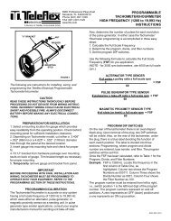
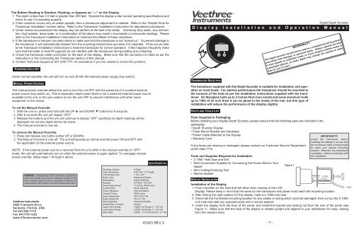
The Bottom Reading is Random, Flashing, or Appears as “---” on the Display.1. The depth is less than 2.5 feet or greater than 200 feet. Operate the display under normal operating specifications andcheck to see if it operating properly.2. If this condition occurs only at certain speeds, then a transducer adjustment is needed. Refer to the “Helpful Hints forTransducer Installation” section below. Refer to the Transducer Installation Instructions for adjustment procedures.3. Under certain circumstances the display may not perform at the best of its ability. Extremely dirty water, very soft bottom,high speeds, deep water, or a combination of the above may result in incomplete or inaccurate readings. Pleaserefer to the Transducer Installation Instructions to minimize the effects of these conditions.4. If the transducer is transom mounted check to make sure that the transducer is not “kicked-up”. To prevent damage tothe transducer, it will automatically release from the mounting bracket (kick-up) when it is impacted. If this occurs referto the Transducer Installation Instructions to reset the transducer for normal operation. If this happens frequently makesure that the trailer or boat lift supports do not interfere with the transducer during loading and unloading.5. Check the transducer cable connection on the back of the display. Make sure that the connection is made as per theinstructions in the Connecting the Transducer section of this manual.6. Contact Technical Support at 941-538-7775 for assistance if you are unable to correct the problem.POWERING ON & OFFUnder normal operation the unit will turn on and off with the external power supply (key switch).MANAUL POWER OVERIDEThe manual power override allows the user to turn the unit OFF with the presence of a constant externalpower source (key switch on). This is especially helpful when there is not a switched external power sourceavailable to the unit, or the user wishes to turn the unit OFF to prevent interference with other sonarequipment on the vessel.To set the Manual Override:1. With the unit on, press and hold both the UP andDOWNbuttons for 6 seconds.2. After 6 seconds the unit will display “OFF”.3. Release the buttons and the unit will continue to display “OFF” signifying no depth readings will bedisplayed nor will any depth alarms be active.4. The manual override is now set.To remove the Manual Override:1. Press and release any button (either UP or DOWN).2. The Manual Override is now off. The unit will operate as notmal and will power ON and OFF withthe application of the external power source.NOTE: If the external power source is removed from the unit while in the manual override or “OFF”mode, the unit will automatically turn on when the external power is again applied. To reengage manualpower override, follow steps 1 through 4 above.WARNING: Disassembly of the electronic componentswithin this display may result in exposure to lead in theform of solder, which is known to the state of California tocause cancer, birth defects, and other reproductive harm.<strong>Veethree</strong> <strong>Instruments</strong>2420 Trailmate DriveSarasota, Florida, USATel 941/538-7775Fax 941/755-1222www.V3instruments.comSpecificationsMounting LocationIn-DashCase Dimensions2.08" Dia, 1.75" <strong>Depth</strong>LCD Window Size 1.15" x 0.5"Button TypeWaterproof RubberBacklightingAmber SoftGlowReadout 2.5’-99.9’, 100’-200’Power Requirement11-14Vdc, 200mA maxCurrent Drain40mA, NominalUnits of MeasureFeet and MetersTransmit Power250W (max)<strong>Depth</strong> Range Max 200 Ft (60.7 M)<strong>Depth</strong> Range Min 2.5 Ft (.7 M)Alarm SignalingVisual and AudibleAudible Alarm Location InternalUpper Alarm Range 3-200ft, Full Range (1 - 60.7 M)Lower Alarm Range 3-200ft, Full Range (1 - 60.7 M)Keel Offset 0-20Ft, .1 Ft Increments (0 - 6.1 M)67423 REV 2<strong>Digital</strong> <strong>Depth</strong> SounderD i s p l a y I n s t a l l a t i o n a n d O p e r a t i o n M a n u a lT RANSDUCER S ELECTIONP ARTS AND T OOLS L ISTParts Supplied in PackagingBefore installing your display <strong>Depth</strong> Sounder, please ensure that the following parts are included in thepackaging:• <strong>Depth</strong> Sounder Display• Flush Mount Bracket and Hardware• Power Cable Attached to the Display• Warranty CardIf any items are missing or damaged, please contact our Customer Service Departmentat 941-538-7775Tools and Supplies Required for Installation• 2 1/8th” Hole Saw and Drill• Wire Connectors Suitable for Connecting the Power Wire to YourVessel• Wire Cutting/Crimping Tool• Marine SealantW A R N I N G !!!!T h i s d e p t h s o u n d e r s h o u l d n o t b e u s e d a s a n a v i g a t i o n a l a i d t o p r e v e n tg r o u n d i n g , b o a t d a m a g e , o r p e r s o n a l i n j u r y . A l w a y s o p e r a t e t h e b o a ta t s l o w s p e e d s i n u n f a m i l i a r w a t e r , o r i f y o u s u s p e c t s h a l l o w w a t e r o rs u b m e r g e d o b j e c t s , a s w a t e r d e p t h m a y c h a n g e t o o q u i c k l y t o a l l o wt i m e f o r y o u t o r e a c t .The transducer supplied with the <strong>Depth</strong> Sounder is suitable for installation and operationon most boats. For optimal performance the transducer should be mounted tothe transom of the boat as per the installation instructions supplied with the transducer.On fiberglass hulls up to 3 inches thick (non-cored) and some aluminum hullsup to 1/8th of an inch thick it can be glued to the inside of the hull, but this type ofinstallation will reduce the performance of the display slightly.D ISPLAY I NSTALLATIONFigure 1IMPORTANT!!!!Install the transducer beforeinstalling the display to ensure thatthe transducer cable is long enoughto reach your desired mountinglocation. Read ALL the instructionscompletely before proceeding withthe installation.Installation of the Display1. Find a location on the boat that will allow clear viewing of the LCDDisplay. Please keep in mind that the wires for the transducer and power must reach the mounting location.2. After finding the right location for the display, mark a 2 1/8th-inch hole.3. Check behind the desired mounting location for any cables or wiring which could be damaged, then cut out the 2 1/8thinchhole and seal any exposed wood with a marine sealant.4. Insert the display from the front of the panel, and install the bracket and locking nut from the rear of the panel (seeFigure 1). Make sure that the face of the display is rotated upright and aligned to your satisfaction for easy viewingfrom the vessel’s helm.- 1 -
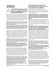
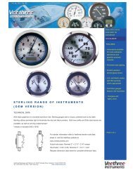
Wiring of the Power CableThe display has no ON/OFF switch. Therefore, you will need to wire it to apower source that will turn the display on as power is applied. The KeySwitch or an ON/OFF power switch will be suitable for powering the display.1. Connect the BLACK wire to the negative (-) battery terminal or suitableground (see Figure 2).2. Connect the RED wire to a positive (+) 12 Volt switchable power source(key switch, on/off switch) (see Figure 2).Connecting the Transducer CableTo connect the transducer cable to the display, align the plug from the transducerwith the plug from the display and press together as per figure Figure 3.O PERATING THE D ISPLAY- (black)Figure 2+ (red)Figure 3The display’s auto-ranging, auto-sensitivity features means that you never have to worry about adjustments. Simply turnthe power on, and your ready to go. The display emits sound signals that travel through water, and then calculates theamount of time that elapsed while the signal traveled down to the bottom and returned back to the transducer. This timeis calculated by the unit and displayed as a depth reading. Extremely dirty water, very soft bottom, high speeds, deepwater, or a combination of the above may result in incomplete or inaccurate readings. Under these conditions variablereadings or “- - -” (Figure 4) will be displayed.NOTICE!!!!All user selected settings will be retained when the power is turned off,therefore they will not need to be reset when the power is turned back on.Setting the Units of MeasureThe UNITS of measure for depth readout and alarm functions can be set in 4 easy steps. The two settingsavailable are Feet (FT) and Meters (M).To Set the Units:1. Press and hold the "UP" and "DOWN” keys at the same time for 5 seconds until the units indicator(FT or M) blinks (Figure 5).2. To set the units to FEET press the “UP” key. “FT” will flash on the Display.3. To set the units to METERS press the “DOWN” key. “M” will flash on the Display.4. The display will return to the normal operation mode automatically after five seconds.Setting the Shallow Water AlarmThe shallow alarm function can be set for depths ranging from 3 to 200 feet and triggers an alarmwhen the depth is less than the setting.To set the SHALLOW ALARM (upper alarm):1. Press the "UP" key located on the front of the display (Figure 6). The current alarm setting will bedisplayed on the display. "000" is the default setting.2. Pressing the "UP" key will increase the selected value. Pressing the "DOWN" key will reduce thevalue. Pressing and releasing the key will change the value in 1-foot increments per second.Holding down the key will change the value in 9 foot increments per second.3. After your selection is made, the display will return to normal operation after 5 seconds.4. The " "and " " icons will now be present.When triggered, the alarm sounds an audible "alarm" for ten seconds while flashing the warning LED and the " "and“ “ icons on the display. After 10 seconds the audible alarm mutes and the warning LED and the " " and " " iconscontinue to blink until the depth increases, or the alarm is reset. To reset the alarm repeat step 1 thru 4.Setting the Deep Water AlarmThe DEEP alarm function can be set for depths ranging from 3 to 200 feet and triggers an alarm whenthe depth is more than the setting.To set the DEEP ALARM (lower alarm):1. Press the "DOWN" key located on the front of the display (Figure 7). The current alarm settingwill be displayed on the display. "000" is the default setting.2. Pressing the "UP" key will increase the selected value. Pressing the "DOWN" key will reduce thevalue. Pressing and .- 2 -Figure 4Figure 5Figure 6Figure 7releasing the key will change the value in 1-foot increments per second. Holding down the key will change the value in9 foot increments per second.3. After your selection is made, the display will return to normal operation after 5 seconds.4. The " "and " " icons will now be presentWhen triggered, the alarm sounds an audible "alarm" for ten seconds while flashing the warning LED and the " "and“ “ icons on the display. After 10 seconds the audible alarm mutes and the warning LED and the " " and " " iconscontinue to blink until the depth increases, or the alarm is reset. To reset the alarm repeat step 1 thru 4.Setting the Keel OffsetThe Keel Offset feature is used to adjust the depth readings displayed by the display to compensatefor the depth of the water required for your vessel to operate safely.For Example: If your boat’s draft is 3 feet, the Keel Offset feature should be set to 3 feet. Thedisplay will then subtract 3 feet from the actual depth reading, and display this figure as the depth.If the water depth is 5 feet and the Keel Offset is set to 3 feet, the depth will be displayed as 2 feet,indicating to the operator that there is 2 feet of safe operating water.The maximum Keel Offset setting is 20 FT (6.1 M), settable in .1 (1/10 th ) Foot or Meter increments. The display will read“---” when a negative value occurs due to the Keel Offset Subtraction.To set the KEEL OFFSET:1. Press and hold the “UP” and “DOWN” keys at the same time for 3 seconds. When “K/O” begins flashing in the upperleft hand corner of the display, release the keys. (see figure 8). Press the "UP” key to increase the Keel Offset value. Press the "DOWN" key to reduce the value.3. The display will return to the normal operation mode after five seconds if no keys are pressed.4. “K/O” will remain illuminated in the top left hand corner indicating that the depth readings are adjusted to the Keel Offsetsetting.T ROUBLESHOOTINGWARNING!!!!If you are unsure of the Draft of your vessel, please consult with the vessel’smanufacturer before setting the Keel Offset. An improper Keel Offsetsetting can cause accidently grounding of the vessel and may causesevere damage to the vessel and it’s passengers.Figure 8There are no user repairable parts within the display. Attempting to repair the display yourself will only void the warranty.If you have a problem with your display, consult the following troubleshooting guide. If this does not remedy your problem,please contact Technical Support at 941-538-7775 for assistance.The display Does Not Turn On.1. Check the inline fuse located on the main power supply to the display. If it is blown, replace it with a 1 amp, normalblow fuse. Clean all corrosion from the fuse housing, and replace the fuse holder assembly if necessary.2. Check the power cable connection. Be sure that the display is connected to a known power source: RED wire to positive,BLACK wire to negative or ground.3. Ensure that the power source is powered using a test light, or some other reliable form of testing 12 volt power.4. If you are sure that the display is receiving power and is still not turning on, please refer to the warranty and servicesection.- 3 -