R100 Crescent receiver
R100 Crescent receiver
R100 Crescent receiver
- No tags were found...

Create successful ePaper yourself
Turn your PDF publications into a flip-book with our unique Google optimized e-Paper software.
CRESCENT <strong>R100</strong>User GuidePart Number 875-0173-000
COPYRIGHT NOTICEHemisphere GPS LLC Precision GPS Applications© Copyright Hemisphere GPS LLC (2006). All rights reserved.No part of this manual may be reproduced, transmitted, transcribed, stored in a retrievalsystem or translated into any language or computer language, in any form or by anymeans, electronic, mechanical, magnetic, optical, chemical, manual or otherwise, withoutthe prior written permission of Hemisphere GPS.TRADEMARKSHemisphere GPS and the Hemisphere GPS logo, Satloc and the Satloc logo, and CSIWireless and the CSI Wireless logo, Mapstar, Air Star Outback Guidance and eDrive aretrademarks of Hemisphere GPS, CSI Wireless, Inc. and CSI Wireless LLC. Othertrademarks are the properties of their respective owners.NOTICE TO CUSTOMERSContact your local dealer for technical assistance. To find the authorized dealer near you,call or write us at:Hemisphere GPS7560 East Redfield Road Telephone number: (480) 348-9919Suite B Fax number: (480) 348-6370Scottsdale, AZ 85260 E-mail address: sales@hemispherGPS.com
Warranty NoticeCOVERED PRODUCTSThis warranty covers all products manufactured by Hemisphere GPS LLC (the "Products").HEMISPHERE GPS LLC LIMITED WARRANTYHemisphere GPS LLC hereby warrants solely to the end purchaser of the Products, subject to the exclusions andprocedures set forth herein below, that the Products sold to such end purchaser shall be free, under normal use andmaintenance, from defects in material and workmanship for a period of 12 months from delivery to such endpurchaser. Repairs and replacement components are warranted, subject to the exclusions and procedures set forthbelow, to be free, under normal use and maintenance, from defects in material and workmanship for 90 days fromperformance or delivery, or for the balance of the original warranty period, whichever is greater.PURCHASER'S EXCLUSIVE REMEDYThe end purchaser's exclusive remedy under this warranty shall be limited to the repair or replacement, at theoption of Hemisphere GPS, of any defective Products or components thereof. The end user shall notify HemisphereGPS or a Hemisphere GPS approved service center immediately of any claimed defect. Repairs shall be madethrough a Hemisphere GPS approved service center only.EXCLUSIONSHemisphere GPS does not warrant damage occurring in transit or due to misuse, abuse, improper installation,neglect, lightning (or other electrical discharge) or fresh/salt water immersion of Products. Repair, modification orservice of Hemisphere GPS products by any party other than a Hemisphere GPS approved service center shall renderthis warranty null and void. Hemisphere GPS does not warrant claims asserted after the end of the warranty period.Hemisphere GPS does not warrant or guarantee the precision or accuracy of positions obtained when using Products.Products are not intended for primary navigation or for use in safety of life applications. The potential accuracy ofProducts as stated in Hemisphere GPS literature and/or Product specifications serves to provide only an estimate ofachievable accuracy based on:• Specifications provided by the US Department of Defense for GPS Positioning,• GPS OEM Receiver specifications of the appropriate manufacturer (if applicable), and• DGPS service provider performance specifications.Hemisphere GPS reserves the right to modify Products without any obligation to notify, supply or install anyimprovements or alterations to existing Products.NO OTHER WARRANTIESTHE FOREGOING WARRANTY IS EXCLUSIVE OF ALL OTHER WARRANTIES, WHETHER WRITTEN, ORAL, IMPLIED ORARISING BY STATUTE, COURSE OF DEALING OR TRADE USAGE, IN CONNECTION WITH THE DESIGN, SALE,INSTALLATION, SERVICE OR USE OF ANY PRODUCTS OR ANY COMPONENTS THEREOF, INCLUDING, BUT NOTLIMITED TO, ANY WARRANTY OF MERCHANTABILITY OR FITNESS FOR A PARTICULAR PURPOSE.LIMITATION OF LIABILITYTHE EXTENT OF HEMISPHERE GPS' LIABILITY FOR DAMAGES OF ANY NATURE TO THE END PURCHASER OR ANYOTHER PERSON OR ENTITY WHETHER IN CONTRACT OR TORT AND WHETHER TO PERSONS OR PROPERTY SHALL INNO CASE EXCEED, IN THE AGGREGATE, THE COST OF CORRECTING THE DEFECT IN THE PRODUCT OR, ATHEMISPHERE GPS' OPTION, THE COST OF REPLACING THE DEFECTIVE ITEM. IN NO EVENT WILL HEMISPHERE GPSBE LIABLE FOR ANY LOSS OF PRODUCTION, LOSS OF PROFITS, LOSS OF USE OR FOR ANY SPECIAL, INDIRECT,INCIDENTAL, CONSEQUENTIAL OR CONTINGENT DAMAGES, EVEN IF HEMISPHERE GPS HAS BEEN ADVISED OF THEPOSSIBILITY OF SUCH DAMAGES. WITHOUT LIMITING THE FOREGOING, HEMISPHERE GPS SHALL NOT BE LIABLEFOR ANY DAMAGES OF ANY KIND RESULTING FROM INSTALLATION, USE, QUALITY, PERFORMANCE OR ACCURACYOF ANY PRODUCTS.GOVERNING LEGISLATIONTo the greatest extent possible, this warranty shall be governed by the laws of the State of Arizona. In the event thatany provision hereof is held to be invalid by a court of competent jurisdiction, such provision shall be severed fromthis warranty and the remaining provisions shall remain in full force and effect.
OBTAINING WARRANTY SERVICEIn order to obtain warranty service, the end purchaser must bring the Product to a Hemisphere GPS approvedservice center along with the end purchaser's proof of purchase. For any questions regarding warranty service or toobtain information regarding the location of any of Hemisphere GPS' approved service centers, contact HemisphereGPS at the following address:Hemisphere LLC GPS7560 East Redfield Road, Suite BScottsdale, Arizona 85260Phone 480.348.9919 Fax 480.348.6370http://www.hemispheregps.com/main/
<strong>Crescent</strong> <strong>R100</strong> User GuideTable of Contents1: INSTALLATION . . . . . . . . . . . . .1Introduction . . . . . . . . . . . . . . . . . . . . . . . . . . . . . . . . . 2Features . . . . . . . . . . . . . . . . . . . . . . . . . . . . . . . . . . . . 3LED 3Menu system 3Installation . . . . . . . . . . . . . . . . . . . . . . . . . . . . . . . . . 18Cable interface 18Antenna and <strong>Crescent</strong> <strong>R100</strong> placement 19Powering the <strong>Crescent</strong> <strong>R100</strong> 19Connecting the <strong>Crescent</strong> <strong>R100</strong> to external devices . . . 22Factory parameters 23Installation 25Custom configuring the <strong>Crescent</strong> <strong>R100</strong> 25Environmental considerations 252: GPS OVERVIEW . . . . . . . . . . .27GPS Overview . . . . . . . . . . . . . . . . . . . . . . . . . . . . . . . 28GPS Operation 28Automatic Tracking 28Receiver Performance 28Differential Operation 29Automatic SBAS (WAAS, EGNOS, MSAS, etc) Tracking 29e-Dif 30i
1: INSTALLATIONIntroductionFeaturesMounting <strong>Crescent</strong> <strong>R100</strong>Connecting <strong>Crescent</strong> <strong>R100</strong> to External Devices
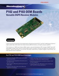
InstallationINTRODUCTIONCongratulations on buying Hemisphere GPS’ new <strong>Crescent</strong><strong>R100</strong>. The <strong>Crescent</strong> <strong>R100</strong> is a GPS <strong>receiver</strong> that tracks GPS andSBAS (WAAS and EGNOS). There are several varieties of the<strong>Crescent</strong> <strong>R100</strong> that also track DGPS radiobeacon signals and/orL-Band (OmniSTAR ® ). See Table 1-1 for a list of all the availablecombinations. All of the <strong>Crescent</strong> <strong>R100</strong> varieties utilize HemisphereGPS’ exclusive COAST technology during differential outages. The<strong>R100</strong> is also capable of using Hemisphere’s e-Dif technology.This provides you with sub-meter performance within 50centimeter accuracy 95% of the time. This chapter provides thefollowing information:• Features• Installation• Connecting to a power sourceNote: Any reference to the <strong>R100</strong> can be taken as any of thefollowing <strong>receiver</strong>s: <strong>R100</strong>, R110, R120 or R130. Anyreference to the beacon only applies to the R110 or R130.Any reference to OmniSTAR only applies to the R120 andR130.Table 1-1: Varieties of <strong>R100</strong>NameBeaconL-band(OmniSTAR)<strong>Crescent</strong> <strong>R100</strong> No No<strong>Crescent</strong> R110 Yes No<strong>Crescent</strong> R120 No Yes<strong>Crescent</strong> R130 Yes Yes2
<strong>Crescent</strong> <strong>R100</strong> User GuideFEATURESThe <strong>Crescent</strong> <strong>R100</strong> has several new features that will enhance youruser experience. The main differences over the <strong>R100</strong>’spredecessors are the LED’s and the menu system.LEDThe <strong>Crescent</strong> <strong>R100</strong> uses three LEDs. These LEDs function aredefined as:• Red: power indicator; this LED will illuminate when the<strong>R100</strong> is powered.• Yellow: GPS lock indicator; This LED will remainilluminated once the <strong>R100</strong> achieves a solid GPS lock.• Blinking Green: Differential lock indicator; This indicatorwill blink when the <strong>R100</strong> has achieved a solid SBAS,beacon, or OmniSTAR lock with better than a 150 bit errorrate (BER) or when it is successfully receiving externallyinput RTCM corrections.• Solid Green: DGPS position indicator; this LED will solidifywhen the <strong>receiver</strong> has achieved a differential position andthe pseudoorange residual of better than 10.0 meters. ifthe residual value is worse than the current threshold, thegreen LED will blink indicating that differential mode hasbeen attained, but that the residual has not met thethreshold.Menu systemThe menu system on the <strong>R100</strong> is designed for easy setup andconfiguration of the unit in the field or in the office. Mostconfigurations can be done entirely through the menu systemwithout having to connect to a computer or PDA. Figures 1-1 toFigure 1-10 provide a flow chart of the main menu system.3
InstallationLatitudeLongitudeHeightHeadingGPSPositionStatusVelocityDifferentialSV CountHorizontalDilution ofPrecisionFigure 1-1. Main Menu A4
<strong>Crescent</strong> <strong>R100</strong> User GuideRes rmsSigma-aSigma-bAzimuthGPSPositionStatus(continued)PrecisionStandardDeviationLatitudeStandarddeviationlongitudeStandarddeviationaltitudeFigure 1-2. Main Menu B5
InstallationCar SmoothEph ExistsEph HealthyNavCndNotUsed PrevGPS(Continued)PositionStatus(Continued)Above EleDiff CorrNo Diff CorrDSP:CarLockDSP:BERDSP:DSPLockDSP:FrmSyncDSP:TrkModeDSP-ARMARM:GPSLockAARM:DiffDataARM:ARMLockARM:DGPSARM:SolutnFigure 1-3. Main Menu C6
<strong>Crescent</strong> <strong>R100</strong> User GuideCHXX-SVXX ELXXXSatellitesAZXXX SNR XXGPS(Continued)Elev MaskMaxDGPSAgeConfigureData PORT AData PORT BUTC OffsetFigure 1-4. Main menu D7
InstallationEnter Name XXXDiffData PORT AConfigWizardProceedWizardCreate NewData PORT BElev MaskMaxDGPSAgePort APort BFigure 1-5. Main menu E8
<strong>Crescent</strong> <strong>R100</strong> User GuideSave toLocationCreate New(Continued)Save toLocationNot Used1Not Used2Not Used3Not Used4ProceedWizard(Continued)Not Used5Save toLocationSave CurrentEnter NameNot Used1Not Used2Not Used3Not Used4Not Used5Figure 1-6. Main menu F9
InstallationNot Used1Not Used2Delete SavedNot Used3Not Used4Not Used5ConfigWizard(Continued)Not Used1Not Used2Use PreviousNot Used3Not Used4CancelNot USed5Figure 1-7. Main menu G10
<strong>Crescent</strong> <strong>R100</strong> User GuideIn-UseDisplay AppsOtherSwapApplicationsDisplay UpdateSystemSetupDisplay FormatLL UnitHgt UnitVel UnitBaud RatesPORT APORT BFigure 1-8. Main menu H11
InstallationGGAGLLGSAGSTGSVHDTSystemSetup(Continued)Display LogsHPRRMCROTRREVTGZDABin1Bin2Bin80Bin93Figure 1-9. Main menu I12
<strong>Crescent</strong> <strong>R100</strong> User GuideBin94Bin95Bin96Bin97Bin98Bin99RTCMDisplays Logs(Continued)RD1PCSI,1SystemSetup(Continued)Software DispMenu System<strong>Crescent</strong>AppS/NSBXContrastAnimationReceiverSubscriptionFigure 1-10. Main menu J13
InstallationFigure 1-11 to Figure 1-15 provides a flowchart for the differentialmenus.RTCM Portl-DifRTCM BaudLtLnBaseStationReferenceHgtSet ReferenceUse Current PosRTCM PortExternRTCMRTCM BaudDiffFigure 1-11. Differential menu A14
<strong>Crescent</strong> <strong>R100</strong> User GuideBERBERLnSignal StatusLnElevElevAzAzModeSBASSatellitesPRNPRNDiffFigure1-12. Differential menu B15
InstallationFSS SNRBeaconSignal StatusMPT % QUnselected BxID HFigure 1-13. Differential menu CTuneAfricaAsiaBeacon(Continued)ConfigureDiffAuto TuneTuneBeaconNameAustraliaCentral AmericaEuropeNorth AmericaSouth AmericaFigure 1-14. Differential menu D16
<strong>Crescent</strong> <strong>R100</strong> User GuideAutonomousNo Dif SourceDiffModeStatuse-DifRecalibrateAge of DiffDiffFigure 1-15. Differential menu E17
InstallationINSTALLATIONCable interfaceThe power cable is unterminated for easy integration into anysystem and must reach an appropriate power source. The dataconnector (DB9) communication port must reach to connect to adata storage device, computer or other device that accepts GPSdata.When choosing a route for all of the <strong>Crescent</strong> <strong>R100</strong> cables:• Avoid running cables in areas of excessive heat• Keep cables away from corrosive chemicals• Do not run the extension cable through door or windowjams• Keep the cables away from rotating machinery• Do not bend excessively or crimp the cables• Avoid placing tension on the cables• Remove unwanted slack from the extension cable at the<strong>receiver</strong> end• Secure along the cable route using plastic wrapsWarning!Improperly installed cables near machinery can bedangerous.18
<strong>Crescent</strong> <strong>R100</strong> User GuideAntenna and <strong>Crescent</strong> <strong>R100</strong> placementPlacement of the antenna that comes with the <strong>R100</strong> is crucial tothe system’s operation. The GPS engine inside the <strong>Crescent</strong> <strong>R100</strong>computes a position based upon measurements from each satelliteto the center of the antenna. Mount the antenna at a location atwhich you would like to reference your position. Make certain thatthere is an unobstructed view of the sky available when choosing alocation to mount the antenna. This will ensure that GPS satellitesare not masked by obstructions, potentially reducing systemperformance.Mount the <strong>R100</strong> unit inside the vehicle, away from the elementsand in a location that minimizes vibration, shock, extremetemperatures and moisture.Powering the <strong>Crescent</strong> <strong>R100</strong>To power the <strong>Crescent</strong> <strong>R100</strong>:1. Connect the unterminated ends of the <strong>Crescent</strong> <strong>R100</strong> powercable to a clean power source providing between 8 and36 VDC.2. Turn on the system by applying power to it and pressing thethe on/off switch on the back panel. The <strong>Crescent</strong> <strong>R100</strong>accepts an input voltage between 8-36 VDC via the powercable. For best performance, the supplied power should be19
Installationcontinuous and clean. Table B-1 in the Appendix provides thepower specifications of the <strong>Crescent</strong> <strong>R100</strong> smart antenna. A3.0 A quick-blow fuse is situated in-line of the power cable. Thefuse protects the <strong>Crescent</strong> <strong>R100</strong> from power surges. The fusecontainer should remain accessible after installation.Note: We suggest that a weather-tight connection andconnector be used if the connection will be located outside.Warning!Be careful not to provide a voltage higher than the inputrange (36 VDC). This will damage the <strong>receiver</strong> and will voidthe warranty.Warning!Do not attempt to operate the <strong>Crescent</strong> <strong>R100</strong> with the fusebypassed. Such a modification will void the productwarranty.The <strong>Crescent</strong> <strong>R100</strong> features reverse polarity protection toprevent damage if the power leads are accidentally reversed.With the application of power, the <strong>Crescent</strong> <strong>R100</strong> will proceedthrough an internal start-up sequence, however it will be readyto communicate immediately.Note: The first start-up can take from 5 to 15 minutesdepending on your location. The <strong>receiver</strong> will lock within1 to 5 minutes once the <strong>receiver</strong> has an updated almanacfor the first time. This may vary depending where you are inthe world.20
<strong>Crescent</strong> <strong>R100</strong> User GuideNote: The <strong>Crescent</strong> <strong>R100</strong> can take up to five minutes for afull ionoshperic map to be received from WAAS. Optimumaccuracy will be obtained once the <strong>Crescent</strong> <strong>R100</strong> isprocessing corrected positions using complete ionosphericinformation.21
InstallationCONNECTING THE CRESCENT <strong>R100</strong>TO EXTERNAL DEVICESThe serial ports of the <strong>Crescent</strong> <strong>R100</strong> operate at the RS-232Cinterface level to communicate with external data loggers,navigation systems and other devices. The two serial ports areaccessible via the back panel and are both DB9 female connectors.The serial port is also used for firmware updates. Figure 1-2displays the numbering for the power cable’s DB9 connector(female). The associated numbering for the plug connector (male)is a mirror reflection of the scheme shown in figure 1-2.Figure 1-16. DB9 socket numberingNote: For successful communication, the baud rate of the<strong>Crescent</strong> <strong>R100</strong> serial ports must be set to match that of thedevices to which they are connected. Table 1-2 and 1-3, onpages 24 and 25, provides the pin configuration for the serialports.22
<strong>Crescent</strong> <strong>R100</strong> User GuideFactory parametersTables 1-2 to 1-5 identify the default <strong>Crescent</strong> <strong>R100</strong> configuration.Table 1-2: Port A pin-out , DB9 connector pinnumber descriptionPinFunction1 Not Connected2 Transmit data Port A3 Receive data Port A4 Not connected5 Signal ground6 Event marker7 Not connected8 Not connected9 1 PPSTable 1-3: Port B pin-out, DB9 connector pinnumber descriptionPinFunction1 Not connected2 Transmit data Port B3 Receive data Port B4 Not connected5 Signal ground6 Not connected7 Not connected23
InstallationTable 1-3: Port B pin-out, DB9 connector pinnumber descriptionPinFunction8 Not connected9 Not connectedTable 1-4: DGPSWAAS (default)e-DifBeacon (only on R110and R130)Table 1-5: Serial port settingsSerialportBaudrateDatabitsParityStopbitInterfacelevelSerial portA and B480096001920038400576008 None 1 R2-232CTable 1-6: GPS message output optionsGPS messageUpdaterateMax DGPS ageElevationmaskHemisphere GPSBinaryFrom 1 Hzto 20 Hz259,200seconds5°24
<strong>Crescent</strong> <strong>R100</strong> User GuideInstallationThe <strong>Crescent</strong> <strong>R100</strong> features two serial ports. The ports handlescommunication to and from the <strong>Crescent</strong> <strong>R100</strong>. The ports may beconfigured for a mixture of NMEA 0183, binary and RTCM SC-104data. The usual data output is only various NMEA 0183 datamessages.Custom configuring the <strong>Crescent</strong> <strong>R100</strong>All aspects of the <strong>Crescent</strong> <strong>R100</strong> may be configured through theserial port with the use of Hemisphere GPS commands. You canconfigure the following items:• Selecting one of the two on-board applications• Selecting the baud rate• Choosing which NMEA 0183 data message to output on thedual serial ports and the update rate of each messageEnvironmental considerationsThe <strong>Crescent</strong> <strong>R100</strong> is designed to be used indoors, it is howeversplash proof in case of accidental exposure. The antenna isdesigned to be used outdoors. See table B-4 in the Appendix forthe environmental specifications.Note: The changes you make to the <strong>Crescent</strong> <strong>R100</strong> will notbe saved to the memory for subsequent power-up unless asave command is issued ($JSAVE).Note: Contact your local Hemisphere GPS dealer for moreinformation regarding the use of Hemisphere GPScommands and customized configuration.25
2: GPS OVERVIEWGPS OperationAutomatic TrackingReceiver PerformanceDifferential OperationAutomatic SBAS Trackinge-Dif
InstallationGPS OVERVIEWThis chapter describes the various modes of operation and featuresof your <strong>Crescent</strong> <strong>R100</strong> <strong>receiver</strong> and internal sensors. For yourconvenience, both the GPS and differential correction of the<strong>Crescent</strong> <strong>R100</strong> are pre-configured. The <strong>receiver</strong> will work out of thebox, and for most applications, little user set up is necessary.When powered for the first time, the <strong>Crescent</strong> <strong>R100</strong> will perform a“cold start,” which involves acquiring the available GPS satellites inview and the WAAS/EGNOS differential service.GPS OperationThe GPS engine is always operating, regardless of the DGPS modeof operation. The following sections describe the general operationof the <strong>Crescent</strong> <strong>R100</strong>’s internal GPS engine.Automatic TrackingThe GPS engine within the <strong>Crescent</strong> <strong>R100</strong> automatically searchesfor GPS satellites, acquires the signals and manages the navigationinformation required for positioning and tracking. This is ahands-free mode of operation.Receiver PerformanceThe <strong>Crescent</strong> <strong>R100</strong> works by finding 4 or more GPS satellites in thevisible sky and uses the information those satellites provide tocompute an appropriate position (within 5 meters). Since there issome error in the GPS data calculations, the <strong>Crescent</strong> <strong>R100</strong> alsotracks a differential correction. The <strong>Crescent</strong> <strong>R100</strong> uses thesecorrections to improve its position to less than 1 meter.28
<strong>Crescent</strong> <strong>R100</strong> User GuideThere are two main aspects of GPS <strong>receiver</strong> performance:• Positioning• Satellite acquisition qualityWhen the <strong>Crescent</strong> <strong>R100</strong> is properly positioned on your vehicle, thesatellites transmit coded information to the antenna on a specificfrequency that allows the <strong>receiver</strong> to calculate a range to eachsatellite. GPS is essentially a timing system. The ranges arecalculated by timing how long it takes for the GPS signal to reachthe GPS antenna. To calculate the geographic location, the GPS<strong>receiver</strong> uses a complex algorithm incorporating satellite locationsand ranges to each satellite. Reception of any four or more of thesesignals allows a GPS <strong>receiver</strong> to compute 3-dimensionalcoordinates.Differential OperationThe Radio Technical Commission of Marine services (RTCM) has adifferential service intended for correction services. This includesWide Area Augmentation System (WAAS) and other compatibleSpace Based Augmentation Systems (SBAS), such as the EuropeanGeo-stationary Navigation Overlay System (EGNOS). The <strong>Crescent</strong><strong>R100</strong> is compatible with each of these differential services inaddition to Hemisphere GPS’s patented e-Dif.Automatic SBAS (WAAS, EGNOS, MSAS, etc) TrackingThe <strong>Crescent</strong> <strong>R100</strong> will automatically scan and track the satellitesignals. This automatic tracking allows you to focus on otheraspects of differential operation without the need to tune the<strong>receiver</strong>. The <strong>Crescent</strong> <strong>R100</strong> features two-channel SBAS trackingthat provides an enhanced ability to maintain a lock on a SBASsatellite when more than one satellite is in view. This redundanttracking approach results in more consistent tracking of a SBASsignal when in an area where signal blockage of a satellite ispossible.29
Installatione-DifA <strong>Crescent</strong> <strong>R100</strong> that is equipped with Hemisphere’s e-Difcapabilities can operate anywhere in the world where normal GPSsignals can be viewed. e-Dif is only available with a specialsubscription code. Hemisphere developed e-Dif for our customerswho are not able to receive other types of differential signals due tolocation or budget. e-Dif requires a subscription. Once theHemisphere e-Dif capable <strong>Crescent</strong> <strong>R100</strong> computes a differentialcorrection, the user can operate for up to 40 minutes beforeneeding to go back to a reference position and updating thedifferential correctors. During this 40 minutes, e-Dif’s positionaccuracy is typically within 2 meters (6 feet), relative to theoriginal location.30
APPENDIXTroubleshooting<strong>Crescent</strong> <strong>R100</strong> SpecificationsNetworkAccessories
InstallationA: TroubleshootingTable A-1 provides a checklist to troubleshoot common problemsand their solutions for the <strong>Crescent</strong> <strong>R100</strong>.Table A-1: TroubleshootingProblemReceiver fails topowerPossible solution• Verify polarity of power leads• Check integrity of power cableconnections• Check power input voltage(8 - 36 VDC)• Check current restrictions imposedby power source (maximum is250 mA @12 VDC)No data from<strong>Crescent</strong> <strong>R100</strong>• Check <strong>receiver</strong> power status(red LED)• Check integrity and connectivity ofpower and data cable connections• The volume of data requested to beoutput by the <strong>Crescent</strong> <strong>R100</strong> couldbe higher than what the currentbaud rate supports. Try using19,200, or higher, as the baud ratefor all devices.No GPS lock • Check integrity of cable connections• Verify <strong>Crescent</strong> <strong>R100</strong>’s unobstructedview of the sky32
<strong>Crescent</strong> <strong>R100</strong> User GuideTable A-1: TroubleshootingProblemPossible solutionNo SBAS lock • Check integrity of cable connections• Verify <strong>Crescent</strong> <strong>R100</strong>’s unobstructedview of the sky• Check SBAS visibility map33
InstallationB: <strong>Crescent</strong> <strong>R100</strong> SpecificationsTable B-1 to B-5 provides the power, mechanical, communication,environmental and DGPS specifications for the <strong>Crescent</strong> <strong>R100</strong>.Table B-1: Power specificationsItemInput voltagePower consumptionCurrent ConsumptionSpecification8 - 36 VDC< 3 W @ 12 VDC (typical)250 mA @ 12 VDC (typical)Table B-2: Mechanical specificationsItemHeightWidthLengthWeightSpecification46.4 mm (1.8 in)119.4 mm (4.7 in)258.6 mm (6.3 in)0.56 kg (1.23 lbs)Table B-3: Communication specificationsItemSerial portsPulse outputDescription2 full duplex RS2321 PPS (HCMOS, active high, risingedge sync)Baud rates 4800 - 57600Differential correctionI/O protocolRTCM SC-10434
<strong>Crescent</strong> <strong>R100</strong> User GuideTable B-3: Communication specificationsData I/O protocolGround speed outputEvent mark outputNMEA 0183 and SLX binaryRange: 0.8 - >322 Km/h(0.5 - >200 mph)Signal: Opto-isolated pulse outFrequency Conversion: 94 Hz/m/s(28.65 pulse per foot traveled)HCMOS, active low, falling edgesync, 10 k-ohm, 10 pF loadTable B-4: Environmental specificationsItemOperating temperatureStorage temperatureHumiditySpecification-30° C to +70° C(-22° F to + 158° F)-40° C to +85° C(-40° F to + 185° F)95%, non condensingTable B-5: GPS sensor specificationsItemReceiver typeChannelsUpdate rateSpecificationL1, C/A code with carrier phasesmoothing (Patented COASTtechnology during differential signaloutage)12-channel, parallel tracking(10-channel when tracking SBAS)1 - 20 Hz35
InstallationTable B-5: GPS sensor specificationsHorizontal accuracy • < 0.6 m 95% confidence(DGPS) *• < 2.5 m 95% confidence(autonomous) **Differential OptionsSBAS TrackingStart up timeSatellite ReaquisitionSBAS, e-Dif, L-Dif, and radio beacon2-channel, parallel tracking60 s (no almanac and RTC)< 1 s* Depends on multipath environment, number of satellites in view,satellite geometry, baseline length (for local services) andionospheric activity**Depends on multipath environment, number of satellites in view,satellite geometry and ionospheric activity.36
<strong>Crescent</strong> <strong>R100</strong> User GuideC: <strong>Crescent</strong> <strong>R100</strong> AccessoriesTable C-1 provides the available accessories for the <strong>Crescent</strong> <strong>R100</strong>.Table C-1: <strong>Crescent</strong> <strong>R100</strong> Part accessoriesPart NumberAccessories050-0011-022# Data cable052-0005-000# Antenna cable, 5 m (16.4 ft)054-0009-000 Power cable (unterminated)600-1021-000# Threaded adapter (5/8” to 1”)602-1005-000 Mounting brackets725-0007-014 Magnetic mount803-0037-000 <strong>Crescent</strong> <strong>R100</strong>804-0023-000 CDA-3RTK875-0173-000 <strong>Crescent</strong> <strong>R100</strong> user guideVarious screws and nuts37
© 2005 Hemisphere GPSwww.hemispheregps.come-mail: info@hemispheregps.com