Valtek Severe Service Equipment
Valtek Severe Service Equipment
Valtek Severe Service Equipment
- No tags were found...

You also want an ePaper? Increase the reach of your titles
YUMPU automatically turns print PDFs into web optimized ePapers that Google loves.
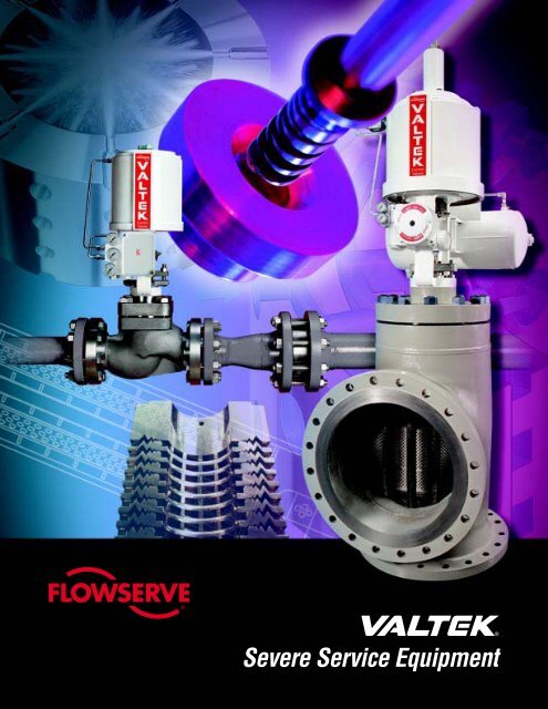
<strong>Severe</strong> <strong>Service</strong> <strong>Equipment</strong>
<strong>Valtek</strong> <strong>Severe</strong> <strong>Service</strong> <strong>Equipment</strong>IntroductionPressure/Velocity Profiles in Globe ValvesAs a fluid travels through a conventional single-seatedglobe-style control valve, a vena contracta (point of narrowestflow restriction) develops directly downstreamof the throttling point. At this location of maximumvelocity, the fluid reaches a minimum pressure and thenrapidy recovers to a level less than the inlet pressure(Figure 1). Profiles representative of the pressure andvelocity in a gaseous application are shown in Figure 2.P 1P 2P(ValvePressureDrop)(Velocity atVena Contracta)P VC(Outlet Pressure)(Pressure atVena Contracta)Pressure Profile Single SeatFigure 1: Pressure Profile(single-seated globe-style valve)V 1V VCV 2P 1P 2Gaseous NoiseP VCFigure 2: Pressure and Velocity Profiles(single-seated globe-style valve)LIQUID SEVERE SERVICESWhen control valves fail in liquid service, cavitation isoften the root cause. Cavitation is a two-stage process,illustrated in Figure 3: First, as fluid velocity increasesthrough the restriction at the vena contracta, the pressureof the flowing liquid drops below the vapor pressureof the liquid, causing vapor bubbles to form. Second, asthe flow enters the enlarged flow area downstream of thevena contracta the fluid pressure increases. The result-ant pressure recovery raises the fluid pressure backabove the vapor pressure, causing the vapor bubbles tocollapse – or implode.Energy released by collapsing vapor bubbles can resultin extensive noise and vibration, often causing severedamage to unprotected metal surfaces (Figure 4).P 1P 2Cavitation in LiquidsP VCP V (VaporPressure)Figure 3: Pressure Profile for CavitationFigure 4: Damage to Trim Parts Causedby Cavitation2Flowserve Corporation, <strong>Valtek</strong> Control Products, Tel. USA 801 489 8611
<strong>Valtek</strong> <strong>Severe</strong> <strong>Service</strong> <strong>Equipment</strong>IntroductionIncipient (or beginning) cavitation is heard in a pipingsystem as intermittent popping or cracking, but as thepressure drop increases the noise becomes a steadyhiss or rattle. Fully developed cavitation results in chokingof the liquid flow such that further increases inpressure drop cause no corresponding increase in theflow.The ideal solution to cavitation is to reduce the pressurefrom inlet to outlet gradually, avoiding the effects of alarge pressure drop at the vena contracta (Figure 5).P1P 2V 1V 2P V (VaporPressure)Figure 5: Pressure Profile for GradualPressure ReductionCavitation can be avoided entirely by not permitting thepressure to fall below the vapor pressure, thereby eliminatingany bubble formation and subsequent collapse.A related liquid service problem is flashing, which occurswhen pressure at the vena contracta falls below thevapor pressure followed by a pressure recovery thatremains below the vapor pressure (Figure 6). Thiscauses vapor bubbles to form in the liquid service,which continue downstream as a liquid-gas mixture.The increased volume of this mixture increases theoverall velocity, which leads to excessive noise anderosion. Eliminating flashing completely is generally notpractical and would involve increasing the valve downstreampressure or lowering the vapor pressure of theprocess. More practical approaches include using hardenedmaterials for affected surfaces, or relocating thevalve so that it discharges into a larger vessel and awayfrom critical surfaces.Sigma: The Cavitation IndexVarious cavitation indices have been used to correlateperformance data to improve designs of hydraulic processequipment. A cavitation index, called Sigma (σ),has been developed and applied to quantify cavitation incontrol valves:σ = (P - P ) 1 v(P 1- P 2)Where:P 1= Upstream pressure (psia), measured two pipediameters upstream from the valveP 2= Downstream pressure (psia), measured six pipediameters downstream from the valveP V= Vapor pressure of the liquid at flowingtemperatureSigma is seen as the ratio of the potential for resistingcavity formation to the potential for causing cavity formation.When Sigma is 1.0 or less, flashing is occurring.Through laboratory and field testing results, acceptableoperating Sigmas for eliminating cavitation (and itsassociated choking, noise, and damage) have beenestablished. For example:Tests indicate that a full-area, single-seated globe valveat 100 percent open with 80° F (vapor pressure of 0.5psia), 200 psia water and with flow-over-the-plug chokesat a downstream pressure of 56 psia. The chokedcavitation index is then:P 1P 2P VCP V(VaporPressure)Figure 6: Pressure Profile for Flashings choked= (200 - 0.5) = 1.39(200 - 56)These tests also indicate that cavitation damage (s damage)for this particular style of valve in continuous operationbegins at about s damage= 1.73. The point at whichincipient cavitation (s incipient) occurs can also be deducedfrom tests; it is found at a somewhat higher value thans damage(i.e. lower pressure drop).Flowserve Corporation, <strong>Valtek</strong> Control Products, Tel. USA 801 489 86113
<strong>Valtek</strong> <strong>Severe</strong> <strong>Service</strong> <strong>Equipment</strong>IntroductionIf this same valve operates wide open at an upstreampressure (P 1) of 500 psia and a downstream pressure(P 2) of 200 psia, and the water temperature increasedto 180° F (vapor pressure = 7.5 psia), the operatingSigma is:σ operating= (500 - 7.5) = 1.64(500 - 200)Because this Sigma value is greater than σ choked, thevalve is not choked at these conditions. However, theSigma is less than σ damage; therefore, the valve mayexperience cavitation damage unless special anticavitationtrim or harder materials are used.Some of the other factors that affect the intensity ofcavitation are the magnitude of the actual service pres-sure compared with test pressures, the flow path geometryand the fluid purity. By researching these factors,methods of scaling the index for such variables havebeen established. This geometry and pressure scalingis not accounted for in the use of liquid pressure recoveryfactor (F L) and liquid cavitation factor (F i) in previousvalve sizing equations.Globe valves experience minimal cavitation damagewhen operating at low pressure (Sigmas between 2and 1.7). Generally, in these cases, no cavitation controltrim is necessary. However, at between Sigma 1.7 and1.15, some cavitation control is usually required. Whenthe Sigma index for a valve is less than 1.15, thepotential for severe cavitation damage exists and astaged pressure drop severe service trim must beincluded in the valve’s sizing.Table 1: <strong>Valtek</strong> Trim Solutions to Cavitation Associated with Control ValvesGlobe-styleTrimTiger-ToothChannelStreamMicroCavCavControlDesignStackof expanding teeth discsCartridge or plug with cylindersusing intersecting channelsPlugwith expansion groovesDiametricallyopposed jetsTo eliminateformationApplicationor minimize cavitationTo eliminate or minimize cavitationformationTo eliminate or minimize cavitationformation in low flow servicesForSigmasapproaching1.002SeePages6 - 91.00210 - 141.00415Toeliminate or minimize cavitation damage1.1516 - 18GASEOUS SEVERE SERVICESIn gas services, noise is generated by high pressuredrops across the valve and by subsequent turbulencedownstream. As a direct result, noise is radiated to thesurrounding area by the downstream piping system(Figure 7). In situations where equipment damage orpersonal injury could be caused by a noise source, noiseattenuation is not only desired, it is mandatory.With gases, superimposing a velocity profile on thepressure profile (Figure 2) reveals the main componentin control valve noise generation. For single throttlingpoint control valves, because of the sharp pressurereduction at the vena contracta, the velocity is greatlyincreased. Tests have demonstrated that a control valve’ssound pressure level increases proportional to the velocitycubed (SPL ~ V 3 ). Noise is generated as velocitiesin the valve increase and substantial noise can begenerated even where velocities are significantly lessthan sonic.OSFigure 7: Downstream Turbulence Causedby Vena Contracta in a Valve4Flowserve Corporation, <strong>Valtek</strong> Control Products, Tel. USA 801 489 8611
<strong>Valtek</strong> <strong>Severe</strong> <strong>Service</strong> <strong>Equipment</strong>IntroductionHigh mechanical vibration levels accompany high acousticnoise levels. Acoustic noise and mechanical vibrationlevels are greatly compounded (up to 50 times) when thefrequency of the excitation matches acoustic and/ormechanical natural frequencies of the system.Noise suppression trim (source treatment) shouldalways be considered in any high energy (high pressure,high flow) and/or resonant noise/vibration applications.The solution to high levels of control valve noise is toreduce the pressure from the valve inlet to outlet gradually,avoiding the effects of a large pressure drop at anyvena contracta (Figure 5). Thus, for gases, velocities aremaintained at acceptable levels throughout the valveand high noise levels are not generated. This requiresnot only controlling the gas velocity through the valvetrim but at all points from the inlet to the outlet of thevalve.Several of the following factors must be consideredbefore expensive noise suppression equipment is chosen:How much noise attenuation is actually required?What are the low or no-cost alternatives to noise attenuation?If noise attenuation devices are necessary, whatlower-cost equipment can be specified?If the predicted sound pressure level (SPL) exceeds 85or 90 dBA, noise suppression devices should be considered.However, higher noise levels may be acceptableif the noise is not associated with equipmentdamage and is located in a remote location away frompeople. Other possible low-cost alternatives to noisesuppression equipment are: (1) insulating the pipe, (2)locating the valve discharge directly into a vessel (allowingthe noise to be absorbed by the vessel), (3) relocatingthe noise source (such as the downstream piping)outside an enclosed area, (4) reversing the flow directionthrough the valve, or (5) reducing the pressure dropacross the valve.The P 1/P 2Ratio IndexWhen excessive sound pressure levels are encountered,special trim must be used to attenuate the noise level.<strong>Valtek</strong> severe service trim can be installed in globe- andangle-style control valves for use in noise reduction andshould be used when a maximum sound attenuationof up to 30 dBA is needed. To establish the designrequirements for such trim, Flowserve engineers use aP 1/P 2ratio, along with other factors, to determine theseverity of noise in an application. To obtain the maximumnoise reduction for any trim, the service P 1/P 2ratiomust be less than the maximum P 1/P 2ratio listed foreach trim design and size. These ratios can be foundin the tables for each noise attenuating trim describedin this literature.Table 2: Flowserve Solutions to Gaseous Noise Associated with ValvesGlobe-style Trim /Downstream DeviceDesignSPL ReductionSee PagesTiger-ToothTrimMegaStream TrimExpandingteethMulti-holetrimUpto 30 dBA4 - 7Upto 28 dBA19 - 251MegaStream Plate Downstream multi-hole resistance plate1MegaStream Diffuser Downstream multi-hole diffuser1MegaStream Silencer Downstream In-line silencerUpto 15 dBA26 - 27Upto 15 dBA28 - 29Upto 30 dBA30 - 31Tiger-ToothVent ElementExpandingteeth ventUpto 30 dBA321Any one of these downstream noise reduction devices in series with a valve can be selected to attenuate noise to the acceptableSPL required. For example, a MegaStream plate or diffuser, when installed downstream from a standard <strong>Valtek</strong> control valve,provides about the same dBA reduction as a one or two-stage MegaStream valve, but at a lower cost. For extremely highpressure drops where multi-stage valve trim may be considered, a cost-effective option may be to install a MegaStream plate,diffuser or silencer downstream from a smaller one or two-stage MegaStream valve.Flowserve Corporation, <strong>Valtek</strong> Control Products, Tel. USA 801 489 86115
<strong>Valtek</strong> <strong>Severe</strong> <strong>Service</strong> <strong>Equipment</strong>Tiger-Tooth TrimIntroductionWhen installed in a globe-style control valve, Tiger-Tooth trim effectively reduces sound pressure levels upto 30 dBA. Tiger-Tooth trim can also be used to eliminatethe damaging effects of cavitation – making it an effectivechoice for either gas or liquid processes with highpressure drop conditions.DesignA cross-sectioned view of the Tiger-Tooth control valvestack is shown in Figure 8. The basic Tiger-Tooth designinvolves highly engineered concentric grooves (or teeth)machined into the face and backside of a series ofcircular stacked discs (called a stack), which also acts asa seat retainer. Legs separate one disc from another,providing the correct distance between individual discs.For easy assembly, the entire stack is tack-welded intoone concentric unit and clamped in a conventional globeor angle body valve.With Tiger-Tooth trim, flow passes from the center of thestack through the teeth in a radial, wave-like manner tothe outlet, undergoing a series of sudden contractionsand expansions. This process reduces fluid pressure insteps without the large, single pressure drop typical ofconventional trims.<strong>Valtek</strong> control valves with Tiger-Tooth trim are manufacturedin sizes 1.5 through 36-inch, utilizing conventional<strong>Valtek</strong> globe-style bodies. Both unbalanced and pressure-balanceddesigns are available (Figures 9 and 10).For smaller parts inventory and lower cost, many partsare interchangeable with conventional <strong>Valtek</strong> Mark Oneglobe valves. To minimize costs associated with largeglobe valve bodies, valves in sizes 16 through 36-inchmay be custom-fabricated using an angle body configurationwith the inlet at the bottom and the outlet on theside. For applications requiring long strokes, specialpneumatic cylinder, hydraulic or electric actuators areavailable.Figure 9: Unbalanced Tiger-ToothTrim DesignFigure 8: Tiger-Tooth Stack Featuring aFive-tooth DesignFigure 10: Pressure-balanced Tiger-ToothTrim Design6Flowserve Corporation, <strong>Valtek</strong> Control Products, Tel. USA 801 489 8611
<strong>Valtek</strong> <strong>Severe</strong> <strong>Service</strong> <strong>Equipment</strong>Tiger-Tooth TrimGas ApplicationsWith gases, the Tiger-Tooth design features a uniqueflow path that permits radial expansion of the fluid. Thetrim is effective on large pressure reductions in gases,because an additional flow path expansion is providedto handle the increasing volume as the pressure isdecreased. This is accomplished by making each toothand resulting flowpath somewhat larger than the precedingtooth. The increased flow area maintains acceptablegas velocity at every point across the discs.Liquid ApplicationsWith Tiger-Tooth trim, a series of small, multiple pressuredrops prevent cavitation from occurring at any pointinside the valve. The amount of pressure drop that canbe taken without cavitation occurring is proportional tothe difference between the local static pressure andvapor pressure. The expanding Tiger-Tooth design isused with liquids to eliminate most of the pressure dropas the flow first enters the trim. Because the fluid flowsunder the plug, the smaller teeth in any passage areencountered first, resulting in a higher pressure drop. Asthe fluid progresses through the stack, the expandingtooth pattern allows the pressure to be reduced in aseries of successively smaller pressure drops withoutexcursions below the vapor pressure – avoiding theformation of cavitation altogether.Velocity ControlOne of the fundamental design considerations with<strong>Valtek</strong> control valves with Tiger-Tooth trim is the establishmentof acceptable velocities at every point as theflow passes through the valve. For liquid applications,maintaining valve outlet velocities below 30 feet persecond is desirable – although higher velocities maybe acceptable depending upon the application andprocess fluid.For gaseous control valve applications, keeping themaximum outlet gas velocity below 0.33 Mach is desirable,although higher velocities may be acceptablebased on the application.Velocities must be assessed for the most difficult flowingconditions at the following critical points (as shown inFigure 11):1. The inlet passageway to the valve2. The internal flow area of the Tiger-Tooth stack at allplug positions3. The flow area between the teeth, including inlet andoutlet area of the stack342FLOWFigure 11: Tiger-Tooth Velocity Check Points4. The gallery flow area formed between the outsidediameter of the Tiger-Tooth stack and the insidediameter of the valve body5. Outlet passage flow areaPressure Reduction Through SuddenExpansion and ContractionAn important mechanism acting to reduce the pressurein Tiger-Tooth trim is the sudden expansion and contractionphenomenon that takes place as the flow passesover the teeth. Figure 12 illustrates this mechanism. TheTiger-Tooth valve’s ability to gradually reduce pressureis important for the reduction of noise in the process line.Figure 13 is a graphic illustration of the noise attenuationcapabilities of Tiger-Tooth valves when installed in highvelocity applications.Flow CharacteristicsTiger-tooth trim is generally designed with a linear flowcharacteristic. Deviation from the linear characteristicinherent in a stacked disc design is reduced by lead-inareas machined into the valve plug and each individualdisc. This permits the next flow passage to begin passingflow before the first passage has reached full capacity.Bi-linear or tri-linear trim can be furnished withportions of the stack having different flow capacities,permitting a flow characteristic approaching an equalpercentage characteristic. Tiger-Tooth trim can also bemanufactured with a full-open area at the top of the stackto provide additional flow capacity and tolerance forlarge solids entrained in the process.51Flowserve Corporation, <strong>Valtek</strong> Control Products, Tel. USA 801 489 86117
<strong>Valtek</strong> <strong>Severe</strong> <strong>Service</strong> <strong>Equipment</strong>Tiger-Tooth TrimMaintenanceAll Flowserve trims are designedfor easy maintenance and Tiger-Tooth is no exception. Clearancebetween the stack and plug isdesigned for an optimum combinationof stability and smoothoperation. The clamped-in seat,top-entry trim design permits quickdisassembly. The Tiger-Toothstack is easily removed for inspectionor cleaning. The Tiger-Toothstack design is ideal for fluids withentrained particles. Fine andmedium-sized particles easily passthrough the discs because thedesign does not include anyhorizontal boundaries within thestack.Flow CapacityThe required flow capacity for anapplication can be determinedthrough the standard ISA sizingequations. The main difference insizing a standard globe valve anda Tiger-Tooth valve is that theTiger-Tooth valve is far less likelyto choke in either a gas or liquidapplication.In choosing a valve for a particularapplication, the user should considernot only the C V, but also thevelocity and the Sigma value orpressure ratio that must be accommodated.The typical Tiger-toothtrim information given in the tableson page 9 is not intended to providea complete listing of all availabledesigns. Rather, it can beuseful in estimating capabilities ofa particular valve size and pressureclass.Trim PartTable 3: Tiger-Tooth Materials of ConstructionExpanding Tiger-ToothSudden ExpansionFLOWAvailable MaterialsS tack Aluminum-Bronze, 410 stainless steel, 316 stainless steel,316 stainless steel with Alloy 6 overlay, other alloys asrequiredP lug 316 stainless steel, 316 stainless steel with Alloy 6 overlay,other alloys as requiredS eat Ring 316 stainless steel, 316 stainless steel with Alloy 6 overlay,other alloys as requiredSudden ContractionFigure 12: Sudden Expansion and ContractionCaused by Tiger-Tooth Design2 Teeth3 Teeth4 Teeth7 Teeth6 Teeth5 TeethFigure 13: Noise Reduction vs. Number of Tiger-Tooth Teeth8Flowserve Corporation, <strong>Valtek</strong> Control Products, Tel. USA 801 489 8611
<strong>Valtek</strong> <strong>Severe</strong> <strong>Service</strong> <strong>Equipment</strong>Tiger-Tooth TrimClass 150 - 600: Mark One GlobeBody Trim No. C VStroke P 1/P 2Sigma No. ofSize (Seat Dia.) Max. Min. Teeth1.5 1.50 24 2.0 4.0 0.28 2to 1.12 12 2.0 9.0 0.052 2 - 32 1.12 7 2.0 16.0 0.016 3 - 41.00 4 2.0 30.0 0.0046 4 - 53 2.25 44 2.5 5.0 0.17 21.75 22 2.5 10.0 0.042 3 - 41.25 12 2.5 17.0 0.014 5 - 61.25 7 2.5 31.0 0.0043 6 - 74 3.00 80 3.0 4.7 0.20 22.25 36 3.0 10.0 0.042 3 - 41.50 18 3.0 20.0 0.010 5 - 61.50 9 3.0 42.0 0.0023 6 - 86 4.00 150 4.0 4.4 0.22 23.25 75 4.0 10.0 0.042 3 - 42.25 37 4.0 20.0 0.010 5 - 62.25 18 4.0 34.0 0.0036 6 - 78 5.38 270 6.0 5.0 0.17 24.00 130 6.0 10.0 0.042 2 - 32.75 65 6.0 20.0 0.010 4 - 62.75 32 6.0 40.0 0.0026 6 - 710 7.50 500 7.5 5.0 0.17 25.50 250 7.5 10.0 0.042 3 - 44.00 125 7.5 20.0 0.010 5 - 63.50 65 7.5 40.0 0.0026 6 - 712 8.50 600 8.0 5.0 0.17 26.00 300 8.0 10.0 0.042 3 - 44.50 150 8.0 20.0 0.010 5 - 64.00 75 8.0 40.0 0.0026 6 - 714 9.00 700 8.00 5.0 0.17 26.25 350 8.00 10.0 0.052 44.00 175 8.00 20.0 0.013 64.00 80 8.00 40.0 0.003 816 12.00 1100 12.00 5.0 0.17 28.00 550 12.00 10.0 0.042 45.50 225 12.00 20.0 0.010 64.00 110 12.00 40.0 0.0026 8Class 150 - 600: Fabricated Angle BodyBody* Trim No. C VStroke P 1/P 2Sigma No. ofSize (Seat Dia.) Max. Min. Teeth16 9.50 750 12.0 5.5 0.14 27.00 375 12.0 11.0 0.034 3 - 45.00 200 12.0 20.0 0.010 5 - 618 9.50 900 12.0 5.0 0.17 27.50 450 12.0 10.0 0.042 3 - 45.50 225 12.0 20.0 0.010 5 - 620 10.75 1100 12.0 4.7 0.20 28.25 550 12.0 9.0 0.052 3 - 46.00 275 12.0 19.0 0.011 5 - 624 12.50 1500 18.0 5.5 0.14 29.50 750 18.0 11.0 0.034 3 - 47.00 375 18.0 22.0 0.0085 5 - 630 18.50 2800 24.0 5.0 0.17 213.00 1400 24.0 10.0 0.042 3 - 49.50 700 24.0 20.0 0.010 5 - 636 22.00 4000 24.0 5.0 0.17 216.00 2000 24.0 10.0 0.042 3 - 411.25 1000 24.0 20.0 0.010 5 - 6*Outlet body size; inlet sizes can vary depending on application.Table 4: Tiger-Tooth Trim DataFlowserve Corporation, <strong>Valtek</strong> Control Products, Tel. USA 801 489 8611Class 900 - 1500: Mark One GlobeBody Trim No. C VStroke P 1/P 2Sigma No. ofSize (Seat Dia.) Max. Min. Teeth1.5 1.38 22 2.0 5.0 0.17 2to 1.12 13 2.0 9.0 0.052 2 - 32 1.12 7 2.0 18.0 0.013 3 - 41.12 4 2.0 34.0 0.004 4 - 53 2.25 40 3.0 6.5 0.10 21.75 22 2.5 9.0 0.052 3 - 41.25 12 2.5 17.0 0.014 5 - 61.25 7 2.5 31.0 0.004 6 - 74 3.00 72 3.0 5.0 0.17 22.25 36 3.0 13.0 0.025 3 - 41.62 18 3.0 20.0 0.010 5 - 61.62 9 3.0 40.0 0.0026 6 - 76 3.50 130 4.0 5.0 0.17 23.00 75 4.0 9.0 0.052 3 - 42.50 37 4.0 19.0 0.012 5 - 62.12 18 4.0 35.0 0.003 6 - 78 5.50 250 6.0 5.0 0.17 24.00 125 6.0 10.0 0.042 3 - 42.75 60 6.0 21.0 0.009 5 - 62.75 30 6.0 36.0 0.003 6 - 710 6.50 410 7.5 5.0 0.17 25.00 200 7.5 10.0 0.042 3 - 43.50 100 7.5 20.0 0.010 5 - 63.50 50 7.5 40.0 0.0025 6 - 712 7.50 500 8.0 5.0 0.17 25.50 250 8.0 9.0 0.052 3 - 44.00 125 8.0 20.0 0.010 5 - 64.00 60 8.0 40.0 0.0025 6 - 7Class 2500: Mark One GlobeBody Trim No. C VStroke P 1/P 2Sigma No. ofSize (Seat Dia.) Max. Min. Teeth1.5 1.38 22 2.0 5.0 0.17 2to 1.12 13 2.0 9.0 0.052 2 - 32 1.12 7 2.0 18.0 0.013 3 - 41.12 4 2.0 34.0 0.004 4 - 53 2.00 35 2.5 5.0 0.17 21.50 18 2.5 10.0 0.042 3 - 41.25 9 2.5 20.0 0.010 5 - 64 2.50 55 3.0 5.0 0.17 21.75 28 3.0 12.0 0.029 3 - 41.75 14 3.0 24.0 0.007 5 - 66 3.50 100 4.0 5.0 0.17 22.50 50 4.0 10.0 0.042 3 - 42.25 25 4.0 20.0 0.010 5 - 68 4.75 200 6.0 5.0 0.17 23.50 100 6.0 10.0 0.042 3 - 42.62 50 6.0 20.0 0.010 5 - 6NOTE: Body size, trim number and stroke are in inches.9
<strong>Valtek</strong> <strong>Severe</strong> <strong>Service</strong> <strong>Equipment</strong>ChannelStream TrimIntroductionChannelStream trim prevents cavitation from formingand minimizes hydrodynamic noise even under themost severe liquid applications. This unique, patenteddesign not only eliminates cavitation damage, but alsoprovides easy maintenance and long life, even wheninstalled in the most difficult applications. The Channel-Stream cartridge may appear similar to other competitivedesigns because of its drilled holes and close-fittingcylinders but here the similarity ends. Rather than actingas a flow restriction, the drilled holes in theChannelStream cartridge are used as expansion areasfor the fluid as it enters from restrictive channels machinedin the outside of all interior cylinders. This preventsthe fluid recovery from occurring adjacent to acritical trim surface. Successive intersections of therestrictive channels result in additional pressure losseswhile expansion holes connected to the channels createa series of expansions and contractions that result in aseries of pressure drops. This staged pressure dropeliminates cavitation in most applications and minimizesthe energy of cavitation that may still occur in others.Standard Cartridge DesignThe standard ChannelStream trim is designed for flowsof 2.5 C Vand higher, and utilizes a cartridge design inlieu of a seat retainer. With this design, flow is directedover the plug through a series of close-fitting cylindricalstages, called the cartridge (Figure 14). Each stage isdesigned with a series of expansion holes and intersectingcircumferential channels that restrict the flow. Asshown in Figure 15, flow travels first through the expansionholes in the outer cylinder and then enters thespecial-engineered channels machined into the outersurface of the second cylinder. The liquid is confined tothe channel until it reaches the intersecting expansionhole in the second cylinder and passes through to thenext restrictive channel, and so forth. This flow path ofmultiple restrictions and enlargements reduces the pressuregradually across each cylinder, avoiding the sharppressure drop typical of conventional, single-throttlingpointtrims.The number of stages and the flow area of the channelsin each stage of the ChannelStream cartridge are designedto produce the desired overall pressure drop,while avoiding cavitation at any point. The flow area ofthe channel is usually greater in each successive stagein order to minimize the number of stages. This resultsin higher pressure drops being taken in the outer (orinitial) stages as compared with the inner (or final)stages.A number of holes are machined near the top of theChannelStream cartridge. Several of these holes allowfluid to vent upstream from the volume above the plugduring normal operation. Other holes are for pinning theFigure 14: ChannelStream Cartridge(separated to show individual stages)Figure 15: Flow Path ThroughChannelStream Cartridge10Flowserve Corporation, <strong>Valtek</strong> Control Products, Tel. USA 801 489 8611
<strong>Valtek</strong> <strong>Severe</strong> <strong>Service</strong> <strong>Equipment</strong>ChannelStream Trimstages of trim together in the correct rotationalalignment. The pins and alignment holes have shouldersto index the proper position within the cartridge.A small bead weld prevents the pin from loosening. (Thebead weld can be easily ground or machined out fordisassembly.) The plug fits closely inside thecartridge bore and is designed to uncover or coverthe inner expansion holes, controlling the flow. TheChannelStream cartridge can be used with eithermetal or resilient insert seat rings to obtain the desiredshutoff level. Unbalanced and pressure-balanceddesigns are available. (See Figures 16 and 17.)<strong>Valtek</strong> control valves with ChannelStream cartridge trimare manufactured in sizes 1.5 through 36-inch, utilizingconventional <strong>Valtek</strong> globe-style bodies. For smallerparts inventory and lower cost, many parts are interchangeablewith conventional <strong>Valtek</strong> Mark One globevalves. To minimize costs associated with large globevalve bodies, angle bodies in ANSI Classes 150 through600 valves in sizes 16 through 36-inch may be customfabricatedusing an angle body configuration with theinlet at the side and the outlet on the bottom. Forapplications requiring long strokes, long-strokingpneumatic cylinder, electric and hydraulic actuators areavailable.FLOWFLOWE0034E0035Figure 16: UnbalancedChannelStream TrimFigure 17: Pressure-balancedChannelStream TrimFlowserve Corporation, <strong>Valtek</strong> Control Products, Tel. USA 801 489 861111
<strong>Valtek</strong> <strong>Severe</strong> <strong>Service</strong> <strong>Equipment</strong>ChannelStream TrimPressure Reduction MechanismsAlthough ChannelStream trim uses many pressure reductionmechanisms, the gradual reduction in pressurethrough the trim occurs principally as a result of fivephysical mechanisms:1. Sudden expansion of the flow areas as the liquid exitsthe restrictive channels and enters the intersectingexpansion holes2. Frictional losses due to multiple, small passageways3. Turbulent mixing in the expansion holes4. Mutual impingement of opposing streams in the expansionholes5. Directional changes of the fluid as it passes throughthe retainerIn addition, the small channel size generates only small,rapidly dissipated vortex turbulence, reducing vortexcavitation associated with larger flow geometrics. Theabove mechanisms (occurring in multiple stages) minimizepressure recovery.Velocity and PressureThe velocities at the inlet and outlet of a <strong>Valtek</strong> controlvalve with ChannelStream trim are generally designedfor a maximum of 30 feet per second while fluid velocitiesinterior to the valve are also closely controlled. Inaddition, the valve is designed to ensure that the pressureof the fluid in the valve body (including theChannelStream cartridge) is always greater than theliquid vapor pressure.Flow CharacteristicsChannelStream trim offers a linear flow characteristic,producing essentially equal changes of flow with equalchanges in valve stroke. The linear characteristic cartridgedesign consists of an axially uniform hole andchannel pattern. The linear characteristic is most commonlyused for high-drop liquid applications. Non-linearcharacteristics are available by designing an appropriatenon-uniform hole pattern, along with a correspondingaxial change in the area of the restrictive channels toproduce the desired characteristic.FLOWFigure 18: ChannelStreamLow Flow DesignMaintenanceMany comparative anti-cavitation valves utilize cagedesigns that can experience sticking problems betweenthe plug head and the cage. The standard Channel-Stream cartridge avoids such problems since thecartridge’s smooth, continuous inner-stage surfaceallows close-clearance plug motion.Anti-cavitation valves are typically constructed with smallflow passages that can become plugged by dirt or otherdebris in the fluid stream. Such devices usually direct theflow initially to the throttling plug before passing itthrough the restrictive device. This results in stickingand galling as dirt and other material become trappedbetween the sliding plug and the inside surface of theanti-cavitation device. On the other hand, ChannelStreamis designed with two important protective features tominimize such plugging problems: First, flow is firstbrought through the cartridge; contaminants too large topass through the small outer channels are trapped at theouter-most stage of the cartridge preventing debris fromtraveling through the device to the throttling plug. Second,because the inner channels progressively becomelarger, small particles (which pass through the first set ofchannels) are easily passed through the rest of thecartridge. In the unlikely event that the cartridge doesbecome plugged, it can be easily disassembled andcleaned.12Flowserve Corporation, <strong>Valtek</strong> Control Products, Tel. USA 801 489 8611
<strong>Valtek</strong> <strong>Severe</strong> <strong>Service</strong> <strong>Equipment</strong>ChannelStream TrimLow Flow DesignFor flows of between 0.5 and 2.5 C V, a specialChannelStream design is utilized where the cartridge isan integral part of the plug (Figure 18), instead of aseparate cartridge/seat retainer in the standard design.The cartridge/plug is closely guided in the seat ring.Within the plug head, the cylindrical stages of theChannelStream are retained. Although located in theplug head and not in the seat retainer, the stages areidentical in design and function to the standard cartridge.As the cartridge/plug strokes through the seat,the flow area increases as additional expansion holesare exposed to the flow. Some advantages of using theChannelStream low flow design is its simplicity; it doesnot require the use of an angle-style body and can beeasily retrofitted into a standard <strong>Valtek</strong> Mark One valve.With the ChannelStream low flow design, because ofthe extremely small holes and channels, it should onlybe applied in clean services.Flow CapacityIn choosing a valve for a particular application, the usershould consider not only the C V, but also the velocity andthe Sigma value that must be accommodated. Therequired flow capacity of an application can be determinedthrough the standard ISA sizing equations. Themain difference in sizing a standard globe valve and aChannelStream valve is that the ChannelStream valveis far less likely to choke, thus providing more flow for agiven flow capacity and pressure drop.Typical ChannelStream trim information is given in thetables on page 14 is not intended to provide a completelisting of all available designs. Rather, it can be useful inestimating capabilities of a particular valve size andpressure class.In choosing a valve for a particular application, the usershould consider not only the C V, but also the velocity andthe Sigma value that must be accommodated.Table 5: ChannelStream TrimMaterials of ConstructionTrim PartCartridge(standard design)Cartridge/Plug(low flow design)Plug(standard design)SeatRingAvailable Materials316, 410 or 416 stainlesssteel; Inconel; other alloysas required416 stainless steel316 stainless steel withAlloy 6 overlay; 416 or 420stainless steel; other alloysas required316 stainless steel withAlloy 6 overlay; 410, 416 or420 stainless steel; otheralloys as requiredSee <strong>Valtek</strong> Mark One Control Valves technicalbulletin for basic valve’s materials of construction.Table 6: Comparison of Typical Valve Recovery Coefficients,F Land F iwith σ choked* and σ incipientDamage*Valve Flow Trim F LF σchoked* σincipient*idamageType Direction SizeGlobe over full area 0.85 0.76 1.38 1.73under all 0.90 0.81 1.23 1.52Rotary Disk 90 O open full 0.56 0.49 3.17 4.16Ball 90 O open full 0.60 0.54 2.78 3.43CavControl over seat all 0.92 0.85 1.18 1.20ChannelStream over seat all ~1.0** *** ** 1.30 to 1.001*These Sigma values do not include size and pressure scale factors for proper application to actual service requirements.** Choking will not occur when properly applied. ***Does not apply to multi-staged trim valves.Flowserve Corporation, <strong>Valtek</strong> Control Products, Tel. USA 801 489 861113
<strong>Valtek</strong> <strong>Severe</strong> <strong>Service</strong> <strong>Equipment</strong>ChannelStream TrimClass 150 - 600Body Trim No. Stages Stroke C Vσ min.BoreSize (Seat Dia.) Area1.5 1.38 2 1.50 17 .170 1.771.25 3 1.50 11 .070 1.481.12 4 1.50 6 .020 .992 1.38 2 1.50 18 .170 1.771.25 3 1.50 12 .070 1.491.12 4 1.50 7 .020 .993 2.50 2 2.50 50 .200 5.412.38 3 2.50 34 .080 4.912.00 4 2.50 20 .025 3.551.62 5 2.50 12 .007 2.411.25 6 2.50 7 .002 1.494 3.50 2 3.00 85 .200 10.33.12 3 3.00 54 .080 8.32.75 4 3.00 33 .025 6.512.38 5 3.00 21 .007 4.911.88 6 3.00 12 .002 3.146 5.25 2 4.00 175 .200 22.74.75 3 4.00 105 .080 18.74.25 4 4.00 65 .025 15.13.50 5 4.00 40 .007 10.33.00 6 4.00 25 .002 7.678 6.50 2 6.00 320 .200 34.56.00 3 6.00 200 .080 29.55.50 4 6.00 130 .025 24.85.00 5 6.00 85 .007 20.64.50 6 6.00 55 .002 16.810 8.75 2 7.50 530 .230 61.98.38 3 7.50 350 .090 56.77.88 4 7.50 230 .028 50.37.38 5 7.50 155 .008 44.26.88 6 7.50 105 .002 38.512 9.75 2 8.00 640 .230 76.69.00 3 8.00 400 .090 65.48.38 4 8.00 260 .028 56.77.88 5 8.00 180 .008 50.37.38 6 8.00 125 .002 44.214 11.00 2 8.00 720 .240 97.210.25 3 8.00 460 .095 84.59.50 4 8.00 300 .030 72.88.75 5 8.00 200 .008 61.98.00 6 8.00 135 .002 51.8Class 900 - 1500Body Trim No. Stages Stroke C Vσ min.BoreSize (Seat Dia.) Area1.5 1.62 2 1.50 20 .170 2.411.38 3 1.50 12 .070 1.771.12 4 1.50 7 .020 1.131.12 5 1.50 4 .006 .992 1.62 2 1.50 20 .170 2.411.38 3 1.50 12 .070 1.771.12 4 1.50 7 .020 1.131.12 5 1.50 4 .007 .993 2.50 2 2.50 50 .180 5.412.38 3 2.50 32 .075 4.912.00 4 2.50 20 .022 3.551.69 5 2.50 12 .007 2.411.69 6 2.50 7 .002 1.4914Table 7: ChannelStream Trim DataClass 900 - 1500 (continued)Body Trim No. Stages Stroke C Vσ Boremin.Size (Seat Dia.) Area4 3.50 2 3.00 85 .200 10.33.12 3 3.00 53 .080 8.32.75 4 3.00 32 .025 6.492.38 5 3.00 20 .007 4.911.88 6 3.00 12 .002 3.146 5.25 2 4.00 170 .200 22.74.75 3 4.00 100 .080 18.74.25 4 4.00 65 .025 15.03.25 5 4.00 40 .007 10.33.00 6 4.00 25 .002 7.678 6.50 2 6.00 310 .200 34.56.00 3 6.00 200 .080 29.55.50 4 6.00 130 .025 24.85.00 5 6.00 85 .007 20.64.50 6 6.00 55 .002 16.810 7.75 2 8.00 490 .230 48.77.25 3 8.00 310 .090 42.76.75 4 8.00 200 .028 37.16.25 5 8.00 140 .008 31.95.75 6 8.00 95 .002 27.112 9.75 2 8.00 630 .230 76.69.00 3 8.00 390 .090 65.48.38 4 8.00 250 .028 56.77.88 5 8.00 170 .008 50.37.38 6 8.00 120 .002 44.214 10.25 2 8.00 670 .240 84.59.50 3 8.00 420 .095 72.88.75 4 8.00 270 .030 61.98.00 5 8.00 180 .008 51.87.38 6 8.00 130 .002 44.2Class 2500Body Trim No. Stages Stroke C Vσ min.BoreSize (Seat Dia.) Area1.5 1.62 2 1.50 20 .170 2.411.38 3 1.50 12 .070 1.771.12 4 1.50 7 .020 1.231.12 5 1.50 4 .006 .992 1.62 2 1.50 20 .170 2.411.38 3 1.50 12 .070 1.771.25 4 1.50 7 .020 1.231.12 5 1.50 4 .006 .993 2.38 2 2.50 45 .180 4.912.00 3 2.50 27 .075 3.551.75 4 2.50 18 .022 2.761.50 5 2.50 11 .007 2.071.25 6 2.50 7 .002 1.484 3.25 2 3.00 75 .200 8.953.00 3 3.00 50 .080 7.672.62 4 3.00 30 .025 5.942.25 5 3.00 20 .007 4.431.75 6 3.00 12 .002 2.766 4.75 2 4.00 150 .200 18.74.25 3 4.00 90 .080 15.03.50 4 4.00 55 .025 10.33.00 5 4.00 33 .007 7.672.50 6 4.00 22 .002 5.41NOTE: Body Size is in inches. Trim Number is in inches of seat diameter. Stroke is maximum plug lift in inches.Bore area of the cartridge is in square-inches.Flowserve Corporation, <strong>Valtek</strong> Control Products, Tel. USA 801 489 8611
<strong>Valtek</strong> <strong>Severe</strong> <strong>Service</strong> <strong>Equipment</strong>MicroCav TrimIntroductionMicroCav trim is used to effectively handle cavitation in<strong>Valtek</strong> control valves that require small flow rates (maximumC Vvalues from 1.25 to 0.007). To effectivelyprevent cavitation damage, the preferred application iswith an angle-style valve body with hardened trim. Aslightly modified design can also be used on a limitedbasis for globe valve applications.DesignThe MicroCav design utilizes a special plug that isclosely guided within the seat ring. The plug head isdesigned with a series of special-engineered groovesthat continually expand as they progress diagonallyalong the length and around the circumference of theplug head (Figures 19 and 20) — allowing the groovesto continually intersect with each other. The fluid passesthrough the grooves, experiencing a continual increasein flow area while allowing for staged pressure reduction.Staged pressure reduction takes place as the fluidimpinges upon itself when the grooves intersect.Flow CharacteristicMicroCav trim has a modified equal percentage characteristicand a 40 to 1 rangeability.Table 8: MicroCav Trim Materials ofConstructionTrim Part Available MaterialsPlug 400 series stainless steel, solid Alloy 6Seat Ring 400 series stainless steel, solid Alloy 6Figure 19: MicroCav Plug UsesExpanding Grooves to Control CavitationSee <strong>Valtek</strong> Mark One Control Valves technical bulletin for basicvalve’s materials of construction.Table 9: MicroCav Trim C VValuesMaxC Trim No.VStrokeMaxC Trim No.VStroke1.25*1.25A 1.500.1200.50F 0.751.00*1.25B 1.500.1000.50G 0.750.80*1.00A 1.500.0800.50H 0.750.70*1.00B 1.500.0700.38A 0.750.500.69A 1.000.0500.38B 0.750.420.69B 1.000.0400.38C 0.500.350.69C 0.750.0300.38D 0.500.300.50A 0.750.0200.38E 0.500.250.50B 0.750.0150.38F 0.500.210.50C 0.750.0100.38G 0.500.180.50D 0.750.0070.38H 0.050.150.50E 0.75*Requires 1.5 - 2-inch valve.Figure 20: MicroCav Trim DesignFlowserve Corporation, <strong>Valtek</strong> Control Products, Tel. USA 801 489 861115
<strong>Valtek</strong> <strong>Severe</strong> <strong>Service</strong> <strong>Equipment</strong>CavControl TrimBodySize11.52346810TrimNo.StrokeClass 900-1500UnbalancedL inear Equal%0.75A1.009.0 8.0 NA0.75B0.758.0 7.0 NA0.75C0.756.0 6.0 NA0.75D0.754.0 4.0 NA0.75E0.752.5 2.5 NA0.75F0.751.5 1.5 NATable 11: CavControl Trim Data (continued)PressurebalancedPressurebalancedL inearEqual %NANANANANANA1.62B1.0021.0 21.0 21.0 21. 01.62C1.0016.0 16.0 16.0 16. 01.62D0.7512.0 12.0 12.0 12. 01.25A0.7510.0 10.0 10.0 10. 01.25B0.756.0 6.0 6.0 6. 01.25C0.754.0 4.0 4.0 4. 01.62A1.0030.0 30.0 30.0 30. 01.62B1.0024.0 24.0 24.0 24. 01.62C1.0016.0 16.0 16.0 16. 01.62D0.7512.0 12.0 12.0 12. 01.25A0.7510.0 10.0 10.0 10. 01.25B0.756.0 6.0 6.0 6. 01.25C0.754.0 4.0 4.0 4. 02.52.0090.0 65.0 90.0 65. 02.25A1.5065.0 55.0 65.0 55. 02.25B1.5044.0 44.0 44.0 44. 01.88A1.0028.0 28.0 28.0 28. 01.88B1.0016.0 16.0 16.0 16. 01.500.7510.0 10.0 10.0 10. 03.752.00140.0 110.0 140.0 110. 03.00A2.0095.0 75.0 95.0 75. 03.00B1.5065.0 65.0 65.0 65. 01.88A1.5044.0 44.0 44.0 44. 01.88B1.0028.0 28.0 28.0 28. 04.75A2.50240.0 160.0 240.0 160. 04.75B2.50160.0 140.0 160.0 140. 03.252.00110.0 110.0 110.0 110. 03.001.5065.0 65.0 65.0 65. 06.503.00500.0 330.0 500.0 330. 05.50A3.00330.0 295.0 330.0 295. 05.50B2.50240.0 240.0 240.0 240. 08.383.00700.0 460.0 700.0 460. 07.38A3.00460.0 300.0 460.0 300. 07.38B3.00300.0 200.0 300.0 200. 05.502.50200.0 150.0 200.0 150. 0Class 2500BodySize11.52346TrimNo.StrokeUnbalancedL inear Equal%0.75A1.008.0 7.0 NA0.75B0.756.0 6.0 NA0.75C0.754.0 4.0 NA0.75D0.752.5 2.5 NA0.75E0.751.5 1.5 NAL inearEqual %NANANANANA1.620.7512.0 12.0 12.0 12. 01.25A0.7510.0 10.0 10.0 10. 01.25B0.756.0 6.0 6.0 6. 01.25C0.754.0 4.0 4.0 4. 01.62A1.0030.0 30.0 30.0 30. 01.62B1.0024.0 24.0 24.0 24. 01.62C0.7516.0 16.0 16.0 16. 01.25A0.7510.0 10.0 10.0 10. 01.25B0.756.0 6.0 6.0 6. 01.25C0.754.0 4.0 4.0 4. 02.25A1.5065.0 44.0 65.0 44. 02.25B1.5044.0 28.0 44.0 28. 01.88A1.0028.0 16.0 28.0 16. 01.88B0.7516.0 10.0 16.0 10. 01.500.7510.0 6.5 10.0 6. 53.00A2.00110.0 70.0 110.0 70. 03.00B1.5065.0 55.0 65.0 55. 01.88A1.5044.0 44.0 44.0 44. 01.88B1.0028.0 28.0 28.0 28. 04.75A2.50195.0 160.0 195.0 160. 04.75B2.50160.0 110.0 160.0 110. 03.252.00110.0 65.0 110.0 65. 03.001.5065.0 50.0 65.0 50. 0Body size, trim number and stroke are in inches.18Flowserve Corporation, <strong>Valtek</strong> Control Products, Tel. USA 801 489 8611
<strong>Valtek</strong> <strong>Severe</strong> <strong>Service</strong> <strong>Equipment</strong>MegaStream TrimIntroductionMegaStream valve trim effectively reduces control valvenoise in a range of gas applications. MegaStream trim isavailable in two styles (Figure 25): a very economical,interchangeable one- or two-stage design for noisereduction up to 15 dBA, and a highly effective multistagedesign for noise reduction approaching 30 dBA(Figure 26).MegaStream trim eliminates the problem of controlvalve noise by dealing effectively with gaseous pressurereduction, and by controlling turbulence carried into thedownstream piping. The pressure drop in MegaStreamtrim is distributed so that it occurs not only at thethrottling point between the plug and seat, but also atFigure 27: Staged Pressure ReductionThrough MegaStream Attenuatoreach stage, from the inside of the attenuator to theoutside (Figure 27). This pressure drop occurs largelyas a result of the sudden expansions and contractionsthat take place as the flow passes through theMegaStream trim. Each stage is designed to take asmall pressure drop, avoiding the high velocities presentin single-throttling-point trims. This gradual pressurereduction is achieved by designing sufficient stages tokeep the velocity low.Figure 25: One and Two-stageMegaStream Attenuators30Attenuation (dBA)2520151057-STAGE6-STAGE5-STAGE4-STAGE3-STAGE2-STAGE1-STAGE01 2 4 6 8 10 20 40 60 80 100P 1 / P 2Figure 26: Noise Reduction VersusNumber of MegaStream StagesFigure 28: MegaStream Trim Restructuringof Noise Generating TurbulenceA basic principle of MegaStream noise control valvesis the restructuring of noise generating turbulence.This principle is illustrated in this polariscope display(Figure 28) of MegaStream trim with birefringent fluid.Note the turbulence generated in the fluid as it passesthrough the seat and how this turbulence decreasesas the flow continues through each successive stage.Flowserve Corporation, <strong>Valtek</strong> Control Products, Tel. USA 801 489 861119
<strong>Valtek</strong> <strong>Severe</strong> <strong>Service</strong> <strong>Equipment</strong>MegaStream TrimOne and Two-stage AttenuatorDesignMegaStream valves equipped with aone- or two-stage seat retainer (called anattenuator) represent an extremely economicaland innovative approach to lownoise applications by permitting up to 15dBA noise reduction. A standard attenuator(Figure 29) is constructed from heavy-dutydrilled-hole cylinders. Since one standarddesign exists for each valve size, specialengineering is not required. This results inlower costs and quicker deliveries. Becauseof parts interchangeability with standardseat retainers, one and two-stage attenuatorscan be fitted into conventional <strong>Valtek</strong>Mark One valves without special or additionalparts. The simplicity of design alsopermits easy removal and maintenance.Both one and two-stage MegaStream trimsare available in either unbalanced or pressure-balanceddesigns (Figures 30 and 31).Figure 30: Unbalanced MegaStream TrimFigure 29: Two-stageMegaStream AttenuatorFigure 31: Pressure-balanced MegaStream Trim20Flowserve Corporation, <strong>Valtek</strong> Control Products, Tel. USA 801 489 8611
<strong>Valtek</strong> <strong>Severe</strong> <strong>Service</strong> <strong>Equipment</strong>MegaStream TrimMulti-stage Attenuator DesignFor larger noise reduction levels (up to 30 dBA), multistageattenuators incorporate from three to seven drilledholestages (Figures 32 and 33), which are welded inplace. The outer stage is manufactured to an exactheight to allow the proper gasket compression to beapplied to both the bonnet and seat gasket.Multi-stage MegaStream trim (three stages and above),through 14-inch, are usually installed in standard MarkOne globe-style valves. (Except for the multi-stageMegaStream attenuator and plug, all other parts ofthese valves are interchangeable with the Mark Onecontrol valve). MegaStream trim for valve sizes 16through 36-inch can be supplied in a globe valve but arecommonly installed in an angle body configuration withthe inlet on the bottom and the outlet on the side.Because these bodies are fabricated, the constructionusually includes a small inlet with a large outlet – anarrangement ideal for velocity control. As a cost-savingmeasure, if the downstream side of the valve is protectedby a safety valve or is discharged to atmosphere,the body and outlet can be constructed with a lowerpressure rating than the inlet. Multi-stage trim is availablein both unbalanced and pressure-balanced designs.changes (resulting from the turbulence) vibrate therelatively thin pipe wall that radiates noise to the surroundings.With the MegaStream attenuator, each successivestage has additional holes or orifices, whichincreases the flow area and handles the increased gasvolume resulting from the pressure drop.As the flow leaves the final stage of the MegaStreamattenuator, the turbulence is limited by controlling thephysical size of the individual gas streams. (In otherwords, the smaller gas stream size exiting the final stageof the MegaStream trim limits the amount of turbulenceenergy present.) Further, the smaller turbulent eddiesare more easily dissipated. The result is a gas streamleaving the valve that contains no large-scale turbulenteddies, which is sufficient to cause substantial noisegeneration in the downstream piping. The stages alsoeffectively limit much of the sound vibration generated atthe throttling area. This attenuating effect is made possibleby the acoustic impedance characteristics of thematerial and design, which provide resistance to furthertransmission of incident sound energy. This acousticimpedance is especially effective in controlling noisewhen the plug is throttling close to the seat.Turbulence ControlMegaStream trim effectively lowers the sound pressurelevels associated with any turbulence generated withinthe valve. This turbulence is often carried into thedownstream piping, where the localized pressure324FLOW1Figure 32: Four-stage MegaStreamAttenuatorFigure 33: MegaStream VelocityCheckpointsFlowserve Corporation, <strong>Valtek</strong> Control Products, Tel. USA 801 489 861121
<strong>Valtek</strong> <strong>Severe</strong> <strong>Service</strong> <strong>Equipment</strong>MegaStream TrimVelocitiesOne of the fundamental design considerations with<strong>Valtek</strong> control valves with MegaStream trim is theestablishment of acceptable velocities at every point asthe flow passes through the valve.For gaseous control valve applications, keeping themaximum outlet gas velocity below 0.33 Mach is desirable,although higher velocities can be accommodated.Velocities must be assessed for the most difficult flowingconditions at the following critical points (as shown inFigure 33):1. The inlet passageway to the valve2. The internal flow area of the MegaStream attenuatorat all plug positions3. The gallery flow area formed between the outsidediameter of the attenuator and the inside diameter ofthe valve body4. The valve outlet passage flow area. For proper noisecontrol, the downstream piping must be equal to orlarger than the valve outlet sizeFlow CharacteristicsAs with the standard Mark One trim design, the flowcharacteristic for MegaStream trim is determined by thecontour of the plug head. Three characteristics areavailable: equal percentage, linear and quick-open.Trim PartAvailable MaterialsA ttenuator 16 stainless steel,InconelPlugSeatRingTable 12: MegaStream TrimMaterials of Construction3®316 stainless steel, 316 stainless steelwith Alloy 6, 400 series stainless steel,Inconel, alloys as required316 stainless steel, 316 stainless steelwith Alloy 6, 400 series stainless steel,Inconel, alloys as requiredSee <strong>Valtek</strong> Mark One Control Valves technical bulletin for basicvalve’s materials of construction.22Flowserve Corporation, <strong>Valtek</strong> Control Products, Tel. USA 801 489 8611
<strong>Valtek</strong> <strong>Severe</strong> <strong>Service</strong> <strong>Equipment</strong>MegaStream TrimTable 13: MegaStream Trim Data (continued)Class 2500BodySize11.5234681012T rimNo.StagesStroke0.721 0.7520.621 0.7540.502 0.7570.382 0.7501.001 0.7500.811 0.7560.722 0.7520.622 0.7541.251 1.5061.001 0.7591.002 0.7500.812 0.7592.001 2.0021.501 2.0001.502 2.0041.252 1.5092.621 2.5072.001 2.0082.002 2.0061.622 2.0091.623 2.0003.501 3.0073.001 2.5052.622 2.5092.382 2.5002.003 2.0091.624 2.0045.001 4.0004.001 3.0004.002 3.0053.502 3.0003.503 3.0053.004 2.5072.625 2.5025.501 4.0005.001 4.0005.002 4.0004.002 3.0053.503 3.0002.624 3.0092.005 2.5086.501 6.0006.001 6.0005.002 4.0004.002 3.0004.003 3.0003.004 2.5082.625 2.504UnbalancedPressurebalancedL inear Equal% L inearEqual %6.6.1 NANA5.5.2 NANA3.3.6 NANA3.02.9 NANA13.12.6 13.0 12. 610.10.3 10.6 10. 38.7.9 8.2 7. 97.7.1 7.4 7. 121.21.0 21.6 21. 017.17.3 17.9 17. 315.14.6 15.0 14. 612.12.5 12.9 12. 55 5052504 3940393 3334332 2929298 8587856 6668665 5556554 4849484 394039171711771711515015515011115119115111061101067 7779775 5354533332033032027260270260222202252202120021020016160165160111141171148 7982794644046011042410420410343303403302929029529022210220210131351391358 86888665630650630605906005904544045044036350360350313003103001919219819214140144140Flowserve Corporation, <strong>Valtek</strong> Control Products, Tel. USA 801 489 861125
<strong>Valtek</strong> <strong>Severe</strong> <strong>Service</strong> <strong>Equipment</strong>MegaStream PlatesIntroductionSimilar in many respects to a MegaStream trimattenuator, the MegaStream resistance plate(Figure 34) is installed downstream from a valveas an additional solution to control valve noise.MegaStream plates can be installed betweenraised face flanges or welded in-line. TypicalMegaStream plate applications include gas pressurereducing stations, gas vents and flare systems.MegaStream plates are designed for eachindividual application, providing sound pressurelevel (SPL) reductions of up to 15 dBA.DesignEach plate incorporates a series of stages (Figures 35 and 36).To control downstream line turbulence, each stage absorbs aportion of the pressure drop through its many multiple orifices.Depending on the type of gas and the pressure drop ratio, theseplates may require between one and four stages. StandardMegaStream plates are constructed from carbon steel for boththe housing and multi-hole stages. One additional option constructedfrom 304 stainless steel for both the housing andstages is available. Large plates are available with lifting lugs.Figure 34:Two-stage MegaStream PlateTable 14: MegaStream Plate C VANSI Class 150 - 600Size 1-stage 2-stage 3-stage1 1 /2 13 8 62 23 15 113 52 34 264 92 60 466 208 136 1048 371 243 18510 580 380 29012 835 547 41714 1136 774 56816 1484 972 74218 1879 1231 93920 2320 1520 116024 3340 2188 1670Figure 35: Two-stageMegaStream Plate(with drain)Figure 36:Three-stageMegaStream Plate(with lifting ring)NOTE: All values shown at maximum C Vper given size; reduced C Vvalues areavailable upon request. C Vdata determined with standard 0.19-inch diameterhole size; varying hole sizes will change the above values.26Flowserve Corporation, <strong>Valtek</strong> Control Products, Tel. USA 801 489 8611
<strong>Valtek</strong> <strong>Severe</strong> <strong>Service</strong> <strong>Equipment</strong>MegaStream PlatesABTable 15: MegaStream Plate Dimensions (inches / mm)ValveSizeAB(inch) 1 Stage 2 Stage 3 Stage 150 300 6001 1 /2 0.8 19 0.9 22 1.5 38 3.4 86 3.8 95 3.8 952 0.8 19 1.3 32 1.5 38 4.1 105 4.4 111 4.4 1113 0.9 22 1.4 35 1.9 48 5.4 137 5.9 149 5.9 1494 0.9 22 1.4 35 1.9 48 6.9 175 7.1 181 7.6 1946 1.3 32 1.6 41 2.4 60 8.8 222 9.9 251 10.5 2678 1.4 35 1.9 48 2.4 60 11.0 279 12.1 308 12.6 32110 1.9 48 2.4 60 2.9 73 13.4 340 14.3 362 15.8 40012 2.4 60 2.8 70 3.4 86 16.1 410 16.6 422 18.0 45714 2.4 60 2.8 70 3.4 86 17.8 451 19.1 486 19.4 49216 2.4 60 2.9 73 3.9 99 20.3 514 21.3 540 22.3 56518 2.4 60 2.9 73 3.9 99 21.6 549 23.5 597 24.1 61320 2.8 70 3.6 92 4.8 121 23.9 607 25.8 654 26.9 68324 2.8 70 3.6 92 4.8 121 28.3 718 30.5 775 31.1 791Flowserve Corporation, <strong>Valtek</strong> Control Products, Tel. USA 801 489 861127
<strong>Valtek</strong> <strong>Severe</strong> <strong>Service</strong> <strong>Equipment</strong>MegaStream DiffusersIntroductionAs with the MegaStream plate, the MegaStream diffuser(Figure 37) can also be used in series with anystyle of valve to reduce the sound pressure level (up to15 dBA), while eliminating the need for expensive valvetrim. MegaStream diffusers share high pressure dropswith the control valve, yet control the sound pressurelevel by passing the flow through many small openingsto eliminate excessive turbulence and energy.Available ModelsTwo standard diffuser models are available:GDS: Flowserve’s standard model with installation betweenthe raised face flanges of the valve and lineGDI: Similar to GDS with welded in-line installation orto mating flanges; outlet is enlarged to eliminatea reducer.DesignCorrect hole size and spacing are critical in determiningthe performance characteristics of the diffuser, Flowservecustom-engineers each diffuser for a particular application.By design, the length of the diffuser and the numberof holes vary to accommodate the flow capacity required.Thus, the capacity of the diffuser is significantlygreater than the MegaStream plate.Table 16: MegaStreamDiffuser SpecificationsBody Style Flangeless wafer, outlet head(weld or flange connection),open shell (vent)Inlet Size 1-42 inch (larger sizes availableupon request)ANSI Rating 150, 300, 600, 900, 1500, 2500Flow Direction One-way onlyMaterials ofConstructionCarbon steel (standard),stainless steel and other materialsavailable as requiredFigure 37: GDS MegaStream Diffuser28Flowserve Corporation, <strong>Valtek</strong> Control Products, Tel. USA 801 489 8611
<strong>Valtek</strong> <strong>Severe</strong> <strong>Service</strong> <strong>Equipment</strong>MegaStream DiffusersCEDType GDSTable 17: MegaStream Diffuser Dimensions (inches / mm)Size Max C D 1 Series 2 Maximum Weight(in.) C V 150 300 600 900Type GDS1 36 11.0 279 3.4 1.5 3.4 1.5 3.4 1.5 3.4 1.52 141 17.5 445 9.3 4.2 9.3 4.2 9.3 4.2 12.9 5.93 313 17.5 445 18.2 8.3 18.2 8.3 22.4 10.2 31.7 14.44 544 32.5 826 30.6 13.9 30.6 13.9 39.5 17.9 57.4 26.06 1232 46.5 1181 76.0 34.5 76.0 34.5 124.0 56.2 154.0 69.98 2361 70.0 1778 113.0 51.3 139.0 63.0 254.0 115.210 3722 76.5 1943 173.0 78.5 337.0 152.9 453.0 205.412 5377 91.0 2311 249.0 112.9 508.0 230.414 6752 100.0 2540 319.0 144.7 662.0 300.316 8902 114.0 2896 413.0 187.3 761.0 345.218 11346 128.5 3264 597.0 270.8 1261.0 572.020 14100 143.0 3632 873.0 396.0 1698.0 770.224 20460 168.5 4280 1248.0 566.1Type GDIDiameter to fit inside flange boreCCEDType GDIEType GDVSize MaxC DSeries 2 Maximum Weight(in.) C 1 E 3V 150 300 600 9001 36 11.0 279 1.3 33 3.5 89 4.1 1.9 4.1 1.9 4.1 1.9 4.1 1.92 141 17.5 445 2.4 60 4.5 114 9.6 4.4 9.6 4.4 9.6 4.4 13.2 6.03 313 26.0 660 3.5 89 6.6 168 22.1 10.0 22.1 10.0 26.3 11.9 35.6 16.14 544 32.5 826 4.5 114 8.6 219 38.7 17.6 38.7 17.6 47.6 21.6 65.5 29.76 1232 46.5 1181 6.6 168 12.8 324 96.6 43.8 96.6 43.8 114.0 51.7 174.0 78.98 2361 70.0 1778 8.6 219 16.0 406 138.0 63.0 164.0 74.4 280.0 127.010 3722 76.5 1943 10.8 273 20.0 508 209.0 94.8 373.0 169.2 489.0 221.812 5377 91.0 2311 12.8 324 24.0 610 296.0 134.3 555.0 251.714 6752 100.0 2540 14.0 356 30.0 762 391.0 177.4 734.0 332.916 8902 114.0 2896 16.0 406 36.0 914 510.0 231.3 858.0 389.218 11346 128.5 3264 18.0 457 36.0 914 690.0 313.0 1345.0 610.120 14100 143.0 3632 20.0 508 42.0 1067 1003.0 455.0 1828.0 829.224 20460 168.5 4280 24.0 610 48.0 1219 1418.0 643.2Type GDVSize Max C E 4Series 2 Maximum Weight(in.) C V 150 300 600 9001 36 17.0 432 3.5 89 13.1 5.9 13.1 5.9 13.1 5.9 13.1 5.92 141 25.5 648 4.5 114 29.6 13.4 29.6 13.4 29.6 13.4 33.2 15.13 313 34.5 876 6.6 168 71.1 32.3 71.1 32.3 75.3 34.2 84.6 38.44 544 44.0 1118 8.6 219 93.7 42.5 93.7 42.5 103.0 46.7 121.0 54.96 1232 55.0 1397 12.8 324 188.0 85.3 188.0 85.3 236.0 107.0 266.0 120.78 2361 80.0 2032 16.0 406 325.0 147.4 351.0 159.2 466.0 211.410 3722 87.0 2210 20.0 508 460.0 208.7 624.0 283.0 740.0 335.712 5377 104.0 2642 24.0 610 652.0 295.7 911.0 413.214 6752 115.0 2921 30.0 762 880.0 399.2 1223.0 554.716 8902 128.0 3251 36.0 914 1166.0 528.9 1514.0 686.718 11346 144.0 3658 36.0 914 1448.0 656.8 2112.0 958.020 14100 150.0 3810 42.0 1067 1978.0 897.2 2803.0 1271.4Notes:All dimensions are in inches/mm and weights are in lbs/kg and are for estimations only.(1) Actual diffuser diameter.(2) Series designates pressure rating of diffuser identical to pressure rating of same class flange.(3) Typical diameter. Pressure rating of head equal to schedule 40 pipe of same diameter.Diffuser rating per note 2. E = 2D.(4) Typical diameter. Actual diameter established so that exit velocity < 400 ft./sec.See MegaStream control valve bulletin for one and two-stage MegaStream valve dimensions.Contact factory for Tiger-Tooth attenuator and in-line silencer dimensions.Flowserve Corporation, <strong>Valtek</strong> Control Products, Tel. USA 801 489 861129
<strong>Valtek</strong> <strong>Severe</strong> <strong>Service</strong> <strong>Equipment</strong>MegaStream Vent SilencersMegaStream Vent SilencersIn a blowoff or vent system, tremendous energy in theform of noise is released at the open exit. Vent silencersattenuate this noise energy before it is released to theoutside environment. MegaStream vent silencers arevery effective in attenuating very high noise levelscreated when high pressure gases are released to theatmosphere. When engineered in conjunction with anupstream control valve, the entire system can be optimizedto attenuate the noise in smaller, less expensivesolutions. Flowserve engineers can provide an optimizedsolution when presented with both the controlvalve and silencer requirements. (See Figure 38.)The MegaStream vent silencer is available in a varietyof materials, and mounting configurations. The modelnumber for MegaStream vent silencers is GDV.MegaStream vent silencers are custom designedfor maximum noise attenuation. Contact factory fordimensions.Figure 38: MegaStreamVent Silencer30Flowserve Corporation, <strong>Valtek</strong> Control Products, Tel. USA 801 489 8611
<strong>Valtek</strong> <strong>Severe</strong> <strong>Service</strong> <strong>Equipment</strong>MegaStream In-line SilencersIntroductionFor pipe noise applications beyond the range ofMegaStream plates and diffusers, or control valve severeservice trim, Flowserve provides an in-line silencer(Figure 36), which may be installed separately or inseries with one of the other devices. The <strong>Valtek</strong> silencerconsists of a series of tuned chambers and tubes filledwith sound absorbing material (Figure 40), and is designedwith staged pressure reduction.As with MegaStream vent silencers, in-line silencersare also custom designed for maximum noise attenuation.Contact factory for dimensions.Figure 39: MegaStream In-line SilencerFigure 40: Construction of MegaStream In-line SilencerFlowserve Corporation, <strong>Valtek</strong> Control Products, Tel. USA 801 489 861131
<strong>Valtek</strong> <strong>Severe</strong> <strong>Service</strong> <strong>Equipment</strong>Tiger-Tooth Vent ElementsIntroductionFor extremely difficult venting applications, a Tiger-Tooth stack (Figure 41) can be installed downstreamfrom a valve to provide excellent noise control. By theaddition of more discs, the stack can be lengthened toaccommodate the flow and attenuation requirements.The stack is clamped in place by the housing and canbe easily disassembled for routine maintenance. Tiger-Tooth stacks are available in sizes 1.5 through 42-inch.Figure 41: Tiger-Tooth Vent ElementFlowserve Corporation has established industry leadership in the design and manufacture of its products. When properly selected, this Flowserve product is designed to perform itsintended function safely during its useful life. However, the purchaser or user of Flowserve products should be aware that Flowserve products might be used in numerous applicationsunder a wide variety of industrial service conditions. Although Flowserve can (and often does) provide general guidelines, it cannot provide specific data and warnings for all possibleapplications. The purchaser/user must therefore assume the ultimate responsibility for the proper sizing and selection, installation, operation and maintenance of Flowserve products.The purchaser/user should read and understand the Installation Operation Maintenance (IOM) instructions included with the product, and train its employees and contractors in the safeuse of Flowserve products in connection with the specific application.While the information and specifications presented in this literature are believed to be accurate, they are supplied for informative purposes only and should not be considered certifiedor as a guarantee of satisfactory results by reliance thereon. Nothing contained herein is to be construed as a warranty or guarantee, express or implied, regarding any matter withrespect to this product. Because Flowserve is continually improving and upgrading its product design, the specifications, dimensions and information contained herein are subject tochange without notice. Should any question arise concerning these provisions, the purchaser/user should contact Flowserve Corporation at any of its worldwide operations or offices.For more information, contact:For more information about Flowserve, contact www.flowserve.com or call USA 972 443 6500Flowserve and <strong>Valtek</strong> are registered trademarks of Flowserve Corporation.Regional Headquarters1350 N. Mt. Springs Prkwy.Springville, UT 84663Phone 801 489 8611Facsimile 801 489 371912 Tuas Avenue 20Republic of Singapore 638824Phone (65) 862 3332Facsimile (65) 862 494012, av. du Québec, B.P. 64591965, Courtaboeuf Cedex,FrancePhone (33 1) 60 92 32 51Facsimile (33 1) 60 92 32 99Quick Response Centers5114 Railroad StreetDeer Park, TX 77536 USAPhone 281 479 9500Facsimile 281 479 8511104 Chelsea ParkwayBoothwyn, PA 19061 USAPhone 610 497 8600Facsimile 610 497 66801300 Parkway View DrivePittsburgh, PA 15205 USAPhone 412 787 8803Facsimile 412 787 194432 FCD VLATB103-02 ©2000 Flowserve Corporation. Flowserve Corporation, Flowserve Corporation, <strong>Valtek</strong> Control <strong>Valtek</strong> Products, Control Tel. Products, USA 801 Tel. 489 8611 USA 801 489 8611