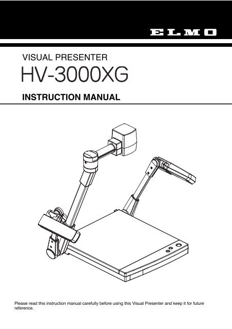
VISUAL PRESENTER INSTRUCTION MANUAL - ELMO USA Corp.
VISUAL PRESENTER INSTRUCTION MANUAL - ELMO USA Corp.
VISUAL PRESENTER INSTRUCTION MANUAL - ELMO USA Corp.

Create successful ePaper yourself
Turn your PDF publications into a flip-book with our unique Google optimized e-Paper software.
IMPORTANT SAFEGUARDSRead Instructions – All the safety and operatinginstructions should be read before the appliance isoperated.Retain Instructions – The safety and operatinginstructions should be retained for future reference.Heed Warnings – All warnings on the product andin the operating instructions should be adhered to.Follow Instructions – All operating and useinstructions should be followed.Cleaning – Unplug this product from the walloutlet before cleaning. Do not use liquid cleaners oraerosol cleaners. Use a damp cloth for cleaning.Attachments – Do not use attachments notrecommended by the product manufacturer as theymay cause hazards.Water and Moisture – Do not use this productnear water - for example, near a bath tub, wash bowl,kitchen sink, or laundry tub, in a wet basement, ornear a swimming pool, and the like.Accessories – Do not place this product on anunstable cart, stand, tripod, bracket, or table. Theproduct may fall, causing serious injury to a child oradult, and serious damage to the product. Use onlywith a cart, stand, tripod, bracket, or tablerecommended by the manufacturer, or sold with theproduct. Any mounting of the product should followthe manufacturer's instructions, and should use amounting accessory recommended by themanufacturer.Ventilation – Slots and openings in the cabinetare provided for ventilation and to ensure reliableoperation of the product and to protect it fromoverheating, and these openings must not be blockedor covered. The openings should never be blockedby placing the product on a bed, sofa, rug, or othersimilar surface. This product should not be placed ina built-in installation such as a bookcase or rackunless proper ventilation is provided or themanufacturer's instructions have been adhered to.Power Sources – This product should be operatedonly from the type of power source indicated on themarking label. If you are not sure of the type ofpower supply to your home consult your appliancedealer or local power company. For productsintended to operate from battery power, or othersources, refer to the operating instructions.Grounding or Polarization – This product may beequipped with either a polarized 2-wire AC line plug(a plug having one blade wider than the other) or a 3-wire grounding type plug, a plug having a third(grounding) pin. The 2-wire polarized plug will fit intothe power outlet only one way. This is a safetyfeature. If you are unable to insert the plug fully intothe outlet, try reversing the plug. If the plug still failsto fit, contact your electrician to replace yourobsolete outlet. Do not defeat the safety purpose ofthe polarized plug. The 3-wire grounding type plugwill fit into a grounding type power outlet. This is asafety feature. If you are unable to insert the pluginto the outlet, contact your electrician to replaceyour obsolete outlet. Do not defeat the safetypurpose of the grounding type plug.Power-Cord Protection – Power-supply cordsshould be routed so that they are not likely to bewalked on or pinched by items placed upon oragainst them, paying particular attention to cords atplugs, convenience receptacles, and the point wherethey exit from the product.Lightning – For added protection for this productduring a lightning storm, or when it is left unattendedand unused for long periods of time, unplug it fromthe wall outlet and disconnect the antenna or cablesystem. This will prevent damage to the product dueto lightning and power-line surges.Overloading – Do not overload wall outlets,extension cords, or integral convenience receptaclesas this can result in a risk of fire or electric shock.A product and cartcombination should be movedwith care. Quick stops,excessive force, and unevensurfaces may cause theproduct and cart combinationto overturn.Object and Liquid Entry – Never push objects ofany kind into this product through openings as theymay touch dangerous voltage points or short-outparts that could result in a fire or electric shock.Never spill liquid of any kind on the product.Servicing – Do not attempt to service this productyourself as opening or removing covers may exposeyou to dangerous voltage or other hazards. Refer allservicing to qualified service personnel.1
Damage Requiring Service – Unplug this productfrom the wall outlet and refer servicing to qualifiedservice personnel under the following conditions:When the power-supply cord or plug is damaged.If liquid has been spilled, or objects have fallen intothe product.If the product has been exposed to rain or water.If the product does not operate normally by followingthe operating instructions. Adjust only those controlsthat are covered by the operating instructions as animproper adjustment of other controls may result indamage and will often require extensive work by aqualified technician to restore the product to itsnormal operation.If the product has been dropped or damaged in anyway.When the product exhibits a distinct change inperformance - this indicates a need for service.Replacement Parts – When replacement parts arerequired, be sure the service technician has usedreplacement parts specified by the manufacturer orhave the same characteristics as the original part.Unauthorized substitutions may result in fire, electricshock or other hazards.Safety Check – Upon completion of any service orrepairs to this product, ask the service technician toperform safety checks to determine that the productis in proper operating condition.Heat – The product should be situated away fromheat sources such as radiators, heat registers,stoves, or other products (including amplifiers) thatproduce heat.SA 1965SA 1966CAUTION:CAUTIONRISK OF ELECTRIC SHOCKDO NOT OPENTO REDUCE THE RISK OF ELECTRICSHOCK, DO NOT REMOVE COVER(OR BACK). NO USER-SERVICEABLEPARTS INSIDE. REFER SERVICING TOQUALIFIED SERVICE PERSONNEL.The lightning flash with arrowhead symbol, withinan equilateral triangle, is intended to alert the userto the presence of uninsulated "dangerousvoltage" within the product's enclosure that maybe of sufficient magnitude to constitute a risk ofelectric shock to persons. This marking is locatedat the bottom of product.The exclamation point within an equilateraltriangle is intended to alert the user to thepresence of important operating and maintenance(servicing) instructions in the literatureaccompanying the product.WARNING:TO REDUCE THE RISK OF FIRE ORELECTRIC SHOCK, DO NOT EXPOSETHIS PRODUCT TO RAIN ORMOISTURE.THIS IS A CLASS A PRODUCT.IN A DOMESTIC ENVIRONMENT THISPRODUCT MAY CAUSE RADIOINTERFERENCE IN WHICH CASE THEUSER MAY BE REQUIRED TO TAKEADEQUATE MEASURES.INFORMATIONThis equipment has been tested and found tocomply with the limits for a Class A digital device,pursuant to Part 15 of the FCC Rules. These limitsare designed to provide reasonable protectionagainst harmful interference when the equipment isoperated in a commercial environment. Thisequipment generates, uses, and can radiate radiofrequency energy and, if not installed and used inaccordance with the instruction manual, may causeharmful interference to radio communications.Operation of this equipment in a residential area islikely to cause harmful interference in which casethe user will be required to correct the interferenceat his own expense.USER-INSTALLER CAUTION:Your authority to operate this FCC verifiedequipment could be voided if you make changes ormodifications not expressly approved by the partyresponsible for compliance to Part 15 of the FCCrules.2
BEFORE YOU USEUse the Visual Presenter under the rated electrical conditions.Do not leave the Presenter under direct sunlight or by heaters, or the Presenter may be discolored,deformed, or damaged.Do not place the Presenter in any humid, dusty, windy or vibrating location. Use the Presenter in thefollowing environmental conditions:Temperature : 5°C ~ 40°C (41°F ~ 104°F)Humidity : 30 ~ 85% (No condensation)Use a soft, dry cloth for cleaning. Do not use any volatile solvent, such as thinner or benzine.Do not directly point the camera lens into the sun, or the camera may be damaged.Caring for the batteries :• If the Presenter is not used for a long time, take out the batteries from the remote control.• Do not use rechargeable Ni-Cd batteries.• Do not use new and old batteries, or batteries of different types together.• Do not try to recharge or short-circuit the batteries.3
CONTENTS1. PART NAMES AND FUNCTIONS . . . . . . . . . . . . . . . . . . . . . . . . . . . . . . . . . . . . . . . . 6Appearance . . . . . . . . . . . . . . . . . . . . . . . . . . . . . . . . . . . . . . . . . . . . . . . . . . . . . . . . . . . . . . . . . . . . . . . . 6Front Operation Panel . . . . . . . . . . . . . . . . . . . . . . . . . . . . . . . . . . . . . . . . . . . . . . . . . . . . . . . . . . . . . . . . 7Rear Panel . . . . . . . . . . . . . . . . . . . . . . . . . . . . . . . . . . . . . . . . . . . . . . . . . . . . . . . . . . . . . . . . . . . . . . . . 7Wireless Remote Control and Column . . . . . . . . . . . . . . . . . . . . . . . . . . . . . . . . . . . . . . . . . . . . . . . . . . . 92. WIRELESS REMOTE CONTROL . . . . . . . . . . . . . . . . . . . . . . . . . . . . . . . . . . . . . . . . 10Preparation . . . . . . . . . . . . . . . . . . . . . . . . . . . . . . . . . . . . . . . . . . . . . . . . . . . . . . . . . . . . . . . . . . . . . . . 103. MOUSE . . . . . . . . . . . . . . . . . . . . . . . . . . . . . . . . . . . . . . . . . . . . . . . . . . . . . . . . . . . . 104. SETTING UP . . . . . . . . . . . . . . . . . . . . . . . . . . . . . . . . . . . . . . . . . . . . . . . . . . . . . . . . 11Preparation of the Visual Presenter . . . . . . . . . . . . . . . . . . . . . . . . . . . . . . . . . . . . . . . . . . . . . . . . . . . . 11Connection to the monitor and the projector . . . . . . . . . . . . . . . . . . . . . . . . . . . . . . . . . . . . . . . . . . . . . . 12RGB input signal . . . . . . . . . . . . . . . . . . . . . . . . . . . . . . . . . . . . . . . . . . . . . . . . . . . . . . . . . . . . . . . . . . . 14RGB output signal . . . . . . . . . . . . . . . . . . . . . . . . . . . . . . . . . . . . . . . . . . . . . . . . . . . . . . . . . . . . . . . . . . 145. OPERATION PROCEDURES . . . . . . . . . . . . . . . . . . . . . . . . . . . . . . . . . . . . . . . . . . . 15Simple steps for presenting printed material . . . . . . . . . . . . . . . . . . . . . . . . . . . . . . . . . . . . . . . . . . . . . . 15Convenient use of the camera . . . . . . . . . . . . . . . . . . . . . . . . . . . . . . . . . . . . . . . . . . . . . . . . . . . . . . . . 156. STORING THE <strong>VISUAL</strong> <strong>PRESENTER</strong> . . . . . . . . . . . . . . . . . . . . . . . . . . . . . . . . . . . . 167. VARIOUS FUNCTIONS . . . . . . . . . . . . . . . . . . . . . . . . . . . . . . . . . . . . . . . . . . . . . . . . 17Lighting . . . . . . . . . . . . . . . . . . . . . . . . . . . . . . . . . . . . . . . . . . . . . . . . . . . . . . . . . . . . . . . . . . . . . . . . . . 17Zoom . . . . . . . . . . . . . . . . . . . . . . . . . . . . . . . . . . . . . . . . . . . . . . . . . . . . . . . . . . . . . . . . . . . . . . . . . . . . 17Video pointer . . . . . . . . . . . . . . . . . . . . . . . . . . . . . . . . . . . . . . . . . . . . . . . . . . . . . . . . . . . . . . . . . . . . . . 18Focus . . . . . . . . . . . . . . . . . . . . . . . . . . . . . . . . . . . . . . . . . . . . . . . . . . . . . . . . . . . . . . . . . . . . . . . . . . . 18Iris . . . . . . . . . . . . . . . . . . . . . . . . . . . . . . . . . . . . . . . . . . . . . . . . . . . . . . . . . . . . . . . . . . . . . . . . . . . . . . 19Pause . . . . . . . . . . . . . . . . . . . . . . . . . . . . . . . . . . . . . . . . . . . . . . . . . . . . . . . . . . . . . . . . . . . . . . . . . . . 20Auto white balance . . . . . . . . . . . . . . . . . . . . . . . . . . . . . . . . . . . . . . . . . . . . . . . . . . . . . . . . . . . . . . . . . 20About the PC software "Image Mate for HV-400XG/3000XG/3500XG" . . . . . . . . . . . . . . . . . . . . . . . . . 204
8. OSD (On-Screen Display) . . . . . . . . . . . . . . . . . . . . . . . . . . . . . . . . . . . . . . . . . . . . . 21Display of the OSD menu and the operation of the mouse . . . . . . . . . . . . . . . . . . . . . . . . . . . . . . . . . . . 21OSD menu . . . . . . . . . . . . . . . . . . . . . . . . . . . . . . . . . . . . . . . . . . . . . . . . . . . . . . . . . . . . . . . . . . . . . . . 229. COMMUNICATION THROUGH RS-232C . . . . . . . . . . . . . . . . . . . . . . . . . . . . . . . . . . 24Setting up . . . . . . . . . . . . . . . . . . . . . . . . . . . . . . . . . . . . . . . . . . . . . . . . . . . . . . . . . . . . . . . . . . . . . . . . 24Cable connection . . . . . . . . . . . . . . . . . . . . . . . . . . . . . . . . . . . . . . . . . . . . . . . . . . . . . . . . . . . . . . . . . . 25RS-232C connector specifications (DSUB-9P) . . . . . . . . . . . . . . . . . . . . . . . . . . . . . . . . . . . . . . . . . . . . 25Data format specifications . . . . . . . . . . . . . . . . . . . . . . . . . . . . . . . . . . . . . . . . . . . . . . . . . . . . . . . . . . . . 26Transmission specifications . . . . . . . . . . . . . . . . . . . . . . . . . . . . . . . . . . . . . . . . . . . . . . . . . . . . . . . . . . 26Table of the communication commands . . . . . . . . . . . . . . . . . . . . . . . . . . . . . . . . . . . . . . . . . . . . . . . . . 2710. TROUBLESHOOTING HINTS . . . . . . . . . . . . . . . . . . . . . . . . . . . . . . . . . . . . . . . . . 2911. SPECIFICATIONS . . . . . . . . . . . . . . . . . . . . . . . . . . . . . . . . . . . . . . . . . . . . . . . . . . . 30GeneralCameraLightingSupplied accessories5
1. PART NAMES AND FUNCTIONSAppearance9. Infrared Sensor10. Camera Head Arm3. Camera Head5. Lighting Unit2. Column4. Close-up Lens Holder(Attach this holder for normaluse. Swing away this holder forviewing a far-away object.)6. Lighting Arm (L)5. Lighting Unit1. Stage6. Lighting Arm (R)8. Remote Control StorageCompartment7. Front Operation Panel6
Front Operation Panel11. Zoom Buttons12. Auto Focus ButtonName Function Reference Page11 Zoom Buttons To change the image size.12 Auto Focus Button To focus automatically (One-shot auto focus).P.17, P.18P.15, P.18Rear Panel15. RS-232C Terminal[RS-232C]19. Video-out Terminal[VIDEO OUT]13. Power cord Receptacle[AC IN]17. RGB-in Terminal[RGB IN]AC INONPOWERRS-232CRGB OUTRGB INVIDEOOUTUSBOFF01A B C D14. Power Switch[POWER]18. USB Terminal[USB]16. RGB-out Terminal[RGB OUT]20. In/Out Selector SwitchName Function Reference Page13 Power Cord Receptacle [AC IN] To connect the power cord.14 Power Switch [POWER] To turn ON/OFF the power supply. P.1515 RS-232C Terminal To connect an RS-232C cable for communication with P.24[RS-232C]a PC.The [D] key of the In/Out selector switch enables eitherone of the following:• To control the Visual Presenter from the outsidethrough the RS-232C.• To use the supplied mouse.7
Name Function Reference Page16. RGB-out Terminal To output the image when connected to RGB input P.12, P.14[RGB OUT]equipment, such as LCD projector and multi-syncmonitor.17. RGB-in Terminal To output the image from RGB-out Terminal P.14[RGB IN][RGB OUT] when RGB1 is selected for input.18. USB Terminal [USB] To connect a USB cable. P.20When the supplied USB cable is connected here, theimage can be captured or the Presenter can be controlledon the supplied CD-ROM "Image Mate for HV-400XG/3000XG/3500XG."19. Video-out Terminal To connect to a monitor or other output equipment. P.12[VIDEO OUT]20. In/Out Selector Switch To select In/Out as follows: P.10, P12[A] keyTo select the image output from RGB-out terminal[RGB OUT].XGA outputTV outputNote: When "TV output" is selected, only thepresenter image can be seen on TVmonitor. (not picture from [RGB IN].)[B] keyTo select the TV output system.NTSCPAL[C] keyTo select the shutter frequency.In the area where the power frequency for the shutteris 50Hz, the screen may flicker due to AC dischargelamp, such as fluorescent lamp and mercury lamp.This flicker may be reduced by setting the switch to50Hz.60Hz50Hz[D] keyTo select the RS-232C.Use of the mouseControl of the Presenter01Key arrangement and their functionsA B C DXGA NTSC 60Hz MouseTV PAL 50Hz Control8
Wireless Remote Control21. POINTER22. DirectionsS-VIDEOOUTPUT23. PAUSE26. MAIN28. TELE29. WIDE32. AUTO IRIS33. OPEN 34. CLOSE24. AUTO WHITEBALANCE25. LAMP27. RGB131. FAR30. NEAR35. AF36. S-video Output Terminal[S-VIDEO OUTPUT]Button Name Function Reference Page21 POINTER To display the video pointer on the screen.P.1822 Directions To move the video pointer while it is displayed.P.1823 PAUSE To make the image pause still.P.2024 AWB To obtain the white balance automatically.P.2025 LAMP To turn ON/OFF the upper lighting units.P.1726 MAIN To switch the image output of the RGB-out terminal[RGB OUT] to the Presenter camera image.27 RGB1 To switch the image output of the RGB-out terminal[RGB OUT] to RGB-in Terminal [RGB IN].Note: When [1] (TV) is chosen by [A] key of theIn/Out selector switch in the rear, the videoimage on TV cannot be changed.28 TELE To zoom in.P.15, P.17, P.1829 WIDE To zoom out.P.15, P.1730 NEAR To move the focus near.P.1931 FAR To move the focus far.P.1932 AUTO IRIS To set the initial setting.P.1933 OPEN To open the iris.P.1934 CLOSE To close the iris.P.1935 AF To focus automatically.P.15, P.1836 S-video output Terminal To connect to a monitor or other epuipment.P.13[S-VIDEO OUTPUT]9
2. WIRELESS REMOTE CONTROLPoint the infrared emitting part of the wireless remote control unit at the infrared sensor of the Visual Presenter, locatedon the top of the column, and press the button for the desired function.The receivable range may be narrowed when the Presenter is placed under sunlight, near an inverter fluorescent lampor in any other unfavorable surroundings. Depending on the conditions of fluorescent lamps, etc. the sensor may fail toreceive the infrared light. In such a case, relocate the Presenter, or take other countermeasures.Receivable rangeDistance : Approx. 7 m (23 ft.) or less from the light receiving area to the front of the wireless remote controlAngle : Approx. 30 degrees or less from the light receiving area to the front of the wireless remote controlrightward, leftward, upward and downward, respectively30˚30˚30˚30˚30˚30˚30 ˚30˚PreparationRemove the battery case cover by pressing downward on the [ ] mark part in the direction as indicated by the arrow.Install 2 pcs of batteries (type R03, AAA) into the case in the direction as indicated there.Note: Install the batteries with the right polarity.Note: Change the batteries once a year.Note: The batteries supplied with the Presenter are only for use in initially confirming the operation of the Presenter.It is not guaranteed that these batteries can work effectively for the indicated period.3. MOUSESelect [0] by using the [D] key of the In/Out selector switch, and connect the mouse to the RS-232C terminal on therear panel. Then, "OSD" and "video pointer" can be displayed and operated.Reference • Video pointer P.18• Display of the OSD menu andthe operation of the mouse P. 2110
4. SETTING UPPreparation of the Visual Presenter(1) Raise the column.Raise up the column once, and fall it until it islocked.Note: The lighting arm (L) cannot beindependently raised.Note: Unless the column is fully raised up, it maynot be locked when it is fallen.(2) Raise the lighting arm (R) unit, and turn the camerahead to direct the lens unit to the stage.(3) Turn the lighting unit.(4) Open the lighting arm unit and the lighting unit.(5) Plug the power cord into the power cord receptacleof the Presenter and the outlet.11
Connection to the monitor and the projectorThe Visual Presenter can switch the type of image output by using the In/Out selector switch. Use the In/Out selectorswitch according to the connection environment. It is set before shipment as follows:KeyABCDFunctionTo switch the image output.To switch the TV output system.To switch the shutter frequency.To switch the RS-232C.Initial settingKey selection Contents0 XGA output0 NTSC0 60Hz0 Use of the mouseNote: Be sure to turn OFF the power of all peripheral equipment before making any connections to protect thePresenter and all the connected equipment.Note: Be sure to turn OFF the power of the Presenter before switching the key of the In/Out selector switch.Note: Hold the cable plug part when connecting or disconnecting the cables.Connection to the composite video-in terminalConnect the video-out terminal [VIDEO OUT] of the Presenter and the video in terminal of other equipment withthe supplied RCA video cable connection.AC INONPOWERRS-232CRGB OUTRGB INVIDEOOUTUSBMonitor TVOFF01A B C DNote: The image output from the video-out terminal [VIDEO OUT] is only the Presenter camera image.Connection to the RGB video-out terminalConnect the RGB-out terminal [RGB OUT] of the Presenter and the RGB video-in terminal of equipment with thesupplied analog RGB cable or a connection cable available in the market.At this point, the image position may be shifted from the center. In such a case, adjust manually the horizontal andvertical positions from the connected equipment side.For LCD projector, vertical stripes may appear on the screen. This can be reduced by manually adjusting the dotclock frequency on the projector side.Note: When the connected equipment requires 5 connections of R, G, B, H and V, select [XGA] in the [A] key of theIn/Out selector switch.When the connected equipment requires only 3 connections of R, G and B, select [TV] in the [A] key of theIn/Out selector switch.LCD projectorAC INONOFFPOWERRS-232CRGB OUTRGB INVIDEOOUTUSB01A B C DMonitor12
Connection to the S-Video terminalConnect the S-video ouput terminal [S-VIDEO OUTPUT] of the Column of the Presenter and the video-in terminalof other equipment with the supplied S-video cable.Monitor TVS-VIDEOOUTPUTNote: The image output from the S-video output terminal [S-VIDEO OUTPUT] is only the Presenter camera image.13
RGB input signalSignal assignmentPin No.12345NameVideo signal (Red)Video signal (Green)Video signal (Blue)NCGNDPin No.678910NameGND (Red)GND (Green)GND (Blue)NCGNDPin No.Name11GND12NC13 Horizontal synchronizing/Composite synchronizing signal14 Vertical synchronizing signal15NCPin arrangement54 3 2 110 9 8 7 615 14 13 12 11DSUB 15P shrinking terminal(Female)Input signalVideo signalHorizontal synchronizing signalVertical synchronizing signalComposite synchronizing signalAnalog 0.7V(p-p) 75ΩTTL level (positive / negative polarity)TTL level (positive / negative polarity)TTL level (positive / negative polarity)RGB output signalSignal assignmentPin No.12345NameVideo signal (Red)Video signal (Green)Video signal (Blue)NCGNDPin No.678910NameGND (Red)GND (Green)GND (Blue)NCGNDPin No.1112131415NameGNDNCHorizontal synchronizing signalVertical synchronizing signalNCTerminal arrangement and analog RGB cable connectionDSUB 15P shrinkingterminal (Male)12 3 4 56 7 8 9 1011 12 13 14 15Presenter side(DSUB 15P)Video signal (Red)Video signal (Green)Video signal (Blue)1234GND 5GND (Red)GND (Green)GND (Blue)GNDGNDHorizontal synchronizing signalVertical synchronizing signal678910111213141514RGB input terminalunit side(BNC)RedGreenBlueGrayBlackR signalG signalB signalHorizontal synchronizing signalVertical synchronizing signal
5. OPERATION PROCEDURESSimple steps for presenting printed material(1) Turn ON the power switch.Note: Before turning ON the power switch,connection to the monitor should have beencompleted.ONPOWERRS-232Note: If the power switch is turned ON immediatelyafter being turned OFF, the Visual Presentermay not operate. For restarting, turn ON thepower switch several seconds after turningOFF.AC INOFFPOWERRS-232CONOFFRGB OUTRGB INVIDEOOUTUSB01A B C D(2) Place the object on the stage. Adjust the image sizeaccording to the object size using the zoom buttons[TELE/WIDE] on the operation panel or wirelessremote control, watching the image on the monitor.Front operation panelRemote control(3) Press the button [AUTO FOCUS] on the frontoperation panel or the auto focus button [AF] onremote control for focusing.Note: The auto focus function works up to a height ofapprox. 15 cm (5.9 in.) above the stagesurface on the maximum side of the zoom[TELE] (when a close-up lens is attached).Front operation panelRemote controlConvenient use of the cameraWhen the camera head arm is turned as shown in theright figure, material outside the stage can bephotographed. When the camera head unit is set in thehorizontal position, wall view, distant view, etc. can bephotographed.When the object is far away, open the close-up lensholder to your side.ReferenceThe focus can be achieved from 0.5 m(20 in.) to .Close-up lensholder15
6. STORING THE <strong>VISUAL</strong> <strong>PRESENTER</strong>(1) Turn OFF the power switch, and unplug the powercord and the video cable.(2) Close the lighting unit and the lighting arm unit.(3) Turn the lighting unit to the position shown in the rightfigure.Note: Be sure to return the lighting unit to its originalposition as shown in the right figure. If it is inany other position when it is put away, thelighting unit may be damaged.(4) Fall the lighting arm (R) unit, and turn the camera headto the position shown in the right figure (the positionwith the camera head slightly turned to the rear sidepanel).Note: The lighting arm (L) cannot be independentlyfallen.Note: Be sure to return the camera to its originalposition as shown in the right figure. If it is inany other position when it is put away, thecamera head or the lens may be damaged.(5) Raise up the column once, and then fall it.Note: The right storage position of the column isshown in the right figure. Never applyexcessive force to the column.Note: Do not hold the head arm unit when carryingthe Presenter.16
7. VARIOUS FUNCTIONSLightingThe lighting for presenting printed matter or othermaterial is standard equipment.Each time the lighting button [LAMP] on the wirelessremote control is pressed, the lighting operates in orderof the L-side lamp alone lights up the L- and R-side lamps go off the L- and R-side lamps lightup.Remote controlReference OSD menu P.22ReferenceWhen the R-side lamp unit is put awaywhile the L-side lamp alone is lighting,large material can be effectively moved.Note: When the lightness of the material surface is notsufficiently high or a 3-D object is presented, asharp image with good color rendering can beobtained with the lighting unit on.ZoomThe 10-time optical zoom is enabled.Press the button [TELE] on the front operation panel orthe zoom button [TELE] on the wireless remotecontrol, and the image will be gradually be enlarged.Front operation panelRemote controlPress the button [WIDE] on the front operation panel orthe zoom button [WIDE] on the wireless remotecontrol, and the image will be gradually reduced.Front operation panelReference OSD menu P.22Remote control17
Video pointerRemote controlWhen the pointer button [POINTER] on the wirelessremote control is pressed or the left button of themouse is clicked, the video pointer appears.The video pointer is moved by using the directionbuttons on the wireless remote control or by movingthe mouse.When the pointer button [POINTER] on the wirelessremote control is pressed or the left button of themouse is clicked (this switches the OSD display), thevideo pointer disappears.Appear/ScrollMouseReference• Display of the OSD menu and theoperation of the mouse P.21• OSD menu P.22Note: This function effects only for the image fromthe RGB-out terminal [RGB OUT].FocusAuto FocusPress the button [AUTO FOCUS] on the frontoperation panel or the auto focus button [AF] on thewireless remote control, and the auto focus operationwill be activated.While the auto focus is in operation, the indicationlamp blinks until the object is brought into focus.Front operation panelRemote controlThe Presenter features one-shot auto focus function.Once focusing is completed, the auto focus function isreleased, and the focused position maintainsunchanged. (FOCUSFREE)Enlarge the image to the maximum size by pressing thebutton [TELE] on the front operation panel or the zoombutton [TELE] on the wireless remote control andactivate the auto focus operation, and the image willbecome sharper.Front operation panelRemote controlReference OSD menu P.2218
However, the objects listed below may not be broughtinto focus in the auto focus mode. In these cases, use themanual focus mode.· Objects bearing little contrast· Objects with fine repeated patterns, such as lateralstripes and cross stripes· Objects glittering or reflecting strong light· Objects with bright background, or excessive contrast· Objects in a dark picture plane· Objects located near and far away at the same time.· Objects in motionIf the focus button [NEAR] or [FAR] on the wirelessremote control is pressed while the auto focus is inoperation, the auto focus will be released.Remote controlNote: The auto focus functions up to approx. 15 cm(5.9 in.) above the stage surface (with theclose-up lens attached).Powered Manual FocusTo focus on any part of the material, such as 3-Dmaterial, press the focus button [NEAR] or [FAR] onthe wireless remote control.Remote controlReference OSD menu P.22Note: The auto focus function works up to a height ofapprox. 15 cm (5.9 in.) above the stagesurface on the maximum side of the zoom[TELE] (when a close-up lens is attached).IrisThe iris level can be adjusted.To open the iris, press the open button [OPEN] on thewireless remote control.To close the iris, press the close button [CLOSE] on thewireless remote control.To reset the setting to the initial setting, press the auto irisbutton [AUTO IRIS] on the wireless remote control.Remote controlReference OSD menu P.22Note: If the screen looks dark, press the iris button[OPEN] on the wireless remote control to adjustthe brightness of the screen.19
PauseWhen the pause button [PAUSE] on the wirelessremote control is pressed, the image of the main camerais stored in pause still mode.When the pause button [PAUSE] is pressed again, thepause mode is released.Remote controlReference OSD menu P.22Note: Pressing the other buttons for each function(except Directions and [POINTER]) alsocancels the pause mode.Note: The pause (still) mode is inactive for the videoimage from [VIDEO OUT].Auto white balanceWhen the auto white balance button [AWB] on thewireless remote control is pressed, the white balancewill be automatically adjusted according to the colortemperature.Remote controlReference OSD menu P.23About the PC software "Image Mate for HV-400XG/3000XG/3500XG"When the application [Image Mate for HV-400XG/3000XG/3500XG] is installed, the following operation are enabled:• Image data transfer to the PC• Operation of the Visual Presenter by the PCFor further detail, refer to the installation manual for the application [Image Mate for HV-400XG/3000XG/3500XG]and the file [manual.pdf] in the CD-ROM.20
8. OSD (On-Screen Display)OSD (On-Screen Display) means the operation menu displayed on the screen ("OSD menu"). The operation of VisualPresenter with the mouse can be set from this OSD menu.Note: The OSD function effects only for the image from the RGB-out terminal [RGB OUT].Display of the OSD menu and the operation of the mouseWhen the left button of the mouse is clicked, the OSD menu and the pointer appear.Each function item is set by using the mouse.MouseUse the following buttons on the mouse for each function:• Left button-----------Each time the mouse is clicked, the pointer and the menu alternately appear anddisappear.PointerappearanceMenuMenuclick click clickappearancedisappearancePointerdisappearanceclick• Right button---------Not used.For the information how to operate the pointer, refer to P.18.Note: The OSD is supposed to be used in a large projection size with a projector or the like.If the OSD is used on monitor or a TV, the display may not be clearly seen.21
OSD menuThe main menu items can be set also from the front operation panel of the main body or the remote control.IconNameLighting unitON/OFFColor/B&W selectionPauseAuto focusFunctionTo turn ON/OFF the upper lighting unit. When the OSD menu isdisplayed for the first time, the previous setting is maintained. Each timethis icon is clicked with the left button of the mouse, the lighting unit isswitched in order of two lamps one lamp (left) OFF.To switch the color/B&W setting. When the OSD menu is displayed forthe first time, the screen is in the color setting. When this icon is clickedwith the left button of the mouse, the icon changes and the color setting isswitched to the B&W setting.To switch the Still/Live setting. When the OSD menu is displayed for thefirst time, the screen is in the moving setting. When this icon is clickedwith the left button of the mouse, the icon changes and the Live setting isswitched to the still setting.Note: Clicking the other icons for each function (except Pointer)also cancels the pause mode.The object is automatically brought in focus. When this icon is clickedwith the left button of the mouse, the auto focus is activated.ZoomTELE/WIDEThe image size is adjusted. When this icon is held down with the mouse,the zoom lens is activated.FocusNEAR/FARThe focus is adjusted. When this icon is held down with the mouse, thefocus is activated.IrisOPEN/CLOSETo adjust the auto iris level. When this icon is held down with the mouse,the lens iris is activated.PointerTo change the color and shape of the pointer on the screen. Each time thisicon is clicked with the left button of the mouse, the pointer color changesin order of white red green blue.22
IconNameWhite balanceFunctionOne-push white balance or manual white balance can be selected.One pushTo set the one-push white balance. When the left button of the mouse isclicked, the white balance of the color temperature is fixed.ManualTo set the white balance by turning the knob//.Click the direction buttons to adjust the white balance with the left button ofthe mouse. ...........To adjust the red component. (-31 ~ +31) ...........To adjust the green component. (-31 ~ +31) ...........To adjust the blue component. (-31 ~ +31)Aperture selectionON/OFFThe image enhancer (contour) is switched. When the OSD menu isdisplayed for the first time, the image enhancer setting is maintained.The aparture has been set to ON before factory-shipment.Gamma selectionON/OFFThe gamma selection (0.6/1.0) is switched. When the OSD menu isdisplayed for the first time, the gamma selection setting is maintained.The gamma has been set to OFF (1.0) before factory-shipment.Status savingThe present status and adjusted values are saved. The status of lighting unitON/OFF, aperture, gamma and the gain values of , and of manual white balance, auto iris level are saved.InitializationThe adjusted values are reset to the values set before factory-shipment.23
9. COMMUNICATION THROUGH RS-232CThe Visual Presenter can be controlled by a connected PC through the RS-232C terminal [RS-232C].Setting up(1) Connect the Presenter to a PC with an RS-232C connection cable.Here, set the [D] key of the In/Out selector switch to [1].Note: When using an RS-232C cable available in the market, make sure of the connection shown below.Note: To protect the Presenter and the PC, be sure to turn OFF all the power switches of all equipment beforeconnecting.(2) Start the PC, and set the communication mode of the RS-232C to the communication mode of the Presenter.Note: For the information how to set the communication mode of the RS-232C, refer to the instruction manual of thePC.(3) Start the PC program to operate the Presenter.(4) Control through the RS-232C will start.Note: For communication control, be sure to take the above steps for setting.Note: If the RS-232C cable is not correctly connected between the Presenter and the PC, no response is transmitted.Connect the RS-232C cable correctly, and fix it firmly with the connector set screws before the operation.Cable connectionPresenter sideDSUB-9PPC/AT sideDSUB-9PDSUB-9P (Female)5 4 3 2 19 8 7 6CDRXDTXDDTRSGDSRRTSCTSRI (CI)123456789123456789CDRXDTXDDTRSGDSRRTSCTSRIDSUB-9P (Female)5 4 3 2 19 8 7 624
RS-232C connector specifications (DSUB-9P)Pin No.CodeNameDirection of dataPresenter PC1CDCarrier Detect2RXDReceived Data3TXDTransmitted Data4DTRData Terminal Ready5SGSignal Ground6DSRData Set Ready7RTSRequest To Send8CTSClear To SendData format specificationsThis command is executed in the form of 1-command/1 packet. The next command is not accepted until the previousprocessing is completed.• The communication command always starts with STX (Start of Text) [02H], and ends with ETX (End of Text) [03H].• If the communication format or command name is wrong, NAK (Negative Acknowledgement) [15H] will be sentfrom the Presenter as a result of failing to receive correctly.• When the communication format is correctly received, the Presenter sends ACK (Normal Acknowledgement) [06H].Transmission Command (PC Presenter)Each operation command is executed in ASCII code, and transmitted in a set of 7 bytes as follows:(PC)STXCommandParameterDataETX[02H] [03H](Presenter) ACK[06H]All response data are sent in ASCII code in correspondence to the parameters on the table of the communication commands.• Status request format (Parameter 0)(Presenter)STXLighting Inputselection selection30HColor/B&WPointerdisplay30HPauseLocalLock outETX• Status request format (Parameter 2)(Presenter)STX30HGammaselection30HApartureselection30H30H30H30HETX• ROM version(Presenter)STXV56HH48HE45HHHHETXVersion25
Transmission specifications• Full duplex start-stop sync. mode• Start bit• Data bit• Stop bit• Parity bit• X parameter• Baud rate (Communication speed): 1 bit: 8 bits: 1 bit: None: None: 9600bpsTable of the communication commandsFunction Command Parameter Data CommentsAuto Focus AF 0Command to execute the one-shot auto focus.Auto WhiteBalanceAW0Command to execute the one-push auto white balance.FocusadjustmentFO+ (NEAR)– (FAR)0 (STOP)Command to adjust the focus.ZoomadjustmentZO+ (TELE)– (WIDE)0 (STOP)Command to adjust the Zoom.Iris adjustmentIR+ (OPEN)– (CLOSE)0 (STOP)1 (NORMAL)Command to adjust the Iris.LightingselectionPL0 (OFF)1 (1 lamp)2 (2 lamps)Command to select the Lighting.Color/B&WselectionCB0 (COLOR)1 (B&W)Command to select Color/B&W.Input selectionAV0 (MAIN)1 (RGB1)Command to select the Input.Pointer displayPO0 (OFF)1 (ON)Command to turn ON/OFF the Pointer display.PointermovementPMCommand to move the video pointer.1: To the right side2: To the left side3: To the upper side4: To the lower side5: To the upper right6: To the upper left7: To the lower right8: To the lower left26
Function Command Parameter Data CommentsPauseFZ0 (OFF)1 (ON)Command to pause the image.Local lockoutLL0 (OFF)1 (ON)Command to invalidate the switches on the front operationpanel and wireless remote control.GammaselectionGM0 (1.0)1 (0.6)Command to switch the gamma setting value of the image.ApartureselectionAP0 (OFF)1 (ON)Command to switch the sharpness (edge effect) of the image.DefaultDF0Command to reset to the initialized mode.Status requestQS02Command to inquire the status of the equipment.ROM versionQR0Command to refer to the ROM version.AcknowledgecheckSA0 (OFF)1 (ON)Command to select the command acknowledge for eachoperation command. (Default :ON)Add CRcommandSC0 (OFF)1 (ON)Command to add CR [0Dh] to the end of the acknowledgedata. (Default :OFF)Note: "" in the data column means that SPACE [20H] should be transmitted twice.27
10. TROUBLESHOOTING HINTSSymptomNo image on the screenOut of focusThe lamp is not quickly turned ON.Image is too dark.The image of printed matter is striped.The image flickersPossible cause/countermeasure• Cable is not properly connected to the video-in terminal ofmonitor.• The power cord is disconnected from the wall AC outlet.• The plug is disconnected from the power cord receptacle of thePresenter.• The power switch is not turned ON.• Zoom is set at TELE to display only white/black part of thematerial.• The switch is turned ON immediately after it is turned OFF. Inthis case, the Presenter may not start. Wait several seconds afterturning OFF the power switch, and then turn ON the powerswitch.• The In/Out selector switch is not correctly selected according toconnected equipment (See P. 8 and 13).• The object is too close to the lens. Check if it does not standhigher than 15 cm (5.9 in.) above the stage surface.• Zoom is set at TELE after focusing at WIDE angle.Focus on the point of max. TELE.• In the auto focus, focusing is difficult in some cases.• For protection purposes, the lamp is turned ON after preheatingfor 2 seconds. This is not a fault.• The ambient light is not sufficient. Press the lighting unit button[LAMP] to turn ON the upper lamp.• This is caused by the interference between the dots of printedmatter and the scanning line.• The light from the discharge tube (50Hz) does not come to thescreen. This may be reduced by setting the [C] key of the In/Outselector switch to [1] (50Hz) (See P. 8).If the trouble still remains after checking the above, consult your dealer or an authorized <strong>ELMO</strong> service center.28
11. SPECIFICATIONSGeneralItemPower sourceRated currentOutside dimensionsAC120V0.5A60HzSpecifications500mm(W) X 612mm(D) X 99mm(H) (19.8 X 24.1 X 3.9 in.) - When folded706mm(W) X 403mm(D) X 575mm(H) (27.8 X 15.9 X 22.6 in.) - When set upWeight6.5 kgs (14.3 lbs) (main body only)Output terminal Composite-video output RCA pin jack/75Ω unbalancedInput terminalExt. control terminalRGB outS-video outputRGB inRS-232CUSBMini DSUB 15P connector (female)Mini DIN 4P connector/75Ω unbalancedMini DSUB 15P connector (female)DSUB 9P connector (male)Type B receptacle111111CameraItemLens f=5.8-58mm (10-time zoom) F2.8ZoomShooting areaLimit of focus adjustmentSpecificationsOptical 10-time powerd zoom with 2x speed340mm x 252mm (13.4 X 9.9 in.) max., 37mm x 28mm (1.5 X 1.1 in.) min.At the range of stage surface~150mm (5.9 in.) from the stage surface.0.5m (20 in.)~∞ (with the camera facing sideways and with no close-up lens).FocusingIrisImage pick-up elementEffective picture elementTotal picture elementsImage signal processingSync. systemRGB output resolutionS/N ratioOutput signalAuto / ManualAuto (with level adjustment) / Manual1/3" CCD1024 (H) x 768 (V)1077 (H) x 788 (V) (approx. 850,000 pixels)Digital signal processing (DSP)InternalMore than 600 TV lines (Horizontal) More than 600 TV lines (Vertical)48 dBRGB outputInterlace RGBoutputCompositevideooutputSignal frequencyXGA Horizontal frequency 48.363kHzVertical frequency 60.004Hz(1024 x 768 @60Hz) VESA conformableNTSCHorizontal frequency 15.734kHz Vertical frequency 59.940HzPALHorizontal frequency 15.625kHz Vertical frequency 50.000HzNTSC/PAL ConformableS-video outputNTSC/PAL ConformableWhite balanceElectronic shutter speedselectionColor/B&W selectionAuto / One-push / ManualProvidedProvided29
LightingLightingItemSpecificationsHigh frequency lighting mode (Model:FPL9EX-N)Supplied accessoriesNamePower cordRCA video cableAnalog RGB cable (BNC connector)VGA cable (Mini DSUB 15P connector)MouseCD-ROM "Image Mate for HV-400XG/3000XG/3500XG" (PC link software)USB cableInstallation manual for CD-ROM "Image Mate for HV-400XG/3000XG/3500XG"Infrared wireless remote controller (RCW-432)Batteries (Type R03, AAA)Instruction manualWarranty cardS-video cable (Mini DIN 4P connector)Quantity1111111112111Note:The specifications are subject to change without notice.Dimensions and weight are approximate.Trademark AcknowledgementsXGA is a registered trademark of International Business Machines.VESA is a registered trademark of Video Electronics Standards Association., <strong>ELMO</strong> are registered trademarks of <strong>ELMO</strong> CO.,Ltd.30
WARNING:Unauthorized recording of copyrighted slide films, materials,photographs, etc. may infringe on the rights of copyright ownersand be contrary to copyright laws.U.S.A.<strong>ELMO</strong> CO., LTD.6-14, Meizen-cho, Mizuho-ku,Nagoya, 467-8567, JapanOVERSEAS SUBSIDIARY COMPANIES<strong>ELMO</strong> Mfg. <strong>Corp</strong>.1478 Old Country Road, Plainview, NY 11803-5034Tel:(516)501-1400 Fax:(516)501-0429E-mail:elmo@elmousa.comweb:http://www.elmousa.com/Canada<strong>ELMO</strong> Canada Mfg. <strong>Corp</strong>.44 West Drive, Brampton, Ontario L6T 3T6Tel:(905)453-7880 Fax:(905)453-2391E-mail : info@elmocanada.comweb:http://www.elmocanada.com/Germany<strong>ELMO</strong> (Europe) G.m.b.HNeanderstr. 18, 40233 DüsseldorfTel : (0211)376051 Fax : (0211)376630E-mail : elmoeurope@AOL.comweb : http://www.elmo.de/Printed in Japan6X1VHEN02