MDR524 - DSL electronic ® GmbH
MDR524 - DSL electronic ® GmbH
MDR524 - DSL electronic ® GmbH

You also want an ePaper? Increase the reach of your titles
YUMPU automatically turns print PDFs into web optimized ePapers that Google loves.
Product Description<br />
Discontinued Product<br />
Tel.: 49 2162 40025<br />
Fax: 49 2162 40035<br />
info@dsl-<strong>electronic</strong>.de<br />
www.dsl-<strong>electronic</strong>.de<br />
<strong>DSL</strong><br />
<strong>electronic</strong> <strong>®</strong><br />
<strong>GmbH</strong><br />
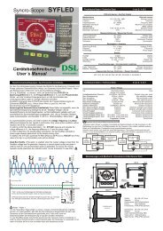
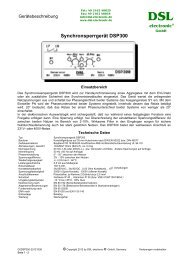
Electronic Speed Control Unit for Servomotors <strong>MDR524</strong><br />
Analog PI- Set-point Adjuster with Pulse Output for Supply of DC- Servomotors<br />
Application<br />
The <strong>electronic</strong> speed control unit <strong>MDR524</strong> will be used for driving of<br />
servomotors for speed control of diesel engines among others i.e.<br />
together with GENCON control unit. The unit will also be useful for other<br />
control functions of using a dc-servomotor where analog set-point signals<br />
are available.<br />
<strong>MDR524</strong> contains one analog input 0-10V for the set-point value and a<br />
second input 0-10V for actual value (re peating signal). With the actual<br />
signal difference the up and down puls es for supplying of servomotor<br />
obtaining the right pulse duty factor aut omatically. With the adjusters of<br />
integral- and proportional factors the opt imal control adjustment could be<br />
done on location. With aid of the optical LED reading the user can easy<br />
check the control running.<br />
The speed control with servomotors are especially suitable for gensets<br />
with centrifugal governors (without pi ckup), who are to be equipped with<br />
an automatical frequency and power control (i.e. block heating power<br />
supply). Also smaller gensets up to 50kW could be equipped very well<br />
with this type of speed control. This speed control in combination with a<br />
suitable genset control unit may be a low-priced alternative set against<br />
usual control units with moving magnet and <strong>electronic</strong> governor.<br />
Function, application hints for the genset control unit GENCON as example<br />
The controller <strong>MDR524</strong> will be supplied with battery voltage ( 24V ). Power devices with fusing inside the unit<br />
delivers the output (terminals 6-7) fo r the supply of the dc-servermotor . The amount of supply current for<br />
<strong>MDR524</strong> depends in the main on the used servomotor.<br />
Speed- and power control in parallel running of aggregate<br />
The GENCON control unit delivers an analog signal to the output (terminal B21) in the range of 0 – 7,5V. The<br />
output B22 of GENCON delivers a constant reference signal of 3,75V, su itable for the same named input of<br />
<strong>MDR524</strong>. The negative input terminal B23 of <strong>MDR524</strong> should be put on shortest way to GENCON together with<br />
the other wires, at longer distances a shielded cable is recommended.<br />
Speed- and power control in parallel running of genset with position feed back<br />
With a feed back of the position of se rvomotor by potentiometer ( i.e. fo r more accurate speed control ) the<br />
potentiometer must be connected like drawing on front si de by connecting the upper end of way to the 12V<br />
reference voltage on terminal 15 of <strong>MDR524</strong> and the sli der of potentiometer on tab B22. The base of<br />
potentiometer must be connected to normal ground. The potentiometer should be a long life type, maybe also a<br />
10-turn potentiometer.<br />
Speed- and power control in parallel running and isolated operation<br />
In isolated operation the GENCON delivers no speed control signal to the output, the analog signal will be<br />
switched to a fixed voltage value for 50Hz running of generator. In this operation the value will not be changed<br />
because the normally connected speed governor (more expens ive) controls the frequ ency of genset together<br />
with a magnetic “pick-up”.<br />
For the speed control in isolated operation with M DR524 (and without pick-up) a additionally frequency<br />
measuring transformer FMU100 (<strong>DSL</strong>-<strong>electronic</strong>) should be used. The output signal of FMU100 (actual<br />
frequency value) must be connected to input B22 of <strong>MDR524</strong>.<br />
E0<strong>MDR524</strong>-7M13 © Copyright 2007 by <strong>DSL</strong> <strong>electronic</strong> <strong>®</strong> <strong>GmbH</strong>, Germany Subject to change without notice<br />
Seite 1 - 3
Servomotor, Common Connection Remarks<br />
To solve a reliable speed control function we deliver a lo w price industrial servermotor who is well qualified for<br />
the control adjustment of throttle or injection on diesel generators. Good function of speed control depends on<br />
low tolerance gear and long life of servomotor. It must be payed an attention to a free running gear variation to<br />
avoid blocking of dc-motor which leads to short circuit of motor supply. In end positions the motor will be switch<br />
off automatically by limit switches.<br />
For the above mentioned connection the adj usting rod of servomotor runs out by making the input volage on<br />
terminal B21 (11) higher than B22 (14), this is also indicated with displayed “Out”.<br />
For servermotors of other suppliers or inverted mounti ng the electrical supply of servermotor can be changed<br />
on site. The winding of servomotor must be connected potentialfree without earthing on motor case.<br />
To avoid influences from servermotor to the input mi nus pole of <strong>MDR524</strong> on auxilary supply (24V) the minus<br />
input should be direct connected to the battery minus. The earth connection B23 to GENCON should also be<br />
used for the signal delivery and its shielded inputs of GENCON.<br />
Adjustments<br />
Under the flap on top of case <strong>MDR524</strong> are 3 adjuster to be put for proportional factor ( P ), integral factor ( I )<br />
and dead-zone. In case of new adjustment the potentio meters should be trimmed by beginning at middle<br />
values.<br />
P-factor adjust (potentiometer positioned left up)<br />
With this the proportional amplification of control amp lifier can be adjusted. The maximal P-value is on right<br />
position. With small P-factor the act ual value still have some difference to the set point. In this case always a<br />
integrated factor should be choosen to reach the set point. At maximum P-factor the actual value is well near to<br />
the set point but with the hight tr imming amplification a control oscilla tion could be occur and the system is<br />
unstable.<br />
I-factor adjust (potentiometer positioned middle up)<br />
With integral-factor I the <strong>MDR524</strong> cont rols the servermotor exact to the set point position after some control<br />
time. The controlling time is bigger (longer time) by adj usting the potentiometer to the left or smaller (short<br />
setting time) by adjusting to the right. In short time position oscillation could be possibly occure.<br />
Dead Zone (potentiometer positioned right up)<br />
Inside the range of nearly equal input voltages of B21 and B22 a so named death-zone is installed to give no<br />
control pulses to the output. Inside this dead-zone the servermotor will be stoped. This zone will be need for a<br />
better stabilizing of servermotor control and additional the servermotor is not delivered with high rate of +/pulses<br />
during nearby positions of actual and set-point values.<br />
Technical Data<br />
Type Elektronic Speed Control for Servermotors <strong>MDR524</strong><br />
Design Plastic Housing on 35mm DIN bar according DIN EN 50022 / DIN 46277<br />
Housing Material ABS with fire protected equipment UL 94 V-0<br />
Dimension, Weight 45 x 75 x 109,5 mm (WxHxD), ca. 240 g<br />
Auxiliary Voltage 18 – 30VDC, quiescent-current
Circuit Diagram<br />
E0<strong>MDR524</strong>-7M13 © Copyright 2007 by <strong>DSL</strong> <strong>electronic</strong> <strong>®</strong> <strong>GmbH</strong>, Germany Subject to change without notice<br />
Seite 3 - 3