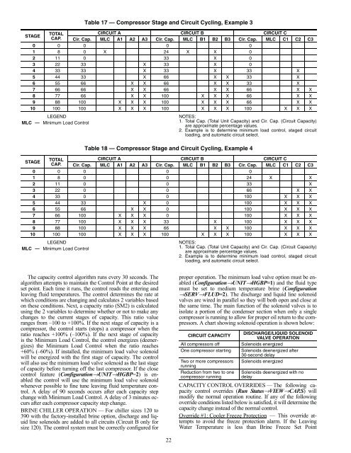
STAGETOTALCAP.LEGENDMLC — Minimum Load ControlLEGENDMLC — Minimum Load ControlTable 17 — Compressor Stage and Circuit Cycling, Example 3CIRCUIT A CIRCUIT B CIRCUIT CCir. Cap. MLC A1 A2 A3 Cir. Cap. MLC B1 B2 B3 Cir. Cap. MLC C1 C2 C30 0 0 0 01 8 0 X 24 X X 02 11 0 33 X 03 22 33 X 33 X 04 33 33 X 33 X 33 X5 44 33 X 66 X X 33 X6 55 66 X X 66 X X 33 X7 66 66 X X 66 X X 66 X X8 77 66 X X 100 X X X 66 X X9 88 100 X X X 100 X X X 66 X X10 100 100 X X X 100 X X X 100 X X XSTAGETOTALCAP.NOTES:1. Total Cap. (Total Unit Capacity) and Cir. Cap. (Circuit Capacity)are approximate percentage values.2. Example is to determine minimum load control, staged circuitloading, and automatic circuit select.Table 18 — Compressor Stage and Circuit Cycling, Example 4CIRCUIT A CIRCUIT B CIRCUIT CCir. Cap. MLC A1 A2 A3 Cir. Cap. MLC B1 B2 B3 Cir. Cap. MLC C1 C2 C30 0 0 0 01 8 0 0 24 X X2 11 0 0 33 X3 22 0 0 66 X X4 33 0 0 100 X X X5 44 33 X 0 100 X X X6 55 66 X X 0 100 X X X7 66 100 X X X 0 100 X X X8 77 100 X X X 33 X 100 X X X9 88 100 X X X 66 X X 100 X X X10 100 100 X X X 100 X X X 100 X X XNOTES:1. Total Cap. (Total Unit Capacity) and Cir. Cap. (Circuit Capacity)are approximate percentage values.2. Example is to determine minimum load control, staged circuitloading, and automatic circuit select.The capacity control algorithm runs every 30 seconds. Thealgorithm attempts to maintain the Control Point at the desiredset point. Each time it runs, the control reads the entering andleaving fluid temperatures. The control determines the rate atwhich conditions are changing and calculates 2 variables basedon these conditions. Next, a capacity ratio (SM2) is calculatedusing the 2 variables to determine whether or not to make anychanges to the current stages of capacity. This ratio valueranges from –100 to +100%. If the next stage of capacity is acompressor, the control starts (stops) a compressor when theratio reaches +100% (–100%). If the next stage of capacityis the Minimum Load Control, the control energizes (deenergizes)the Minimum Load Control when the ratio reaches+60% (–60%). If installed, the minimum load valve solenoidwill be energized with the first stage of capacity. The controlwill also use the minimum load valve solenoid as the last stageof capacity before turning off the last compressor. If the closecontrol feature (Configuration→UNIT→HGBP=2) is enabledthe control will use the minimum load valve solenoidwhenever possible to fine tune leaving fluid temperature control.A delay of 90 seconds occurs after each capacity stepchange with Minimum Load Control. A delay of 3 minutes occursafter each compressor capacity step change.BRINE CHILLER OPERATION — For chiller sizes 120 to390 with the factory-installed brine option, discharge and liquidline solenoids are added to all circuits (Circuit B only forsize 120). The control system must be correctly configured forproper operation. The minimum load valve option must be enabled(Configuration→UNIT→HGBP=1) and the fluid typemust be set to medium temperature brine (Configuration→SERV→FLUD=2). The discharge and liquid line solenoidvalves are wired in parallel so they will both open and close atthe same time. The main function of the solenoid valves is toisolate a portion of the condenser section when only a singlecompressor is running to allow for proper oil return to the compressors.A chart showing solenoid operation is shown below:CIRCUIT CAPACITYAll compressors offOne compressor startingTwo or more compressorsrunningReduction from two to onecompressor runningDISCHARGE/LIQUID SOLENOIDVALVE OPERATIONSolenoids energizedSolenoids deenergized after30-second delaySolenoids energizedSolenoids deenergized with nodelayCAPACITY CONTROL OVERRIDES — The following capacitycontrol overrides (Run Status→VIEW→CAP.S) willmodify the normal operation routine. If any of the followingoverride conditions listed below is satisfied, it will determine thecapacity change instead of the normal control.Override #1: Cooler Freeze Protection — This override attemptsto avoid the freeze protection alarm. If the LeavingWater Temperature is less than Brine Freeze Set Point22
(Configuration→SERV→LOSP) + 2.0° F (1.1º C) then removea stage of capacity.NOTE: The freeze set point is 34 F (1.1 C) for fresh watersystems (Configuration→SERV→FLUD=1). The freeze setpoint is Brine Freeze Set Point (Configuration→SERV→LOSP), for Medium Temperature Brine systems (Configuration→SERV→FLUD=2).Override #2: Circuit A Low Saturated Suction Temperaturein CoolingOverride #3: Circuit B Low Saturated Suction Temperaturein CoolingOverride #4: Circuit C Low Saturated Suction Temperaturein Cooling — These overrides attempt to avoid the low suctiontemperature alarms. This override is active only when morethan one compressor in a circuit is ON. If the Saturated SuctionTemperature is less than Brine Freeze Set Point (Configuration→SERV→LOSP)–18.0 F (–10 C) for 90 seconds, or theSaturated Suction Temperature is less than –4 F (–20 C), acompressor in the affected circuit will be turned off.Override #5: Low Temperature Cooling — This override removesone stage of capacity when the difference between theControl Point (Run Status→VIEW→CTPT) and the LeavingWater Temperature (Run Status→VIEW→LWT) reaches apredetermined limit and the rate of change of the water is 0 orstill decreasing.Override #6: Low Temperature Cooling — This override removestwo stages of capacity when the Entering WaterTemperature (Run Status→VIEW→EWT) is less than theControl Point (Run Status→VIEW→CTPT.)Override #7: Ramp Loading — If the unit is configured forramp loading (Configuration→OPTN→RL.S=ENBL) and ifthe difference between the Leaving Water Temperature and theControl Point is greater than 4º F (2.2º C) and the rate ofchange of the leaving water is greater than Cool Ramp LoadingRate (Setpoints→COOL→CRMP) then no capacity stageincrease will be made. Operating mode 5 (MD05) will be ineffect.Override #8: <strong>Service</strong> Manual Test Override — The manualtest consists in adding a stage of capacity every 30 seconds, untilthe control enables all of the requested compressors andMinimum Load Control selected in the ComfortLink display<strong>Service</strong> Test menu. All safeties and higher priority overridesare monitored and acted upon.Override # 9: Demand Limit — This override mode is activewhen a command to limit the capacity is received. If thecurrent unit capacity is greater than the active capacity limitvalue, a stage is removed. If the current capacity is lower thanthe capacity limit value, the control will not add a stage thatwill result in the new capacity being greater then the capacitylimit value. Operating mode 4 (MD04) will be in effect.Override #10: Cooler Interlock Override — This overrideprohibits compressor operation until the Cooler Interlock(Inputs→GEN.I→LOCK) is closed.Override #11: High Temperature Cooling — This overridealgorithm runs once when the unit is switched to ON. If the differencebetween the Leaving Water Temperature (Run Status→VIEW→LWT) and the Control Point (Run Status→VIEW→CTPT) exceeds a calculated value and the rate ofchange of the water temperature is greater than –0.1º F/min, astage will be added.Override #12: High Temperature Cooling — This overrideruns only when Minimum Load Control is Enabled, (Configuration→UNIT→HGBP)is 1, 2 or 3. This override will add astage of capacity if the next stage is Minimum Load Control,when the difference between the Leaving Water Temperature(Run Status→VIEW→LWT) and the Control Point (RunStatus→VIEW→CTPT) exceeds a calculated value and therate of change of the water temperature is greater than a fixedvalue.Override #13: Minimum On/Off and Off/On Time Delay —Whenever a capacity step change has been made, either withMinimum Load Control or a compressor, the control will remainat this capacity stage for the next 90 seconds. During thistime, no capacity control algorithm calculations will be made.If the capacity step is a compressor, an additional 90-seconddelay is added to the previous hold time (see Override #22).This override allows the system to stabilize before anothercapacity stage is added or removed. If a condition of a higherpriority override occurs, the higher priority override will takeprecedence.Override #14: Slow Change Override — This override preventscompressor stage changes when the leaving temperatureis close to the control point and slowly moving towards thecontrol point.Override #15: System Manager Capacity Control — If aChillervisor module is controlling the unit and the Chillervisormodule is controlling multiple chillers, the unit will add a stageto attempt to load to the demand limited value.Override #16: Circuit A High Pressure OverrideOverride #17: Circuit B High Pressure OverrideOverride #18: Circuit C High Pressure Override — This overrideattempts to avoid a high pressure failure. The algorithm isrun every 4 seconds. At least one compressor must be on in thecircuit. If the Saturated Condensing Temperature for the circuitis above the High Pressure Threshold (Configuration→SERV→HP.TH) then a compressor for that circuit willbe removed. If Minimum Load Control was enabled forHigh Ambient (Configuration→UNIT→HGBP=3), then theMinimum Control Valve will be energized.Override #19: Standby Mode — This override algorithm willnot allow a compressor to run if the unit is in Standby mode,(Run Status→VIEW→HC.ST=2).Override #22: Minimum On Time Delay — In addition toOverride #13 Minimum On/Off and Off/On Time Delay, forcompressor capacity changes, an additional 90-second delaywill be added to Override #13 delay. No compressor will bedeenergized until 3 minutes have elapsed since the last compressorhas been turned ON. When this override is active, thecapacity control algorithm calculations will be performed, butno capacity reduction will be made until the timer has expired.A control with higher precedence will override the MinimumOn Time Delay.Override #23: Circuit A Low Saturated SuctionTemperature in CoolingOverride #24: Circuit B Low Saturated SuctionTemperature in CoolingOverride #25: Circuit C Low Saturated SuctionTemperature in Cooling — If the circuit is operating in anarea close to the operational limit of the compressor, the circuitcapacity will remain at the same point or unload to raise the saturatedsuction temperature. This algorithm will be active if atleast one compressor in the circuit is on and one of the followingconditions is true:1. Saturated Suction Temperature is less than Brine Freeze(Configuration→SERV→LOSP) – 6º F (3.3º C).2. Saturated Suction Temperature is less than Brine Freeze(Configuration→SERV→LOSP) and the circuit approach(Leaving Water Temperature – Saturated SuctionTemperature) is greater than 15º F (8.3º C) and the CircuitSuperheat (Return Gas Temperature – Saturated SuctionTemperature) is greater than 15º F (8.3º C).NOTE: The freeze set point is 34 F (1.1 C) for freshwater systems (Configuration→SERV→FLUD=1). Thefreeze set point is Brine Freeze Set Point (Configuration→SERV→LOSP), for Medium Temperature Brinesystems (Configuration→SERV→FLUD=2).23