

Controls, Start-Up, Operation, Service And Troubleshooting - Carrier
Controls, Start-Up, Operation, Service And Troubleshooting - Carrier
Controls, Start-Up, Operation, Service And Troubleshooting - Carrier
- No tags were found...

You also want an ePaper? Increase the reach of your titles
YUMPU automatically turns print PDFs into web optimized ePapers that Google loves.
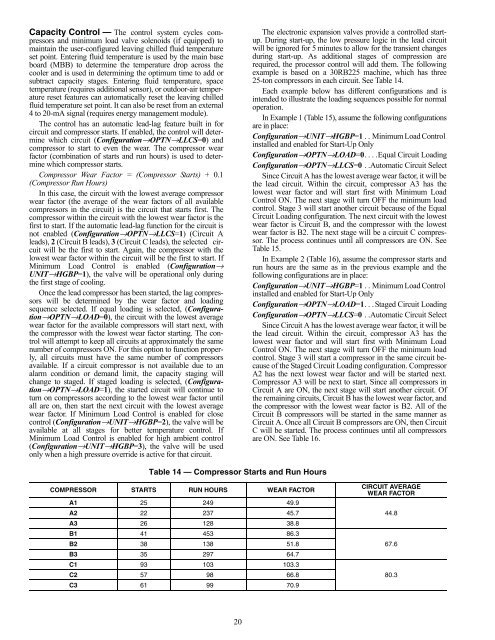
Capacity Control — The control system cycles compressorsand minimum load valve solenoids (if equipped) tomaintain the user-configured leaving chilled fluid temperatureset point. Entering fluid temperature is used by the main baseboard (MBB) to determine the temperature drop across thecooler and is used in determining the optimum time to add orsubtract capacity stages. Entering fluid temperature, spacetemperature (requires additional sensor), or outdoor-air temperaturereset features can automatically reset the leaving chilledfluid temperature set point. It can also be reset from an external4 to 20-mA signal (requires energy management module).The control has an automatic lead-lag feature built in forcircuit and compressor starts. If enabled, the control will determinewhich circuit (Configuration→OPTN→LLCS=0) andcompressor to start to even the wear. The compressor wearfactor (combination of starts and run hours) is used to determinewhich compressor starts.Compressor Wear Factor = (Compressor <strong>Start</strong>s) + 0.1(Compressor Run Hours)In this case, the circuit with the lowest average compressorwear factor (the average of the wear factors of all availablecompressors in the circuit) is the circuit that starts first. Thecompressor within the circuit with the lowest wear factor is thefirst to start. If the automatic lead-lag function for the circuit isnot enabled (Configuration→OPTN→LLCS=1) (Circuit Aleads), 2 (Circuit B leads), 3 (Circuit C leads), the selected circuitwill be the first to start. Again, the compressor with thelowest wear factor within the circuit will be the first to start. IfMinimum Load Control is enabled (Configuration→UNIT→HGBP=1), the valve will be operational only duringthe first stage of cooling.Once the lead compressor has been started, the lag compressorswill be determined by the wear factor and loadingsequence selected. If equal loading is selected, (Configuration→OPTN→LOAD=0),the circuit with the lowest averagewear factor for the available compressors will start next, withthe compressor with the lowest wear factor starting. The controlwill attempt to keep all circuits at approximately the samenumber of compressors ON. For this option to function properly,all circuits must have the same number of compressorsavailable. If a circuit compressor is not available due to analarm condition or demand limit, the capacity staging willchange to staged. If staged loading is selected, (Configuration→OPTN→LOAD=1),the started circuit will continue toturn on compressors according to the lowest wear factor untilall are on, then start the next circuit with the lowest averagewear factor. If Minimum Load Control is enabled for closecontrol (Configuration→UNIT→HGBP=2), the valve will beavailable at all stages for better temperature control. IfMinimum Load Control is enabled for high ambient control(Configuration→UNIT→HGBP=3), the valve will be usedonly when a high pressure override is active for that circuit.The electronic expansion valves provide a controlled startup.During start-up, the low pressure logic in the lead circuitwill be ignored for 5 minutes to allow for the transient changesduring start-up. As additional stages of compression arerequired, the processor control will add them. The followingexample is based on a 30RB225 machine, which has three25-ton compressors in each circuit. See Table 14.Each example below has different configurations and isintended to illustrate the loading sequences possible for normaloperation.In Example 1 (Table 15), assume the following configurationsare in place:Configuration→UNIT→HGBP=1 . . Minimum Load Controlinstalled and enabled for <strong>Start</strong>-<strong>Up</strong> OnlyConfiguration→OPTN→LOAD=0. . . .Equal Circuit LoadingConfiguration→OPTN→LLCS=0 . .Automatic Circuit SelectSince Circuit A has the lowest average wear factor, it will bethe lead circuit. Within the circuit, compressor A3 has thelowest wear factor and will start first with Minimum LoadControl ON. The next stage will turn OFF the minimum loadcontrol. Stage 3 will start another circuit because of the EqualCircuit Loading configuration. The next circuit with the lowestwear factor is Circuit B, and the compressor with the lowestwear factor is B2. The next stage will be a circuit C compressor.The process continues until all compressors are ON. SeeTable 15.In Example 2 (Table 16), assume the compressor starts andrun hours are the same as in the previous example and thefollowing configurations are in place:Configuration→UNIT→HGBP=1 . . Minimum Load Controlinstalled and enabled for <strong>Start</strong>-<strong>Up</strong> OnlyConfiguration→OPTN→LOAD=1. . . Staged Circuit LoadingConfiguration→OPTN→LLCS=0 . .Automatic Circuit SelectSince Circuit A has the lowest average wear factor, it will bethe lead circuit. Within the circuit, compressor A3 has thelowest wear factor and will start first with Minimum LoadControl ON. The next stage will turn OFF the minimum loadcontrol. Stage 3 will start a compressor in the same circuit becauseof the Staged Circuit Loading configuration. CompressorA2 has the next lowest wear factor and will be started next.Compressor A3 will be next to start. Since all compressors inCircuit A are ON, the next stage will start another circuit. Ofthe remaining circuits, Circuit B has the lowest wear factor, andthe compressor with the lowest wear factor is B2. All of theCircuit B compressors will be started in the same manner asCircuit A. Once all Circuit B compressors are ON, then CircuitC will be started. The process continues until all compressorsare ON. See Table 16.Table 14 — Compressor <strong>Start</strong>s and Run HoursCOMPRESSOR STARTS RUN HOURS WEAR FACTORA1 25 249 49.9A2 22 237 45.7A3 26 128 38.8B1 41 453 86.3B2 38 138 51.8B3 35 297 64.7C1 93 103 103.3C2 57 98 66.8C3 61 99 70.9CIRCUIT AVERAGEWEAR FACTOR44.867.680.320


