

Controls, Start-Up, Operation, Service And Troubleshooting - Carrier
Controls, Start-Up, Operation, Service And Troubleshooting - Carrier
Controls, Start-Up, Operation, Service And Troubleshooting - Carrier
- No tags were found...

You also want an ePaper? Increase the reach of your titles
YUMPU automatically turns print PDFs into web optimized ePapers that Google loves.
CONTENTS (cont)Page• COOLER LEAVING FLUID SENSOR• COOLER ENTERING FLUID SENSOR• DUAL CHILLER LWT• COMPRESSOR RETURN GAS TEMPERATURE• OUTDOOR AIR TEMPERATURE• REMOTE SPACE TEMPERATURE<strong>Service</strong> Test. . . . . . . . . . . . . . . . . . . . . . . . . . . . . . . . . . . . . . . . 74APPENDIX A — LOCAL DISPLAY TABLES . . . . . . 81-92APPENDIX B — CCN TABLES . . . . . . . . . . . . . . . . . . 93-106APPENDIX C — CCN ALARM DESCRIPTION . . 107-110APPENDIX D — R-410A PRESSURE VS.TEMPERATURE CHART. . . . . . . . . . . . . . . . . . . . . . . . . 111INDEX. . . . . . . . . . . . . . . . . . . . . . . . . . . . . . . . . . . . . . . . . .112,113START-UP CHECKLIST FOR 30RBLIQUID CHILLER . . . . . . . . . . . . . . . . . . . . . . . . CL-1 to CL-9SAFETY CONSIDERATIONSInstalling, starting up, and servicing this equipment can behazardous due to system pressures, electrical components, andequipment location (roof, elevated structures, etc.). Onlytrained, qualified installers and service mechanics shouldinstall, start up, and service this equipment. When working onthis equipment, observe precautions in the literature, and ontags, stickers, and labels attached to the equipment, and anyother safety precautions that apply. Follow all safety codes.Wear safety glasses and work gloves. Use care in handling,rigging, and setting this equipment, and in handling all electricalcomponents.Electrical shock can cause personal injury and death. Shutoff all power to this equipment during installation and service.There may be more than one disconnect switch. Tagall disconnect locations to alert others not to restore poweruntil work is completed.This unit uses a microprocessor-based electronic controlsystem. Do not use jumpers or other tools to short out components,or to bypass or otherwise depart from recommendedprocedures. Any short-to-ground of the controlboard or accompanying wiring may destroy the electronicmodules or electrical components.To prevent potential damage to heat exchanger tubes,always run fluid through heat exchanger when adding orremoving refrigerant charge. Use appropriate anti-freezesolutions in cooler fluid loop to prevent the freezing of heatexchanger, optional hydronic section and/or interconnectingpiping when the equipment is exposed to temperaturesbelow 32 F (0 °C). Proof of flow switch and strainer (whenhydronic kit is supplied) are factory installed on all models.Do NOT remove power from this chiller during winter shutdown periods without taking precaution to remove allwater from heat exchanger and optional hydronic system.Failure to properly protect the system from freezing mayconstitute abuse and may void warranty.Compressors and optional hydronic system pumps requirespecific rotation. Test condenser fan(s) first to ensureproper phasing. Swap any two incoming power leads tocorrect condenser fan rotation before starting any othermotors. Operating the unit without testing the condenserfan(s) for proper phasing could result in equipmentdamage.Refrigerant charge must be removed slowly to prevent lossof compressor oil that could result in compressor failure.DO NOT VENT refrigerant relief valves within a building.Outlet from relief valves must be vented in accordancewith the latest edition of ANSI/ASHRAE (AmericanNational Standards Institute/American Society of Heating,Refrigeration and Air Conditioning Engineers) 15 (SafetyCode for Mechanical Refrigeration). The accumulation ofrefrigerant in an enclosed space can displace oxygen andcause asphyxiation. Provide adequate ventilation inenclosed or low overhead areas. Inhalation of high concentrationsof vapor is harmful and may cause heart irregularities,unconsciousness or death. Misuse can be fatal. Vaporis heavier than air and reduces the amount of oxygen availablefor breathing. Product causes eye and skin irritation.Decomposition products are hazardous.DO NOT attempt to unbraze factory joints when servicingthis equipment. Compressor oil is flammable and there isno way to detect how much oil may be in any of the refrigerantlines. Cut lines with a tubing cutter as required whenperforming service. Use a pan to catch any oil that maycome out of the lines and as a gage for how much oil to addto system. DO NOT re-use compressor oil.This system uses Puron® refrigerant which has higherpressures than R-22 and other refrigerants. No other refrigerantcan be used in this system. Failure to use gage set,hoses, and recovery system designed to handle Puronrefrigerant may result in personal injury. If you are unsure,consult the equipment manufacturer.GENERALThis publication contains <strong>Controls</strong>, <strong>Operation</strong>, <strong>Start</strong>-<strong>Up</strong>,<strong>Service</strong> and <strong>Troubleshooting</strong> information for the 30RB060-390air-cooled liquid chillers with electronic controls. The 30RBchillers are equipped with ComfortLink controls andelectronic expansion valves.NOTE: Unit sizes 315-390 are modular units that are shippedin separate sections as modules A or B as noted in position 8 ofthe unit model number. Installation directions specific to theseunits are noted in these instructions. For modules 315A, 315B,330A, 330B, 345A, 345B, and 360B, follow all generalinstructions as noted for unit sizes 30RB160,170. For modules,360A, 390A, and 390B follow instructions for 30RB190. SeeTable 1 for a listing of unit sizes and modular combinations.NOTE: The nameplate for modular units contains only the firsttwo digits in the model number. For example, 315A and 315Bnameplates read 31A and 31B.2
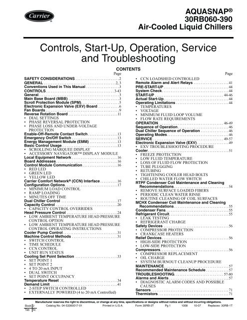
Table 1 — Modular Unit CombinationsUNIT SIZE MODULE A MODULE B30RBA315 30RBA160 30RBA16030RBA330 30RBA170 30RBA16030RBA345 30RBA170 30RBA17030RBA360 30RBA190 30RBA17030RBA390 30RBA190 30RBA190NOTE: An “A” in the model number indicates the design series.Conventions Used in This Manual — The followingconventions for discussing configuration points for thelocal display (scrolling marquee or Navigator accessory)will be used in this manual.Point names will be written with the mode name first, thenany sub-modes, then the point name, each separated by anarrow symbol (→). Names will also be shown in boldand italics. As an example, the Lead/Lag Circuit Select Point,which is located in the Configuration mode, Option sub-mode,would be written as Configuration →OPTN→LLCS.This path name will show the user how to navigate throughthe local display to reach the desired configuration. The userwould scroll through the modes and sub-modes using theand keys. The arrow symbol in the path name representspressing ENTER to move into the next level of themenu structure.When a value is included as part of the path name, it will beshown at the end of the path name after an equals sign. If thevalue represents a configuration setting, an explanation willbe shown in parenthesis after the value. As an example,Configuration→OPTN→LLCS = 1 (Circuit A leads).Pressing the ESCAPE and ENTER keys simultaneouslywill scroll an expanded text description of the point name orvalue across the display. The expanded description is shown inthe local display tables but will not be shown with the pathnames in text.The CCN (<strong>Carrier</strong> Comfort Network ® ) point names are alsoreferenced in the local display tables for users configuring theunit with CCN software instead of the local display. The CCNtables are located in Appendix B of the manual.CONTROLSGeneral — The 30RB air-cooled liquid chillers contain theComfortLink electronic control system that controls andmonitors all operations of the chiller. The control system iscomposed of several components as listed in the following sections.All machines have at the very least a main base board(MBB), scrolling marquee display, electric expansion valveboard (EXV), fan board, one scroll protection module (SPM)per compressor, Emergency On/Off switch, an Enable-Off- RemoteContact switch and a reverse rotation board.Main Base Board (MBB) — The MBB is the heart ofthe ComfortLink control system, which contains the majorportion of operating software and controls the operation of themachine. See Fig. 1. The MBB continuously monitors input/output channel information received from its inputs and fromall other modules. The MBB receives inputs from status andfeedback switches, pressure transducers and thermistors. TheMBB also controls several outputs. Some inputs and outputs tocontrol the machine are located on other boards, but are transmittedto or from the MBB via the internal communicationsbus. Information is transmitted between modules via a 3-wirecommunication bus or LEN (Local Equipment Network). TheCCN (<strong>Carrier</strong> Comfort Network) bus is also supported. Connectionsto both LEN and CCN buses are made at TB3. For acomplete description of main base board inputs and outputsand their channel identifications, see Table 2.STATUSSIO(LEN)+ G –+ G –+ G –J1A12/11 12/11J15J10MOV122122119 J12221221TR1 TR2 TR3 TR4 TR5C41 C42 C43C32 C33 C34 C35J2A J2B J2CRELAYOUTPUTSJ13 J9D+ G -CCND15K1 K2ANALOGJ3 INPUTSJ8195195J9C195J9B19519511195C16J4195J9ADISCRETEINPUTSJ5ATHERMISERS PRESSURESJ5BJ5CJ7A J7B J7C J7DJ6CH5 CH6 CH7 CH8 CH9CH1 CH2 CH3 CH4CH19 CH20 CH21 CH22 CH23 CH24 CH25 CH26CH10CH11 CH12CH13 CH14 CH15ACH15BCC16ACCH16BCH17CH18LOCATION OFSERIAL NUMBERFig. 1 — Main Base Board3
Table 2 — Main Base Board Inputs and OutputsDESCRIPTION INPUT/OUTPUT I/O TYPE* <strong>Controls</strong> discharge and liquid line isolation soleniods for 30RB120-190 brine units only.SCROLLING MARQUEEPOINT NAMEPower (24 vac supply) — — —Local Equipment Network — — —<strong>Carrier</strong> Comfort Network ®(CCN)— — —CONNECTION POINTPin NotationMBB-J1, MBB-J1A,MBB-J1B11 24 vac12 GroundMBB-J9A, MBB-J9B,MBB-J9C, MBB-J9D+G-MBB-J12+G-External ChilledWater Pump InterlockPMPI Switch INPUTS→GEN.I→LOCK MBB-J4-CH15AChilled Water Flow Switch CWFS Switch INPUTS→GEN.I→LOCKMBB-J5A-CH15B15BDemand Limit Switch #1 Demand Limit SW1 Switch INPUTS→GEN.I→DLS1 MBB-J4-CH13Circuit A DischargePressure TransducerCircuit B DischargePressure TransducerDPTADPTBPressure Transducer(0-5 VDC)Pressure Transducer(0-5 VDC)PRESSURE→PRC.A→DP.APRESSURE→PRC.B→DP.BMBB-J7A-CH65V 5 vdc Ref.S SignalR ReturnMBB-J7C-CH85V 5 vdc Ref.S SignalR ReturnDual ChillerLWT ThermistorDUAL 5k Thermistor TEMPERATURE→UNIT→CHWS MBB-J6-CH3Dual Set Point Input Dual Set Point Switch INPUTS→GEN.I→DUAL MBB-J4-CH12Entering Water Thermistor EWT 5k Thermistor TEMPERATURE→UNIT→EWT MBB-J6-CH2Leaving Water Thermistor LWT 5k Thermistor TEMPERATURE→UNIT→LWT MBB-J6-CH1Outdoor Air Thermistor OAT 5k Thermistor TEMPERATURE→UNIT→OAT MBB-J6-CH4MBB-J5C-CH18Pump #1 InterlockPMP1Pump #2 InterlockPMP2SwitchINPUTS→GEN.I→PUMP 18CReverse Rotation Board Reverse Rotation Board Switch INPUTS→GEN.I→ELECMBB-J5A-CH16B16BCircuit A SuctionPressure TransducerCircuit B SuctionPressure TransducerSPTASPTBPressure Transducer(0-5 VDC)Pressure Transducer(0-5 VDC)PRESSURE→PRC.A→SP.APRESSURE→PR.B→SP.BMBB-J7B-CH75V 5 vdc Ref.S SignalR ReturnMBB-J7D-CH95V 5 vdc Ref.S SignalR ReturnUnit Status Remote Contact-Off-Enable Switch INPUTS→GEN.I→ONOF MBB-J4-CH11Alarm Relay ALM R Relay OUTPUTS→GEN.O→ALRM MBB-J3-CH24Alert Relay ALT R Relay OUTPUTS→GEN.O→ALRT MBB-J3-CH25Cooler Heater CL-HT TRIAC OUTPUTS→GEN.O→CO.HT MBB-J2B-CH21Circuit A MinimumLoad Control*MLV-A TRIAC OUTPUTS→CIR.A→HGB.A MBB-J2C-CH22Circuit B MinimumLoad Control*MLV-B TRIAC OUTPUTS→CIR.B→HGB.B MBB-J2C-CH23Pump #1 <strong>Start</strong>er PMP1 TRIAC OUTPUTS→GEN.O→PMP.1 MBB-J2A-CH19Pump #2 <strong>Start</strong>er PMP2 TRIAC OUTPUTS→GEN.O→PMP.2 MBB-J2A-CH20Ready Relay RDY R Relay OUTPUTS→GEN.O→REDY MBB-J3-CH264
Scroll Protection Module (SPM) — There is oneSPM per compressor and it is responsible for controlling thatcompressor. See Fig. 2. The device controls the compressorcontactor and the compressor crankcase heater. The SPM modulealso monitors the compressor motor temperature, and circuithigh pressure switch. The SPM responds to commandsfrom the MBB (main base board) and sends the MBB theresults of the channels it monitors via the LEN (LocalEquipment Network). See below for SPM board address information.See Table 3 for SPM inputs and outputs.SPM-A1 DIPSwitch1 2 3 4 5 6 7 8Address: ON OFF OFF OFF ON OFF OFF OFFSPM-A2 DIPSwitch1 2 3 4 5 6 7 8Address: OFF ON OFF OFF ON OFF OFF OFFSPM-A3 DIPSwitch1 2 3 4 5 6 7 8Address: OFF OFF ON OFF ON OFF OFF OFFSPM-A4 DIPSwitch1 2 3 4 5 6 7 8Address: OFF OFF OFF ON ON OFF OFF OFFSPM-B1 DIPSwitch1 2 3 4 5 6 7 8Address: ON OFF OFF OFF OFF ON OFF OFFSPM-B2 DIPSwitch1 2 3 4 5 6 7 8Address: OFF ON OFF OFF OFF ON OFF OFFSPM-B3 DIPSwitch1 2 3 4 5 6 7 8Address: OFF OFF ON OFF OFF ON OFF OFFSPM-B4 DIPSwitch1 2 3 4 5 6 7 8Address: OFF OFF OFF ON OFF ON OFF OFFSPM-C1 DIPSwitch1 2 3 4 5 6 7 8Address: ON OFF OFF OFF OFF OFF ON OFFSPM-C2 DIPSwitch1 2 3 4 5 6 7 8Address: OFF ON OFF OFF OFF OFF ON OFFSPM-C3 DIPSwitch1 2 3 4 5 6 7 8Address: OFF OFF ON OFF OFF OFF ON OFFSPM-C4 DIPSwitch1 2 3 4 5 6 7 8Address: OFF OFF OFF ON OFF OFF ON OFFONLED1LED21031031 2 3 4 5 6 7 8JP3JP4 JP1JP2JP5JP6C19D4D6 D5Q4D7F1D9Q5U3QC1QC2Q6 D8 Q3C46D13 D14SMDFig. 2 — Scroll Protection Module5LOCATION OFSERIAL NUMBER
Table 3 — Scroll Protection Module Inputs and Outputs*DESCRIPTION INPUT/OUTPUT I/O TYPE* “x” denotes the circuit, A, B or C. “n” denotes the compressor number, 1, 2, 3, or 4.SCROLLING MARQUEEPOINT NAMEPower (24 vac supply) — — —Local Equipment Network — — —Circuit x High Pressure Switch HPS-x Switch Not availableCompressor xn Motor Temperature MTR-xn PTC Thermistor Not availableCompressor xn Contactor Cxn Relay OUTPUTS→CIR.x→CP.xnCrankcase Heater CCH Relay OUTPUTS→CIR.x→HT.xnCircuit x High Pressure Switch HPS-x Switch Not availableCONNECTION POINTPin NotationSPM-xn-J1QC1 24 vacQC2 GroundSPM-xn-JP11 +2 G3 -SPM-xn-JP22 +3 G4 -SPM-xn-JP312SPM-xn-JP412SPM-xn-JP512SPM-xn-JP612SPM-xn-JP21Electronic Expansion Valve (EXV) Board — Atleast one EXV board is used in all machines. There is one EXVboard for 2 circuit machines. Three circuit machines have twoEXV boards. See Fig. 3. The board is responsible for monitoringthe return gas temperature thermistors. The board alsosignals the EXV motors to open or close. The electronic expansionvalve board responds to commands from the MBB andsends the MBB the results of the channels it monitors via theLEN (local equipment network). See below for DIP switchinformation for EXV1 and EXV2. See Tables 4 and 5 for EXVinputs and outputs.EXV1 DIP Switch 1 2 3 4 5 6 7 8Address: ON ON ON ON ON ON OFF ONEXV2 DIP Switch 1 2 3 4 5 6 7 8Address: OFF ON ON ON ON ON OFF ON6
COMM J43 2 1- G +R3 L3 D1C49L2100KR2100100100R9TEMPJ3C25Q5Q4C39C37U1100KL1712D2U2C114 3 2 1THA THBU6SBS1Q7D15257-01D29D9STATUSD8SI0(LEN)1 2 3 4 5 6 7 8ONQ30C10Q10 Q12Q17 Q15Q20 Q22Q27 Q251 2 3 4 5 1 2 3 4 5J2A EXVA J2B EXVBQ2Q1U5U4L4G2Q37Q42D5Q35Q45LOCATION OFSERIAL NUMBERC16C15+C17D6D4MOV1J124VAC12/11Fig. 3 — EXV Board7
Table 4 — EXV1 Board Inputs and OutputsDESCRIPTION INPUT/OUTPUT I/O TYPESCROLLING MARQUEEPOINT NAMEPower (24 vac supply) — — —Local Equipment Network — — —Circuit A Suction Gas Thermistor SGTA 5k Thermistor TEMPERATURE→CIR.A→SGT.ACircuit B Suction Gas Thermistor SGTB 5k Thermistor TEMPERATURE→CIR.B→SGT.BCircuit A EXV EXV-A Stepper Motor OUTPUTS→CIR.A→EXV.ACircuit B EXV EXV-B Stepper Motor OUTPUTS→CIR.B→EXV.BCONNECTION POINTPin NotationEXV1-J111 24 vac12 GroundEXV1-J41 +2 G3 –EXV1-J3THAEXV1-J3THBEXV1-J2A1234EXV1-J2B1234Table 5 — EXV2 Inputs and OutputsDESCRIPTION INPUT/OUTPUT I/O TYPENOTE: EXV2 inputs and outputs are only used on 30RB210-300.SCROLLING MARQUEEPOINT NAMEPower (24 vac supply) — — —Local Equipment Network — —Circuit C Suction Gas Thermistor SGTC 5k Thermistor TEMPERATURE→CIR.C→SGT.CCircuit C EXV EXV-C Stepper Motor OUTPUTS→CIR.C→EXV.C—CONNECTION POINTPin NotationEXV2-J111 24 vac12 GroundEXV2-J41 +2 G3 –EXV2J3THAEXV2-J2A12348
Fan Boards — At least one fan board is installed in eachunit. See Fig. 4A and 4B. There are two types of fan boards,with and without an analog output signal for the low ambienthead pressure control fan speed controllers. If a unit does nothave low ambient head pressure control installed, it will nothave the analog connection terminals. The fan board respondsto commands from the MBB and sends the MBB the results ofthe channels it monitors via the LEN. See below for fan board1, 2 and 3 DIP switch addresses. See Tables 6-8 for inputs andoutputs.FAN BOARD 1DIP Switch1 2 3 4 5 6 7 8Address: OFF ON OFF OFF ON OFF ON OFFFAN BOARD 2DIP Switch1 2 3 4 5 6 7 8Address: ON ON OFF OFF ON OFF ON OFFFAN BOARD 3DIP Switch1 2 3 4 5 6 7 8Address: OFF OFF ON OFF ON OFF ON OFFLOCATION OFSERIAL NUMBERDIP SWITCHSTATUS SIO (LEN)24 VACJ1U2Q1D3U1ON1 2 3 4 5 6 7 8Q12S1Q60D8D7Q5Y1L5100KL3L2D5D6100K100KJ9– G +3 2 1U21U10Q11Q10U9U8U7U6U5– G +3 2 1U4JP2J2TR1 TR2 TR3 TR4 TR5 TR6 TR7 TR8J3J4C61CH13D12 JP1CH13 CH14CH1 CH2 CH3 CH4 CH5 CH6 CH7 CH8CH9 CH10 CH11 CH12Fig. 4A — Fan Board (AUX 1) with Low Ambient Temperature Head Pressure ControlLOCATION OFSERIAL NUMBERDIP SWITCHSTATUS SIO (LEN)D7Q5OND5S1J11 2 3 4 5 6 7 8Y1D6J924 VAC100K100K100KL2D3U1Q1Q12Q11Q10C3U9U8Q9Q3U6Q7Q2U5U2– G +3 2 1– G +3 2 1Q13D4J4J2TR1 TR2 TR3 TR4 TR5 TR6 TR7 TR8J3CH1 CH2 CH3 CH4 CH5 CH6 CH7 CH8Fig. 4B — Fan Board (AUX 2) without Low Ambient Temperature Head Pressure Control9
Table 6 — Fan Board 1 (AUX1, AUX2) Outputs*DESCRIPTION INPUT/OUTPUT I/O TYPESCROLLING MARQUEEPOINT NAMEPower (24 vac supply) — — —Local Equipment Network — — —Circuit A Low Ambient TemperatureHead Pressure Control Speed SignalCircuit B Low Ambient TemperatureHead Pressure Control Speed Signal(sizes 060-150, 210-250)Outdoor Fan Motor 1 OFM1 TRIACOutdoor Fan Motor 2 OFM2 TRIACOutdoor Fan Motor 3 OFM3 TRIACOutdoor Fan Motor 4 OFM4 TRIACOutdoor Fan Motor 5 OFM5 TRIACOutdoor Fan Motor 6 OFM6 TRIACOutdoor Fan Motor 7 OFM7 TRIACOutdoor Fan Motor 8 OFM8 TRIACMM-A† 0-10 VDC OUTPUTS→CIR.A→SPD.AMM-B† 0-10 VDC OUTPUTS→CIR.B→SPD.B*Fan boards 1 and 2 will use the AUX1 board when the low ambient temperature head pressure control option is installed.†Supplied on AUX1 board onlyNOTE: Fan Board 1 is used on 30RB060-390.CONNECTION POINTPin NotationFB1-J111 24 vac12 GroundFB1-J9+G-+G-FB1-CH9+-FB1-CH10+-FB1-J2-CH1(sizes 060-110)FB1-J2-CH2(sizes 120-150, 210-250)FB1-J2-CH3(sizes 160-190, 275, 300,315,390)FB1-J2-CH2(sizes 060-110)FB1-J2-CH3(sizes 120-150, 210-250)FB1-J2-CH4(sizes 160-190, 275, 300,315-390)FB1-J2-CH3(sizes 060, 070,090-110)FB1-J3-CH5(size 080)FB1-J2-CH1(sizes 120-150, 210-250)FB1-J2-CH2(sizes 160-190, 275, 300,315-390)FB1-J3-CH5(sizes 060, 070)FB1-J3-CH6(size 080)FB1-J3-CH7(sizes 090-110)FB1-J2-CH4(sizes 130, 150, 210-250)FB1-J3-CH6(sizes 160-190, 275-300,315-390)FB1-J3-CH5(sizes 090-110)FB1-J3-CH6(sizes 120-150, 210-250)FB1-J2-CH1(sizes 160-190, 275-300,315-390)FB1-J3-CH6(sizes 090-110, 160-190,275-300, 315-390)FB1-J3-CH7(sizes 120-150, 210-250)FB1-J3-CH5(sizes 120-150, 210-250)FB1-J3-CH8(sizes 120-150, 210-250)10
Table 7 — Fan Board 2 (AUX1, AUX2) Outputs*DESCRIPTION INPUT/OUTPUT I/O TYPESCROLLING MARQUEEPOINT NAMEPower (24 vac supply) — — —Local Equipment Network — — —Circuit B Low Ambient TemperatureHead Pressure ControlSpeed Signal(sizes 160-190, 275-300, 315-400)Outdoor Fan Motor 7 OFM7† TRIACOutdoor Fan Motor 8 OFM8 TRIACOutdoor Fan Motor 9 OFM9 TRIACOutdoor Fan Motor 10 OFM10 TRIACOutdoor Fan Motor 11 OFM11 TRIACOutdoor Fan Motor 12 OFM12 TRIACMM-B† 0-10 VDC OUTPUTS→CIR.B→SPD.B*Fan boards 1 and 2 will use the AUX1 board when the low ambient temperature head pressure control option is installed.†Output only on units with low ambient temperature head pressure control installed (AUX1).NOTE: Fan Board 2 used on 30RB160-190, 275-300, 315-390.CONNECTION POINTPinNotationFB2-J111 24 vac12 GroundFB2-J9+G-+G-FB2-CH9+-FB2-J2-CH2(sizes 160, 170, 315-345, 360B)FB2-J2-CH3(sizes 190, 275, 300, 360A, 390)FB2-J2-CH3(sizes 160, 170, 315-345, 360B)FB2-J2-CH4(sizes 190, 275, 300, 360A, 390)FB2-J2-CH1(sizes 160, 170, 315-345, 360B)FB2-J2-CH2(sizes 190, 275, 300, 360A, 390)FB2-J2-CH4(sizes 160, 170, 315-345, 360B)FB2-J3-CH5(sizes 190, 275, 300, 360A, 390)FB2-J2-CH1(sizes 190, 275-300, 360A, 390)FB2-J3-CH6(sizes 190, 275-300, 360A, 390)Reverse Rotation Board — The reverse rotationboard monitors the three-phase electrical system to providephase reversal, phase loss and under-voltage protection. SeeFig. 5. In addition, a 24-v time delay relay and contactor is usedto deenergize the entire control power of the chiller as part ofthe protection scheme. See Fig. 6. The reverse rotation boardhas two LEDs (light-emitting diodes) and two adjustable dialsettings. Under normal conditions, the upper LED will light upgreen. The lower LED is red and will flash (phase reversal) orturn on solid (phase loss and under-voltage) according to theconditions sensed.DIAL SETTINGS — The reverse rotation board has two dials.See Fig. 5. The upper dial should be set to match the incomingthree-phase voltage to the chiller with no compressorsrunning. This dial must be adjusted for 208/230-v chillers operatingon 208-v power supply. The dial should be adjusted to200-v minimum setting for this case. The lower dial is used fortrip delay and should be set fully counterclockwise to the minimum0.1 second setting. The time delay relay in the 24-v circuithas a delay setting as well and it should be set fully clockwiseto the maximum 1.0 second setting. See Fig. 6.PHASE REVERSAL PROTECTION — The control monitorsthe three-phase power sequence supplied at terminals L1,L2, and L3. If the control senses an incorrect phase relationship,the relay contacts (11/14) on the board will open. The relaycontacts will automatically reset when the correct phase sequenceis applied.PHASE LOSS AND UNDER-VOLTAGE PROTEC-TION — If the reverse rotation board senses that any one ofthe three phase inputs has no AC voltage or that any one phasehas dropped more than 20% below the voltage dial setting, therelay contacts (11/14) on the board will open. In addition,board relay contacts (21/24) will also open. If the contacts donot close within one second (time delay relay dial setting), the24-v control power to the chiller will be removed and all motoroutputs will be turned off. Control power will be restored automaticallywhen all three phases are present, in the correct sequenceand are within the limits of the voltage dial setting.LED STATUS<strong>Up</strong>per (green) LED on continuouslyLower (red) LED blinkingLower (red) LED on continuously<strong>Up</strong>per (green) LED offFUNCTIONRelay contacts closed (normaloperation)Relay contacts open (phase reversalhas occurred)Relay contacts open (phase lossor under-voltage has occurred)Power not present at L1, L2, L3(off)NOTE: Normal operation of the reverse rotation board (forexample, no faults are detected) results in a closed contactbeing applied to the MBB (plug J5A, channel 16B) through theclosed 11/14 relay contact.11
Table 8 — Fan Board 3 (AUX1) Inputs and OutputsDESCRIPTION INPUT/OUTPUT I/O TYPE*<strong>Controls</strong> discharge and liquid line isolation soleniods for 30RB210-300 brine units.†Low ambient temperature head pressure control output is on AUX1 board only.NOTE: Fan Board 3 used on 30RB210-300.SCROLLING MARQUEEPOINT NAMEPower (24 vac supply) — — —Local Equipment Network — — —Circuit C DischargePressure TransducerCircuit C SuctionPressure TransducerMinimum LoadValue Circuit CCircuit C Low AmbientTemperature Head PressureControl Speed Signal(sizes 210-300)DPTCSPTCPressure Transducer(0-5 VDC)Pressure Transducer(0-5 VDC)Outdoor Fan Motor 9 OFM9 TRIACOutdoor Fan Motor 10 OFM10 TRIACOutdoor Fan Motor 11 OFM11 TRIACOutdoor Fan Motor 12 OFM12 TRIACOutdoor Fan Motor 13 OFM13 TRIACOutdoor Fan Motor 14 OFM14 TRIACOutdoor Fan Motor 15 OFM15 TRIACOutdoor Fan Motor 16 OFM16 TRIACOutdoor Fan Motor 17 OFM17 TRIACOutdoor Fan Motor 18 OFM18 TRIACPRESSURE→PRC.C→DP.CPRESSURE→PRC.C→SP.CMLV-C* TRIAC OUTPUTS→CIR.C→HGB.CMM-C† 0-10 VDC OUTPUTS→CIR.C→SPD.CCONNECTION POINT(Unit Size)Pin NotationFB3-J111 24 vac12 GroundFB3-J9+G-+G-FB3-J7-CH13FB3-J8-CH14FB3-J3-CH7(sizes 210-300)FB3-CH9+-FB3-J2-CH2(sizes 210, 225)FB3-J2-CH3(size 250)FB3-J2-CH3(sizes 210, 225)FB3-J2-CH4(size 250)FB3-J2-CH1(sizes 210, 225)FB3-J2-CH2(size 250)FB3-J2-CH3(sizes 210, 225)FB3-J2-CH4(size 250)FB3-J2-CH1(size 250)FB3-J2-CH2(size 275)FB3-J2-CH3(size 300)FB3-J3-CH6(size 250)FB3-J2-CH3(size 275)FB3-J2-CH4(size 300)FB3-J2-CH1(size 275)FB3-J2-CH2(size 300)FB3-J2-CH4(size 275)FB3-J3-CH5(size 300)FB3-J2-CH1(size 300)FB3-J3-CH6(size 300)12
Enable-Off-Remote Contact Switch — This switchis installed in all units and provides the owner and serviceperson with a local means of enabling or disabling themachine. It is a 3-position switch used to control the chiller.When switched to the Enable position the chiller is under itsown control. Move the switch to the Off position to shut thechiller down. Move the switch to the Remote Contact positionand a field-installed dry contact can be used to start the chiller.The contacts must be capable of handling a 24-vac, 20-mAload. In the Enable and Remote Contact (dry contacts closed)positions, the chiller is allowed to operate and respond to thescheduling configuration, CCN configuration and set pointcontrol.Emergency On/Off Switch — This switch is installedin all units. The Emergency On/Off switch should only be usedwhen it is required to shut the chiller off immediately. Powerto the MBB, energy management module, and scrollingmarquee display is interrupted when this switch is off and alloutputs from these modules will be turned off.Energy Management Module (EMM) — The EMMis available as a factory-installed option or as a field-installedaccessory. The EMM receives 4 to 20 mA inputs for thetemperature reset, cooling set point reset and demand limitfunctions. The EMM also receives the switch inputs for thefield-installed second stage 2-step demand limit and ice donefunctions. The EMM communicates the status of all inputswith the MBB, and the MBB adjusts the control point, capacitylimit, and other functions according to the inputs received. SeeTable 9 and Fig. 7.Care should be taken when interfacing with other manufacturer’scontrol systems due to possible power supply differences,full wave bridge versus half wave rectification,which could lead to equipment damage. The two differentpower supplies cannot be mixed. ComfortLink controlsuse half wave rectification. A signal isolation device shouldbe utilized if incorporating a full wave bridge rectifier signalgenerating device is used.Basic Control UsageSCROLLING MARQUEE DISPLAY — The scrolling marqueedisplay is the standard interface display to the ComfortLinkControl System for 30RB units. The display has up and downarrow keys, an ENTER key, and an ESCAPE key. Thesekeys are used to navigate through the different levels of thedisplay structure. Press the ESCAPE key until the highestoperating level is displayed to move through the top 11 modelevels indicated by LEDs on the left side of the display. SeeFig. 8.Once within a mode or sub-mode, pressing the ENTERand ESCAPE keys simultaneously will put the scrollingmarquee display into expanded text mode where the full meaningof all sub-modes, items and their values can be displayedfor the current selection. Press the ENTER and ESCAPEkeys to return the scrolling marquee display to its default menuof rotating display items (those items in Run Status→VIEW).In addition, the password will be disabled, requiring that it beentered again before changes can be made to password protecteditems. Press the ESCAPE key to exit out of the expandedtext mode.Fig. 5 — Reverse Rotation Board (RRB)Fig. 6 — Time Delay Relay13
SIO LENSIO LEN+ G - + G -221221221221100K100K100K100KCH 5 CH 6 CH 7J8J7B100KJ7ACH12CH13CH14CH1CH15CH2CH3CH4J624 VAC12 11CH11bJ5CHCH17CH16CH17CH18CH19CH20CH21CH22CH23a30-4465J1J2AJ2BFig. 7 — Energy Management ModuleJ3J4* 250 ohm, 1/2 watt resistor required for 4-20 mA input.Table 9 — Energy Management Module (EMM) Inputs and OutputsINPUT DESCRIPTION I/O TYPE I/O POINT NAME CONNECTION POINT4-20 mA or 0-5 vdc Demand Limit 4-20 mA Demand Limit 0-5 vdc* INPUTS→GEN.I→DMND EMM-J7B-CH64-20 mA or 0-5 vdc Temperature Reset/Setpoint4-20 mA Temperature Reset/ 0-5 vdc* INPUTS→GEN.I→RSET EMM-J7A-CH5Set pointDemand Limit SW2 Demand Limit Step 2 Switch Input INPUTS→GEN.I→DLS2 EMM-J4-CH9Ice Done Ice Done Switch Switch Input INPUTS→GEN.I→ICE.D EMM-J4-CH11AOccupancy Override Occupied Schedule Override Switch Input INPUTS→GEN.I→OCCS EMM-J4-CH8Remote Lockout Switch Chiller Lockout Switch Input INPUTS→GEN.I→RLOC EMM-J4-CH10SPTSpace Temperature10k Thermistor TEMPERATURE→UNIT→SPT EMM-J6-CH2ThermistorOUTPUT DESCRIPTION I/O TYPE I/O POINT NAME CONNECTION POINT% Total Capacity 0-10 vdc OUTPUTS→GEN.O→CATO EMM-J8-CH7RUN R Run Relay Relay OUTPUTS→GEN.O→RUN EMM-J3-CH24SHD R Shutdown Relay Relay OUTPUTS→GEN.O→SHUT EMM-J3-CH25NOTE: When the Language Selection (Configuration→DISP→LANG), variable is changed, all appropriate displayexpansions will immediately change to the new language. Nopower-off or control reset is required when reconfiguringlanguages.When a specific item is located, the item name alternateswith the value. Press the ENTER key at a changeable itemand the value will be displayed. Press ENTER again and thevalue will begin to flash indicating that the value can bechanged. Use the up and down arrow keys to change the value,and confirm the value by pressing the ENTER key.MODERun Status<strong>Service</strong> TestTemperaturePressuresSetpointsInputsOutputsConfigurationTime ClockOperating ModesAlarmsAlarm StatusESCAPEENTERFig. 8 — Scrolling Marquee Display14
Changing item values or testing outputs is accomplished inthe same manner. Locate and display the desired item. PressENTER so that the item value flashes. Use the arrow keys tochange the value or state and press the ENTER key to acceptit. Press the ESCAPE key to return to the next higher level ofstructure. Repeat the process as required for other items.Items in the Configuration and <strong>Service</strong> Test modes are passwordprotected. The words ‘PASS’ and ‘WORD’ will alternateon the display when required. The default password is 0111.Press ENTER and the 1111 password will be displayed. PressENTER again and the first digit will begin to flash. Use thearrow keys to change the number and press ENTER to acceptthe digit. Continue with the remaining digits of the password.The password can only be changed through CCN operator interfacesoftware such as ComfortWORKS ® , ComfortVIEWand <strong>Service</strong> Tool.See Table 10 and Appendix A for further details.ACCESSORY NAVIGATOR DISPLAY MODULE —The Navigator module provides a mobile user interface to theComfortLink control system, which is only available as afield-installed accessory. The display has up and down arrowkeys, an ENTER key, and an ESCAPE key. These keys areused to navigate through the different levels of the displaystructure. Press the ESCAPE key until ‘Select a Menu Item’is displayed to move through the top 11 mode levels indicatedby LEDs on the left side of the display. See Fig. 9.Once within a Mode or sub-mode, a “>” indicates the currentlyselected item on the display screen. Pressing theENTER and ESCAPE keys simultaneously will put the Navigatormodule into expanded text mode where the full meaningof all sub-modes, items and their values can be displayed. Pressingthe ENTER and ESCAPE keys when the display says‘Select Menu Item’ (Mode LED level) will return the Navigatormodule to its default menu of rotating display items (those itemsin Run Status→VIEW). In addition, the password will be disabled,requiring that it be entered again before changes can bemade to password protected items. Press the ESCAPE key toexit out of the expanded text mode.NOTE: When the Language Selection (Configuration→DISP→LANG), variable is changed, all appropriate displayexpansions will immediately change to the new language. Nopower-off or control reset is required when reconfiguringlanguages.When a specific item is located, the item name appears on theleft of the display, the value will appear near the middle of thedisplay and the units (if any) will appear on the far right of thedisplay. Press the ENTER key at a changeable item and the valuewill begin to flash. Use the up and down arrow keys to changethe value, and confirm the value by pressing the ENTER key.Changing item values or testing outputs is accomplished inthe same manner. Locate and display the desired item. PressENTER so that the item value flashes. Use the arrow keys tochange the value or state and press the ENTER key to acceptit. Press the ESCAPE key to return to the next higher level ofstructure. Repeat the process as required for other items.Items in the Configuration and <strong>Service</strong> Test modes are passwordprotected. The words Enter Password will be displayedwhen required, with 1111 also being displayed. The defaultpassword is 0111. Use the arrow keys to change the numberand press ENTER to enter the digit. Continue with the remainingdigits of the password. The password can only bechanged through CCN operator interface software such asComfortWORKS, ComfortVIEW and <strong>Service</strong> Tool.Adjusting the Contrast — The contrast of the display can beadjusted to suit ambient conditions. To adjust the contrast ofthe Navigator module, press the ESCAPE key until the displayreads, “Select a menu item.” Using the arrow keys moveto the Configuration mode. Press ENTER to obtain access tothis mode. The display will read:> TEST OFFMETR OFFLANG ENGLISHPressing ENTER will cause the “OFF” to flash. Use the upor down arrow to change “OFF” to “ON”. Pressing ENTERwill illuminate all LEDs and display all pixels in the viewscreen. Pressing ENTER and ESCAPE simultaneouslyallows the user to adjust the display contrast. Use the up ordown arrows to adjust the contrast. The screen’s contrast willchange with the adjustment. Press ENTER to accept thechange. The Navigator module will keep this setting as long asit is plugged in to the LEN bus.Adjusting the Backlight Brightness — The backlight of thedisplay can be adjusted to suit ambient conditions. The factorydefault is set to the highest level. To adjust the backlight of theNavigator module, press the ESCAPE key until the displayreads, “Select a menu item.” Using the arrow keys move to theConfiguration mode. Press ENTER to obtain access to thismode. The display will read:> TEST OFFMETR OFFLANG ENGLISHPressing ENTER will cause the “OFF” to flash. Use the upor down arrow keys to change “OFF” to “ON”. PressingENTER will illuminate all LEDs and display all pixels in theview screen. Pressing the up and down arrow keys simultaneouslyallows the user to adjust the display brightness. Use theup or down arrow keys to adjust screen brightness. PressENTER to accept the change. The Navigator module willkeep this setting as long as it is plugged in to the LEN bus.Run Status<strong>Service</strong> TestTemperaturesPressuresSetpointsInputsOutputsConfigurationTime ClockOperating ModesAlarmsENTERComfortLinkMODE Alarm StatusESCFig. 9 — Accessory Navigator Display Module15
Table 10 — ComfortLink Display Menu StructureMODESETPOINTS INPUTS OUTPUTS CONFIGURATION TIMECLOCKRUNSTATUSAutoDisplay(VIEW)SERVICETESTManualTestMode(TEST)QuickTestMode(QUIC)TEMPERATURESPRESSURESOPERATINGMODESOperatingControlType(SLCT)OperatingModes(MODE)ALARMSUnitTemperatures(UNIT)Circuit APressures(PRC.A)CoolingSetpoints(COOL)GeneralInputs(GEN.I)Circuit AOutputs(CIR.A)DisplayConfiguration(DISP)Time of Day(TIME)ResetCurrentAlarms(R.ALM)CurrentAlarms(ALRM)RemoteUserInterface(R.CCN)Machine<strong>Start</strong>s/Hours(RUN)CompressorRun Hours(HOUR)Compressor<strong>Start</strong>s(STRT)Circuit ATemperatures(CIR.A)Circuit BPressures(PRC.B)HeatingSetpoints(HEAT)Circuit BOutputs(CIR.B)UnitConfiguration(UNIT)Day, Date(DATE)Circuit BTemperatures(CIR.B)Circuit CPressures(PRC.C)Misc.Setpoints(MISC)Circuit COutputs(CIR.C)<strong>Service</strong>Configurations(SERV)Schedule 1(SCH1)AlarmHistory(H.ALM)Circuit CTemperatures(CIR.C)GeneralOutputs(GEN.O)OptionsConfiguration(OPTN)Reset,Demand Limit,Master/Slave(RSET)Schedule 2(SCH2)Holidays(HOLI)Fan RunHours(FAN)<strong>Service</strong>MaintenanceConfiguration(MCFG)CompressorDisable(CP.UN)PredictiveMaintenance(MAIN)SoftwareVersions(VERS)Local Equipment Network — Information is transmittedbetween modules via a 3-wire communication bus orLEN (Local Equipment Network). External connection to theLEN bus is made at TB3.Board Addresses — All boards (except the main baseboard and the energy management module) have 8-positionDIP switches. Addresses for all boards are listed with the Input/Output Tables for each board.Control Module CommunicationRED LED — Proper operation of the control boards can bevisually checked by looking at the red status LEDs (lightemittingdiodes). When operating correctly, the red statusLEDs will blink in unison at a rate of once every 2 seconds. Ifthe red LEDs are not blink in unison, verify that correct poweris being supplied to all modules. Be sure that the main baseboard (MBB) is supplied with the current software. If necessary,reload current software. If the problem still persists,replace the MBB. A red LED that is lit continuously or blinkingat a rate of once per second or faster indicates that the boardshould be replaced.GREEN LED — All boards have a green LEN (SIO) LEDwhich should be blinking whenever power is on. If the LEDsare not blinking as described check LEN connections forpotential communication errors at the board connectors. SeeInput/Output Tables for LEN connector designations. A 3-wirebus accomplishes communication between modules. These3 wires run in parallel from module to module. The J9A connectoron the MBB provides communication directly to thescrolling marquee display or the Navigator display module.YELLOW LED — The MBB has one yellow LED. The<strong>Carrier</strong> Comfort Network ® (CCN) LED will blink during timesof network communication.<strong>Carrier</strong> Comfort Network (CCN) Interface — All30RB units can be connected to the CCN, if desired. The communicationbus wiring is a shielded, 3-conductor cable withdrain wire and is field supplied and installed. The system elementsare connected to the communication bus in a daisy chainarrangement. The positive pin of each system element communicationconnector must be wired to the positive pins of thesystem elements on either side of it, that is also required for thenegative and signal ground pins of each system element. Wiringconnections for CCN should be made at TB3. Consult theCCN Contractor’s Manual for further information. See Fig. 10.NOTE: Conductors and drain wire must be 20 AWG (AmericanWire Gage) minimum stranded, tinned copper. Individualconductors must be insulated with PVC, PVC/nylon, vinyl,Teflon, or polyethylene. An aluminum/polyester 100% foilshield and an outer jacket of PVC, PVC/nylon, chrome vinyl,or Teflon with a minimum operating temperature range of–20 C to 60 C is required. See Table 11 for recommended wiremanufacturers and part numbers.Fig. 10 — ComfortLink CCN Communication Wiring16
Table 11 — CCN Communication Bus WiringMANUFACTURERPART NUMBERRegular Wiring Plenum WiringAlpha 1895 —American A21451 A48301Belden 8205 884421Columbia D6451 —Manhattan M13402 M64430Quabik 6130 —It is important when connecting to a CCN communicationbus that a color-coding scheme be used for the entire networkto simplify the installation. It is recommended that red be usedfor the signal positive, black for the signal negative, and whitefor the signal ground. Use a similar scheme for cables containingdifferent colored wires.At each system element, the shields of its communicationbus cables must be tied together. If the communication bus isentirely within one building, the resulting continuous shieldmust be connected to a ground at one point only. If the communicationbus cable exits from one building and enters another,the shields must be connected to grounds at the lightningsuppressor in each building where the cable enters or exits thebuilding (one point per building only). To connect the unit tothe network:1. Turn off power to the control box.2. Cut the CCN wire and strip the ends of the red (+), white(ground), and black (–) conductors. (Substitute appropriatecolors for different colored cables.)3. Connect the red wire to (+) terminal on TB3 of the plug,the white wire to COM terminal, and the black wire to the(–) terminal.4. The RJ14 CCN connector on TB3 can also be used, but isonly intended for temporary connection (for example, alaptop computer running <strong>Service</strong> Tool).IMPORTANT: A shorted CCN bus cable will preventsome routines from running and may prevent the unitfrom starting. If abnormal conditions occur, disconnectthe CCN bus. If conditions return to normal,check the CCN connector and cable. Run new cable ifnecessary. A short in one section of the bus can causeproblems with all system elements on the bus.Configuration OptionsMINIMUM LOAD CONTROL (Configuration→UNIT→HGBP) reduces the capacity of the 30RB chiller below thelowest standard capacity step by use of hot gas bypass. Thiscapacity step reduction provides more precise control of theleaving water temperature.Minimum Load Control can be configured in three differentways. If Minimum Load Control is not used, HGBP must beset 0. If HGBP is set to 1, the control will activate the minimumload control valve when the machine is started only. Thiswill be the first step of capacity. If HGBP is set to 2, all stagesof capacity can utilize the minimum load control valve. IfHGBP is set to 3, the minimum load control valve will be usedonly when the circuit has a high pressure override active. Thiswill reduce the capacity of the circuit.RAMP LOADING (Configuration→OPTN→RL.S), limitsthe rate of change of leaving fluid temperature. If the unit is ina Cooling mode and configured for Ramp Loading, the controlmakes 2 comparisons before deciding to change stages ofcapacity. The control calculates a temperature differencebetween the control point and leaving fluid temperature. If thedifference is greater than 4° F (2.2° C) and the rate of change(°F or °C per minute) is more than the configured Cool RampLoading (Setpoints→COOL→CRMP), the control does notallow any changes to the current stage of capacity.MINUTES OFF TIME (Configuration→OPTN→ DELY) isa time delay added to the start when the machine is commandedON. This is a field configurable item from 1 to15 minutes. The factory default is 1 minute. This feature isuseful when multiple units are installed. Staggering the startwill reduce the inrush potential.Dual Chiller Control — The dual chiller routine isavailable for the control of two parallel units supplying chilledfluid on a common loop. This control is designed for a parallelfluid flow arrangement only. One chiller must be configured asthe master chiller, the other as the slave chiller. An additionalleaving fluid temperature thermistor (Dual Chiller LWT) mustbe installed in the common chilled water piping as described inthe Installation Instructions for both the master and slavechillers. See the Field Wiring section in the 30RB InstallationInstructions for dual chiller LWT sensor control wiring. Achilled water flow switch is factory-installed for each chiller.Parallel chiller control with dedicated pumps is recommended.Chiller must start and stop its own water pump locatedon its own piping. If pumps are not dedicated for eachchiller, chiller isolation valves are required: each chiller mustopen and close its own isolation valve through the control(valve shall be connected to the pump outputs). Pump Controlis enabled as described in the Cooler Pump Control section onpage 31. One additional parameter is set for the dual chillercontrol. Lag Unit Pump Select, (Configuration→RSET→LAGP) allows the user to configure the control to energizethe pump for the lag chiller once the unit enters an occupiedtime period or delay the control until the lag chiller is started. Itis recommended that this parameter be set to 0, OFF IF UNITSTOPPED.The control of the slave chiller is directed through commandsemitted by the master chiller. The slave chiller has noaction in master/slave operations it shall only verify that CCNcommunication with its master is present. See the Dual ChillerSequence of <strong>Operation</strong> section on page 46.Use dual chiller control to designate a lead chiller betweenthe master and slave chiller. Configure the Lead/Lag BalanceSelect (Configuration→RSET→LLBL) to ENBL to base theselection on the Lead/Lag Balance Delta (Configuration→RSET→LLBD) between the master and slave run hours. Ifthe run hour difference between the master and the slaveremains less than LLBD, the chiller designated as the lead willremain the lead chiller. The Lead/Lag changeover between themaster and the slave chiller due to hour balance will occur duringchiller operating odd days, such as day 1, day 3, and day 5of the month, at 12:00 a.m. If a lead chiller is not designated,the master chiller will always be designated the lead chiller.The dual chiller control algorithm has the ability to delaythe start of the lag chiller in two ways. The Lead PulldownTime (Configuration→RSET→LPUL) provides a field configurabletime delay of 0 to 60 minutes. This time delay givesthe lead chiller a chance to remove the heat that the chilled waterloop picked up while being inactive during an unoccupiedperiod. The Lead Pulldown Time parameter is a one-time timedelay initiated after starting the lead chiller, manually or by aschedule, before checking whether to start an additional chiller.This routine provides the lead chiller an opportunity to pulldown the loop temperature before starting another chiller. Thesecond time delay, Lead/Lag Delay (Configuration→RSET→LLDY) is a time delay imposed between the laststage of the lead chiller and the start of the lag chiller. This preventsenabling the lag chiller until the lead/lag delay timer hasexpired. See Tables 12 and 13.17
Table 12 — Configuring the Master ChillerMODE KEYPAD ENTRY DISPLAY ITEM EXPANSION COMMENTCONFIGURATIONENTERDISPUNITSERVENTERENTERESCAPEENTERESCAPEESCAPEOPTNCCNA CCN AddressConfirm address of chiller. The master and slave chillermust have different addresses.1 Factory default address is 1.CCNACCNB CCN Bus NumberConfirm the bus number of the chiller. The master and slavechiller must be on the same bus.0 Factory default is 0.CCNBOPTNENTERRSETCRSTReset Cool and Heat TmpCooling Reset Typex 5 MSSL Master/Slave SelectENTERENTER0 Disable0 Disable Flashing to indicate Edit mode. May require Password.1 Master Use up arrows to change value to 1.ENTERESCAPE1 Accepts the change.MSSLSLVASlave AddressENTERENTERENTERESCAPE11 Flashing to indicate Edit mode.Use up arrows to change value to 2. This address must2match the address of the slave chiller.2 Accepts the change.SLVALLBLLead/Lag Balance SelectENTERESCAPEENBLLLBLFactory Default is ENBLLLBDLead/Lag Balance DeltaENTERESCAPE168 Factory Default is 168.LLBDLLDYLead/Lag <strong>Start</strong> DelayENTERESCAPE10 Factory Default is 10.LLDYLAGPLag Unit Pump SelectENTERESCAPE0 Off if U Stp Factory Default is 0, Off if unit is stopped.LAGPLPULLead Pulldown TimeENTER0 Factory Default is 0.ESCAPEESCAPEAt mode level.OPERATINGMODESENTERENTERESCAPEOPEROperating Control Type0 Switch ControlMaster chiller should be configured for job requirements,Switch Control, Time Schedule, or CCN.At mode level.NOTE: Bold values indicate sub-mode level.18
Table 13 — Configuring the Slave ChillerMODE KEYPAD ENTRY DISPLAY ITEM EXPANSION COMMENTCONFIGURATIONENTERDISPUNITSERVOPTNENTERENTERENTERCCNA CCN Address Confirm address of chiller. The master and slave chillermust have different addresses.1 Factory default address is 1. The slave chiller addressmust match what was programmed in the Master ChillerSLVA item.1 Flashing to indicate Edit Mode.2 This item must match Master Chiller SLVA item.ENTERESCAPEENTERESCAPEESCAPE2 Accepts the change.CCNACCNB CCN Bus Number Confirm the bus number of the chiller. The master andslave chiller must be on the same bus.0 Factory default bus number is 0.CCNBOPTNENTERRSETCRSTReset Cool and Heat TmpCooling Reset Typex 5 MSSL Master/Slave SelectENTERENTER0 Disable0 Disable Flashing to indicate Edit mode. May require Password2 Slave Use up arrows to change value to 2.ENTERESCAPE2 Accepts the change.MSSLSLVA Slave Address Not required.LLBL Lead/Lag Balance Select Not required.LLBD Lead/Lag Balance Delta Not required.LLDY Lead/Lag <strong>Start</strong> Delay Not required.LAGP Lag Unit Pump Select Not required.LPUL Lead Pulldown Time Not required.ESCAPEESCAPEAt mode levelOPERATING MODES ENTEROPER Operating Control TypeENTERENTERENTERESCAPEESCAPE0 Switch Control0 Flashing to indicate Edit Mode.2 CCN Control Use up arrows to change value to 2.NOTE: Slave chiller must be configured for CCN.2 Accepts the value.OPERAt mode levelNOTE: Bold values indicate sub-mode level.19
Capacity Control — The control system cycles compressorsand minimum load valve solenoids (if equipped) tomaintain the user-configured leaving chilled fluid temperatureset point. Entering fluid temperature is used by the main baseboard (MBB) to determine the temperature drop across thecooler and is used in determining the optimum time to add orsubtract capacity stages. Entering fluid temperature, spacetemperature (requires additional sensor), or outdoor-air temperaturereset features can automatically reset the leaving chilledfluid temperature set point. It can also be reset from an external4 to 20-mA signal (requires energy management module).The control has an automatic lead-lag feature built in forcircuit and compressor starts. If enabled, the control will determinewhich circuit (Configuration→OPTN→LLCS=0) andcompressor to start to even the wear. The compressor wearfactor (combination of starts and run hours) is used to determinewhich compressor starts.Compressor Wear Factor = (Compressor <strong>Start</strong>s) + 0.1(Compressor Run Hours)In this case, the circuit with the lowest average compressorwear factor (the average of the wear factors of all availablecompressors in the circuit) is the circuit that starts first. Thecompressor within the circuit with the lowest wear factor is thefirst to start. If the automatic lead-lag function for the circuit isnot enabled (Configuration→OPTN→LLCS=1) (Circuit Aleads), 2 (Circuit B leads), 3 (Circuit C leads), the selected circuitwill be the first to start. Again, the compressor with thelowest wear factor within the circuit will be the first to start. IfMinimum Load Control is enabled (Configuration→UNIT→HGBP=1), the valve will be operational only duringthe first stage of cooling.Once the lead compressor has been started, the lag compressorswill be determined by the wear factor and loadingsequence selected. If equal loading is selected, (Configuration→OPTN→LOAD=0),the circuit with the lowest averagewear factor for the available compressors will start next, withthe compressor with the lowest wear factor starting. The controlwill attempt to keep all circuits at approximately the samenumber of compressors ON. For this option to function properly,all circuits must have the same number of compressorsavailable. If a circuit compressor is not available due to analarm condition or demand limit, the capacity staging willchange to staged. If staged loading is selected, (Configuration→OPTN→LOAD=1),the started circuit will continue toturn on compressors according to the lowest wear factor untilall are on, then start the next circuit with the lowest averagewear factor. If Minimum Load Control is enabled for closecontrol (Configuration→UNIT→HGBP=2), the valve will beavailable at all stages for better temperature control. IfMinimum Load Control is enabled for high ambient control(Configuration→UNIT→HGBP=3), the valve will be usedonly when a high pressure override is active for that circuit.The electronic expansion valves provide a controlled startup.During start-up, the low pressure logic in the lead circuitwill be ignored for 5 minutes to allow for the transient changesduring start-up. As additional stages of compression arerequired, the processor control will add them. The followingexample is based on a 30RB225 machine, which has three25-ton compressors in each circuit. See Table 14.Each example below has different configurations and isintended to illustrate the loading sequences possible for normaloperation.In Example 1 (Table 15), assume the following configurationsare in place:Configuration→UNIT→HGBP=1 . . Minimum Load Controlinstalled and enabled for <strong>Start</strong>-<strong>Up</strong> OnlyConfiguration→OPTN→LOAD=0. . . .Equal Circuit LoadingConfiguration→OPTN→LLCS=0 . .Automatic Circuit SelectSince Circuit A has the lowest average wear factor, it will bethe lead circuit. Within the circuit, compressor A3 has thelowest wear factor and will start first with Minimum LoadControl ON. The next stage will turn OFF the minimum loadcontrol. Stage 3 will start another circuit because of the EqualCircuit Loading configuration. The next circuit with the lowestwear factor is Circuit B, and the compressor with the lowestwear factor is B2. The next stage will be a circuit C compressor.The process continues until all compressors are ON. SeeTable 15.In Example 2 (Table 16), assume the compressor starts andrun hours are the same as in the previous example and thefollowing configurations are in place:Configuration→UNIT→HGBP=1 . . Minimum Load Controlinstalled and enabled for <strong>Start</strong>-<strong>Up</strong> OnlyConfiguration→OPTN→LOAD=1. . . Staged Circuit LoadingConfiguration→OPTN→LLCS=0 . .Automatic Circuit SelectSince Circuit A has the lowest average wear factor, it will bethe lead circuit. Within the circuit, compressor A3 has thelowest wear factor and will start first with Minimum LoadControl ON. The next stage will turn OFF the minimum loadcontrol. Stage 3 will start a compressor in the same circuit becauseof the Staged Circuit Loading configuration. CompressorA2 has the next lowest wear factor and will be started next.Compressor A3 will be next to start. Since all compressors inCircuit A are ON, the next stage will start another circuit. Ofthe remaining circuits, Circuit B has the lowest wear factor, andthe compressor with the lowest wear factor is B2. All of theCircuit B compressors will be started in the same manner asCircuit A. Once all Circuit B compressors are ON, then CircuitC will be started. The process continues until all compressorsare ON. See Table 16.Table 14 — Compressor <strong>Start</strong>s and Run HoursCOMPRESSOR STARTS RUN HOURS WEAR FACTORA1 25 249 49.9A2 22 237 45.7A3 26 128 38.8B1 41 453 86.3B2 38 138 51.8B3 35 297 64.7C1 93 103 103.3C2 57 98 66.8C3 61 99 70.9CIRCUIT AVERAGEWEAR FACTOR44.867.680.320
LEGENDMLC — Minimum Load ControlLEGENDMLC — Minimum Load ControlTable 15 — Compressor Stages and Circuit Cycling, Example 1STAGECIRCUIT A CIRCUIT B CIRCUIT CTOTALCAP. Cir.MLC A1 A2 A3Cir.MLC B1 B2 B3Cir.MLC C1 C2 C3Cap.Cap.Cap.0 0 0 0 01 8 24 X X 0 02 11 33 X 0 03 22 33 X 33 X 04 33 33 X 33 X 33 X5 44 66 X X 33 X 33 X6 55 66 X X 66 X X 33 X7 66 66 X X 66 X X 66 X X8 77 100 X X X 66 X X 66 X X9 88 100 X X X 100 X X X 66 X X10 100 100 X X X 100 X X X 100 X X XNOTES:1. Total Cap. (Total Unit Capacity) and Cir. Cap. (Circuit Capacity)are approximate percentage values.2. Example is to determine minimum load control, staged circuitloading, and automatic circuit select.Table 16 — Compressor Stage and Circuit Cycling, Example 2STAGECIRCUIT A CIRCUIT B CIRCUIT CTOTOLCAP. Cir.MLC A1 A2 A3Cir.MLC B1 B2 B3Cir.MLC C1 C2 C3Cap.Cap.Cap.0 0 0 0 01 8 24 X X 0 02 11 33 X 0 03 22 66 X X 0 04 33 100 X X X 0 05 44 100 X X X 33 X 06 55 100 X X X 66 X X 07 66 100 X X X 100 X X X 08 77 100 X X X 100 X X X 33 X9 88 100 X X X 100 X X X 66 X X10 100 100 X X X 100 X X X 100 X X XNOTES:1. Total Cap. (Total Unit Capacity) and Cir. Cap. (Circuit Capacity)are approximate percentage values.2. Example is to determine minimum load control, staged circuitloading, and automatic circuit select.In Example 3 (Table 17), assume the following configurationsare in place:Configuration→UNIT→HGBP=1. . Minimum Load Controlinstalled and enabled for <strong>Start</strong>-<strong>Up</strong> OnlyConfiguration→OPTN→LOAD=0 . . .Equal Circuit LoadingConfiguration→OPTN→LLCS=2 . . . . . . . . . Circuit B LeadsSince Circuit B has been selected, it will be the lead circuit.Within the circuit, compressor B2 has the lowest wear factorand will start first with Minimum Load Control ON. The nextstage will turn OFF the minimum load control. Stage 3 willstart another circuit because of the Equal Circuit Loadingconfiguration. Comparing Circuit A and C, the circuit with thelowest average wear factor is Circuit A, and the compressorwith the lowest wear factor is A3. The next stage will be acircuit C compressor. The process continues until all compressorsare ON. See Table 17.In Example 4 (Table 18), assume the compressor starts andrun hours are the same as in the first example and the followingconfigurations are in place:Configuration→UNIT→HGBP=1. . Minimum Load Controlinstalled and enabled for <strong>Start</strong>-<strong>Up</strong> OnlyConfiguration→OPTN→LOAD=1 . . Staged Circuit LoadingConfiguration→OPTN→LLCS=3 . . . . . . . . . Circuit C LeadsSince Circuit C has been selected, it will be the lead circuit.Within the circuit, compressor C2 has the lowest wear factorand will start first with Minimum Load Control ON. The nextstage will turn OFF the minimum load control. Stage 3 willstart a compressor in the same circuit because of the StagedCircuit Loading configuration. Compressor C3 has the nextlowest wear factor and will be started next. Compressor C1will be next to start. Since all compressors in Circuit C are ON,the next stage will start another circuit. Of the remaining circuits,Circuit A has the lowest wear factor, and the compressorwith the lowest wear factor is A3. All of the Circuit A compressorswill be started in the same manner as Circuit C. Onceall Circuit A compressors are ON, then Circuit B will be started.The process continues until all compressors are ON. SeeTable 18.If the circuit capacity is to be reduced, the compressor withthe highest wear factor will be shut off first (in most cases).With Equal Circuit Loading, stages will be removed from eachcircuit, following the same criteria used in the loadingsequence, but in the opposite order. Shown in Table 18 basedon the current wear factor in the opposite to the loadingsequence shown above, the compressor with the highest wearfactor will be removed first. When Staged Circuit Loading isselected, the capacity from the last lag circuit will be removedfirst.21
STAGETOTALCAP.LEGENDMLC — Minimum Load ControlLEGENDMLC — Minimum Load ControlTable 17 — Compressor Stage and Circuit Cycling, Example 3CIRCUIT A CIRCUIT B CIRCUIT CCir. Cap. MLC A1 A2 A3 Cir. Cap. MLC B1 B2 B3 Cir. Cap. MLC C1 C2 C30 0 0 0 01 8 0 X 24 X X 02 11 0 33 X 03 22 33 X 33 X 04 33 33 X 33 X 33 X5 44 33 X 66 X X 33 X6 55 66 X X 66 X X 33 X7 66 66 X X 66 X X 66 X X8 77 66 X X 100 X X X 66 X X9 88 100 X X X 100 X X X 66 X X10 100 100 X X X 100 X X X 100 X X XSTAGETOTALCAP.NOTES:1. Total Cap. (Total Unit Capacity) and Cir. Cap. (Circuit Capacity)are approximate percentage values.2. Example is to determine minimum load control, staged circuitloading, and automatic circuit select.Table 18 — Compressor Stage and Circuit Cycling, Example 4CIRCUIT A CIRCUIT B CIRCUIT CCir. Cap. MLC A1 A2 A3 Cir. Cap. MLC B1 B2 B3 Cir. Cap. MLC C1 C2 C30 0 0 0 01 8 0 0 24 X X2 11 0 0 33 X3 22 0 0 66 X X4 33 0 0 100 X X X5 44 33 X 0 100 X X X6 55 66 X X 0 100 X X X7 66 100 X X X 0 100 X X X8 77 100 X X X 33 X 100 X X X9 88 100 X X X 66 X X 100 X X X10 100 100 X X X 100 X X X 100 X X XNOTES:1. Total Cap. (Total Unit Capacity) and Cir. Cap. (Circuit Capacity)are approximate percentage values.2. Example is to determine minimum load control, staged circuitloading, and automatic circuit select.The capacity control algorithm runs every 30 seconds. Thealgorithm attempts to maintain the Control Point at the desiredset point. Each time it runs, the control reads the entering andleaving fluid temperatures. The control determines the rate atwhich conditions are changing and calculates 2 variables basedon these conditions. Next, a capacity ratio (SM2) is calculatedusing the 2 variables to determine whether or not to make anychanges to the current stages of capacity. This ratio valueranges from –100 to +100%. If the next stage of capacity is acompressor, the control starts (stops) a compressor when theratio reaches +100% (–100%). If the next stage of capacityis the Minimum Load Control, the control energizes (deenergizes)the Minimum Load Control when the ratio reaches+60% (–60%). If installed, the minimum load valve solenoidwill be energized with the first stage of capacity. The controlwill also use the minimum load valve solenoid as the last stageof capacity before turning off the last compressor. If the closecontrol feature (Configuration→UNIT→HGBP=2) is enabledthe control will use the minimum load valve solenoidwhenever possible to fine tune leaving fluid temperature control.A delay of 90 seconds occurs after each capacity stepchange with Minimum Load Control. A delay of 3 minutes occursafter each compressor capacity step change.BRINE CHILLER OPERATION — For chiller sizes 120 to390 with the factory-installed brine option, discharge and liquidline solenoids are added to all circuits (Circuit B only forsize 120). The control system must be correctly configured forproper operation. The minimum load valve option must be enabled(Configuration→UNIT→HGBP=1) and the fluid typemust be set to medium temperature brine (Configuration→SERV→FLUD=2). The discharge and liquid line solenoidvalves are wired in parallel so they will both open and close atthe same time. The main function of the solenoid valves is toisolate a portion of the condenser section when only a singlecompressor is running to allow for proper oil return to the compressors.A chart showing solenoid operation is shown below:CIRCUIT CAPACITYAll compressors offOne compressor startingTwo or more compressorsrunningReduction from two to onecompressor runningDISCHARGE/LIQUID SOLENOIDVALVE OPERATIONSolenoids energizedSolenoids deenergized after30-second delaySolenoids energizedSolenoids deenergized with nodelayCAPACITY CONTROL OVERRIDES — The following capacitycontrol overrides (Run Status→VIEW→CAP.S) willmodify the normal operation routine. If any of the followingoverride conditions listed below is satisfied, it will determine thecapacity change instead of the normal control.Override #1: Cooler Freeze Protection — This override attemptsto avoid the freeze protection alarm. If the LeavingWater Temperature is less than Brine Freeze Set Point22
(Configuration→SERV→LOSP) + 2.0° F (1.1º C) then removea stage of capacity.NOTE: The freeze set point is 34 F (1.1 C) for fresh watersystems (Configuration→SERV→FLUD=1). The freeze setpoint is Brine Freeze Set Point (Configuration→SERV→LOSP), for Medium Temperature Brine systems (Configuration→SERV→FLUD=2).Override #2: Circuit A Low Saturated Suction Temperaturein CoolingOverride #3: Circuit B Low Saturated Suction Temperaturein CoolingOverride #4: Circuit C Low Saturated Suction Temperaturein Cooling — These overrides attempt to avoid the low suctiontemperature alarms. This override is active only when morethan one compressor in a circuit is ON. If the Saturated SuctionTemperature is less than Brine Freeze Set Point (Configuration→SERV→LOSP)–18.0 F (–10 C) for 90 seconds, or theSaturated Suction Temperature is less than –4 F (–20 C), acompressor in the affected circuit will be turned off.Override #5: Low Temperature Cooling — This override removesone stage of capacity when the difference between theControl Point (Run Status→VIEW→CTPT) and the LeavingWater Temperature (Run Status→VIEW→LWT) reaches apredetermined limit and the rate of change of the water is 0 orstill decreasing.Override #6: Low Temperature Cooling — This override removestwo stages of capacity when the Entering WaterTemperature (Run Status→VIEW→EWT) is less than theControl Point (Run Status→VIEW→CTPT.)Override #7: Ramp Loading — If the unit is configured forramp loading (Configuration→OPTN→RL.S=ENBL) and ifthe difference between the Leaving Water Temperature and theControl Point is greater than 4º F (2.2º C) and the rate ofchange of the leaving water is greater than Cool Ramp LoadingRate (Setpoints→COOL→CRMP) then no capacity stageincrease will be made. Operating mode 5 (MD05) will be ineffect.Override #8: <strong>Service</strong> Manual Test Override — The manualtest consists in adding a stage of capacity every 30 seconds, untilthe control enables all of the requested compressors andMinimum Load Control selected in the ComfortLink display<strong>Service</strong> Test menu. All safeties and higher priority overridesare monitored and acted upon.Override # 9: Demand Limit — This override mode is activewhen a command to limit the capacity is received. If thecurrent unit capacity is greater than the active capacity limitvalue, a stage is removed. If the current capacity is lower thanthe capacity limit value, the control will not add a stage thatwill result in the new capacity being greater then the capacitylimit value. Operating mode 4 (MD04) will be in effect.Override #10: Cooler Interlock Override — This overrideprohibits compressor operation until the Cooler Interlock(Inputs→GEN.I→LOCK) is closed.Override #11: High Temperature Cooling — This overridealgorithm runs once when the unit is switched to ON. If the differencebetween the Leaving Water Temperature (Run Status→VIEW→LWT) and the Control Point (Run Status→VIEW→CTPT) exceeds a calculated value and the rate ofchange of the water temperature is greater than –0.1º F/min, astage will be added.Override #12: High Temperature Cooling — This overrideruns only when Minimum Load Control is Enabled, (Configuration→UNIT→HGBP)is 1, 2 or 3. This override will add astage of capacity if the next stage is Minimum Load Control,when the difference between the Leaving Water Temperature(Run Status→VIEW→LWT) and the Control Point (RunStatus→VIEW→CTPT) exceeds a calculated value and therate of change of the water temperature is greater than a fixedvalue.Override #13: Minimum On/Off and Off/On Time Delay —Whenever a capacity step change has been made, either withMinimum Load Control or a compressor, the control will remainat this capacity stage for the next 90 seconds. During thistime, no capacity control algorithm calculations will be made.If the capacity step is a compressor, an additional 90-seconddelay is added to the previous hold time (see Override #22).This override allows the system to stabilize before anothercapacity stage is added or removed. If a condition of a higherpriority override occurs, the higher priority override will takeprecedence.Override #14: Slow Change Override — This override preventscompressor stage changes when the leaving temperatureis close to the control point and slowly moving towards thecontrol point.Override #15: System Manager Capacity Control — If aChillervisor module is controlling the unit and the Chillervisormodule is controlling multiple chillers, the unit will add a stageto attempt to load to the demand limited value.Override #16: Circuit A High Pressure OverrideOverride #17: Circuit B High Pressure OverrideOverride #18: Circuit C High Pressure Override — This overrideattempts to avoid a high pressure failure. The algorithm isrun every 4 seconds. At least one compressor must be on in thecircuit. If the Saturated Condensing Temperature for the circuitis above the High Pressure Threshold (Configuration→SERV→HP.TH) then a compressor for that circuit willbe removed. If Minimum Load Control was enabled forHigh Ambient (Configuration→UNIT→HGBP=3), then theMinimum Control Valve will be energized.Override #19: Standby Mode — This override algorithm willnot allow a compressor to run if the unit is in Standby mode,(Run Status→VIEW→HC.ST=2).Override #22: Minimum On Time Delay — In addition toOverride #13 Minimum On/Off and Off/On Time Delay, forcompressor capacity changes, an additional 90-second delaywill be added to Override #13 delay. No compressor will bedeenergized until 3 minutes have elapsed since the last compressorhas been turned ON. When this override is active, thecapacity control algorithm calculations will be performed, butno capacity reduction will be made until the timer has expired.A control with higher precedence will override the MinimumOn Time Delay.Override #23: Circuit A Low Saturated SuctionTemperature in CoolingOverride #24: Circuit B Low Saturated SuctionTemperature in CoolingOverride #25: Circuit C Low Saturated SuctionTemperature in Cooling — If the circuit is operating in anarea close to the operational limit of the compressor, the circuitcapacity will remain at the same point or unload to raise the saturatedsuction temperature. This algorithm will be active if atleast one compressor in the circuit is on and one of the followingconditions is true:1. Saturated Suction Temperature is less than Brine Freeze(Configuration→SERV→LOSP) – 6º F (3.3º C).2. Saturated Suction Temperature is less than Brine Freeze(Configuration→SERV→LOSP) and the circuit approach(Leaving Water Temperature – Saturated SuctionTemperature) is greater than 15º F (8.3º C) and the CircuitSuperheat (Return Gas Temperature – Saturated SuctionTemperature) is greater than 15º F (8.3º C).NOTE: The freeze set point is 34 F (1.1 C) for freshwater systems (Configuration→SERV→FLUD=1). Thefreeze set point is Brine Freeze Set Point (Configuration→SERV→LOSP), for Medium Temperature Brinesystems (Configuration→SERV→FLUD=2).23
If any of these conditions are met, the appropriate operatingmode, 21 (Circuit A), 22 (Circuit B) or 23 (Circuit C) will be ineffect.Override #26: Circuit A <strong>Operation</strong> Outside CompressorOperating EnvelopeOverride #27: Circuit B <strong>Operation</strong> Outside Compressoroperating envelopeOverride #28: Circuit C <strong>Operation</strong> Outside CompressorOperating Envelope — This override prevents compressor operationoutside of its operating envelope.1. If the mean saturated discharge temperature (SDT) isgreater than 7° F over the limit, the circuit is unloaded immediately.2. If the mean SDT is over the limit (but not greater than7° F over the limit) for 90 seconds, then the circuit is unloaded.3. If the mean SDT is more than the limit minus 2° F, thecircuit is prevented from loading. This override shall remainactive until the mean pressure goes below the limitminus 3° F.Override #34: Circuit A Low Refrigerant ChargeOverride #35: Circuit B Low Refrigerant ChargeOverride #36: Circuit C Low Refrigerant Charge — The capacityoverride attempts to protect the compressor fromstarting with no refrigerant in the circuit. This algorithm runsonly when the circuit is not operational, (no compressors ON).There are several criteria that will enable this override:1. The Saturated Suction Temperature or Saturated DischargeTemperature is less than –13 F (–10.6 C).2. All of these conditions must be true:a. The Saturated Suction Temperature or SaturatedDischarge Temperature is less than Leaving WaterTemperature by more than 5.4º F (3.0º C).b. Saturated Suction Temperature or Saturated DischargeTemperature is less than 41 F (5 C).c. Outdoor Air Temperature is less than 32 F (0º C).d. Saturated Suction Temperature or Saturated DischargeTemperature is less than the Outdoor AirTemperature by more than 5.4º F (3.0º C).3. All of these conditions must be true:a. The Saturated Suction Temperature or SaturatedDischarge Temperature is less than Leaving WaterTemperature by more than 5.4º F (3.0º C).b. Saturated Suction Temperature or Saturated DischargeTemperature is less than 41 F (5 C).c. Saturated Suction Temperature or Saturated DischargeTemperature is less than the Brine FreezePoint (Configuration→SERV→LOSP) by morethan 6º F (3.3º C).NOTE: The freeze set point is 34 F (1.1 C)for fresh water systems (Configuration→SERV→FLUD=1). The freeze set point is BrineFreeze Set Point (Configuration→SERV→LOSP), for Medium Temperature Brine systems(Configuration→SERV→FLUD=2).4. All of these conditions must be true:a. The Saturated Suction Temperature or SaturatedDischarge Temperature is less than Leaving WaterTemperature by more than 5.4º F (3.0º C).b. Saturated Suction Temperature or Saturated DischargeTemperature is less than 41 F (5 C).c. Saturated Suction Temperature or Saturated DischargeTemperature is less than the Outdoor AirTemperature by more than 9º F (5º C).If any of these conditions 1, 2, 3 or 4 are met, the appropriateoperating mode, 21 (Circuit A), 22 (Circuit B) or 23(Circuit C) will be in effect.Override #37: Circuit A Low SuperheatOverride #38: Circuit B Low SuperheatOverride #39: Circuit C Low Superheat — This override attemptsto avoid liquid slugging for the running compressors.No capacity steps will be added to the affected circuit until asuperheat greater than 5º F (2.8º C) is established. If the capacityof the machine must be increased, the control will look toanother circuit for additional capacity.Head Pressure Control — The main base board(MBB) controls the condenser fans to maintain the lowestcondensing temperature possible, and thus the highest unit efficiency.The MBB uses the saturated condensing temperatureinput from the discharge pressure transducer to control thefans. Head pressure control is maintained through a calculatedset point which is automatically adjusted based on actualsaturated condensing and saturated suction temperatures so thatthe compressor(s) is (are) always operating within the manufacturer’sspecified envelope (see Fig. 11). Each time a fan isadded the calculated head pressure set point will be raised25° F (13.9° C) for 35 seconds to allow the system to stabilize.The control will automatically reduce the unit capacity as thesaturated condensing temperature approaches an upper limit.See capacity overrides 16-18. The control will indicate throughan operating mode that high ambient unloading is in effect. Ifthe saturated condensing temperature in a circuit exceeds thecalculated maximum, the circuit will be stopped. For thesereasons, there are no head pressure control methods or setpoints to enter. The control will turn off a fan stage when thecondensing temperature is below the minimum head pressurerequirement for the compressor. Fan sequences are shown inFig. 11.LOW AMBIENT TEMPERATURE HEAD PRESSURECONTROL OPTION — For low-ambient operation, the leadfan on a circuit can be equipped with low ambient temperaturehead pressure control option or accessory. The controller adjustsfan speed to maintain the calculated head pressure setpoint.LOW AMBIENT TEMPERATURE HEAD PRESSURECONTROL OPERATING INSTRUCTIONS — The 30RBlow ambient control is a variable speed drive (VFD) that variesthe speed of the lead condenser fan in each circuit to maintainthe calculated head pressure control set point. The fan speedvaries in proportion to the 0 to 10 vdc analog signal producedby the AUX1 fan board. The display indicates motor speed inHz by default.<strong>Operation</strong> — The low ambient temperature head pressure controlleris pre-configured to operate from a 0 to 10 vdc analoginput signal present on terminals 3 (AIN+) and 4 (AIN–).Jumpers between terminals 2 and 4 and terminals 5 and 8 arerequired for proper operation. The drive is enabled based on anincrease in the analog input signal above 0 vdc. Output is variedfrom 0 Hz to 60 Hz as the analog signal increases from0 vdc to 10 vdc. When the signal is at 0 vdc the drive holds thefan at 0 rpm. The head pressure control set point is not adjustable.The MBB determines the control set point as required.Replacement — If the controller is replaced the parameters inTable 19 must be configured. See Fig. 12 and 13.24
CONTROLBOXFM1FM2FM3FM430RB060,070,080FAN STAGEMODEL CIRCUIT LOCATION1 2 3 4 5 6Fan Number 1 2 3 — — —AFan Board/Channel FB1/CH1 FB1/CH2 FB1/CH3 — — —060,070Fan Number 4 — — — — —BFan Board/Channel FB1/CH5 — — — — —Fan Number 1 2 — — — —AFan Board/Channel FB1/CH1 FB1/CH2 — — — —080Fan Number 3 4 — — — —BFan Board/Channel FB1/CH5 FB1/CH6 — — — —CONTROLBOXFM1FM2FM3FM4FM5FM630RB090,100,110090,100,110ABFan Number 1 2 3 — — —Fan Board/Channel FB1/CH1 FB1/CH2 FB1/CH3 — — —Fan Number 5 6 4 — — —Fan Board/Channel FB1/CH5 FB1/CH6 FB1/CH7 — — —CONTROLBOXFM1 FM3 FM5FM2 FM630RB120FM7FM8120ABFan Number 1 3 2 — — —Fan Board/Channel FB1/CH1 FB1/CH2 FB1/CH3 — — —Fan Number 5 7 6 8 — —Fan Board/Channel FB1/CH5 FB1/CH6 FB1/CH7 FB1/CH8 — —CONTROLBOXFM1 FM3 FM5FM2 FM4 FM630RB130,150FM7FM8130,150ABFan Number 1 3 2 4 — —Fan Board/Channel FB1/CH1 FB1/CH2 FB1/CH3 FB1/CH4 — —Fan Number 5 7 6 8 — —Fan Board/Channel FB1/CH5 FB1/CH6 FB1/CH7 FB1/CH8 — —CONTROLBOXFM1FM2FM3FM4FM5FM630RB160,170FM7FM8FM9FM10160,170ABFan Number 1 3 5 2 4 6Fan Board/Channel FB1/CH1 FB1/CH2 FB1/CH3 FB1/CH4 FB1/CH5 FB1/CH6Fan Number 7 9 8 10 — —Fan Board/Channel FB2/CH1 FB2/CH2 FB2/CH3 FB2/CH4 — —CONTROLBOXFM1FM2FM3FM4FM5FM6FM7FM830RB190,210,225FM9FM10FM11FM12190210,225ABABCFan Number 1 3 5 2 4 6Fan Board/Channel FB1/CH1 FB1/CH2 FB1/CH3 FB1/CH4 FB1/CH5 FB1/CH6Fan Number 7 9 11 8 10 12Fan Board/Channel FB2/CH1 FB2/CH2 FB2/CH3 FB2/CH4 FB2/CH5 FB2/CH6Fan Number 1 3 2 4 — —Fan Board/Channel FB1/CH1 FB1/CH2 FB1/CH3 FB1/CH4 — —Fan Number 5 7 6 8 — —Fan Board/Channel FB1/CH5 FB1/CH6 FB1/CH7 FB1/CH8 — —Fan Number 9 11 10 12 — —Fan Board/Channel FB3/CH1 FB3/CH2 FB3/CH3 FB3/CH4 — —CONTROLBOXFM1FM2FM3FM4FM5FM6FM7FM830RB250FM9FM10FM11FM12FM13FM14250ABCFan Number 1 3 2 4 — —Fan Board/Channel FB1/CH1 FB1/CH2 FB1/CH3 FB1/CH4 — —Fan Number 5 7 6 8 — —Fan Board/Channel FB1/CH5 FB1/CH6 FB1/CH7 FB1/CH8 — —Fan Number 9 11 13 10 12 14Fan Board/Channel FB3/CH1 FB3/CH2 FB3/CH3 FB3/CH4 FB3/CH5 FB3/CH6CONTROLBOXFM1FM2FM3FM4FM5FM6FM7FM830RB275FM9FM10FM11FM12FM13FM14FM15FM16275ABCFan Number 1 3 5 2 4 6Fan Board/Channel FB1/CH1 FB1/CH2 FB1/CH3 FB1/CH4 FB1/CH5 FB1/CH6Fan Number 7 9 11 8 10 12Fan Board/Channel FB2/CH1 FB2/CH2 FB2/CH3 FB2/CH4 FB2/CH5 FB2/CH6Fan Number 13 15 14 16 — —Fan Board/Channel FB3/CH1 FB3/CH2 FB3/CH3 FB3/CH4 — —CONTROLBOXFM1FM2FM3FM4FM5FM6FM7FM8FM9FM1030RB300FM11FM12FM13FM14FM15FM17FM16 FM18300ABCFan Number 1 3 5 2 4 6Fan Board/Channel FB1/CH1 FB1/CH2 FB1/CH3 FB1/CH4 FB1/CH5 FB1/CH6Fan Number 7 9 11 8 10 12Fan Board/Channel FB2/CH1 FB2/CH2 FB2/CH3 FB2/CH4 FB2/CH5 FB2/CH6Fan Number 13 15 17 14 16 18Fan Board/Channel FB3-CH1 FB3-CH2 FB3/CH3 FB3/CH4 FB3/CH5 FB3/CH6Fig. 11 — Condenser Fan Staging25
Table 19 — Head Pressure Control ParametersPARAMETER* VALUE DESCRIPTIONP0010 1 Enter Quick CommissioningP0311 1140 Rated Motor SpeedP3900 1 End of Quick CommissioningP0003 3 User Access LevelP757 0.50 Control Signal Scaling OffsetP761 0.50 Control Signal Scaling OffsetP1210 6 Automatic Restart SettingP1310 10 Continuous Boost Parameter*Remove jumper from terminals 5 and 8 (or terminals 5 and 9 for575-v units) before configuring parameter. Reinstall jumper afterconfiguration is complete.DIP switch settings:DIP switch 1 is not used.DIP switch 2 is the motor frequency. (OFF = 50 Hz,ON = 60 Hz)Drive Programming — Parameter values can be altered viathe operator panel. The operator panel features a five-digit,seven-segment display for displaying parameter numbers andvalues, alarm and fault messages, set points, and actual values.See Fig. 14 and 15. See Table 20 for additional information onthe operator panel.NOTE: The operator panel motor control functions are disabledby default. To control the motor via the operator panel,parameter P0700 should be set to 1 and P1000 set to 1. Theoperator panel can be fitted to and removed from the drivewhile power is applied. If the operator panel has been set as theI/O control (P0700 = 1), the drive will stop if the operatorpanel is removed.Changing Parameters with the Operator Panel — See Fig. 15for the procedure for changing the value of parameter P0004.Modifying the value of an indexed parameter is illustrated inFig. 15 using the example of P0719. Follow the same procedureto alter other parameters using the operator panel.NOTE: In some cases when changing parameter values thedisplay on the operator panel displays P - - - - . This means thedrive is busy with tasks of higher priority.Changing Single Digits in Parameter Values — For changingthe parameters value rapidly, the single digits of the displaycan be changed by performing the following actions:Ensure the operator panel is in the parameter value changinglevel as described in the Changing Parameters with theOperator Panel section.1. PressFn(function button), which causes the farthestright digit to blink.2. Change the value of this digit by pressing or .3. Pressing Fn (function button) again to cause the nextdigit to blink.4. Perform steps 2 to 4 until the required value is displayed.5. Press P (parameter button) to exit the parameter valuechanging level.NOTE: The function button may also be used to acknowledgea fault condition.L3AOUT+ AOUT- P+ N-ONDIP SWITCH 2L2L1L3NL2D D+ -C CENABLEJUMPER12 13 14 15DIN1 DIN2 DIN3 24V+ 0V5 6 7 8 9RLB RLC10 11LL1UVW10V+ 0V AIN+ AIN-T1TO CONDENSERFAN MOTORT2T3Fig. 12 — Low Ambient Temperature ControlPower Wiring1 2 3 4+0-10 VDC FROM FAN BOARDNOTE: For 575-v units, jumper terminals are 5 and 9.–Fig. 13 — Low Ambient Temperature ControlSignal Wiring26
CHANGING P0004 — PARAMETER FILTER FUNCTIONSTEP1 Press to access parametersPRESULT ONDISPLAY2 Press until P0004 is displayedFig. 14 — Low Ambient Temperature ControllerQuick Commissioning (P0010=1) — It is important thatparameter P0010 is used for commissioning and P0003 is usedto select the number of parameters to be accessed. The P0010parameter allows a group of parameters to be selected that willenable quick commissioning. Parameters such as motor settingsand ramp settings are included. At the end of the quickcommissioning sequences, P3900 should be selected, which,when set to 1, will carry out the necessary motor calculationsand clear all other parameters (not included in P0010=1 to thedefault settings. This will only occur in Quick Commissioningmode. See Fig. 16.Reset to Factory Default — To reset all parameters to the factorydefault settings; the following parameters should be set asfollows:1. Set P0010=30.2. Set P0970 =1.NOTE: The reset process can take up to 3 minutes to complete.<strong>Troubleshooting</strong> with the Operating Panel — Warnings andfaults are displayed on the operating panel with Axxx andFxxx. The individual messages are shown in Table 21.If the motor fails to start, check the following:• Power is present on T1, T2 and T3.• Configuration jumpers are in place.• Control signal between 1 vdc and 10 vdc is present onterminals 3 and 4.• P0010 = 0.• P0700 = 2.Fault Messages (Tables 21 and 22) — In the event of a failure,the drive switches off and a fault code appears on thedisplay.NOTE: To reset the fault code, one of the following methodscan be used:1. Cycle the power to the drive.2. Press the Fn button on the operator panel.3 Press P to access the parametervalue level4 Press or to the requiredvalue5 Press P to confirm and store thevalue6 Only the command parameters arevisible to the user.CHANGING P0719 AN INDEXED PARAMETERSELECTION OF COMMAND/SETPOINT SOURCESTEP1 Press to access parametersP2 Press until P0719 is displayed3 Press P to access the parametervalue level4 Press to display current set valueP5 Press or to the requiredvalue6 Press P to confirm and store thevalue7 Press until r0000 is displayedRESULT ONDISPLAY8 Press P to return the display to thestandard drive display (as defined bythe customer)Fig. 15 — Changing Parameterswith the Operator Panel27
Table 20 — Low Ambient Temperature Controller Operator PanelPANEL/BUTTON FUNCTION DESCRIPTIONIndicates Status The LCD displays the settings currently used by the converter.<strong>Start</strong> Converter The <strong>Start</strong> Converter button is disabled by default. To enable this button set P0700 = 1.0Stop ConverterChange DirectionPress the Stop Converter button to cause the motor to come to a standstill at the selectedramp down rate. Disabled by default, to enable set P0700 = 1.Press the Stop Converter button twice (or hold) to cause the motor to coast to a standstill.This function is always enabled.Press the Change Direction button to change the direction of rotation of the motor.Reverse is indicated by a minus (–) sign or a flashing decimal point. Disabled by default, toenable set P0700 = 1.jogJog MotorPress the Jog Motor button while the inverter has no output to cause the motor to start andrun at the preset jog frequency. The motor stops when the button is released. The JogMotor button is not enabled when the motor is running.FnPFunctionsAccess ParametersThe Functions button can be used to view additional information. Press and hold the buttonto display the following information starting from any parameter during operation:1. DC link voltage (indicated by d – units V).2. Output current. (A)3. Output frequency (Hz)4. Output voltage (indicated by o – units V).5. The value selected in P0005 (If P0005 is set to show any of the above [3, 4, or 5] thenthis will not be shown when toggling through the menu).Press the Functions button repeatedly to toggle through displayed values.Jump FunctionPress of the Fn button from any parameter (rXXXX or PXXXX) to immediately jump toR0000, when another parameter can be changed, if required. Return to R0000 and pressthe Functions again to return.Allows access to the parameters.Increase ValuePress the Increase Value button to increase the displayed value. To change the FrequencySetpoint using the operator panel set P1000 = 1.Decrease ValuePress the Decrease Value button to decrease the displayed value. To change theFrequency Setpoint using the operating panel set P1000 = 1.28
P0010 <strong>Start</strong> Quick Commissioning0 Ready to Run1 Quick Commissioning30 Factory SettingNOTE: P0010 must always be set back to ‘0’ before operatingthe motor. However if P3900 = 1 is set after commissioning thisis done automatically.P0700 Selection of Command Source(on/off/reverse)0 Factory Setting1 Basic Operator Panel2 Terminal/Digital InputsP0100 <strong>Operation</strong>0 Power in kW; f default 50 Hz1 Power in hp; f default 60 Hz2 Power in kW; f default 60 HzNOTE: Settings 0 and 1 should be changed using the DIPswitches to allow permanent setting.P1000 Selection of Frequency Setpoint0 No frequency setpoint1 Operator panel frequency control ↑ ↓2 Analog SetpointP0304 Rated Motor Voltage*10 V — 2000 VNominal motor voltage (V) from rating plateP1080 Min. Motor FrequencySets minimum motor frequency (0-650Hz) at which the motorwill run independent of the frequency setpoint. The value sethere is valid for both clockwise and counterclockwise rotation.P0305 Rated Motor Current*0 — 2 x inverter rated current (A)Nominal motor current (A) from rating plateP1082 Max. Motor FrequencySets maximum motor frequency (0-650Hz) at which the motorwill run at independent of the frequency setpoint. The value sethere is valid for both clockwise and counterclockwise rotation.P0307 Rated Motor Power*0 kW — 2000 kWNominal motor power (kW) from rating plate.If P0100 = 1, values will be in hpP1120 Ramp-<strong>Up</strong> Time0 s - 650 sTime taken for the motor to accelerate from standstill up tomaximum motor frequency.P0310 Rated Motor Frequency*12 Hz — 650 HzNominal motor frequency (Hz) from rating plateP1121 Ramp-Down Time0 s - 650 sTime taken for motor to decelerate from maximum motorfrequency down to a standstill.P0311 Rated Motor Speed*0 — 4000 1/minNominal motor speed (rpm) from rating plateP3900 End Quick Commissioning0 End Quick Commissioning without motor calculation orfactory reset.1 End Quick Commissioning with motor calculation andfactory reset (Recommended)2 End Quick Commissioning with motor calculation and withI/O reset3 End Quick Commissioning with motor calculation butwithout I/O reset*Motor-specific parameters — see motor rating plate.NOTE: Shaded boxes are for reference only.Fig. 16 — Low Ambient Temperature Controller Flow Chart Quick Commissioning29
LEGENDI 2 t — Current Squared TimeTable 21 — Low Ambient Temperature Controller Fault MessagesFAULT POSSIBLE CAUSES TROUBLESHOOTINGF0001OvercurrentF0002OvervoltageF0003UndervoltageF0004DriveOvertemperatureF0005Drive I 2 tF0011MotorOvertemperature I 2 tF0041Stator ResistanceMeasurement FailureF0051Parameter EEPROM FaultF0052Powerstack FaultF0060Asic TimeoutF0070CommunicationsBoard Setpoint ErrorF0071No Data for USS (RS232Link) DuringTelegram Off TimeF0072No Data from USS (RS485Link) DuringTelegram Off TimeF0080Analog Input -Lost Input SignalF0085External FaultF0101Stack OverflowF0221PI FeedbackBelow Minimum ValueF0222PI Feedback AboveMaximum ValueF0450(<strong>Service</strong> Mode Only)BIST Tests Failure• Motor power does not correspond to theinverter power• Motor lead short circuit• Ground faultCheck the following:1. Motor power (P0307) must correspond to inverter power (P0206)2. Motor cable and motor must have no short-circuits or ground faults3. Motor parameters must match the motor in use4. Motor must not be obstructed or overloadedAfter Steps 1-4 have been checked, increase the ramp time (P1120) and reduce theboost level (P1310, P1311, P1312).• DC-link voltage (r0026) exceeds trip level Check the following:(P2172)1. Supply voltage (P0210) must lie within limits indicated on rating plate• Overvoltage can be caused either by too high 2. DC-link voltage controller must be enabled (P1240) and have parameters setmain supply voltage or if motor is in regenerativemode3. Ramp-down time (P1121) must match inertia of loadcorrectly• Regenerative mode can be caused by fastramp downs or if the motor is driven from anactive load• Main supply failed• Shock load outside specified limits• Ambient temperature outside of limits• Fan failure• Drive overloaded• Duty cycle too demanding• Motor power (P0307) exceeds drive powercapability (P0206)• Motor overloaded• Motor data incorrect• Long time period operating at low speedsStator resistance measurement failureReading or writing of the non-volatile parameterstorage has failedReading of the powerstack information hasfailed or the data is invalidInternal communications failureNo setpoint received from communicationsboard during telegram off timeNo response during telegram off time via USS(BOP link)No response during telegram off time via USS(COM link)• Broken wire• Signal out of limitsExternal fault is triggered via terminal inputsSoftware error or processor failurePID Feedback below minimum value P2268PID Feedback above maximum value P2267Check the following:1. Supply voltage (P0210) must lie within limits indicated on rating plate2. Supply must not be susceptible to temporary failures or voltage reductionsCheck the following:1. Fan must turn when inverter is running2. Pulse frequency must be set to default value3. Air inlet and outlet points are not obstructed4. Ambient temperature could be higher than specified for the drive.Check the following:1. Load duty cycle must lie within specified limits2. Motor power (P0307) must match drive power (P0206)1. Check motor data2. Check loading on motor3. Boost settings too high (P1310,P1311, P1312)4. Check parameter for motor thermal time constant5. Check parameter for motor I 2 t warning level1. Check if the motor is connected to the drive2. Check that the motor data has been entered correctly1. Factory reset and new parameters set2. Replace driveReplace drive1. Acknowledge fault2. Replace drive if repeated1. Check connections to the communications board2. Check the master1. Check connections to the communications board2. Check the master1. Check connections to the communications board2. Check the masterCheck connection to analog inputDisable terminal input for fault trigger1. Run self test routines2. Replace drive1. Change value of P22682. Adjust feedback gain1. Change value of P22672. Adjust feedback gainFault value1. Inverter may run but certain actions will not function correctly1 Some of the power section tests have failed 2. Replace drive2 Some of the control board tests have failed4 Some of the functional tests have failed8 Some of the IO module tests have failed16 The Internal RAM has failed its check onpower-up30
LEGENDI 2 t — Current Squared TimeCooler Pump Control (Configuration→OPTN→PUMP) — The 30RB units can be configured for coolerpump control. Cooler Pumps Sequence is the variable thatmust be confirmed in the field. Proper configuration of thecooler pump control is required to provide reliable chiller operation.The factory default setting for Cooler Pumps Sequence isPUMP=0 (No Pump), for units without the factory-installedhydronic package. For units with the hydronic package, thefactory default setting for Cooler Pumps Sequence is PUMP=1(1 pump only) for single pump units, or PUMP=2 (2 pumpsauto) for dual pump units. For dual pump hydronic optionunits, three control options exist. If the Cooler Pumps Sequence(PUMP) is set to 2, the control will start the pumps andautomatically alternate the operation of the pumps to even thewear of the pumps. If a flow failure is detected, the other pumpwill attempt to start. Two manual control options also exist.When the Cooler Pumps Sequence is set to PUMP=3 CoolerPump 1 will always operate. When the Cooler Pumps Sequenceis set to PUMP=4 Cooler Pump 2 will always operate.It is recommended for all chillers that the cooler pump controlbe utilized unless the chilled water pump runs continuouslyor the chilled water system contains a suitable concentration ofantifreeze solution. When the Cooler Pumps Sequence is configured,the cooler pump output will be energized when the chillerenters an “ON” mode. The cooler pump output is also energizedwhen certain alarms are generated. The cooler pump outputshould be used as an override to the external pump control ifcooler pump control is not utilized. The cooler pump output isenergized if a P.01 Water Exchanger Freeze Protection alarm isgenerated, which provides additional freeze protection if the systemis not protected with a suitable antifreeze solution.For all Cooler Pumps Sequence (PUMP) settings (including0), closure of both the chilled water flow switch (CWFS) andthe chilled water pump interlock contact (connected acrossTB-5 terminals 1 and 2) are required. In addition, for CoolerPumps Sequence settings of PUMP = 1, 2, 3, 4, normally openauxiliary contacts for Pump 1 and Pump 2 (wired in parallel)must be connected to the violet and pink wires located in theharness from the MBB-J5C-CH18 connector. The wires in theTable 22 — Alarm MessagesFAULT POSSIBLE CAUSES TROUBLESHOOTINGA0501Current LimitA0502Overvoltage LimitA0503Undervoltage LimitA0504DriveOvertemperatureA0505Drive I 2 tA0506Drive Duty CycleA0511MotorOvertemperature I 2 tA0541Motor DataIdentification ActiveA0600RTOS Overrun Warning• Motor power does not correspond to thedrive power• Motor leads are too short• Ground fault• Mains supply too high• Load regenerative• Ramp-down time too short• Mains supply too low• Short mains interruptionWarning level of inverter heat-sink temperature(P0614) is exceeded, resulting in pulse frequencyreduction and/or output frequencyreduction (depending on parameters set(P0610)Warning level is exceeded; current will bereduced if parameters set (P0610 = 1)Heatsink temperature and thermal junctionmodel are outside of allowable rangeMotor overloadedMotor data identification (P1910) selected orrunningSoftware error —1. Check whether the motor power corresponds to the drive power2. Check that the cable length limits have not been exceeded3. Check motor cable and motor for short-circuits and ground faults4. Check whether the motor parameters correspond with the motor being used5. Check the stator resistance6. Increase the ramp-up-time7. Reduce the boost8. Check whether the motor is obstructed or overloaded1. Check that mains supply voltage is within allowable range2. Increase ramp down timesNOTE: If the vdc-max controller is active, ramp-down times will be automaticallyincreasedCheck main supply voltage (P0210)1. Check if ambient temperature is within specified limits2. Check load conditions and duty cycle3. Check if fan is turning when drive is runningCheck if duty cycle is within specified limitsCheck if duty cycle is within specified limitsCheck the following:1. P0611 (motor I 2 t time constant) should be set to appropriate value2. P0614 (Motor I 2 t overload warning level) should be set to suitable level3. Are long periods of operation at low speed occurring4. Check that boost settings are not too highWait until motor identification is finishedharness are marked “PMP1-13” and “PMP1-14”. See the fieldwiring diagram in the 30RB Installation Instructions.Regardless of the cooler pump control option selected, ifthe chilled water flow switch/interlock does not close withinthe MINUTES OFF TIME (Configuration→OPTN→DELY) period after the unit is enabled and in an ON mode,alarm P.14 will be generated. Other conditions which will triggerthis alarm include:• Cooler pump interlock is open for at least 30 secondsduring chiller operation.• Lag chiller in Master/Slave Control pump interlock doesnot close after 1 minute of the pump start command.• Cooler pump control is enabled and the chilled waterflow switch/interlock is closed for more than 2 minutesfollowing a command to shut down the pump.The last alarm criterion can be disabled. If Flow Checked ifPmp Off (Configuration→OPTN→P.LOC) is set to NO, thecontrol will ignore the pump interlock input if the cooler pumpoutput is OFF.The ComfortLink controls is the ability to periodicallystart the pumps to maintain the bearing lubrication and seal integrity.If Periodic Pump <strong>Start</strong> (Configuration→OPTN→PM.PS) is set to YES, and if the unit is off at 2:00PM, a pump will be started once each day for 2 seconds. If theunit has 2 pumps, Pump 1 will be started on even days (such asday 2, 4, or 6 of the month); Pump 2 will be started on odddays. The default for this option is PM.PS=NO.The pump will continue to run for 60 seconds after an offcommand is issued.Machine Control Methods — Three variables controlhow the machine operates. One variable controls the machineOn-Off function. The second controls the set point operation.The third variable controls the Heat-Cool operation which isalways set to cool. Table 23 illustrates how the control methodand cooling set point select variables direct the operation of thechiller and the set point to which it controls. Table 23 alsoprovides the On/Off state of the machine for the givencombinations.31
Control Method(OPER)0(Switch Ctrl)1(Time Sched)2(CCN)— = No EffectHeat CoolSelect(HC.SE)0(Cool)0(Cool)0(Cool)Table 23 — Control Methods and Cooling Set PointsSetpoint Select(SP.SE)1(Setpoint1)2(Setpoint2)3(4-20mA Setp)PARAMETERACTIVEIce ModeIce Done Dual Setpoint SetpointSETEnablePOINT(ICE.M)(ICE.D) Switch (DUAL) Occupied (SP.OC)— — — — CSP.1Enable Open Closed — CSP.3— — — — CSP.2Enable Open Closed — CSP.3— Enable4(Dual Setp Sw)0(Setpoint Occ)—— — — — 4-20 mAOpen — CSP.1OpenClosed — CSP.3Closed Closed — CSP.2Open — CSP.1— —Closed — CSP.2Open Closed — CSP.3EnabledClosed Closed — CSP.2Occupied CSP.1— — —Unoccupied CSP.2Open —CSP.3EnableUnoccupiedClosed — CSP.2— Occupied CSP.1— —— Unoccupied CSP.2Enable Open — Unoccupied CSP.3Machine On/Off control is determined by the configurationof the Operating Type Control (Operating Modes→SLCT→OPER). Options to control the machine locally via a switch,on a local Time Schedule, or via a <strong>Carrier</strong> Comfort Network ®command are offered.SWITCH CONTROL — In this Operating Type Control, theEnable/Off/Remote Contact switch controls the machine locally.All models are factory configured with OPER=0 (Switch Control).With the OPER set to 0, simply switching the Enable/Off/Remote Contact switch to the Enable or Remote Contact position(external contacts closed) will put the chiller in an occupiedstate. The unit Occupied Status (Run Status→VIEW→OCC)will change from NO to YES. The Status Unit Control Type(Run Status→VIEW→CTRL) will change from 0 (Local Off)when the switch is Off to 1 (Local On) when in the Enable positionor Remote Contact position with external contacts closed.TIME SCHEDULE — In this Operating Type Control, themachine operates under a local schedule programmed by theuser as long as the Enable/Off/Remote Contact switch is in theEnable or Remote Contact position (external contacts closed).To operate under this Operating Type Control, OperatingModes→SLCT must be set to OPER=1. Two Internal TimeSchedules are available. Time Schedule 1 (Time Clock→SCH1) is used for single set point On-Off control. Time Schedule2 (Time Clock→SCH2) is used for dual set point On-Offand Occupied-Unoccupied set point control. The control willuse the operating schedules as defined under the Time Clockmode in the scrolling marquee display.CCN Global Time Schedule — A CCN Global Schedule canbe utilized. The schedule number can be set anywhere from 65to 99 for operation under a CCN global schedule. The 30RBchillers can be configured to follow a CCN Global TimeSchedule broadcast by another system element. The Comfort-VIEW Network Manager’s Configure and Modify commandsor the <strong>Service</strong> Tool’s Modify/Names function must beused to change the number of the Occupancy Equipment PartTable Name (OCC1P01E) to the Global Schedule Number.The Schedule Number can be set from 65 to 99 (OCC1P65E).The Occupancy Supervisory Part table name (OCC1P01S)number must be changed to configure the unit to broadcast aGlobal Time Schedule. The Schedule Number can be set from65 to 99 (OCC1P65S). When OCC1PxxS is set to a value greaterthan 64, an occupancy flag is broadcast over the CCN everytime it transitions from occupied to unoccupied or vice-versa.By configuring their appropriate Time Schedule decisions to thesame number, other devices on the network can follow thissame schedule. The Enable/Off/Remote Contact must be in theEnable position or Remote Contact position with the contactsclosed for the unit to operate. The Status Unit Control Type(Run Status→VIEW→STAT) will be 0 (Local Off) when theswitch is Off. The Status Unit Control Type will be 2 (CCN)when the Enable/Off/Remote Contact switch input is On.CCN CONTROL — An external CCN device such as Chillervisorcontrols the On/Off state of the machine. This CCNdevice forces the variable CHIL_S_S between <strong>Start</strong>/Stop tocontrol the chiller. The Status Unit Control Type (Run Status→VIEW→STAT) will be 0 (Local Off) when the Enable/Off/Remote Contact switch is Off. The Status Unit Control Typewill be 2 (CCN) when the Enable/Off/Remote Contact switchis in the enable or remote contact position with external contactsclosed and the CHIL_S_S variable is Stop or <strong>Start</strong>.UNIT RUN STATUS (Run Status→VIEW→STAT) — As theunit transitions from off to on and back to off, the Unit RunStatus will change based on the unit’s operational status. Thevariables are: 0 (Off), 1 (Running), 2 (Stopping), and 3 (Delay).• 0 indicates the unit is Off due to the Enable/Off/RemoteContact Switch, a time schedule or CCN command.• 1 indicates the unit is operational.• 2 indicates the unit is shutting down due to the commandto shut down from the Enable/Off/Remote ContactSwitch, a time schedule or CCN command.• 3 indicates the unit has received a command to start fromEnable/Off/Remote Contact Switch, a time schedule orCCN command, and is waiting for the start-up timer(Configuration→OPTN→DELY) to expire.32
Cooling Set Point Selection (Operating Modes→SLCT→SP.SE) — Several options for controlling theLeaving Chilled Water Set Point are offered and are configuredby the Cooling Set Point Select variables. In addition to theCooling Set Point Select, Ice Mode Enable (Configuration-→OPTN→ICE.M), and Heat Cool Select (OperatingModes→ SLCT→HC.SE) variables also have a role in determiningthe set point of the machine. All units are shipped fromthe factory with the Heat Cool Select variable set to HC.SE=0(Cooling). All set points are based on Leaving Water Control,(Configuration→SERV→EWTO=NO).In all cases, there are limits on what values are allowed foreach set point. These values depend on the Cooler Fluid Type(Configuration→SERV→FLUD) and the Brine Freeze Setpoint (Configuration→SERV→LOSP). See Table 24.Table 24 — Configuration Set Point LimitsCOOLER FLUID TYPE, FLUDSET POINT LIMIT1 = Water 2 = Medium BrineMinimum* 38 F (3.3 C) 14 F (–10.0 C)Maximum 60 F (15.5 C)*The minimum set point for Medium Temperature Brine applicationsis related to the Brine Freeze Point. The set point is limited to be noless than the Brine Freeze Point +5° F (2.8° C).SET POINT 1 (Operating Modes→SLCT→SP.SE=1) —When Set Point Select is configured to 1, the unit’s active setpoint is based on Cooling Set Point 1 (Set Point→COOL→CSP.1).SET POINT 2 (Operating Modes→SLCT→SP.SE=2) —When Set Point Select is configured to 2, the unit’s active setpoint is based on Cooling Set Point 2 (Set Point→COOL→CSP.2).4 TO 20 mA INPUT (Operating Modes→SLCT→SP.SE=3) — When Set Point Select is configured to 3, theunit’s active set point is based on an external 4 to 20 mA signalinput to the Energy Management Module (EMM).See Table 23 for Control Methods and Cooling Set Points.The following equation is used to control the set point. SeeFig. 17.Set Point = 10 + 70(mA – 4)/16 (deg F)Set Point = –12.2 + 38.9(mA – 4)/16 (deg C)DUAL SWITCH (Operating Modes→SLCT→SP.SE=4) —When Set Point Select is configured to 4, the unit’s active setpoint is based on Cooling Set Point 1 (Set Point→COOL→CSP.1) when the Dual Set Point switch contacts are open andCooling Set Point 2 (Set Point→COOL→CSP.2) when theyare closed.Ice Mode — <strong>Operation</strong> of the machine to make and store icecan be accomplished many ways. The Energy ManagementModule and an Ice Done Switch is required for operation in theIce Mode. In this configuration, the machine can operate withup to three cooling set points: Cooling Set Point 1 (Occupied)(Set Point→COOL→CSP.1), Cooling Set Point 2 (Unoccupied)(Set Point→COOL→CSP.2), and Ice Set Point(Set Point→COOL→CSP.3).SET POINT OCCUPANCY (Operating Modes→SLCT→SP.SE=0) — When Set point Select is configured to0, the unit’s active set point is based on Cooling Set Point 1(Set Point→COOL→CSP.1) during the occupied period whileoperating under Time Clock→SCH1. If the Time Clock→SCH2 is in use, the unit’s active set point is based onCooling Set Point 1 (Set Point→COOL→CSP.1) duringthe occupied period and Cooling Set Point 2 (Set Point→COOL→CSP.2) during the unoccupied period.90 (32.2)80 (26.7)70 (21.1)SET POINT IN DEG F (deg C)60 (15.6)50 (10.0)40 (4.4)30 (-1.1)MAXIMUM SET POINTMINIMUM SET POINT (FLUD=1)EquationMedium Temperature BrineFresh WaterMaximum Temperature20 (-6.7)10 (-12.2)MINIMUM SET POINT (FLUD=2)005101520mA SIGNALFig. 17 — 4 to 20 mA Set Point Control33
Temperature Reset — Temperature reset is a valueadded to the basic leaving fluid temperature set point. The sumof these values is the control point. When a non-zero temperaturereset is applied, the chiller controls to the control point,not the set point. The control system is capable of handlingleaving-fluid temperature reset based on cooler fluid temperaturedifference. Because the change in temperature through thecooler is a measure of the building load, the temperature differencereset is in effect an average building load reset method.The control system is also capable of temperature reset basedon outdoor-air temperature (OAT), space temperature (SPT), orfrom an externally powered 4 to 20 mA signal. An accessorysensor must be used for SPT reset (33ZCT55SPT). The energymanagement module (EMM) is required for temperature resetusing space temperature or a 4 to 20 mA signal.Under normal operation, the chiller will maintain a constantleaving fluid temperature approximately equal to the chilledfluid set point. As the cooler load varies, the cooler fluidtemperature difference will change in proportion to the load asshown in Fig. 18. Usually the chiller size and leaving-fluidtemperature set point are selected based on a full-load condition.At part load, the fluid temperature set point may be lowerthan required. If the leaving fluid temperature were allowedto increase at part load, the efficiency of the machine wouldincrease.Temperature difference reset allows for the leaving temperatureset point to be reset upward as a function of the fluidtemperature difference or, in effect, the building load.To use Water Temperature Difference Reset, four variablesmust be configured. They are: Cooling Reset Type(Configuration→RSET→CRST), Delta T No Reset Temp(Setpoints→COOL→CRT1), Delta T Full Reset Temp(Setpoints→COOL→CRT2) and Degrees Cool Reset(Setpoints→COOL→DGRC). In the following example usingWater Temperature Difference Reset, the chilled watertemperature will be reset by 5.0° F (2.8° C) when the ΔT is2° F (1.1° C) and 0° F (0° C) reset when the ΔT is 10° F.The variable CRT1 should be set to the cooler temperaturedifference (ΔT) where no chilled water temperature resetshould occur. The variable CRT2 should be set to the coolertemperature difference where the maximum chilled watertemperature reset should occur. The variable DGRC shouldbe set to the maximum amount of reset desired. To verify thatreset is functioning correctly proceed to Run Status→VIEW,and subtract the active set point (SETP) from the controlpoint (CTPT) to determine the degrees reset. See Fig. 18 andTable 25.Other, indirect means of estimating building load and controllingtemperatures reset are also available and are discussedbelow. See Fig. 19.To use Outdoor Air Temperature Reset, four variables mustbe configured. They are: Cooling Reset Type (Configuration→RSET→CRST), OAT No Reset Temp (Setpoints→COOL→CRO1), OAT Full Reset Temp (Setpoints→COOL→CRO2) and Degrees Cool Reset (Setpoints→COOL→DGRC). In the following example, the outdoor airtemperature reset example provides 0° F (0° C) chilled waterset point reset at 85.0 F (29.4 C) outdoor-air temperature and15.0° F (8.3° C) reset at 55.0 F (12.8 C) outdoor-air temperature.See Fig. 20 and Table 26.65DEGREES RESET (deg F)4321(EXAMPLE)00246810COOLER FLUID TEMPERATURE DIFFERENCE (deg F)Fig. 18 — Water Temperature Difference Reset34
Table 25 — Water Temperature Difference Reset ConfigurationMODE KEYPAD ENTRY DISPLAY ITEM EXPANSION COMMENTCONFIGURATIONENTERDISPUNITSERVOPTNENTERRSETCRSTReset Cool and Heat TmpCooling Reset TypeENTERENTER0 No Reset0 No Reset Flashing to indicate Edit mode. May require Password/ 2 Delta T Temp Use up or down arrows to change value to 2.ENTERESCAPEESCAPE2 Accepts the change.CRSTAt mode levelSETPOINTS / Change to Setpoints ModeENTERCOOLCooling SetpointsENTERENTERENTERENTERESCAPEENTERENTERENTERESCAPEENTERENTERENTERESCAPEx 4x 4CSP.1 Cooling Setpoint 1CRV.2CRT1 Delta T No Reset Temp Cooler Temperature difference where no temperaturereset is required.0 Value of CRT10 Flashing to indicate Edit mode10.0 Value of No Temperature Reset, 10 from the example.10.0 Accepts the change.CRT1CRT2 Delta T Full Reset Temp Cooler Temperature difference where full temperaturereset, DGRC is required.0 Value of CRT2.0 Flashing to indicate Edit mode2.0 Value of full Temperature Reset, 2 from the example.2.0 Accepts the change.CRT2CRS2DGRC Degrees Cool Reset Amount of temperature reset required.0 Value of DGRC0 Flashing to indicate Edit mode5.0 Amount of Temperature Reset required, 5 from the example.5.0 Accepts the change.DGRCNOTE: Bold values indicate sub-mode level.35
5654FLUID TEMPERATURE (deg F)5250484644EWTLWTDESIGNRISE(TYPICAL)42400102030405060708090100LOADING (%)LEGENDEWT — Entering Water TemperatureLWT — Leaving Water TemperatureFig. 19 — Chilled Water Temperature Control1614RESET AMOUNT (deg F)1210864(EXAMPLE)20020406080100120OUTDOOR TEMPERATURE (F)Fig. 20 — Outdoor Air Temperature Reset36
Table 26 — OAT Reset ConfigurationMODE KEYPAD ENTRY DISPLAY ITEM EXPANSION COMMENTCONFIGURATIONENTERDISPUNITSERVOPTNENTERRSETCRSTReset Cool and Heat TmpCooling Reset TypeENTERENTER0 No Reset0 No Reset Flashing to indicate Edit mode. May require Password/ 1 Out Air Temp Use up or down arrows to change value to 1.ENTERESCAPEESCAPE1 Accepts the change.CRSTAt mode levelSETPOINTS / Change to Setpoints ModeENTERCOOLCooling SetpointsENTERENTERENTERENTERESCAPEENTERENTERENTERESCAPEENTERENTERENTERESCAPEx 6CSP.1 Cooling Setpoint 1CRT.2CRO1 OAT No Reset Temp Outdoor Temperature where no temperature reset isrequired.0 Value of CRO10 Flashing to indicate Edit mode85.0 Value of No Temperature Reset, 85 from the example.85.0 Accepts the change.CRO1CRO2 OAT Full Reset Temp Outdoor Temperature where full temperature reset,DGRC is required.0 Value of CRO2.0 Flashing to indicate Edit mode55.0 Value of full Temperature Reset, 55 from the example.55.0 Accepts the change.CRO2CRS1CRS2DGRC Degrees Cool Reset Amount of temperature reset required.0 Value of DGRC0 Flashing to indicate Edit mode15.0 Amount of Temperature Reset required, 15 from theexample.15.0 Accepts the change.DGRCNOTE: Bold values indicate sub-mode level.To use Space Temperature Reset in addition to the energymanagement module, four variables must be configured. Theyare: Cooling Reset Type (Configuration→RSET→CRST),Space T No Reset Temp (Setpoints→COOL→CRS1), SpaceT Full Reset Temp (Setpoints→COOL→CRS2) and DegreesCool Reset (Setpoints→COOL→DGRC). In the followingspace temperature reset example, 0° F (0° C) chilled water setpoint reset at 72.0 F (22.2 C) space temperature and 6.0° F(3.3° C) reset at 68.0 F (20.0 C) space temperature. See Fig. 21and Table 27.37
To use 4-20 mA Temperature Reset in addition to the energymanagement module, four variables must be configured.They are: Cooling Reset Type (Configuration→RSET→CRST), Current No Reset Val (Setpoints→COOL→CRV1),Current Full Reset Val (Setpoints→COOL→CRV2) andDegrees Cool Reset (Setpoints→COOL→DGRC). In thefollowing example, at 4 mA no reset takes place. At 20 mA,5° F (2.8° C) chilled water set point reset is required. SeeFig. 22 and Table 28.Care should be taken when interfacing with other controlsystems due to possible power supply differences such as afull wave bridge versus a half wave rectification. Connectionof control devices with different power supplies mayresult in permanent damage. ComfortLink controlsincorporate power supplies with half wave rectification. Asignal isolation device should be utilized if the signalgenerator incorporates a full wave bridge rectifier.DEGREES RESET (deg F)7654321(EXAMPLE)060 62 64 66 68 70 72 74 76 78 80SPACE TEMPERATURE (F)Fig. 21 — Space Temperature Reset6DEGREES RESET (deg F)5432100 2 4 6 8 10 12 14 16 18 20mA SIGNALFig. 22 — 4 to 20 mA Temperature Reset38
Table 27 — Space Temperature Reset ConfigurationMODE KEYPAD ENTRY DISPLAY ITEM EXPANSION COMMENTCONFIGURATIONENTERDISPUNITSERVOPTNENTERRSETCRSTReset Cool and Heat TmpCooling Reset TypeENTERENTER0 No Reset0 No Reset Flashing to indicate Edit mode. May require Password/ 4 Space Temp Use up or down arrows to change value to 4.ENTERESCAPEESCAPE4 Accepts the change.CRSTAt mode levelSETPOINTS / Change to Setpoints ModeENTERCOOLCooling SetpointsENTERENTERENTERENTERESCAPEENTERENTERENTERESCAPEENTERENTERENTERESCAPEx 8CSP.1 Cooling Setpoint 1CRO2CRS1 Space T No Reset Temp Space Temperature where no temperature reset isrequired.0 Value of CRS10 Flashing to indicate Edit mode72.0 Value of No Temperature Reset, 72 from the example.72.0 Accepts the change.CRS1CRS2 Space T Full Reset Temp Space Temperature where full temperature reset,DGRC is required.0 Value of CRS2.0 Flashing to indicate Edit mode68.0 Value of full Temperature Reset, 68 from the example.68.0 Accepts the change.CRS2DGRC Degrees Cool Reset Amount of temperature reset required.0 Value of DGRC0 Flashing to indicate Edit mode6.0 Amount of Temperature Reset required, 6 from theexample.6.0 Accepts the change.DGRCNOTE: Bold values indicate sub-mode level.39
Table 28 — 4 to 20 mA Temperature Reset ConfigurationMODE KEYPAD ENTRY DISPLAY ITEM EXPANSION COMMENTCONFIGURATIONENTERDISPUNITSERVOPTNENTERRSETCRSTReset Cool and Heat TmpCooling Reset TypeENTERENTER0 No Reset0 No Reset Flashing to indicate Edit mode. May require Password/ 3 4-20 mA Input Use up or down arrows to change value to 3.ENTERESCAPEESCAPE3 Accepts the change.CRSTAt mode levelSETPOINTS / Change to Setpoints ModeENTERCOOLCooling SetpointsENTERCSP.1 Cooling Setpoint 1x 2 CSP.3 Cooling Setpoint 3ENTERENTERCRV1 Current No Reset Val Outdoor Temperature where no temperature reset isrequired.0 Value of CRV10 Flashing to indicate Edit mode4.0 Value of No Temperature Reset, 4 from the example.ENTERESCAPEENTERENTER4.0 Accepts the change.CRV1CRV2 Current Full Reset Val Current value where full temperature reset, DGRC isrequired.0 Value of CRV2.0 Flashing to indicate Edit mode20.0 Value of full Temperature Reset, 20 from the example.ENTERESCAPE20.0 Accepts the change.CRV2x 6CRS2DGRC Degrees Cool Reset Amount of temperature reset required.ENTERENTERENTERESCAPE0 Value of DGRC0 Flashing to indicate Edit mode5.0 Amount of Temperature Reset required, 5 from theexample.5.0 Accepts the change.DGRCNOTE: Bold values indicate sub-mode level.40
Demand Limit — Demand limit is a feature that allowsthe unit capacity to be limited during periods of peak energyusage. There are three types of demand limiting that canbe configured. The first type is through 2-step switchcontrol, which will reduce the maximum capacity to 2 userconfigurablepercentages. The second type is by 4 to 20 mAsignal input which will reduce the maximum capacity linearlybetween 100% at a 4 mA input signal (no reduction) down tothe user-configurable level at a 20 mA input signal. The thirdtype uses the CCN Loadshed module and has the ability tolimit the current operating capacity to maximum and furtherreduce the capacity if required.NOTE: One-step Demand Limit is standard.The 2-step switch control and 4 to 20-mA input signal typesof demand limiting require the energy management module(EMM).To use demand limit, select the type of demand limiting touse. Then configure the demand limit set points based on thetype selected.2-STEP SWITCH CONTROLLED — If using 2-step demandlimit control, an energy management module must be installed.One-step demand limit control does not require the energymanagement module. To configure demand limit for2-step switch control, three parameters must be configured:Demand Limit Select (Configuration→RSET→DMDC),Switch Limit Setpoint 1 (Setpoints→MISC→DLS1) andSwitch Limit Setpoint 2 (Setpoints→MISC→DLS2). In thefollowing example, Demand Limit Switch 1 is 60% and demandlimit Switch 2 is 40%. Demand limit steps are controlledby two relay switch inputs field wired to TB5 for Switch 1 andTB6 for Switch 2. See Table 29.For demand limit by 2-stage switch control, closing the firststage demand limit contact will put the unit on the first demandlimit level. The unit will not exceed the percentage of capacityentered as Demand Limit Switch 1 set point. Closing contactson the second demand limit switch prevents the unit from exceedingthe capacity entered as Demand Limit Switch 2 setpoint. The demand limit stage that is set to the lowest demandtakes priority if both demand limit inputs are closed. If the demandlimit percentage does not match unit staging, the unitwill limit capacity to the closest capacity stage without exceedingthe value. To disable demand limit configure DMDC to 0.EXTERNALLY POWERED (4 to 20 mA Controlled) — Theenergy management module is required for 4 to 20 mAdemand limit control. To configure demand limit for 4 to20 mA control three parameters must be configured. They are:Demand Limit Select (Configuration→RSET→DMDC), mAfor 100% Demand Limit (Configuration→RSET→DMMX)and mA for 0% Demand Limit (Configuration→RSET→DMZE). In the following example, a 4 mA signal is DemandLimit 100% and a 20 mA Demand Limit signal is 0%. The 4 to20 mA signal is connected to TB6-1 and TB6-2. The demandlimit is a linear interpolation between the two values entered.See Table 30 and Fig. 23.Care should be taken when interfacing with other controlsystems due to possible power supply differences such as afull wave bridge versus a half wave rectification. Connectionof control devices with different power supplies mayresult in permanent damage. ComfortLink controlsincorporate power supplies with half wave rectification. Asignal isolation device should be utilized if the signal generatorincorporates a full wave bridge rectifier.In Fig. 23, if the machine receives a 12 mA signal, themachine controls will limit the capacity to 50%.CCN LOADSHED CONTROLLED — To configure demandlimit for CCN Loadshed control, the unit Operating TypeControl must be in CCN control, (Operating Modes→SLCT→SP.SE=2) and be controlled by a Chillervisor module.The Chillervisor module can force the demand limit variableand directly control the capacity of the machine. Additionally,the unit’s set point will be artificially lowered to force the chillerto load to the demand limit value.Remote Alarm and Alert Relays — The 30RB chillercan be equipped with a remote alert and remote alarmannunciator contacts. Both relays connected to these contactsmust be rated for a maximum power draw of 10 va sealed,25 va Inrush at 24 volts. The alarm relay, indicating that thecomplete unit has been shut down can be connected to TB5-12and TB5-13. For an alert relay, indicating that at least 1 circuitwas off due to the alert, a field-supplied and installed relaymust be connected between MBB-J3-CH25-3 and TB5-13.41
Table 29 — 2-Step Demand Limit ConfigurationMODE KEYPAD ENTRY DISPLAY ITEM EXPANSION COMMENTCONFIGURATIONENTERDISPUNITSERVOPTNRSETReset Cool and Heat TmpENTERCRSTHRSTDMDCDemand Limit SelectENTERENTER0 None0 None Flashing to indicate Edit mode. May require Password/ 1 Switch Use up or down arrows to change value to 1.ENTERESCAPEESCAPE1 Accepts the change.DMDCAt mode levelSETPOINTS / Change to Setpoints ModeENTERCOOLHEATMISCCooling SetpointsMiscellaneous SetpointsENTERENTERENTERDLS1 Switch Limit Setpoint 10 None Current value for DLS1.0 None Flashing to indicate Edit mode. May require Password60 Switch Use arrows to change value to 60 from the example.ENTERESCAPE60 Accepts the change.DLS1DLS2 Switch Limit Setpoint 2ENTERENTER0 Current value of DLS20 Flashing to indicate Edit mode40 Use arrows to change the value for DLS2 to 40 from theexample.ENTERESCAPE40 Accepts the change.DLS2ESCAPENOTE: Bold values indicate sub-mode level.x 2 DGRC SETPOINTS42
Table 30 — Externally Powered Demand Limit ConfigurationMODE KEYPAD ENTRY DISPLAY ITEM EXPANSION COMMENTCONFIGURATIONENTERDISPUNITSERVOPTNRSETReset Cool and Heat TmpENTERCRSTHRSTDMDCDemand Limit SelectENTERENTER0 None0 None Flashing to indicate Edit mode. May require Password2 4-20 mA Input Use up arrows to change value to 2.ENTERESCAPE2 Accepts the change.DMDCDMMXmA for 100% Demand LimitENTERENTER00 Flashing to indicate Edit mode4.0 Use up arrows to change the value to 4.ESCAPEDMMXDMZEmA for 0% Demand LimitENTERENTER00 Flashing to indicate Edit mode20.0 Use up arrows to change value to 20.ESCAPEDMZENOTE: Bold values indicate sub-mode level.1009080DEMAND LIMIT (%)70605040302010002468101214161820DEMAND LIMIT SIGNAL (mA)Fig. 23 — Demand Limit43
PRE-START-UPIMPORTANT: Complete the <strong>Start</strong>-<strong>Up</strong> Checklistfor 30RB Liquid Chillers at the end of this publication.The Checklist assures proper start-up of a unit, andprovides a record of unit condition, applicationrequirements, system information, and operation atinitial start-up.Do not attempt to start the chiller until the following checkshave been completed.System Check1. Check auxiliary components, such as the chilled fluidcirculating pump, air-handling equipment, or otherequipment to which the chiller supplies liquid are operational.Consult manufacturer’s instructions. If the unit hasfield-installed accessories, be sure all are properlyinstalled and wired correctly. Refer to unit wiringdiagrams.2. Open compressor suction (if equipped) and dischargeshutoff valves.3. Open liquid line shut off valves.4. Fill the chiller fluid circuit with clean water (with recommendedinhibitor added) or other non-corrosive fluid tobe cooled. Bleed all air out of high points of system. Anair vent is included with the cooler. If outdoor temperaturesare expected to be below 32 F (0° C), sufficientinhibited propylene glycol or other suitable corrosioninhibited antifreeze should be added to the chiller watercircuit to prevent possible freeze-up.The chilled water loop must be cleaned before the unit isconnected. Units supplied with the accessory hydronicpackage include a run in screen. If the run-in screen is leftin the suction guide/strainer, it is recommended that the<strong>Service</strong> Maintenance be set to alert the operator within24 hours of start-up to be sure that the run-in screen in thesuction guide/strainer is removed. To set the time for theparameter, go to Time Clock→MCFG→ W.FIL. Valuesfor this item are counted as days. Refer to the hydronicpump package literature if unit is equipped with theoptional hydronic pump package.5. Check tightness of all electrical connections.6. Oil should be visible in the compressor sight glass. Anacceptable oil level in the compressor is from 1 / 2 to 7 / 8full sight glass. Adjust the oil level as required. No oilshould be removed unless the crankcase heater has beenenergized for at least 24 hours. See Oil Charge section for<strong>Carrier</strong>-approved oils.7. Electrical power source must agree with unit nameplate.8. Crankcase heaters must be firmly seated under compressor,and must be energized for 24 hours prior to start-up.9. Verify power supply phase sequence. Fan motors are 3phase. Check rotation of non-VFD controlled fans by usingthe quick test. Fan rotation is counterclockwise asviewed from top of unit. If fan is not turning counterclockwise,reverse 2 of the power wires at the main terminalblock.10. Check compressor mounting sled. Shipping bolts must beremoved.START-UPDo not manually operate contactors. Serious damage to themachine may result.Actual <strong>Start</strong>-<strong>Up</strong> — Actual start-up should be done onlyunder supervision of a qualified refrigeration technician.1. Be sure all shut off valves are open. Units are shippedfrom factory with suction valves (if equipped) open.Discharge and liquid line shut off valves are closed.2. Using the scrolling marquee display, set leaving-fluid setpoint (CSP.1 is Set Point mode under sub-mode COOL).No cooling range adjustment is necessary.3. If optional control functions or accessories are beingused, the unit must be properly configured. Refer toConfiguration Options section for details.4. <strong>Start</strong> chilled fluid pump, if unit is not configured forpump control, (Configuration→OPTN→PUMP= 0).5. Complete the <strong>Start</strong>-<strong>Up</strong> Checklist to verify all componentsare operating properly.6. Turn ENABLE/OFF/REMOTE CONTACT switch toENABLE position.7. Allow unit to operate and confirm that everything isfunctioning properly. Check to see that leaving fluidtemperature agrees with leaving set point Control Point(Run Status→VIEW→CTPT).Operating LimitationsTEMPERATURES — Unit operating temperature limits arelisted in Table 31.Table 31 — Temperature Limits for Standard UnitsTEMPERATURE F CMaximum Ambient Temperature 125 52Minimum Ambient Temperature 32 0Maximum Cooler EWT* 95 35Maximum Cooler LWT 60 15Minimum Cooler LWT† 40 4.4LEGENDEWT — Entering Fluid (Water) TemperatureLWT — Leaving Fluid (Water) Temperature*For sustained operation, EWT should not exceed 85 F (29.4 C).†Unit requires brine modification for operation below thistemperature.Low Ambient <strong>Operation</strong> — If unit operating temperatures below32 F (0° C) are expected, refer to separate unit installationinstructions for low ambient temperature operation using accessorylow ambient temperature head pressure control, if notequipped. Contact a <strong>Carrier</strong> representative for details.NOTE: Wind baffles and brackets must be field-fabricated andinstalled for all units using accessory low ambient headpressure control to ensure proper cooling cycle operation atlow-ambient temperatures. See the 30RB Installation Instructionsor the low ambient temperature head pressure controlaccessory installation instructions for more information.Brine duty application (below 40 F [4.4 C] leavingchilled water temperature) for chiller normally requiresfactory modification. Contact a <strong>Carrier</strong> Representativefor details regarding specific applications. <strong>Operation</strong>below 40 F (4.4 C) leaving chilled water temperaturewithout modification can result in compressor failure.44
VOLTAGEMain Power Supply — Minimum and maximum acceptablesupply voltages are listed in the Installation Instructions.Unbalanced 3-Phase Supply Voltage — Never operate a motorwhere a phase imbalance between phases is greater than 2%.To determine percent voltage imbalance:% Voltage Imbalance = 100 xThe maximum voltage deviation is the largest differencebetween a voltage measurement across 2 legs and the averageacross all 3 legs.Example: Supply voltage is 240-3-60.AB = 243vBC = 236vAC = 238v1. Determine average voltage:243+236+238Average voltage =3717=3= 239max voltage deviation fromavg voltageaverage voltage2. Determine maximum deviation from average voltage:(AB) 243 – 239 = 4 v(BC) 239 – 236 = 3 v(AC) 239 – 238 = 1 vMaximum deviation is 4 v.30RBSIZEMINIMUMCOOLERFLOW RATE(gpm)3. Determine percent voltage imbalance:Table 32 — Minimum and Maximum Cooler Flow RatesSIZES 060-300MAXIMUMFLOW RATE(gpm)MINIMUMLOOPVOLUME(gal.)SIZES 315-390% Voltage Imbalance = 100 x4239= 1.7%This voltage imbalance is satisfactory as it is below themaximum allowable of 2%.IMPORTANT: If the supply voltage phase imbalanceis more than 2%, contact the local electricutility company immediately. Do not operate unituntil imbalance condition is corrected.MINIMUM FLUID LOOP VOLUME — To obtain propertemperature control, loop fluid volume must be at least 3 gallonsper ton (3.25 L per kW) of chiller nominal capacity for airconditioning and at least 6 gallons per ton (6.5 L per kW) forprocess applications or systems that must operate at low ambienttemperatures (below 32 F [0° C]). Refer to application informationin Product Data literature for details.FLOW RATE REQUIREMENTS — Standard chillers shouldbe applied with nominal flow rates within those listed in theMinimum and Maximum Cooler Flow Rates table. Higher orlower flow rates are permissible to obtain lower or highertemperature rises. Minimum flow rates must be exceeded toassure turbulent flow and proper heat transfer in the cooler. SeeTable 32.MINIMUM COOLERFLOW RATE(l/s)MAXIMUMCOOLERFLOW RATE(l/s)MINIMUMLOOPVOLUME(liters)060 72 288 180 5 18 681070 84 336 210 5 21 795080 96 384 240 6 24 908090 108 432 270 7 27 1022100 120 480 300 8 30 1136110 132 528 330 8 33 1249120 144 576 360 9 36 1363130 156 624 390 10 39 1476150 180 720 450 11 45 1703160 192 768 480 12 48 1817170 204 816 510 13 51 1931190 228 912 570 14 58 2158210 252 1008 630 16 64 2385225 270 1080 675 17 68 2555250 300 1200 750 19 76 2839275 330 1320 825 21 83 3123300 360 1440 900 23 91 3407MINIMUM COOLER MAXIMUM COOLER MIN MINIMUM COOLER MAXIMUM COOLER MIN30RB FLOW RATEFLOW RATELOOPFLOW RATEFLOW RATELOOPSIZE(gpm)(gpm)VOLUME(l/s)(l/s)VOLUMEModule A Module B Module A Module B (gal.) Module A Module B Module A Module B (liters)315 192 192 768 768 945 12 12 48 48 3577330 192 204 768 816 990 12 13 48 51 3748345 204 204 816 816 1035 13 13 51 51 3918360 204 228 816 912 1080 13 14 51 58 4088390 228 228 912 912 1170 14 14 58 58 442945
<strong>Operation</strong> below minimum flow rate could subject tubes tofrost pinching in the tube sheet, resulting in failure of thecooler.Consult application data section in the Product Dataliterature and job design requirements to determine flow raterequirements for a particular installation.OPERATIONSequence of <strong>Operation</strong> — With a command to startthe chiller, the cooler pump will start. After verifying waterflow, the control will monitor the entering and leaving watertemperature. At any time that a compressor is not operating, itscrankcase heater is active. If the need for mechanical cooling isdetermined, the control decides which circuit and compressorto start. The compressor will deenergize the crankcase heater asit starts. Compressors will be staged with minimum loadcontrol (if equipped and configured) to maintain LWT setpoint.Shutdown of each circuit under normal conditions occurs inincrements, starting with the minimum load control (ifequipped) and finishing with the last running compressor. Onceminimum load control is disabled, one compressor isshut down. Eight seconds later the next compressor willshut down. The process will continue until all of the compressorsare shut down. The EXV will close completely, 1 minuteafter the last compressor has shut down. There are severalabnormal conditions that, if detected, will shut down the circuitimmediately. In this case, minimum load control and allcompressors are turned off without an 8-second intervalbetween them. The cooler pump will remain ON for 20 secondsafter the last compressor has been turned OFF.Dual Chiller Sequence of <strong>Operation</strong> — With a commandto start the chiller, the master chiller determines whichchiller will become the lead chiller based on Configuration-→RSET→LLBL and Configuration→ RSET→LLBD. Thelead chiller is always started first and the lag chiller is held atzero percent capacity by the master chiller forcing the lag demandlimit value to 0%. The lead chiller’s water pump will bestarted. The lag chiller’s water pump shall be maintained off ifConfiguration→RSET→LAGP=0. The internal algorithm oflead chiller will control capacity of the lead chiller.If Lead Pulldown Time (Configuration→ RSET→LPUL)has been configured, the lead chiller will continue to operatealone for that specified time. After the Lead Pulldown Timetimer has elapsed, if the lead chiller is fully loaded and eitherall available compression is on or at the master demand limitvalue, then the lag start timer (Configuration→RSET→LLDY) is initiated. When the pulldown timer and lag starttimer have elapsed and the Combined Leaving Chilled WaterTemperature is more than 3° F (1.7° C) above the set point,then the lag chiller is started.If the lag chiller’s water pump was not started when the machineswent into occupied mode, then the lag chiller waterpump will be started. The lag chiller will start when the masterchiller forcing the lag chiller demand limit value (LAG_LIM)to the master’s demand limit value. If lead/lag capacity balanceis selected, once the lag chiller has started, the master chillerwill try to keep the difference in capacity between lead and lagto less than 20%. The master chiller will then be responsible forwater loop capacity calculation, and will determine whichchiller, the lead or lag, will increase or decrease capacity. Whenthe load reduces, the lag chiller will unload first. To accomplishthis, the lead chiller set point is decreased by 4° F (–2.2° C)until the lag chiller unloads.To configure the two chillers for dual chiller operation,the master chiller must have the Control Method variable (OperatingMode→ SLCT→OPER) set to meet the job requirements.The slave chiller must be set to Control Method variable(Operating Mode→ SLCT→OPER) = 2 (CCN Control) andthe remote-off-enable switch must be in the enable position.The master chiller and the slave chiller CCN addresses (Configuration→OPTN→CCNA) must be configured. The masterand slave chillers can be addressed from 1 to 239. Each deviceconnected to the network must have its own unique address.Both chillers must have the same CCN Bus Number (Configuration→OPTN→CCNB).Lead/Lag Chiller Enable must beset for both chillers by configuring Master/Slave Select (Configuration→RSET→MSSL) to 1 (Master) for the masterchiller. The slave chiller Master/Slave Select must be set to 2(Slave). The master chiller can be configured to use Lead/LagBalance (Configuration→ RSET→LLBL) to rotate the leadand lag chillers after a configured number of hours of operation.The Lag <strong>Start</strong> Delay (Configuration→RSET→LLBD)can be configured. This prevents the Lag chiller from startinguntil the lead chiller is fully loaded and the delay has elapsed.Operating ModesMODE 1 (MD01) — <strong>Start</strong>up Delay in EffectCriteria for Mode — Tested when the unit is started. Thismode is active when the Minutes Off Time (Configuration→OPTN→DELY) timer is active.Action Taken — The unit will not start until the timer hasexpired.Termination — The mode will terminate when the timerexpires.Possible Causes — This mode is in effect only due to the MinutesOff Time timer.MODE 2 (MD02) — Second Setpoint in UseCriteria for Mode — Tested when the unit is ON. This modeis active when Cooling Setpoint 2 (Setpoints→COOL→CSP.2) or Ice Setpoint (Setpoints→COOL→CSP.3) is inuse. While in this mode, the Active Setpoint (Run Status→VIEW→SETP) will show the CSP.2 or CSP.3 value.Action Taken — The unit will operate to the Cooling Setpoint2 (CSP.2) or Ice Setpoint (CSP.3).Termination — This mode will terminate when the CoolingSetpoint 2 (CSP.2) or Ice Setpoint (CSP.3) is no longer in use.Possible Causes — This mode is in effect only due to programmingoptions.MODE 3 (MD03) — Reset in EffectCriteria for Mode — Tested when the unit is ON. This modeis active when Temperature Reset (Configuration→RSET→CRST) is enabled either by CRST=1 (Outside Air Temperature),CRST=2 (Return Water), CRST=3 (4-20 mA Input), orCRST=4 (Space Temperature) and is active.Action Taken — The Active Setpoint (Run Status→VIEW→SETP) will be modified according to the programmedinformation and will be displayed as the Control Point (RunStatus→VIEW→CTPT).Termination — This mode will terminate when the TemperatureReset is not modifying the active leaving water set point,so SETP is the same as CTPT.Possible Causes — This mode is in effect only due to programmingoptions.46
MODE 4 (MD04) — Demand Limit ActiveCriteria for Mode — Tested when the unit is ON. This modeis active when Demand Limit (Configuration→RSET→DMDC) is enabled either by DMDC=1 (Switch), DMDC=2(4-20 mA Input) or the Night Time Low Sound Capacity Limit(Configuration→OPTN →LS.LT).Action Taken — The Active Demand Limit Value (RunStatus→VIEW→LIM) will display the current demand limitaccording to the programmed information and the unit’s capacitywill be reduced to the amount shown or lower.Termination — This mode will terminate when the DemandLimit command has been removed.Possible Causes — This mode is in effect when capacity is beinglimited by the demand limit function.MODE 5 (MD05) — Ramp Loading ActiveCriteria for Mode — Tested when the unit is ON. This modeis active when Ramp Loading (Configuration→OPTN→RL.S) is enabled and the following conditions are met:1. The leaving water temperature is more than 4° F (2.2° C)from the Control Point (Run Status→VIEW→CTPT),and2. The rate of change of the leaving water temperature isgreater than the Cool Ramp Loading (Set Points→COOL→CRMP).Action Taken — The control will limit the capacity stepincrease until one of the two conditions in Mode 5 is no longertrue.Termination — This mode will terminate once both conditionsin Mode 5 are no longer true.Possible Causes — This mode is in effect only when capacityis being limited by the ramp loading function.MODE 6 (MD06) — Cooler Heater ActiveCriteria for Mode — Tested when unit is ON or OFF. Thismode is active when the cooler heater is energized, if theOutdoor Air Temperature (Temperature→UNIT→OAT) isless than the calculated value (Freeze Setpoint + Cooler HeaterDelta T Setpoint [Configuration→SERV→HTR] default– 2° F [1.1° C]), and either the Leaving Water Temperature(Temperature→UNIT→LWT) or the Entering Water Temperature(Temperature→UNIT→EWT) are less than or equal tothe Freeze Setpoint + Cooler Heater Delta T Setpoint (HTR).The Freeze Setpoint is 34 F (1.1 C) for fresh water systems(Configuration→SERV→FLUD=1). The Freeze Setpoint isBrine Freeze Setpoint (Configuration→SERV→LOSP) forMedium Temperature Brine systems (Configuration→SERV→FLUD=2).Action Taken — The cooler heater will be energized.Termination — The cooler heater will be deenergized whenboth the Entering Water Temperature (EWT) and LeavingWater Temperature (LWT) are above the Freeze Setpoint +Cooler Heater Delta T Setpoint (HTR).Possible Causes — This mode will be enabled for freeze protection.If the temperatures are not as described above, checkthe accuracy of the outside air, entering and leaving waterthermistors.MODE 7 (MD07) — Water Pump RotationCriteria for Mode — Tested when the unit is ON or OFF. Thismode is active when the Cooler Pump Sequence (Configuration→OPTN→PUMP=2) (2 Pumps Automatic Changeover)and the Pump Rotation Delta Timer (Configuration→OPTN→ROT.P) has expired.Action Taken — The control will switch the operation of thepumps. The lead pump will be operating normally. The lagpump will be started, becoming the lead, and then the originallead pump will be shut down.Termination — This mode will terminate when the pumpoperation has been completed.Possible Causes — This mode is in effect only due to programmingoptions.MODE 8 (MD08) — Pump Periodic <strong>Start</strong>Criteria for Mode — This mode is active when the coolerpump is started for the Periodic Pump <strong>Start</strong> configuration(Configuration→ OPTN→PM.PS=YES).Action Taken — If the pump has not run that day, a pump willbe started and will run for 2 seconds at 2:00 PM. If the machineis equipped with dual pumps, Pump no. 1 will run on even days(such as day 2, 4, 6 of the month). Pump no. 2 will run on odddays (such as day 1, 3, 5 of the month).Termination — This mode will terminate when the pumpshuts down.Possible Causes — This mode is in effect only due to programmingoptions.MODE 9 (MD09) — Night Low Noise ActiveCriteria for Mode — This mode is active when the NightTime Low Noise Option has been configured and the time iswithin the configured time. Programming a Night Low Noise<strong>Start</strong> Time (Configuration→OPTN→LS.ST) and a NightLow Noise End Time (Configuration→OPTN→LS.ND) configuresthe option.Action Taken — The control will raise the head pressure setpoint to reduce the number of condenser fans on, therebyreducing the sound of the machine. Additionally, if the NightTime Low Sound Capacity Limit (Configuration→OPTN→LS.LT) has been configured, the units capacity will be limitedto the programmed level.Termination — This mode will terminate once the Night LowNoise End Time (LS.ND) has been reached.Possible Causes — This mode is in effect only due to programmingoptions.MODE 10 (MD10) — System Manager ActiveCriteria for Mode — Tested when the unit is ON or OFF. Thismode is active if a System Manager such as Building Supervisor,Chillervisor System Manager, or another CCN device iscontrolling the machine.Action Taken — The machine will respond to the specificcommand received from the System Manager.Termination — The mode will be terminated if the SystemManager control is released.Possible Causes — This mode is in effect only due to programmingoptions.MODE 11 (MD11) — Mast Slave Ctrl ActiveCriteria for Mode — Tested if the machine is ON. This modeis active if the Master Slave Control has been enabled. Having2 machines programmed, one as the master (Configuration→RSET→MSSL=1 [Master]) and the other as a slave(Configuration→RSET→MSSL=2 [Slave]).Action Taken — Both the master and slave machine will respondto the capacity control commands issued by the mastercontroller. This may include control point changes and demandlimit commands.Termination — This mode will terminate when the MasterSlave Control has been disabled.Possible Causes — This mode is in effect only due to programmingoptions.47
MODE 12 (MD12) — Auto Changeover ActiveCriteria for Mode — This mode is not supported for CoolingOnly units.Action Taken — None.Termination — None.Possible Causes — This mode is in effect only due to programmingoptions.MODE 13 (MD13) — Free Cooling ActiveCriteria for Mode — This mode is not supported for CoolingOnly units.Action Taken — None.Termination — None.Possible Causes — This mode is in effect only due to programmingoptions.MODE 14 (MD14) — Reclaim ActiveCriteria for Mode — This mode is not supported for CoolingOnly units.Action Taken — None.Termination — None.Possible Causes — This mode is in effect only due to programmingoptions.MODE 15 (MD15) — Electric Heat ActiveCriteria for Mode — This mode is not supported for CoolingOnly units.Action Taken — None.Termination — None.Possible Causes — This mode is in effect only due to programmingoptions.MODE 16 (MD16) — Heating Low EWT LockoutCriteria for Mode — This mode is not supported for CoolingOnly units.Action Taken — None.Termination — None.Possible Causes — This mode is in effect only due to programmingoptions.MODE 17 (MD17) — Boiler ActiveCriteria for Mode — This mode is not supported for CoolingOnly units.Action Taken — None.Termination — None.Possible Causes — This mode is in effect only due to programmingoptions.MODE 18 (MD18) — Ice Mode in EffectCriteria for Mode — Tested when the unit is ON. This modeis active when Ice Setpoint (Setpoints→COOL→CSP.3) isin use. While in this mode, the Active Setpoint (Run Status→VIEW→SETP) will show the CSP.3 value.Action Taken — The unit will operate to the Ice Setpoint(CSP.3).Termination — This mode will terminate when the Ice Setpoint(CSP.3) is no longer in use.Possible Causes — This mode is in effect only due to programmingoptions.MODE 19 (MD19) — Defrost Active on Cir AMODE 20 (MD20) — Defrost Active on Cir BCriteria for Mode — This mode is not supported for CoolingOnly units.Action Taken — None.Termination — None.Possible Causes — This mode is in effect only due to programmingoptions.MODE 21 (MD21) — Low Suction Circuit AMODE 22 (MD22) — Low Suction Circuit BMODE 23 (MD23) — Low Suction Circuit CCriteria for Mode — The criteria are tested when the circuit isON. The appropriate circuit mode will be active if one of thefollowing conditions is true:1. If the circuit’s Saturated Suction Temperature (SST) ismore than 6° F (3.3° C) less than the freeze point andboth the cooler approach (Leaving Water Temperature-SST) and superheat (Suction Gas Temperature – SST) aregreater than 15° F (8.3° C).2. If there is more than 1 compressor ON in the circuit andthe circuit’s SST is greater than 18° F (10.0° C) below thefreeze point for more than 90 seconds.3. If there is more than 1 compressor ON in the circuit andthe circuit’s SST is greater than –4° F (–20.0° C) and theSST 30 seconds ago was 18° F (10.0° C) below the freezepoint.4. If the circuit’s saturated suction temperature is greaterthan 6° F (3.3° C) below the freeze point for more than3 minutes.For a fresh water system (Configuration→SERV→FLUD=1), the freeze point is 34° F (1.1° C). For medium temperaturebrine systems, (Configuration→SERV→FLUD=2), the freezepoint is Brine Freeze Set Point (Configuration→SERV→LOSP).Action Taken — For criterion 1, no additional stages will beadded. For criteria 2, 3 and 4, 1 stage of capacity will beremoved.Termination — The mode will terminate when the circuit’sSaturated Suction Temperature is greater than the freeze pointminus 6° F (3.3° C) or the circuit has alarmed.Possible Causes — If this condition is encountered, see PossibleCauses for Alarms P.05, P.06, and P.07 on page 67.MODE 24 (MD24) — High DGT Circuit AMODE 25 (MD25) — High DGT Circuit BMODE 26 (MD26) — High DGT Circuit CCriteria for Mode — This mode is tested for when any circuitis running. The circuit saturated condensing and suction temperaturesare monitored to ensure that the compressors alwaysoperate withing their allowed “map.” <strong>Operation</strong> at conditionsat or outside the “map” boundries will cause this mode to be ineffect. <strong>Operation</strong> at extremely low suction pressures and highcondensing temperatures will cause the mode to be generated.Action Taken — The circuit will not be allowed to increase capacityand may be automatically unloaded or stopped.Termination — This mode will terminate when/if the circuitrefrigerant conditions return to within the compressor “map.”Possible Causes — This mode could be in effect due to a lowfluid flow rate, overcharge of oil in a circuit, dirty condensercoils, refrigerant overcharge, or excessive brine concentration.MODE 27 (MD27) — High Pres Override Cir AMODE 28 (MD28) — High Pres Override Cir BMODE 29 (MD29) — High Pres Override Cir CCriteria for Mode — Tested when the circuit is ON. Theappropriate circuit mode will be active if the discharge pressurefor the circuit, Discharge Pressure Circuit A (Pressure→PRC.A→DP.A), Discharge Pressure Circuit B (Pressure→PRC.B→DP.B),or Discharge Pressure Circuit C(Pressure→PRC.C→DP.C) is greater than the High PressureThreshold (Configuration→SERV→HP.TH).48
Action Taken — The capacity of the affected circuit will bereduced. If the unit is equipped with Minimum Load Controland has been configured for High Ambient (Configuration→UNIT→HGBP=3), the minimum load control valve will beenergized. Two minutes following the capacity reduction, thecircuit’s saturated condensing temperature (SCT) is calculatedand stored. The affected circuit will not be allowed to add capacityfor at least 5 minutes following the capacity reduction. Ifafter 5 minutes, the circuit’s saturated condensing temperatureis less than SCT – 3° F (1.7° C), if required, another stage ofcapacity will be added.If additional steps of capacity are required, the control willlook for other circuits to add capacity.Termination — This mode will terminate once the circuit’ssaturated condensing temperature is less than SCT – 3° F(1.7° C).Possible Causes — If this condition is encountered, see PossibleCauses for Alarm A1.03. on page 63.MODE 30 (MD30) — Low Superheat Circuit AMODE 31 (MD31) — Low Superheat Circuit BMODE 32 (MD32) — Low Superheat Circuit CCriteria for Mode — Tested when the circuit is ON with atleast 1 compressor ON. The appropriate circuit mode will beactive is the circuit’s superheat is less than 5° F (2.8° C).Action Taken — No additional stages of circuit capacity willbe added until the circuit’s superheat is greater than 5° F(2.8° C).The control will look for other circuits to add capacity ifadditional steps of capacity are required.Termination — This mode will terminate once the affectedcircuit’s superheat is greater than 5° F (2.8° C).Possible Causes — If this condition is encountered, see PossibleCauses for Alarms P.11, P.12 and P.13 on page 67.SERVICEElectronic Expansion Valve (EXV) — See Fig. 24for a cutaway view of the EXV. High-pressure liquid refrigerantenters valve through the top. As refrigerant passes throughthe orifice, pressure drops and refrigerant changes to a 2-phasecondition (liquid and vapor). The electronic expansion valveoperates through an electronically controlled activation of astepper motor. The stepper motor stays in position, unlesspower pulses initiate the two discrete sets of motor stator windingsfor rotation in either direction. The direction depends onthe phase relationship of the power pulses.The motor directly operates the spindle, which has rotatingmovements that are transformed into linear motion by thetransmission in the cage assembly. The valve cone is a V-porttype which includes a positive shut-off when closed.There are two different EXVs. For circuits with 1 or 2 compressors,the total number of steps is 2785. For circuits with 3or 4 compressors, the total number of steps is 3690. The EXVmotor moves at 150/300 steps per second. Commanding thevalve to either 0% or 100% will add extra 160 steps to themove, to ensure the value is open or closed completely.The EXV board controls the valve. Each circuit has a thermistorlocated in a well in the suction manifold before the compressor.Suction pressure as measured by the suction pressuretransducer is converted to a saturated suction temperature. Thethermistor measures the temperature of the superheated gasentering the compressor and the pressure transducer determinesthe saturated temperature of suction gas. The differencebetween the temperature of the superheated gas and thesaturated suction temperature is the superheat. The EXV boardcontrols the position of the electronic expansion valve steppermotor to maintain superheat set point.The MBB controls the superheat leaving cooler to approximately7.2° F (4° C). Because EXV status is communicated tothe main base board (MBB) and is controlled by the EXVboards, it is possible to track the valve position. The unit is thenprotected against loss of charge and a faulty valve. Duringinitial start-up, the EXV is fully closed. After initialization period,valve position is tracked by the EXV board by constantlymonitoring the amount of valve movement.The EXV is also used to limit cooler saturated suction temperatureto 50 F (10 C). This makes it possible for the chiller tostart at higher cooler fluid temperatures without overloadingthe compressor. This is commonly referred to as MOP (maximumoperating pressure).If it appears that the EXV module is not properly controllingcircuit operation to maintain correct superheat, there are anumber of checks that can be made using test functions andinitialization features built into the microprocessor control. Seethe EXV <strong>Troubleshooting</strong> Procedure section to test EXVs.EXV TROUBLESHOOTING PROCEDURE — Follow thesteps below to diagnose and correct EXV problems. CheckEXV motor operation first. Switch the Enable/Off/Remote(EOR) Contact switch to the Off position. Press ESCAPE onthe scrolling marquee until the highest operating level is displayed.Use the arrow keys to select the <strong>Service</strong> Test mode andpress ENTER . The display will be TEST. Use the arrow keysuntil display shows QUIC. Press ENTER (password entrymay be required) and use or to change OFF to ON.The Quick Test sub-mode is now enabled. Move the arrowdown to the appropriate circuit EXV, Circuit A EXV % Open(<strong>Service</strong> Test Mode→QUIC→EXV.A), Circuit B EXV %Open (<strong>Service</strong> Test Mode→QUIC→EXV.B), or Circuit CEXV % Open (<strong>Service</strong> Test Mode→QUIC→ EXV.C), andpress ENTER . The current value of 0 will be displayed. PressENTER and the value will be flashing. Using the increasethe EXV position to select 100% valve position (holdfor quick movement) and press ENTER . The actuatorshould be felt moving through the EXV. Press ENTER againtwice if necessary to confirm this has occurred. This will attemptto force the EXV to 100% again. To close the valve,press ENTER , select 0% with and press ENTER . Theactuator should knock when it reaches the bottom of its stroke.If it is believed that the valve is not working properly, continuewith the following test procedure:Check the 8-position DIP switch on the board for the properaddress. Check the EXV output signals at appropriate terminalson the EXV module. Connect positive test lead to EXV-J2Aterminal 5 for sizes 060-190 or EXV1-J2A terminal 5 for sizes210-300 for Circuit A. Connect lead to EXV-J2B terminal 5for sizes 060-190 or EXV1-J2B terminal 5 for sizes 210-300for Circuit B. Connect lead to EXV2-J2A terminal 5 for sizes210-300 for Circuit C. Set meter to approximately 20 vdc. Usingthe <strong>Service</strong> Test procedure above, move the valve outputunder test to 100%. DO NOT short meter leads together or pin5 to any other pin, as board damage will occur. During the nextseveral seconds, carefully connect the negative test lead to pins1,2,3 and 4 in succession. Digital voltmeters will average thissignal and display approximately 6 vdc. If the output remainsat a constant voltage other than 6 vdc or shows 0 volts, removethe connector to the valve and recheck.49
1. Cable2. Glass Seal3. Motor Housing4. Stepper Motor5. Bearing6. Lead Screw7. Insert8. Valve Piston9. Valve Seat10. Valve PortFig. 24 — Cutaway View of the Electronic Expansion ValvePress ENTER and select 0% to close the valve. If a problemstill exists, replace the EXV board. If the reading is correct,the expansion valve and EXV wiring should be checked.Check the EXV connector and interconnecting wiring.1. Check color-coding and wire connections. Make surethey are connected to the correct terminals at the EXVboard and EXV plug and that the cables are not crossed.2. Check for continuity and tight connection at all pinterminals.Check the resistance of the EXV motor windings. Removethe EXV module plug. Module plug is labeled EXV-J2A onsizes 060-190 or EXV1-J2A on sizes 210-300 for Circuit A,EXV-J2B for sizes 060-190 or EXV1-J2B for sizes 210-300for Circuit B, or EXV2-J2A on sizes 210-300 for Circuit C.Check the resistance of the two windings between pins 1 and 3for one winding and pins 2 and 4 for the other winding. The resistanceshould be 52 ohms (± 5.2 ohms).Inspecting/Opening Electronic Expansion ValvesIMPORTANT: Obtain replacement gaskets beforeopening EXV. Do not re-use gaskets.To check the physical operation of an EXV, the followingsteps must be performed.1. Close the liquid line shut off valve of the circuit to bechecked. Put the Enable/Off/Remote Contact switch inthe Off position. Using the scrolling marquee, enter the<strong>Service</strong> Test mode and change <strong>Service</strong> Test→TEST→T.REQ from OFF to ON. A password may berequired. Switch the EOR switch to the Enable position.Under the COMP sub-mode, enable the one of the compressors(<strong>Service</strong> Test→TEST→CP.xn) for the circuit.Let compressor run until gage on suction pressure portreads 10 psig. Press ENTER , and ENTER to turnthe compressor off. The compressor will turn off. Immediatelyafter the compressor shuts off, close the dischargevalve.2. Remove any remaining refrigerant from the system lowside using proper reclaiming techniques. Turn off the linevoltage power supply to the compressors.3. The expansion valve motor is hermetically sealed insidethe top portion of the valve. See Fig. 24. Carefullyunscrew the 1 1 / 16 in. (27 mm) retaining nut securing themotor portion to the body of the valve making sure theEXV plug is still connected. The EXV operator will comeout with the motor portion of the device.4. Enter the appropriate EXV test step under the (<strong>Service</strong>Test→QUIC) sub-mode in the <strong>Service</strong> Test mode.Locate the desired item <strong>Service</strong> Test→QUIC→EXV.A,<strong>Service</strong> Test→QUIC→EXV.B, or <strong>Service</strong> Test→QUIC→EXV.C. Press ENTER twice to make the valveposition of 0% flash. Press and hold until 100% isdisplayed and press ENTER . Observe the operation ofthe lead screw. See Fig. 24. The motor should be turning,raising the operator closer to the motor. Motor actuatormovement should be smooth and uniform from fullyclosed to fully open position. Press ENTER twice, useto select 0% and press ENTER again to check opento closed operation. If the valve is properly connected tothe processor and receiving correct signals, yet does notoperate as described above, the sealed motor portion ofthe valve should be replaced.50
Installing EXV MotorIMPORTANT: Obtain replacement gasket beforeopening EXV. Do not re-use gaskets.If re-installing the motor, be sure to use a new gasket in theassembly. See Fig. 25. It is easier to install the motor assemblywith the lead screw in the fully closed position. Using the stepsoutlined above, move the EXV position to 0. Insert the motorinto the body of the EXV. Tighten the motor to the body to36 ft-lb (50 N-m) and then tighten the valve another 30 degrees.Moisture Liquid Indicator — Clear flow of liquid refrigerantindicates sufficient charge in system. Bubbles in the sight glassindicate undercharged system or presence of noncondensables.Moisture in system measured in parts per million (ppm),changes color of indicator. See Table 33. Change filter drier atfirst sign of moisture in system.Table 33 — Moisture Liquid IndicatorREFRIGERANT R-410AAT 75 F (24 C)(ppm)AT 125 F (52 C)(ppm)Green — Dry 500IMPORTANT: If unit is installed in an area whereambient temperatures fall below 32 F (0° C), it is recommendedthat a suitable corrosion-inhibited antifreezesolution be used in chilled water circuit.LOW FLUID TEMPERATURE — Main base board is programmedto shut chiller down if leaving fluid temperaturedrops below 34 F (1.1 C) for water or below Brine FreezeSetpoint (Configuration→SERV→LOSP) for brine units. Theunit will shut down without a pumpout. When fluid temperaturerises to 6° F (3.3° C) above the leaving fluid set point,safety resets and chiller restarts. Reset is automatic as long asthis is the first occurrence.LOSS OF FLUID FLOW PROTECTION — All 30RB machinesinclude an integral flow switch that protects the chilleragainst loss of cooler flow.TUBE PLUGGING — A leaky tube can be plugged untilretubing can be done. The number of tubes plugged determineshow soon the cooler must be retubed. If several tubes requireplugging, check with a local <strong>Carrier</strong> representative to find outhow the number and location of tubes can affect unit capacity.Fig. 26 shows an Elliott tube plug and a cross-sectional view ofa plug in place. See Tables 34 and 35 for plug components.IMPORTANT: Unit must be in operation at least12 hours before moisture indicator can give an accuratereading.With unit running, indicating element must be in contactwith liquid refrigerant to give true reading.Filter Drier — Whenever moisture-liquid indicator showspresence of moisture, replace filter drier(s). There is one filterdrier on each circuit. Refer to <strong>Carrier</strong> Standard <strong>Service</strong>Techniques Manual, Chapter 1, Refrigerants, for details onservicing filter driers.Liquid Line <strong>Service</strong> Valve — This valve is located immediatelyahead of filter drier, and has a 1 / 4 -in. Schrader connection forfield charging. In combination with compressor dischargeservice valve, each circuit can be pumped down into the highside for servicing except on units equipped with MCHX condensercoils.CoolerFREEZE PROTECTION — Coolers can be ordered withheaters installed in the factory. If equipped, the main baseboard based on the outdoor-air temperature and the enteringand leaving water thermistors controls the cooler heaters. TheHeater Set Point is the sum of the freeze point and CoolerHeater DT Setp (Configuration→SERV→HTR).If the entering or leaving water temperature is less than theHeater Set Point and the outdoor air temperature is less thanthe Heater Set Point – 2° F (1.1° C), then the heater will beturned on.If the Entering or Leaving Water Temperature is less thanthe Brine Freeze Setpoint (Configuration→SERV→LOSP) +1.0° F (0.5° C), then the heater will be turned on along with thepump.Entire cooler is covered with closed-cell insulation appliedover the heater. Heater plus insulation protect cooler againstlow ambient temperature freeze-up to –20 F (–28 C).Use extreme care when installing plugs to prevent damageto the tube sheet section between the holes.Table 34 — Plug Component Part NumbersCOMPONENTS FOR PLUGGING PART NUMBERFor TubesBrass Pin 853103-312*Brass Ring 853002-322*For Holes without tubesBrass Pin 853103-375Brass Ring 853002-377Loctite No. 675 †Locquic “N” †*Order directly from Elliot Tube Company, Dayton, OH or RCD.†Can be obtained locally.Table 35 — Plug Component DimensionsPLUG COMPONENTSIZEin.mmTube sheet hole diameter 0.377-0.382 9.58-9.70Tube OD 0.373-0.377 9.47-9.58Tube ID after rolling (includesexpansion due to clearance.)0.328 8.33NOTE: Tubes next to gasket webs must be flush with tube sheet(both ends).For the 30RB150-390 coolers, the pass partition has a perforateddistribution plate in the inlet pass to more uniformlydistribute the refrigerant as it enters the first pass tubes of thecooler. The perforated distribution plate is on the tubesheet sideof the pass partition. A tube plug in a first pass tube will interferewith the installation of pass partition. The tube plug mustbe flush with the tube sheet to prevent this interference. Thepass partition is symmetrical, meaning the partition plate can berotated 180 degrees, however, the performance of the machinewill be affected if the pass partition is installed incorrectly.51
DISASSEMBLYClosedOpenNOTE: Open valve in Quick OPEN Test VALVE sub-mode IN QUICK before TEST disassembling.SUB-MODE BEFORE DISASSEMBLINGASSEMBLYClosedOpenGASKETEF05BD271EF05BD331mmmmNOTES:1. Push down on valve piston to close valve before assembling.2. After valve is assembled close valve in Quick Test sub-mode or cycle power before opening service valve.Fig. 25 — Disassembly and Assembly of EXV MotorFig. 26 — Elliott Tube PlugRETUBING — When retubing is required, obtain service ofqualified personnel experienced in boiler maintenance andrepair. Most standard procedures can be followed when retubingthe coolers. An 8% crush is recommended when rollingreplacement tubes into the tubesheet.The following Elliott Co. tube rolling tools are required:• Expander Assembly• Cage• Mandrel• RollsPlace one drop of Loctite No. 675 or equivalent on top oftube prior to rolling. This material is intended to “wick” into thearea of the tube that is not rolled into the tube sheet, and preventfluid from accumulating between the tube and the tube sheet.TIGHTENING COOLER HEAD BOLTS (Fig. 27-31)Gasket Preparation — When reassembling cooler heads, alwaysuse new gaskets. Gaskets are neoprene-based and arebrushed with a light film of compressor oil. Do not soak gasketor gasket deterioration will result. Use new gaskets within30 minutes to prevent deterioration. Reassemble cooler nozzleend or plain end cover of the cooler with the gaskets. Torque allcooler bolts to the following specification and sequence:5 / 8 -in. Diameter Perimeter Bolts (Grade 5). . . . 150 to 170 ft-lb(201 to 228 N-m)1 / 2 -in. Diameter Flange Bolts (Grade 5) . . . . . . . . 70 to 90 ft-lb(94 to 121 N-m)1/ 2 -in. Diameter Center Stud (Grade 5). . . . . . . . . 70 to 90 ft-lb(94 to 121 N-m)1. Install all bolts finger tight, except for the suction flangebolts. Installing these flanges will interfere with tighteningthe center stud nuts.2. Bolt tightening sequence is outlined in Fig. 27-31. Followthe numbering or lettering sequence so that pressure isevenly applied to gasket.3. Apply torque in one-third steps until required torque isreached. Load all bolts to each one-third step before proceedingto next one-third step.4. No less than one hour later, retighten all bolts to requiredtorque values.5. After refrigerant is restored to system, check for refrigerantleaks using recommended industry practices.6. Replace cooler insulation.52
422262514 10 618221171395 78 121613202427231915111822262510 61422117134 8 121620241272331915119 5 7Fig. 27 — Bolt Tightening Sequence, 30RB060,07027292315198642110131721252827292315 81964211013172125282622181411357 9242016122622181411357924201612Fig. 28 — Bolt Tightening Sequence, 30RB080-100272915 8 619232622181411710 134172 21251 28243205 16129272919 15 8 642326221814112135710 1317212528242016129Fig. 29 — Bolt Tightening Sequence, 30RB110-13029312125282420161117 13 9 6 154 19232271303512 7 81026221814293121252824201617 13 9 6 4232271127358111519103026221814Fig. 30 — Bolt Tightening Sequence, 30RB150-190, 315A/B, 345A/B, 360A/B, 390A/B53
1130 26 2218 137 16 9 20243 5 283432383640 1 2 39373533631429 2725218 10 231917 14 12 1511 1330 262218 9 7 16 20243 5 283432383640 1 2 39373533296314272521 8 10 231917 14 12 15Fig. 31 — Bolt Tightening Sequence, 30RB210-300CHILLED WATER FLOW SWITCH — A factory-installedflow switch is installed in the cooler nozzle for all machines.This is a thermal-dispersion flow switch with no field adjustments.The switch is set for approximately 0.5 ft/sec flow. SeeTable 36 for unit flow rate information.Table 36 — Unit Flow RatesUNIT SIZE30RBCOOLERCONNECTIONSIZE (in.)MINIMUMFLOW - WATER(GPM)MINIMUMFLOW - 40% EG(GPM)060-100 4 20 53110-300 6 44 117315-390 6 44 (per module) 117 (per module)The sensor tip houses two thermistors and a heater element.One thermistor is located in the sensor tip, closest to the flowingfluid. This thermistor is used to detect changes in the flowvelocity of the liquid. The second thermistor is bonded to thecylindrical wall and is affected only by changes in the temperatureof the liquid. The thermistors are positioned to be in closecontact with the wall of the sensor probe and, at the same time,to be kept separated from each other within the confines of theprobe.In order to sense flow, it is necessary to heat one of the thermistorsin the probe. When power is applied, the tip of theprobe is heated. As the fluid starts to flow, heat will be carriedaway from the sensor tip. Cooling of the first thermistor is afunction of how fast heat is conducted away by the flowing liquid.The difference in temperature between the two thermistorsprovides a measurement of fluid velocity past the sensor probe.When fluid velocity is high, more heat will be carried awayfrom the heated thermistor and the temperature differential willbe small. As fluid velocity decreases, less heat will be takenfrom the heated thermistor and there will be an increase in temperaturedifferential.When unit flow rate is above the minimum flow rate, thenthe output is switched on, sending 24 vac through a 560 ohmdropping resistor. This provides 12 vac to the MBB to proveflow has been established.For recommended maintenance, check the sensor tip forbuild-up every 6 months. Clean the tip with a soft cloth. If necessary,build-up (e.g., lime) can be removed with a commonvinegar cleansing agent.RTPF (Round Tube Plate Fin) Condenser CoilMaintenance and Cleaning Recommendation— Routine cleaning of coil surfaces is essential to maintainproper operation of the unit. Elimination of contaminationand removal of harmful residues will greatly increase the life ofthe coil and extend the life of the unit. The following maintenanceand cleaning procedures are recommended as part of theroutine maintenance activities to extend the life of the coil.REMOVE SURFACE LOADED FIBERS — Surface loadedfibers or dirt should be removed with a vacuum cleaner. If avacuum cleaner is not available, a soft non-metallic bristlebrush may be used. In either case, the tool should be applied inthe direction of the fins. Coil surfaces can be easily damaged(fin edges can be easily bent over and damage to the coating ofa protected coil) if the tool is applied across the fins.NOTE: Use of a water stream, such as a garden hose, against asurface loaded coil will drive the fibers and dirt into the coil.This will make cleaning efforts more difficult. Surface loadedfibers must be completely removed prior to using low velocityclean water rinse.PERIODIC CLEAN WATER RINSE — A periodic cleanwater rinse is very beneficial for coils that are applied in coastalor industrial environments. However, it is very important thatthe water rinse is made with very low velocity water stream toavoid damaging the fin edges. Monthly cleaning as describedbelow is recommended.ROUTINE CLEANING OF COIL SURFACES — Monthlycleaning with Totaline ® environmentally sound coil cleaneris essential to extend the life of coils. This cleaner is availablefrom <strong>Carrier</strong> Replacement parts division as part numberP902-0301 for a one gallon container, and part numberP902-0305 for a 5 gallon container. It is recommended that allcoils, including the standard copper tube aluminum fin, precoatedfin, copper fin, or E-coated coils be cleaned with the Totalineenvironmentally sound coil cleaner as described below.Coil cleaning should be part of the unit’s regularly scheduledmaintenance procedures to ensure long life of the coil. Failureto clean the coils may result in reduced durability in the environment.Avoid the use of:• coil brighteners• acid cleaning prior to painting• high pressure washers• poor quality water for cleaningTotaline environmentally sound coil cleaner is non-flammable,hypoallergenic, nonbacterial, and a USDA accepted biodegradableagent that will not harm the coil or surroundingcomponents such as electrical wiring, painted metal surfaces,or insulation. Use of non-recommended coil cleaners is stronglydiscouraged since coil and unit durability could be affected.Totaline Environmentally Sound Coil Cleaner ApplicationEquipment• 2 1 / 2 gallon garden sprayer• water rinse with low velocity spray nozzle54
Harsh chemicals, household bleach or acid or basic cleanersshould not be used to clean outdoor or indoor coils ofany kind. These cleaners can be very difficult to rinse outof the coil and can accelerate corrosion at the fin/tube interfacewhere dissimilar materials are in contact. If there isdirt below the surface of the coil, use the Totaline ® environmentallysound coil cleaner as described on page 54.High velocity water from a pressure washer, garden hose,or compressed air should never be used to clean a coil. Theforce of the water or air jet will bend the fin edges andincrease airside pressure drop. Reduced unit performanceor nuisance unit shutdown may occur.Totaline Environmentally Sound Coil Cleaner ApplicationInstructions1. Remove any foreign objects or debris attached to the coilface or trapped within the mounting frame or brackets.2. Put on personal protective equipment including safetyglasses and/or face shield, waterproof clothing andgloves. It is recommended to use full coverage clothing.3. Remove all surface loaded fibers and dirt with a vacuumcleaner as described above.4. Thoroughly wet finned surfaces with clean water and alow velocity garden hose, being careful not to bend fins.5. Mix Totaline environmentally sound coil cleaner in a2 1 / 2 gallon garden sprayer according to the instructionsincluded with the cleaner. The optimum solution temperatureis 100 F.NOTE: Do NOT USE water in excess of 130 F, as the enzymaticactivity will be destroyed.6. Thoroughly apply Totaline environmentally sound coilcleaner solution to all coil surfaces including finned area,tube sheets and coil headers.7. Hold garden sprayer nozzle close to finned areas andapply cleaner with a vertical, up-and-down motion. Avoidspraying in horizontal pattern to minimize potential forfin damage.8. Ensure cleaner thoroughly penetrates deep into finnedareas.9. Interior and exterior finned areas must be thoroughlycleaned.10. Finned surfaces should remain wet with cleaning solutionfor 10 minutes.11. Ensure surfaces are not allowed to dry before rinsing.Reapplying cleaner as needed to ensure 10-minute saturationis achieved.12. Thoroughly rinse all surfaces with low velocity cleanwater using downward rinsing motion of water spraynozzle. Protect fins from damage from the spray nozzle.Microchannel Heat Exchanger (MCHX) CondenserCoil Maintenance and Cleaning Recommendations— Routine cleaning of coil surfaces isessential to maintain proper operation of the unit. Elimination→of contamination and removal of harmful residues will greatlyincrease the life of the coil and extend the life of the unit. Thefollowing steps should be taken to clean MCHX condensercoils:Do not apply any chemical cleaners to MCHX condensercoils. These cleaners can accelerate corrosion and damagethe coil.1. Remove any foreign objects or debris attached to the coilface or trapped within the mounting frame and brackets.2. Put on personal protective equipment including safetyglasses and/or face shield, waterproof clothing andgloves. It is recommended to use full coverage clothing.3. <strong>Start</strong> high pressure water sprayer and purge any soap orindustrial cleaners from sprayer before cleaning condensercoils. Only clean potable water is authorized for cleaningcondenser coils.4. Clean condenser face by spraying the coil steady and uniformlyfrom top to bottom while directing the spraystraight toward the coil. Do not exceed 900 psig or30 degree angle. The nozzle must be at least 12 in. fromthe coil face. Reduce pressure and use caution to preventdamage to air centers.Excessive water pressure will fracture the braze betweenair centers and refrigerant tubes.Condenser Fans — A formed metal mount bolted to fandeck supports each fan and motor assembly. A shroud and awire guard provide protection from the rotating fan. Theexposed end of fan motor shaft is protected from weather bygrease. If fan motor must be removed for service or replacement,be sure to regrease fan shaft and reinstall fan guard. Thefan motor has a step in the motor shaft. For proper performance,fan should be positioned such that it is securely seatedon this step. Tighten the bolt.IMPORTANT: Check for proper fan rotation (counterclockwiseviewed from above). If necessary, switchany 2 power leads to reverse fan rotation.Refrigerant CircuitLEAK TESTING — Units are shipped with complete operatingcharge of refrigerant R-410a (see Physical Data tablessupplied in the 30RB installation instructions) and should beunder sufficient pressure to conduct a leak test. If there is nopressure in the system, introduce enough nitrogen to search forthe leak. Repair the leak using good refrigeration practices.After leaks are repaired, system must be evacuated anddehydrated.REFRIGERANT CHARGE — Refer to Physical Data tablessupplied in the 30RB installation instructions). Immediatelyahead of filter drier in each circuit is a factory-installed liquidline service valve. Each filter drier has a 1 / 4 -in. Schrader connectionfor charging liquid refrigerant.551008
Charging with Unit Off and Evacuated — Close liquid lineservice valve before charging. Weigh in charge shown on unitnameplate. Open liquid line service valve; start unit and allowit to run several minutes fully loaded. Check for a clear sightglass. Be sure clear condition is liquid and not vapor.Charging with Unit Running — If charge is to be added whileunit is operating, all condenser fans and compressors must beoperating. It may be necessary to block condenser coils at lowambient temperatures to raise condensing pressure to approximately450 psig (3102 kPa) to turn all condenser fans on. Donot totally block a coil to do this. Partially block all coils inuniform pattern. Charge each circuit until sight glass showsclear liquid, and has a liquid line temperature of 103 F (39 C).IMPORTANT: When adjusting refrigerant charge,circulate fluid through cooler continuously to preventfreezing and possible damage to the cooler. Do not overcharge,and never charge liquid into the low-pressureside of system.Safety Devices — Chillers contain many safety devicesand protection logic built into electronic control. Following is abrief summary of major safeties.COMPRESSOR PROTECTIONCircuit Breaker — Each compressor is equipped with onemanual-reset, calibrated-trip magnetic circuit breaker to protectagainst overcurrent. Do not bypass or increase size of a breakerto correct problems. Determine cause for trouble and correctbefore resetting breaker. Circuit breaker must-trip amps (MTA)are listed on individual circuit breakers.A high-pressure switch with a trip pressure of 641 psig(4419 kPa) is mounted on the discharge line of each circuit.Switch is wired in series with the SPM modules of all compressorsin the circuit. If switch opens, the SPM opens all compressorcontactors in the circuit and all compressors are locked off.See the table below for high pressure switch protection.DEVICE CUT-OUT CUT-IN641 ± 10 psi(4420 ± 70 kPa)High PressureSwitch493 ± 29 psi(3400 ± 200 kPa)CRANKCASE HEATERS — Each compressor has a 56-wcrankcase heater to prevent absorption of liquid refrigerant byoil in crankcase when compressor is not running. Heater powersource is control power transformer.IMPORTANT: Never open any switch or disconnectthat deenergizes crankcase heaters unless unit is beingserviced or is to be shut down for a prolonged period.After a prolonged shutdown or service, energizecrankcase heaters for 24 hours before starting unit.Relief Devices — Fusible plugs are located in eachcircuit to protect against damage from excessive pressures.HIGH-SIDE PROTECTION — One device is located betweencondenser and filter drier; a second is on filter drier.These are both designed to relieve pressure on a temperaturerise to approximately 210 F (99 C).LOW-SIDE PROTECTION — A device is located onsuction line and is designed to relieve pressure on a temperaturerise to approximately 170 F (77 C).Some local building codes require that relieved gases beremoved. This connection will allow conformance to thisrequirement.CompressorsDo not supply power to unit with compressor coverremoved. Failure to follow this warning can cause a fireresulting in personal injury or death.Exercise extreme caution when reading compressor currentswhen high-voltage power is on. Correct any of theproblems described below before installing and running areplacement compressor. Wear safety glasses and gloveswhen handling refrigerants. Failure to follow this warningcan cause a fire, resulting personal injury or death.Do not manually operate contactors. Serious damage to themachine may result.COMPRESSOR REPLACEMENT — To change out afaulty compressor, refer to the compressor replacement procedureincluded with the new compressor.OIL CHARGE — All units are factory charged with polyolester (POE) oil to 7 / 8 sight glass. Acceptable oil level for eachcompressor is 1 / 2 to 7 / 8 full in the sight glass.The compressor in a Puron® system uses a polyol ester(POE) oil. This oil is extremely hygroscopic, meaning itabsorbs water readily. POE oils can absorb 15 times asmuch water as other oils designed for HCFC and CFCrefrigerants. Take all necessary precautions to avoid exposureof the oil to the atmosphere.When additional oil or a complete charge is required it mustmeet the following specifications:• Manufacturer . . . . . . . . . . . . . . . . .ICI Emkarate RL 32H• Oil Type. . . . . . . . . . . . . . . . Inhibited polyol ester-basedsynthetic compressor lubricant.• ISO Viscosity Grade . . . . . . . . . . . . . . . . . . . . . . . . . . 32Do not reuse drained oil or any oil that has been exposed tothe atmosphere.SYSTEM BURNOUT CLEANUP PROCEDURE — Somecompressor electrical failures can cause the motor to burn.When this occurs, byproducts such as sludge, carbon, andacids contaminate the system. There are 2 classifications ofmotor burnouts, mild and severe. Test the oil for acidity using aPOE oil acid test kit to determine the severity of the burnout.In a mild burnout, there is little or no detectable odor.Compressor oil is clear or slightly discolored. An acid test ofthe oil will be negative. This type of failure is treated the sameas a mechanical failure. The liquid line filter drier or coreshould be replaced.In a severe burnout, there is a strong, pungent, rotten eggodor. Compressor oil is very dark. Evidence of burning may bepresent in the tubing connected to the compressor. An acid testof the oil will be positive. The following steps should be takenbefore restarting any compressors in the circuit.1. Isolate compressors and recover refrigerant from compressorsection.2. Remove oil from all compressors in the circuit. An oildrain plug is provided on each compressor. Pressurize thelow side of the compressor circuit with nitrogen. Less56
than 10 psig (68.9 kPa) should be adequate. This will helpin the removal of the oil from the compressor sump. Disposeof contaminated oil as per local codes and regulations.3. Replace failed compressor as outlined under compressorreplacement procedure.4. Recharge the circuit with fresh oil. The circuit oil chargeinformation is supplied in the 30RB Installation Instructions.Oil level should be approximately 7 / 8 sight glass.5. Install activated carbon (burnout) filter drier/core.6. Leak check, evacuate and recharge refrigerant circuit.7. Operate compressors. Check filter drier pressure dropperiodically. Replace cores if pressure drop exceeds4 psig (27.6 kPa).Perform additional acid test after 24 hours of operation.Change liquid line filter drier/core if necessary. Replace withstandard filter drier/core once circuit is clean. Use the <strong>Carrier</strong>Standard <strong>Service</strong> Techniques Manual as a reference source.MAINTENANCERecommended Maintenance Schedule — The followingare only recommended guidelines. Jobsite conditionsmay dictate that maintenance schedule is performed more oftenthan recommended.Routine:For machines with E-coat condenser coils:• Check condenser coils for debris, clean as necessary with<strong>Carrier</strong> approved coil cleaner.• Periodic clean water rinse, especially in coastal andindustrial applications.Every month:• Check condenser coils for debris, clean as necessary with<strong>Carrier</strong> approved coil cleaner.• Check moisture indicating sight glass for possible refrigerantloss and presence of moisture.Every 3 months (for all machines):• Check refrigerant charge.• Check all refrigerant joints and valves for refrigerantleaks, repair as necessary.• Check chilled water flow switch operation.• Check condenser coils for debris, clean as necessary with<strong>Carrier</strong> approved coil cleaner.• Check sight glass moisture indicator for moisture.• Check all condenser fans for proper operation.• Check compressor oil level.• Check crankcase heater operation.• Inspect pump seal, if equipped with a hydronic pumppackage.Every 12 months (for all machines):• Check all electrical connections, tighten as necessary.• Inspect all contactors and relays, replace as necessary.• Check accuracy of thermistors, replace if greater than±2° F (1.2° C) variance from calibrated thermometer.• Check accuracy of transducers, replace if greater than±5 psi (34.47 kPa) variance.• Check to be sure that the proper concentration of antifreezeis present in the chilled water loop, if applicable.• Verify that the chilled water loop is properly treated.• Check refrigerant filter driers for excessive pressuredrop, replace as necessary.• Check chilled water strainers, clean as necessary.• Check cooler heater operation, if equipped.• Check condition of condenser fan blades and that theyare securely fastened to the motor shaft.• Perform <strong>Service</strong> Test to confirm operation of allcomponents.Check for excessive cooler approach (Leaving ChilledWater Temperature – Saturated Suction Temperature) whichmay indicate fouling. Clean cooler vessel if necessary.TROUBLESHOOTINGSee Table 37 for an abbreviated list of symptoms, possiblecauses and possible remedies.Alarms and Alerts — The integral control system constantlymonitors the unit and generates warnings when abnormalor fault conditions occur. Alarms may cause either a circuit(Alert) or the whole machine (Alarm) to shutdown. Alarms andAlerts are assigned codes as described in Fig. 32. The alarm/alert indicator LED on the scrolling marquee or Navigatormodule is illuminated when any alarm or alert condition ispresent. If an Alert is active, the Alarm Indicator LED willblink. If an Alarm is active, the Alarm Indicator LED willremain on. Currently active Alerts and Alarms can be found inAlarms→ALRM→ALM1 to ALM5.The controller generates two types of alarms. Automaticreset alarms will reset without any intervention if the conditionthat caused the alarm corrects itself. Manual reset alarmsrequire the service technician to check for the alarm cause andreset the alarm. The following method must be followed toreset manual alarms:Before resetting any alarm, first determine the cause of thealarm and correct it. Enter the Alarms mode indicated by theLED on the side of the Scrolling Marquee display. PressENTER and sub-mode Alarm→R.ALM (Reset All CurrentAlarms) is displayed. Press ENTER . The control will promptthe user for a password, by displaying PASS and WORD. PressENTER to display 1111. Press ENTER for each character.The default password is 0111. Use the arrow keys to changeeach individual character. Use the up or down arrow keys totoggle the display to YES and press ENTER . The alarms willbe reset. Indicator light will be turned off when switchedcorrectly. Do not reset the chiller at random without first investigatingand correcting the cause(s) of the failure.Each alarm is described by a three or four-digit code. Thefirst one or two digits indicate the alarm source and are listedbelow. The last two digits pinpoint the problem. See Table 38.An alarm example is shown in Fig. 32.57
Table 37 — <strong>Troubleshooting</strong>SYMPTOM POSSIBLE CAUSE POSSIBLE REMEDYUnit Does Not Run Check for power to unit • Check overcurrent protection device.• Check non-fused disconnect (if equipped).• Restore power to unit.Low refrigerant chargeCheck for leak and add refrigerant.Wrong or incorrect unit configuration Check unit configuration.Active alarmCheck Alarm status. See separate Alarm and follow troubleshootinginstructions.Active operating modeCheck for Operating Modes. See Operating Modes and follow troubleshootinginstructions. Check capacity control overrides.Unit Operates too Long or Low refrigerant chargeCheck for leak and add refrigerant.ContinuouslyCompressor or control contacts welded Replace contactor or relay.Air in chilled water loopPurge water loop.Non-condensables in refrigerant circuit. Remove refrigerant and recharge.Inoperative EXV• Check EXV, clean or replace.• Check EXV cable, replace if necessary.• Check EXV board for output signal.Circuit Does Not Run Active alarm Check Alarm status. See separate Alarm and follow troubleshootinginstructions.Active operating modeCheck for Operating Modes. See Operating Modes and follow troubleshootinginstructions.Circuit Does Not Load Active alarm Check Alarm status. See separate Alarm and follow troubleshootinginstructions.Active operating modeCheck for Operating Modes. See Operating Modes and follow troubleshootinginstructions.Low saturated suction temperature See Operating Modes 21, 22 and 23.High circuit suction superheatThe circuit capacity is not allowed increase if circuit superheat is greaterthan 36 F (20 C). See Alarms P.08, P.09 and P.10 for potential causes.Low suction superheatThe circuit capacity is not allowed to increase if the circuit superheat isless than 5 F (2.8 C). See Alarms P.11, P.12 and P.13 for potential causes.Compressor Does Not Run Active alarm Check Alarm status. See separate Alarm and follow troubleshootinginstructions.Active operating modeCheck for Operating Modes. See Operating Modes and follow troubleshootinginstructions.Inoperative compressor contactor • Check control wiring.• Check scroll protection module.• Check contactor operation, replace if necessary.Chilled Water Pump is ON,but the Machine is OFFCooler freeze protectionChilled water loop temperature too low. Check cooler heater.Alarm DescriptorAlarm PrefixA1 – Compressor A1 FailureA2 – Compressor A2 FailureA3 – Compressor A3 FailureA4 – Compressor A4 FailureB1 – Compressor B1 FailureB2 – Compressor B2 FailureB3 – Compressor B3 FailureB4 – Compressor B4 FailureC1 – Compressor C1 FailureC2 – Compressor C2 FailureC3 – Compressor C3 FailureC4 – Compressor C4 FailureCo – Communication FailureFC – Factory Configuration ErrorMC – Master Chiller Configuration ErrorP – Process FailurePr – Pressure Transducer FailureSr – <strong>Service</strong> Notificationth – Thermistor FailureAlarmth .01Alarm SuffixCode Number to identify sourceFig. 32 — Alarm Description58
PREFIXCODEA1A2A3A4B1B2B3B4C1C2C3C4CoSUFFIXCODE.01.02.03.04Table 38 — Alarm CodesDESCRIPTION REASON FOR ALARMCompressor nn MotorTemperature Too HighCompressor nn CrankcaseHeater FailureCompressor nn High PressureSwitchCompressor nn Motor SensorPTC Out of Range.05 Compressor nn Power Reset.06.A1.A2.A3.A4.B1.B2.B3.B4.C1.C2.C3.C4.E1.E2Compressor nn Low ControlVoltage AlertLoss of Communication withCompressor Board A1Loss of Communication withCompressor Board A2Loss of Communication withCompressor Board A3Loss of Communication withCompressor Board A4Loss of Communication withCompressor Board B1Loss of Communication withCompressor Board B2Loss of Communication withCompressor Board B3Loss of Communication withCompressor Board B4Loss of Communication withCompressor Board C1Loss of Communication withCompressor Board C2Loss of Communication withCompressor Board C3Loss of Communication withCompressor Board C4Loss of Communication withEXV Board Number 1Loss of Communication withEXV Board Number 2Compressor MotorSensor PTC resistanceis greater than 4.5k Ω.Crankcase heatercurrent not detectedwhen required ordetected when notrequired.High Pressure Switchopen.Compressor MotorSensor PTC resistanceis less than 50 Ω orgreater than 17k Ω.24-VAC power lost toSPM board.24-VAC power to SPMboard too low.No communication withSPMNo communication withEXV1No communication withEXV2LEGENDEMM — Energy Management Module PTC — Positive Temperature CoefficientEXV — Electronic Expansion Valve SPM — Scroll Protection ModuleOAT — Outdoor Air Temperature SST — Saturated Suction TemperatureMOP — Maximum Operating PressureACTION TAKENBY CONTROLCircuit shut downor not allowed tostartCircuit shut downor not allowed tostartCircuit shut downor not allowed tostartCircuit shut downor not allowed tostartCompressor shutdown or notallowed to startCompressor shutdown or notallowed to startAffected compressorisshut downCircuit A & B shutdown or notallowed to startCircuit C shutdown or notallowed to startManualManualManualManualRESETTYPEAutomaticAutomaticAutomaticAutomaticPROBABLE CAUSECompressor failure,wiring error, operationoutside of limits, improperrefrigerant chargeWiring error, failedCrankcase heater,failed SPM.Wiring error, closed/restricted dischargevalve, improperrefrigerant charge,dirty condenser coils,failed outdoor fan motor,discharge pressuretransducer inaccuracyWiring error, operationoutside of limits, compressorfailure, improperrefrigerant chargeLow voltage from mainpower supply.Low voltage from mainpower supply.Wrong SPM address,wrong unit configuration,wiring error, power loss toSPM.Wrong module address,wrong unit configuration,wiring error, power loss tomodule59
PREFIXCODECoCtFCMCSUFFIXCODE.F1.F2.F3.O1.O2.O3.O4.01.02.03.n0.nn.nnP .01Table 38 — Alarm Codes (cont)DESCRIPTION REASON FOR ALARMLoss of Communication withFan Board Number 1Loss of Communication withFan Board Number 2Loss of Communication withFan Board Number 3Loss of Communication withFree Cooling BoardLoss of Communication withElectrical Heaters BoardLoss of Communication withEnergy Management BoardLoss of Communication withHeat Reclaim BoardCircuit A Welded ContactorFailureCircuit A Welded ContactorFailureCircuit A Welded ContactorFailureInitial Factory ConfigurationRequiredIllegal ConfigurationMaster Chiller ConfigurationErrorWater Exchanger FreezeProtectionNo communication withFan Board 1No communication withFan Board 2No communication withFan Board 3No communication withFree Cooling BoardNo communication withElectrical Heaters BoardNo communication withEnergy ManagementBoardNo communication withHeat Reclaim Board<strong>Controls</strong> determine compressoris still runningwhen circuit should be off<strong>Controls</strong> determine compressoris still runningwhen circuit should be off<strong>Controls</strong> determine compressoris still runningwhen circuit should be offNo configurationWrong or incompatibleconfiguration dataWrong or incompatibleconfiguration dataEntering or LeavingThermistor sensed atemperature at or belowfreeze point.LEGENDEMM — Energy Management Module OAT — Outdoor Air Temperature SST — Saturated Suction TemperatureEXV — Electronic Expansion Valve PTC — Positive Temperature CoefficientMOP — Maximum Operating Pressure SPM — Scroll Protection Module60ACTION TAKEN RESETBY CONTROL TYPECircuit A & B shutdown or notallowed to start(060-150,210-250)Circuit A shutdown or notallowed to start(160-190,275-300) AutomaticCircuit B shutdown or notallowed to start(160-190,275-300)Circuit C shutdown or notallowed to start(210-300)PROBABLE CAUSEWrong module address,wrong unit configuration,wiring error, power loss tomoduleNone Automatic Configuration error.Disable or notallow EMMFunctions(3-Step and4-20 mA DemandLimit, 4-20 mAand SpaceTemperatureReset, OccupancyOverride,and Ice Build)AutomaticWrong module address,wrong unit configuration,wiring error, power loss tomoduleNone Automatic Configuration error.EXV, fan control,and pump operateas normal tosave compressoruntil high pressure,freeze, orflow failure condiionsoccurEXV, fan control,and pump operateas normal tosave compressoruntil high pressure,freeze, orflow failure condiionsoccurEXV, fan control,and pump operateas normal tosave compressoruntil high pressure,freeze, orflow failure condiionsoccurUnit not allowedto startManualManualManualAutomaticUnit not allowedAutomaticto startUnit not allowedto start in Master- AutomaticSlave ControlUnit shut down ornot allowed tostart. ChilledWater Pump willbe startedAutomatic, firstoccurrence in24 hours,Manual, ifmultiplealarms within24 hoursOne or more circuit compressorcontactorswelded closed.One or more circuit compressorcontactorswelded closed.One or more circuit compressorcontactorswelded closed.Configuration error. Passwordmay default to0113.Configuration error.Configuration error. Referto Table 39.Faulty thermistor, faultywiring, low water flowrate, low loop volume, orfreeze conditions.
Table 38 — Alarm Codes (cont)PREFIXCODESUFFIXCODEDESCRIPTION REASON FOR ALARMACTION TAKENBY CONTROLRESETTYPEPROBABLE CAUSE.05.06.07Circuit A Low SuctionTemperatureCircuit B Low SuctionTemperatureCircuit C Low SuctionTemperatureLow Saturated SuctionTemperatures sensed fora period of time.Circuit shut downAutomatic, firstoccurrence in24 hours,Manual, ifmultiplealarms within24 hoursFaulty transducer, faultywiring, low water flowrate, low loop volume,fouled cooler, or freezeconditions..08.09Circuit A High SuperheatCircuit B High SuperheatEXV>98%, SuctionSuperheat >54 F (30.0 C)and SSTMaximum OperatingPressure for morethan 5 minutes.13 Circuit C Low Superheat.14 Cooler Interlock FailureCooler Pump Interlockcircuit opens (consists ofchilled water flow systemand chilled water pumpinterlock)LEGENDEMM — Energy Management Module PTC — Positive Temperature CoefficientEXV — Electronic Expansion Valve SPM — Scroll Protection ModuleOAT — Outdoor Air Temperature SST — Saturated Suction TemperatureMOP — Maximum Operating Pressure61Circuit shut downUnit shut down ornot allowed tostartAutomatic, firstoccurrence in24 hours,Manual, ifmultiplealarms within24 hoursAutomatic ifstage=0,Manual ifstage>0.Faulty transducer, faultythermistor, faulty wiring,faulty EXV, or incorrectconfiguration.Low Water Flow, faultywiring or contacts, faultywater flow switch, orchilled water pumpproblem. Remote lockoutif unit is equipped with anEMM..15 Condenser Flow Switch Failure — None Manual Configuration error..16Compressor A1 Not <strong>Start</strong>ed orPressure not Established.17Compressor A2 Not <strong>Start</strong>ed orPressure not Established.18Compressor A3 Not <strong>Start</strong>ed orPressure not Established.19Compressor A4 Not <strong>Start</strong>ed orPressure not EstablishedCompressor B1 Not <strong>Start</strong>ed or.20Pressure not EstablishedNo power to the compressor,faulty compressorcontactor, low control.21Compressor B2 Not <strong>Start</strong>ed or Compressor differentialPressure not Established (Discharge-Suction) didvoltage, faulty dischargenot increase by 10 psigCircuit shut down ManualCompressor B3 Not <strong>Start</strong>ed oror suction pressure.22Pressure not Established (69 kPa) in 2 minutestransducers, wiringerror, improper electricalCompressor B4 Not <strong>Start</strong>ed or.23phasing.Pressure not Established.24Compressor C1 Not <strong>Start</strong>ed orPressure not Established.25Compressor C2 Not <strong>Start</strong>ed orPressure not Established.26Compressor C3 Not <strong>Start</strong>ed orPressure not Established.27Compressor C4 Not <strong>Start</strong>ed orPressure not Established.28Improper phasingCheck power phasing,Electrical Box ThermostatUnit not allowedFailuredetected by the reverseto startAutomatic improper wiring, or faultyrotation boarddetection board..29.30Loss of Communication withSystem ManagerMaster/Slave CommunicationFailure.31 Unit is in Emergency StopLoss of communicationwith an external controldevice for more than2 minutesCommunication betweenthe master and slavemachines has been lost.Emergency Stop commandhas been received.Unit changes tostand aloneoperationUnits operate asstand alonemachinesUnit shuts downor not allowed tostart.AutomaticAutomaticAutomaticFaulty communicationwiring, no power supplyto the external controller.Faulty communicationwiring, no power or controlpower to the mainbase board to eithermodule.<strong>Carrier</strong> Comfort Network® Emergency StopCommand received.
Table 38 — Alarm Codes (cont)PREFIXCODESUFFIXCODEDESCRIPTION REASON FOR ALARMACTION TAKENBY CONTROLRESETTYPEPROBABLE CAUSE.32 Cooler Pump 1 Fault.33 Cooler Pump 2 FaultPump Interlock statusdoes not match pumpstatus.Unit shuts down.If available,another pump willstart.ManualFaulty contacts, wiringerror, or low controlvoltage.PPr.34Circuit A Reclaim <strong>Operation</strong>Failure.35Circuit B Reclaim <strong>Operation</strong>Failure.37Circuit A Repeated HighDischarge Gas Overrides.38Circuit B Repeated HighDischarge Gas Overrides.39Circuit C Repeated HighDischarge Gas Overrides.40Circuit A Repeated LowSuction Temperature Overrides.41Circuit B Repeated LowSuction Temperature Overrides.42Circuit C Repeated LowSuction Temperature Overrides.97Water Exchanger TemperatureSensors Swapped.01 Circuit A Discharge Transducer.02 Circuit B Discharge Transducer.03 Circuit C Discharge Transducer.04 Circuit A Suction Transducer.05 Circuit B Suction Transducer.06 Circuit C Suction Transducer.07.08Circuit A Reclaim PumpdownPressure TransducerCircuit B Reclaim PumpdownPressure TransducerSr nn <strong>Service</strong> Maintenance Alertth.01.02.03.04.08.09Water Exchanger EnteringFluid Thermistor FailureWater Exchanger EnteringFluid Thermistor FailureCircuit A Defrost ThermistorFailureCircuit B Defrost ThermistorFailureReclaim Condenser EnteringThermistorReclaim Condenser LeavingThermistor.10 OAT Thermistor Failure.11Master/Slave Common FluidThermistorMultiple capacityoverrides due to highsaturated dischargetemperaturesLEGENDEMM — Energy Management Module OAT — Outdoor Air TemperatureEWT — Entering Water Temperature PTC — Positive Temperature CoefficientEXV — Electronic Expansion Valve SPM — Scroll Protection ModuleLWT — Leaving Water Temperature SST — Saturated Suction TemperatureMOP — Maximum Operating Pressure— None Manual Configuration error.Multiple capacity overridesdue to low saturatedsuction temperaturesControl detects EWTbelow LWT for 1 minuteMeasured voltage is0 vdcField programmedelapsed time has expiredfor maintenance itemTemperature measuredby the controller is lessthan -40 F (-40 C) orgreater than 240 F(115.6 C)Circuit shut downCircuit shut downAutomaticManualCondenser air recirculation,dirty or plugged condensercoils, inaccuratedischarge transducer,faulty condenser fan,Low water flow, low loopvolume, fouled cooler,low refrigerant charge,unit not configured forbrine with glycol in cooler.Unit shuts down Manual Wiring error. EWT andLWT sensors swapped.Circuit shut downor not allowed tostart.NoneNoneUnit will be shutdown or notallowed to start.NoneUnit is shut downor not allowed tostart. Cooler/Pump heaters areenergizedDual Chiller deactivated.Masterand Slavemachines operatein stand alonemodeAutomaticManualAutomaticFaulty transducer, wiringerror, failed Main BaseBoard or Fan Board 3.Configuration error.Maintenance required(see Table 41).Faulty thermistor, wiringerror, failed Main BaseBoard.Configuration error.Faulty thermistor, wiringerror, failed Main BaseBoard.62
PREFIXCODEthSUFFIXCODE.12.13.14.17.18.21Table 38 — Alarm Codes (cont)DESCRIPTION REASON FOR ALARMCircuit A Suction GasThermistorCircuit B Suction GasThermistorCircuit C Suction GasThermistorCircuit A Condenser SubcoolingLiquid ThermistorCircuit B Condenser SubcoolingLiquid ThermistorSpace Temperature SensorFailureTemperature measuredby the controller is lessthan -40 F (-40 C) orgreater than 240 F(115.6 C)LEGENDEMM — Energy Management Module PTC — Positive Temperature CoefficientEXV — Electronic Expansion Valve SPM — Scroll Protection ModuleOAT — Outdoor Air Temperature SST — Saturated Suction TemperatureMOP — Maximum Operating PressureACTION TAKENBY CONTROLCircuit shut downCircuit shut downCircuit shut downNoneTemperatureReset based onSpace TemperaturedisabledRESETTYPEAutomaticPROBABLE CAUSEFaulty thermistor, wiringerror, failed Main BaseBoard or EXV BoardConfiguration error.Faulty thermistor, wiringerror, failed Main BaseBoard.DIAGNOSTIC ALARM CODES AND POSSIBLECAUSESMotor Temperature Too HighA1.01 — Compressor A1A2.01 — Compressor A2A3.01 — Compressor A3A4.01 — Compressor A4B1.01 — Compressor B1B2.01 — Compressor B2B3.01 — Compressor B3B4.01 — Compressor B4C1.01 — Compressor C1C2.01 — Compressor C2C3.01 — Compressor C3C4.01 — Compressor C4Criteria for Trip — The alarm criterion is checked whether thecompressor is ON or OFF. This alarm will be generated if thescroll protection module (SPM) detects a compressor motorPTC (positive temperature coefficient) resistance greater than4.5 kΩ, indicating that the motor temperature is too high.Action to be Taken — The circuit shuts down immediately or isnot allowed to start.Reset Method — Manual. PTC resistance must be less than2.5 kΩ.Possible Causes — If this condition is encountered, check thefollowing items:• Check for a PTC thermistor failure.• Check for a compressor motor failure.• Check for a wiring error.• Check wiring terminations for corrosion.• Check for operation outside of the limits.• Check for condenser air recirculation.• Check the circuit for proper charge.• Check the EXV for proper operation.• Check the EXV input devices, pressure transducer andtemperature for accuracy.• Check the liquid line filter drier for a restriction.Crankcase Heater FailureA1.02 — Compressor A1A2.02 — Compressor A2A3.02 — Compressor A3A4.02 — Compressor A4B1.02 — Compressor B1B2.02 — Compressor B2B3.02 — Compressor B3B4.02 — Compressor B4C1.02 — Compressor C1C2.02 — Compressor C2C3.02 — Compressor C3C4.02 — Compressor C4Criteria for Trip — The alarm criteria are checked whether thecompressor is ON or OFF. The scroll protection module(SPM) monitors crankcase heater current draw. This family ofalarms is generated if one of the following criteria is detected:1. The SPM fails to detect a crankcase current draw of atleast 0.5 amps while the crankcase heater is ON.2. The SPM detects a crankcase current draw of at least0.5 amps while the crankcase heater is OFF. The currentis sensed internally on the SPM.Action to be Taken — If a fault is detected, the affected compressorwill be shut down or not allowed to start.Reset Method — ManualPossible Causes — If this condition is encountered, check thefollowing items:• Check the wiring to the crankcase heater.• Check the crankcase heater for operation.• Check the SPM crankcase heater output operation.• Confirm unit configuration.High Pressure SwitchA1.03 — Compressor A1A2.03 — Compressor A2A3.03 — Compressor A3A4.03 — Compressor A4B1.03 — Compressor B1B2.03 — Compressor B2B3.03 — Compressor B3B4.03 — Compressor B4C1.03 — Compressor C1C2.03 — Compressor C2C3.03 — Compressor C3C4.03 — Compressor C4Criteria for Trip — The alarm criterion is checked whether thecircuit is ON or OFF. This alarm will be generated if the circuithigh pressure switch (HPS) opens. The scroll protection module(SPM) monitors the HPS. The 30RB units employ oneHPS for each circuit. The HPS signal is connected to all of theSPM modules of the circuit.Action to be Taken — The circuit shuts down immediately or isnot allowed to start.Reset Method — Manual63
Possible Causes — If this condition is encountered, check thefollowing items:• Check the wiring of the high pressure switch circuit. Be surethe HPS is connected to all of the SPM boards in the circuit.• Check the maximum condensing temperature (MCT) forthe proper setting.• Check for noncondensables in the refrigerant circuit.• Check for condenser air re-circulation.• Check for the proper refrigerant charge (overcharged).• Check for operation beyond the limit of the machine.• Check the condenser coils for debris or restriction.• Check the condenser fans and motors for proper rotationand operation.• Check the discharge service valve to be sure that it is open.A closed or restricted valve is a potential high pressure trip.• Check the discharge pressure transducer for accuracy.• Confirm unit configuration.Motor Sensor PTC Out of RangeA1.04 — Compressor A1A2.04 — Compressor A2A3.04 — Compressor A3A4.04 — Compressor A4B1.04 — Compressor B1B2.04 — Compressor B2B3.04 — Compressor B3B4.04 — Compressor B4C1.04 — Compressor C1C2.04 — Compressor C2C3.04 — Compressor C3C4.04 — Compressor C4Criteria for Trip — The alarm criterion is checked whether thecircuit is ON or OFF. The scroll protection module (SPM)monitors the compressor motor temperature. This alarm willbe generated if the motor sensor PTC in the compressor resistanceis less than 50 Ω or greater than 17 kΩ.Action to be Taken — The circuit shuts down immediately ornot allowed to start.Reset Method — ManualPossible Causes — If this condition is encountered, check thefollowing items:• Check the sensor wiring to the scroll compressor protectionModule (SPM).• Check for a faulty SPM.• Check for a compressor failure.• Check for noncondensables in the refrigerant circuit.• Check for condenser air re-circulation.• Check for the proper refrigerant charge (overcharged).• Check for operation beyond the limit of the machine.• Check the condenser coils for debris or restriction.• Check the condenser fans and motors for proper rotationand operation.• Check the discharge service valve to be sure that it is open.• Check the discharge pressure transducer for accuracy.• Confirm unit configuration.SPM Board Power ResetA1.05 – Compressor A1A2.05 – Compressor A2A3.05 – Compressor A3A4.05 – Compressor A4B1.05 – Compressor B1B2.05 – Compressor B2B3.05 – Compressor B3B4.05 – Compressor B4C1.05 – Compressor C1C2.05 – Compressor C2C3.05 – Compressor C3C4.05 – Compressor C4Criteria for Trip — The alarm criterion is checked whether thecompressor is ON or OFF. The scroll protection module(SPM) monitors the 24 vac at the compressor through the highpressure switch input channel. This alarm will be generated ifthe main base board receives a signal from the SPM boardindicating that the compressor went through a power cycle.Action to be Taken — The compressor is shut down immediatelyor not allowed to start.Reset Method — AutomaticPossible Causes — If this condition is encountered, check thefollowing items:• Check the voltage from the main three phase power supply• Check the 24 vac wiring connections to the scroll compressorprotection module (SPM)• Check for a faulty SPM.SPM Board Low Control Voltage AlertA1.06 – Compressor A1A2.06 – Compressor A2A3.06 – Compressor A3A4.06 – Compressor A4B1.06 – Compressor B1B2.06 – Compressor B2B3.06 – Compressor B3B4.06 – Compressor B4C1.06 – Compressor C1C2.06 – Compressor C2C3.06 – Compressor C3C4.06 – Compressor C4Criteria for Trip — The alarm criterion is checked whether thecompressor is ON or OFF. The scroll protection module(SPM) monitors the 24 vac at the compressor through the highpressure switch input channel. This alarm will be generated ifthe main base board receives a signal from the SPM boardindicating that the 24 vac level was lower than the allowedminimum threshold.Action to be Taken — The compressor is shut down immediatelyor not allowed to start as to prevent any contactor chattering/weldingfrom occurring.Reset Method — AutomaticPossible Causes — If this condition is encountered, check thefollowing items:• Check the voltage from the main three phase power supply.• Check the 24 vac wiring connections to the scroll compressorprotection module (SPM).• Check for a faulty SPM.Loss of Communication with CompressorCo.A1 — Board A1Co.A2 — Board A2Co.A3 — Board A3Co.A4 — Board A4Co.B1 — Board B1Co.B2 — Board B2Co.B3 — Board B3Co.B4 — Board B4Co.C1 — Board C1Co.C2 — Board C2Co.C3 — Board C3Co.C4 — Board C4Criteria for Trip — The alarm criterion is tested whether theunit is ON or OFF. If communication with the scroll compressorprotection module (SPM) is lost for a period of 10 seconds,the alarm will be generated.Action to be Taken — The affected compressor will be shutdown.Reset Method — Automatic, if communication is established,the compressor, if called for will start normally.64
Possible Causes — If this condition is encountered, check thefollowing items:• Check the power supply to the affected SPM.• Check the address of the SPM to be sure that it is correct.• Check the Local Equipment Network (LEN) wiring to besure that it is connected properly.• Confirm unit configuration.Co.E1— Loss of Communication with EXV Board Number 1Criteria for Trip — The alarm criterion is tested whether theunit is ON or OFF. If communication with EXV1 is lost for aperiod of 10 seconds, the alarm will be triggered.Action to be Taken — If running, Circuit A and B will shutdown normally. If Circuit A or Circuit B is not operating, itwill not be allowed to start.Reset Method — Automatic, if communication is established,the unit will start normally.Possible Causes — If this condition is encountered, check thefollowing items:• Check the power supply to EXV1.• Check the address of the EXV1 to be sure that it iscorrect.• Check the Local Equipment Network (LEN) wiring to besure that it is connected properly.• Confirm unit configuration.Co.E2 — Loss of Communication with EXV Board Number 2Criteria for Trip — The alarm criterion is tested whether theunit is ON or OFF, on 30RB210-300 units only.Action to be Taken — If communication with EXV Board 2 islost for a period of 10 seconds, the alarm will be triggered. Ifrunning, Circuit C will shut down normally. If Circuit C is notrunning, it will not be allowed to start.Reset Method — Automatic, if communication is established,the unit will start normally.Possible Causes — If this condition is encountered, check thefollowing items:• Check the power supply to EXV Board 2.• Check the address of the EXV Board 2 to be sure that itis correct.• Check the Local Equipment Network (LEN) wiring to besure that it is connected properly.• Confirm unit configuration.Co.F1 — Loss of Communication with Fan Board Number 1Criteria for Trip — The criterion is tested whether the unit isON or OFF. If communication with Fan Board 1 is lost for aperiod of 10 seconds, the alarm will be triggered.Action to be Taken — For 30RB060-150 and 30RB210-250,Circuit A and B will shut down normally if they are running.For 30RB160-190 and 30RB275-300, Circuit A will shutdown normally if it is running. If the circuit or circuits controlledby the board are not running, then they will not beallowed to start.Reset Method — Automatic, if communication is established,the unit will start normally.Possible Causes — If this condition is encountered, check thefollowing items:• Check the power supply to Fan Board 1.• Check the address of the Fan Board 1 to be sure that it iscorrect.• Check the Local Equipment Network (LEN) wiring to besure that it is connected properly.• Confirm unit configuration.Co.F2 — Loss of Communication with Fan Board Number 2Criteria for Trip — The criterion is tested whether the unit isON or OFF and on 30RB160-190, 275, and 300 only.Action to be Taken — If communication with Fan Board 2 islost for a period of 10 seconds, the alarm will be triggered. Ifrunning, Circuit B will shut down normally for 30RB160-190,275 and 300. If Circuit B is not running for 30RB160-190, 275and 300, then it will not be allowed to start.Reset Method — Automatic, if communication is established,the unit will start normally.Possible Causes — If this condition is encountered, check thefollowing items:• Check the power supply to Fan Board 2.• Check the address of the Fan Board 2 to be sure that it iscorrect.• Check the Local Equipment Network (LEN) wiring to besure that it is connected properly.• Confirm unit configuration.Co.F3 — Loss of Communication with Fan Board Number 3Criteria for Trip — The criterion is tested whether the unit isON or OFF, and on 30RB210-300 machines only. If communicationwith Fan Board 3 is lost for a period of 10 seconds, thealarm will be triggered.Action to be Taken — If running, Circuit C will shut down normallyfor 30RB210-300. If the circuit is not running for30RB210-300, then it will not be allowed to start.Reset Method — Automatic, if communication is established,the unit will start normally.Possible Causes — If this condition is encountered, check thefollowing items:• Check the power supply to Fan Board 3.• Check the address of the Fan Board 3 to be sure that it iscorrect.• Check the Local Equipment Network (LEN) wiring to besure that it is connected properly.• Confirm unit configuration.Co.O1 — Loss of Communication with Free Cooling BoardCriteria for Trip — This alarm is for a free cooling machineonly. This feature is not supported for a cooling only machine.Action to be Taken — NoneReset Method — AutomaticPossible Causes — If this condition is encountered, confirmunit configuration.Co.O2 — Loss of Communication with Electrical Heaters BoardCriteria for Trip — This alarm is for a heat pump machinesonly. This feature is not supported for a cooling only machine.Action to be Taken — NoneReset Method — AutomaticPossible Causes — If this condition is encountered, confirmunit configuration.Co.O3 — Loss of Communication with Energy ManagementBoardCriteria for Trip — The criterion is tested whether the unit isON or OFF and when a function that requires the energymanagement module (EMM) is configured. If communicationwith the EMM is lost for a period of 10 seconds, the alarm willbe triggered.Action to be Taken — If any function controlled by the EMM(3-Step and 4-20 mA Demand Limit, 4-20 mA and SpaceTemperature Reset, Occupancy Override, and Ice Build) isactive, that function will be terminated. If an EMM function isprogrammed, and communication is lost, the function will notbe allowed to start.Reset Method — Automatic, if communication is established,the functions will be enabled.Possible Causes — If this condition is encountered, check thefollowing items:• Check configuration to see if the EMM is installed, (Configuration→UNIT→EMM).If (EMM=YES), check for65
a control option that requires the EMM that may beenabled. Correct configuration if not correct.• Check the power supply to EMM.• Check the address of the EMM to be sure that it is correct.• Check the Local Equipment Network (LEN) wiring to besure that it is connected properly.• Check unit configuration to be sure that no options thatrequire the EMM are enabled.Co.O4 — Loss of Communication with Heat Reclaim BoardCriteria for Trip — This alarm is for a heat reclaim machine.This feature is not supported for a cooling only machine.Action to be Taken — NoneReset Method — AutomaticPossible Causes — If this condition is encountered, confirmthe unit configuration.Welded Contactor FailureCT.01 – Circuit ACT.02 – Circuit BCT.03 – Circuit CCriteria For Trip — This alarm is tested for when the circuit isoff (all compressors switched to off). The algorithm will evaluatesaturated suction and saturated condensing temperatures todetermine if the compressor is still running even though it hasbeen commanded off.Action to be Taken1. Unit capacity will go to and remain at 0%. The EXV, fancontrol, and cooler pump will continue their normal operation.2. If a high pressure, cooler flow, or cooler freeze failure occurs,then circuit operation is disabled. The critical alarmrelay will be energized in order to shut off the main powersupply.Reset Method — Reset is manual.FC.n0 — Initial Factory Configuration RequiredCriteria for Trip — The criterion is tested whether the unit isON or OFF. The alarm will be generated if the Configuration→UNIT→TONS=0.Action to be Taken — The unit is not allowed to start.Reset Method — Automatic after factory configuration is complete.The configuration must be manually completed. Thepassword may default to 0113.Possible Causes — If this condition is encountered, confirmthe unit configuration.FC.nn — Illegal ConfigurationCriteria for Trip — The criterion is tested whether the unit isON or OFF. The alarm will be generated if the one of the followingconfiguration errors is detected by the control. The“nn” refers to the error code listed in Table 39.Table 39 — Illegal Configuration Alarm CodeFCERRORDESCRIPTIONCODE01 Unit size is unknown.02 Reclaim option selected for Heat Pump machine.03Hot Gas Bypass configured for a Heat Pumpmachine.04Number of Fans controlled by Motormaster isgreater than expected.Action to be Taken — The unit is not allowed to start.Reset Method — Automatic after factory reconfiguration iscompleted. A power cycle may be required.Possible Causes — If this condition is encountered, confirmthe unit configuration.MC.nn — Master Chiller Configuration ErrorCriteria for Trip — The criterion is tested whether the unit isON or OFF. The units must be configured as a Master andSlave machine (Configuration→RSET→MSSL=1 and Configuration→RSET→MSSL=2),and one of the followingconfiguration errors has been found. The “nn” refers to theerror code listed in Table 40.Action to be Taken — Unit not allowed to start in Master Slavecontrol.Reset Method — AutomaticPossible Causes — If this condition is encountered, confirmproper configuration.MCERRORCODE01 X XLEGENDEWT — Entering Water TemperatureLWT — Leaving Water TemperatureTable 40 — Master/Slave Alarm CodeMASTER SLAVE DESCRIPTIONThe master or slave water pump is not configured while the control of the lag unit pump is required(lag_pump = 1)02 X Master and slave units have the same network address.03 X There is no slave configured at the slave address04 X Slave pump_seq incorrect configuration05 XThere is a conflict between the master and the slave LWT option: the master is configured for EWT controlwhile the slave is configured for LWT control.06 XThere is a conflict between the master and the slave LWT option: the master is configured for LWT controlwhile the slave is configured for EWT control.07 XThere is a conflict between the master and the slave pump option: the master is configured for lag pumpcontrol while the slave is not configured for lag pump control.08 XThere is a conflict between the master and the slave pump option: the master is not configured for lag pumpcontrol while the slave is configured for lag pump control.09 X X The slave chiller is in local or remote control (chilstat = 3)10 X X The slave chiller is down due to fault (chilstat = 5)11 X The master chiller operating type is not Master: master_oper_typ12 X X No communication with slave.13 X Master and slave heatcool status are not the same.66
P.01 — Water Exchanger Freeze ProtectionCriteria for Trip — The alarm criteria are checked whether theunit is ON or OFF. If the entering or leaving water thermistorsenses a temperature at the freeze point or less, the alarm willbe generated. For a fresh water system (Configuration→SERV→FLUD=1), the freeze point is 34 F (1.1 C).For medium temperature brine systems (Configuration→SERV→FLUD=2), the freeze point is Brine Freeze SetPoint (Configuration→SERV→LOSP).Action to be Taken — Unit shut down or not allowed to start.Chilled water pump will be started.Reset Method — Automatic, first occurrence in 24 hours ifLWT rises to 6° F (3° C) above set point. Manual, if more thanone occurrence in 24 hours.Possible Causes — If this condition is encountered, check thefollowing items:• Check the entering and leaving fluid thermistors foraccuracy.• Check the water flow rate.• Check loop volume. Low loop volume at nominal flowrates can in extreme cases bypass cold water to thecooler.• Check for freezing conditions.• Check heater tape and other freeze protection items forproper operation.• Check glycol concentration and adjust LOSP accordingly.• If the Leaving Water Set Point is above 40 F (4.4 C) andthere is glycol in the loop, consider using the MediumTemperature Brine option (Configuration →SERV→FLUD=2) to utilize the brine freeze point instead of 34 F(1.1 C).Low Suction TemperatureP.05 — Circuit AP.06 — Circuit BP.07 — Circuit CCriteria for Trip — The criteria are tested whether the circuit isON. This alarm is generated if one of the following criteria ismet:• If the circuit Saturated Suction Temperature is below–13 F (–25 C) for more than 30 seconds.• If the circuit Saturated Suction Temperature is below–22 F (–30 C) for more than 8 seconds.• If the circuit Saturated Suction Temperature is below–40 F (–40 C) for more than 3 seconds.Action to be Taken — The circuit is shut down immediately.Prior to the alarm trip, the control will take action to avoidthe alarm. See Operating Modes 21, 22 and 23 on page 48.Reset Method — Automatic, first occurrence in 24 hours.Manual, if more than one occurrence in 24 hours.Possible Causes — If this condition is encountered, check thefollowing items:• Check the sensor wiring to Main Base Board (P.05 andP.06) or Fan Board 3 (P.07).• Check the board for a faulty channel.• Check for a faulty transducer.• Check cooler water flow.• Check loop volume.• Check EXV operation.• Check for a liquid line refrigerant restriction, filter drier,service valve, etc.• Check the refrigerant charge.• If the Leaving Water Set Point is above 40 F (4.4 C)and there is glycol in the loop, consider using theMedium Temperature Brine option (Configuration→SERV→FLUD=2) to utilize the brine freeze pointinstead of 34 F (1.1 C).High SuperheatP.08 — Circuit AP.09 — Circuit BP.10 — Circuit CCriteria for Trip — The criteria are tested whether the circuit isON. This alarm is generated if all of the following criteria aremet:1. The EXV position is equal to or greater than 98%.2. The circuit’s Suction Superheat (Suction Gas Temperature– Saturated Suction Temperature) is greater than 54 F(30.0 C).3. The circuit’s Saturated Suction Temperature is less thanMaximum Operating Pressure (MOP) set point (Configuration→SERV→MOP)for more than 5 minutes.Action to be Taken — The circuit is shut down normally.Reset Method — Manual.Possible Causes — If this condition is encountered, check thefollowing items:• Check the suction pressure transducer wiring to MainBase Board (P.08 and P.09) or Fan Board 3 (P.10).• Check the board for a faulty channel.• Check for a faulty transducer.• Check the suction gas thermistor wiring to EXV Board 1(P.08 and P.09) or to EXV Board 2 (P.10)• Check the suction gas thermistor sensor for accuracy.• Check for EXV Board 1 (P.08 and P.09) or EXV Board 2(P.10) faulty channel.• Check EXV operation.• Check for a liquid line refrigerant restriction, filter drier,service valve, etc.• Check the refrigerant charge.Low SuperheatP.11 — Circuit AP.12 — Circuit BP.13 — Circuit CCriteria for Trip — The criteria are tested whether the circuit isON. This alarm is generated if the following criterion is met:The EXV position is equal to or less than 5% and the circuit’sSuction Superheat (Suction Gas Temperature – SaturatedSuction Temperature) is less than the Suction Superheat SetPoint (Configuration→SERV→SHP.A, Configuration→SERV→SHP.B, or Configuration →SERV→SHP.C) by atleast 5° F (2.8° C) or the circuit Saturated Suction Temperatureis greater than Maximum Operating Pressure (MOP) set point(Configuration→SERV→MOP) for more than 5 minutes.Action to be Taken — The circuit is shut down normally.Reset Method — Automatic, first occurrence in 24 hours.Manual, if more than one occurrence in 24 hours.Possible Causes — If this condition is encountered, check thefollowing items:• Check the suction pressure transducer wiring to MainBase Board (P.11 and P.12) or Fan Board 3 (P.13).• Check the board for a faulty channel.• Check for a faulty transducer.• Check the suction gas thermistor wiring to EXV Board 1(P.08 and P.09) or to EXV Board 2 (P.10)• Check the suction gas thermistor sensor for accuracy.• Check for EXV Board 1 (P.11 and P.12) or EXV Board 2(P.13) faulty channel.• Check EXV operation.• Confirm Maximum Operating Pressure Set Point.• Check the refrigerant charge.P.14 — Cooler Interlock FailureCriteria for Trip — The criteria are tested whether the unit isON or OFF. This algorithm monitors the cooler flow switchcircuit, which may include field-installed cooler pump67
interlock (PMPI) contacts. The pump interlock and flowswitch are wired in series, therefore either device can cause acooler interlock failure. This alarm is generated if one of thefollowing criteria is met:1. The circuit (flow switch and optional pump interlock installedat TB5-1 and 2) fails to close within the OFF toON delay (Configuration→OPTN→DELY).2. If the unit is the lag chiller under Master/Slave Controland the circuit fails to close within 1 minute after itspump is commanded ON.3. The circuit opens while the machine is ON.4. If the remote interlock switch is CLOSED while themachine is ON (units with EMM only).5. If the machine is configured for Cooler Pump Controland the circuit does not open within 2 minutes.6. The circuit fails to close within the OFF to ON delaywhen the cooler pump has been commanded ON forfreeze protection.Action to be Taken — The unit is shut down immediately, ornot allowed to start.Reset Method — Automatic, if the alarm occurs while themachine is at Stage 0 (no compressors ON). Manual reset ifmachine was at Stage 1 or greater.Possible Causes — If this condition is encountered, check thefollowing items:• Check the chilled water flow switch operation.• Check for water flow. Be sure all water isolation valvesare open. Check the water strainer for a restriction.• Check the interlock wiring circuit.• Check for a power supply to the pump.• Check for a control signal to the pump controller.• Check the chilled water pump operation.• Check the cooler pump contactor for proper operation.P.15 — Condenser Flow Switch FailureCriteria for Trip — This alarm is for a heat reclaim machineonly. This feature is not supported for a cooling only machine.Action to be Taken — None.Reset Method — Manual.Possible Causes — If this condition is encountered, check unitconfiguration.Compressor Not <strong>Start</strong>ed or Pressure not EstablishedP.16 — Compressor A1P.17 — Compressor A2P.18 — Compressor A3P.19 — Compressor A4P.20 — Compressor B1P.21 — Compressor B2P.22 — Compressor B3P.23 — Compressor B4P.24 — Compressor C1P.25 — Compressor C2P.26 — Compressor C3P.27 — Compressor C4Criteria for Trip — The criteria are tested whether the unit isON or in <strong>Service</strong> Test. This algorithm monitors the pressuredifferential across the compressor to prove proper rotation ofthe compressor.During normal operation with the start of a compressor, thedischarge pressure for the circuit or the compressor differential(Discharge Pressure – Suction Pressure) must increase 10 psig(69 kPa) after 2 minutes. If this criterion is not met, the alarm isgenerated.Action to be Taken — The circuit is shut down immediately.Reset Method — ManualPossible Causes — If this condition is encountered, check thefollowing items:• Check for power to the compressor.• Check control voltage to the compressor contactor. On208-volt systems, be sure the proper tap on TRAN1 isutilized.• Check for proper electrical phasing of the unit powersupply.• Check the compressor contactor operation.• Check the discharge and suction pressure transducers foraccuracy.• Check the wiring and location of the discharge and suctionpressure transducers.P.28 — Electrical Box Thermostat Failure/Reverse RotationCriteria for Trip — The criterion is tested whether the unit isON. This alarm is generated if the signal is open.Action to be Taken — The unit is not allowed to start.Reset Method — Automatic, once the phasing is corrected.Possible Causes — If this condition is encountered, check thefollowing items:• Check the power wiring for proper phasing.• Check the sensor wiring to reverse rotation protectionboard.P.29 — Loss of Communication with System ManagerCriteria for Trip — The criterion is tested whether the unit isON or OFF. This alarm is generated if the System Managerhad established communications with the machine and is lostfor more than 2 minutes.Action to be Taken — The action to be taken by the controldepends on the configuration. If Auto <strong>Start</strong> when SM lost isenabled, (Configuration→SERV→AU.SM=YES), then theunit will force the CCN Chiller <strong>Start</strong> Stop (Run Status→VIEW→CH.SS) to ENBL and clear all forced pointsfrom the System Manager. The unit will revert to stand-aloneoperation.Reset Method — Automatic, once communication isre-established.Possible Causes — If this condition is encountered, check thefollowing items:• Check communication wiring.• Check the power supply to the System Manager and unitcontrols.P.30 — Master/Slave Communication FailureCriteria for Trip — The criterion is tested whether the units areON or OFF and a Master and Slave machine has been configured,(Configuration→RSET→MSSL=1 and Configuration→RSET→MSSL=2). If communication is lost for more than3 minutes, this alarm is generated.Action to be Taken — Dual chiller control will be disabled andeach unit will operate in Stand-Alone mode.Reset Method — Automatic, once communication isre-established.Possible Causes — If this condition is encountered, check thefollowing items:• Check the CCN wiring.• Check for control power to each Main Base Board,Master and Slave.• Confirm correct configuration.P.31 — Unit is in Emergency StopCriteria for Trip — The criterion is tested whether the units areON or OFF and the machine receives a <strong>Carrier</strong> Comfort Network® (CCN) command for an Emergency Stop.Action to be Taken — Unit will stop, or not allowed to start.Reset Method — Automatic, once a return to normal commandis received.68
Possible Causes — If this condition is encountered, check forCCN Emergency Stop command.Cooler Pump FaultP.32 — Pump 1 FaultP.33 — Pump 2 FaultCriteria for Trip — The criterion is tested whether the units areON or OFF. This alarm will be generated if the cooler pumpinterlock opens. When starting the pump, the control must readan open circuit for 3 consecutive reads. If the pump is operatingand the circuit opens, the alarm will be generated immediately.Action to be Taken — The pump and machine will be shutdown. If there is another pump available, the control will startthat pump, restart the machine and clear the alarm. If no otherpump is available, the unit will remain OFF.Reset Method — Manual.Possible Causes — If this condition is encountered, check thefollowing items:• Check the interlock wiring circuit.• Check for a control signal to the pump controller.• Check the cooler pump contactor for proper operation.• Check control voltage for proper voltage. On 208-voltsystems, be sure the proper tap on TRAN1 is utilized.Reclaim <strong>Operation</strong> FailureP.34 — Circuit AP.35 — Circuit BCriteria for Trip — This alarm is for a heat reclaim machineonly. This feature is not supported for a cooling only machine.Action to be Taken — None.Reset Method — Manual.Possible Causes — If this condition is encountered, check unitconfiguration.Repeated High Discharge Gas OverridesP.37 — Circuit AP.38 — Circuit BP.39 — Circuit CCriteria for Trip — The criterion is tested when the circuit isON. This alarm will be tripped if the circuit capacity is reducedmore than 8 times in 30 minutes due to high discharge gas temperatures.If no override occurs in a 30-minute period, thecounter is reset.Action to be Taken — The affected circuit will be shut down.Reset Method — Automatic, after 30 minutes. If the alarm iscleared via the Manual method, the counter will be reset tozero.Possible Causes — If this condition is encountered, check thefollowing items:• Check the maximum condensing temperature (MCT) forthe proper setting.• Check for noncondensables in the refrigerant circuit.• Check for condenser air re-circulation.• Check for the proper refrigerant charge (overcharged).• Check for operation beyond the limit of the machine.• Check the condenser coils for debris or restriction.• Check the condenser fans and motors for proper rotationand operation.• Check the discharge service valve to be sure that itis open. Check the discharge pressure transducer foraccuracy.• Confirm unit configuration.Repeated Low Suction Temperature OverridesP.40 – Circuit AP.41 – Circuit BP.42 – Circuit CCriteria for Trip — This alarm was added in software version1.09. The criterion is active when circuit is ON. If the circuit’scapacity is reduced more than 6 times by the Capacity Override23 (Circuit A), 24 (Circuit B), or 25 (Circuit C) for therespective circuit, without at least 30 minutes elapsing betweenthe capacity reductions, the alarm is triggered. If at least30 minutes elapses without a reduction in capacity, the counteris reset to zero.Action to be Taken — Circuit shutdown.Reset Method — Manual.Possible Causes — If this condition is encountered, check thefollowing items:• Confirm unit configuration.• Check EXV operation.• Check for a liquid line refrigerant restriction, service valvepartially closed, filter drier with excessive pressure drop.• Check the refrigerant charge.• Check suction pressure transducer accuracy.• Check return gas thermistor accuracy.• Check Circuit Superheat Set Point (Configuration→SERV→SHP.A, SHP.B, or SHP.C).• Check if system contains antifreeze (Configuration→SERV→FLUD=2).• Check Brine Freeze Set Point (Configuration→SERV→LOSP) if an antifreeze solution is used.• Check fluid flow rate.• Check strainer for a restriction, clean if necessary.• Check for cooler fouling.• Check compressor oil level. If oil level is above the topof the sightglass, then oil may be logging in the cooler.Adjust oil level in compressor(s).P.97 Water Exchanger Temperature Sensors SwappedCriteria for Trip — The alarm criterion is checked when thechiller is ON and one or more compressors is running. Thisalarm will be tripped if the entering water temperature is lessthan the leaving water temperature for more than 1 minute.Action to be Taken — The chiller is shut down immediately.Reset Method — ManualPossible Causes — If this condition is encountered, check thefollowing items:• Check LWT and EWT wiring at main base board (connectorJ6, channels 1,2) .• Check for a faulty entering or leaving water temperaturesensor.• Check cooler nozzles for proper water temperature sensorlocations.Discharge Transducer FailurePr.01 — Circuit APr.02 — Circuit BPr.03 — Circuit CCriteria for Trip — The criterion is tested whether the circuit isON or OFF. This alarm is generated if the voltage as sensed bythe MBB or FB3 is 0 vdc.Action to be Taken — The circuit is shut down normally, or notallowed to start.Reset Method — Automatic, once the transducer voltage isgreater than 0 vdc.Possible Causes — If this condition is encountered, check thefollowing items:• Check the sensor wiring to main base board (Pr.01 andPr.02).• Check the sensor wiring to Fan Board 3 (Pr.03).• Check the board for a faulty channel.• Check for a faulty transducer.• Confirm unit configuration.69
Suction Transducer FailurePr.04 — Circuit APr.05 — Circuit BPr.06 — Circuit CCriteria for Trip — The criteria are tested whether the circuit isON or OFF. The alarm is generated if one of the following criteriais met:1. This alarm is generated if the voltage as sensed by theMBB or FB3 is 0 vdc.2. The circuit is ON in cooling mode and the saturatedsuction temperature for the circuit is greater than the referencedcooler leaving temperature (RCLT) for more than60 seconds.RCLT = EWT – (EWT – LWT) * circuit running tons /total tonsAction to be Taken — The circuit is shut down immediately, ornot allowed to start.Reset MethodAutomatic when the suction pressure reading is within therange except if it was tripped by criteria 2.The reset will be manual if the alarm trips 3 times within a 24-hour period or if it has been tripped by criterea 2.Possible Causes — If this condition is encountered, check thefollowing items:• Check for power to the compressor (i.e., circuit breaker,contactor operation).• Check the sensor wiring to main base board (Pr.04 andPr.05).• Check the sensor wiring to Fan Board 3 (Pr.06).• Check the board for a faulty channel.• Check for a faulty transducer.• Check for a faulty leaving water temperature sensor.• Confirm unit configuration.Reclaim Pumpdown Pressure TransducerPr.07 — Circuit APr.08 — Circuit BCriteria for Trip — This alarm is for a heat reclaim machineonly. This feature is not supported for a cooling only machine.Action to be Taken — None.Reset Method — AutomaticPossible Causes — If this condition is encountered, confirmthe machine’s configuration.Sr.nn — <strong>Service</strong> Maintenance AlertCriteria for Trip — This alert is tested whether the unit is ONor OFF and the Servicing Alert decisions listed underTime Clock→MCFG have been enabled. The alarm will begenerated if the one of the following configuration errors isdetected by the control. The “nn” refers to the error code listedin Table 41.Action to be Taken — None.Table 41 — <strong>Service</strong> Maintenance Alert CodesCODEDESCRIPTION01 Circuit A Loss of Refrigerant Charge02 Circuit B Loss of Refrigerant Charge03 Circuit C Loss of Refrigerant Charge04 Water Loop Size Warning05 Air Exchanger Cleanliness Warning06 Pump 1 Servicing Required07 Pump 2 Servicing Required08 Reclaim Pump Servicing Required09 Water Filter Servicing RequiredReset Method — Manual, after the service has been completedand Time Clock→MCFG→ RS.SV is reset for the alert.Possible Causes — If this condition is encountered, confirmthe machine’s configuration.Water Exchanger Fluid Thermistor Failureth.01 — Enteringth.02 — LeavingCriteria for Trip — If the temperature as measured bythe thermistor is outside of the range –40 F (–40 C) to 240 F(115.6 C).Action to be Taken — The unit shuts down normally, or is notallowed to start.Reset Method — Automatic, the alarm will reset once the thermistorreading is within the expected range.Possible Causes — If this condition is encountered, check thefollowing items:• Check the sensor wiring to the main base board.• Check the sensor for accuracy.For thermistor descriptions, identifiers and connections, seeThermistors on page 71.Defrost Thermistor Failureth.03 — Circuit Ath.04 — Circuit BCriteria for Trip — This alarm is for a heat pump machineonly. This feature is not supported for a cooling only machine.Action to be Taken — NoneReset Method — AutomaticPossible Causes — If this condition is encountered, confirmthe machine’s configuration.Condenser Reclaim Thermistorth.08 — Enteringth.09 — LeavingCriteria for Trip — This alarm is for a heat reclaim machineonly. This feature is not supported for a cooling only machine.Action to be Taken — NoneReset Method — AutomaticPossible Causes — If this condition is encountered, confirmthe machine’s configuration.th.10 — OAT Thermistor FailureCriteria for Trip — If the outdoor air temperature as measuredby the thermistor is outside of the range –40 F (–40 C) to 240 F(115.6 C).Action to be Taken — Unit shuts down under normal conditionsor is not allowed to start. Temperature Reset based onoutdoor air temperature will be disabled.The OAT sensor controls the cooler heaters. If this sensorfails, the cooler heaters will be energized when the machinestages to 0.Reset Method — Automatic, the alarm will reset once the thermistorreading is within the expected range and TemperatureReset based on outdoor-air temperature will be enabled.Possible Causes — If this condition is encountered, check thefollowing items:• Check the sensor wiring to the main base board.• Check for a faulty thermistor.For thermistor descriptions, identifiers and connections, seeThermistors on page 71.th.11 — Master/Slave Common Fluid ThermistorCriteria for Trip — This alarm criterion is checked whether theunit is ON or OFF and has been configured for Dual ChillerControl. The alarm will be triggered if the Dual ChillerCommon Fluid temperature as measured by the thermistor isoutside of the range –40 F (–40 C) to 240 F (115.6 C).70
Action to be Taken — Dual Chiller Control disabled. Unitsoperate as a stand-alone machine.Reset Method — Automatic, once the thermistor reading iswithin the expected range. The Dual Chiller algorithm willresume once the alarm is cleared.Possible Causes — If this condition is encountered, check thefollowing items:• Check the sensor wiring to the main base board.• Check for a faulty thermistor.For thermistor descriptions, identifiers and connections, seeThermistors on this page.Suction Gas Thermistorth.12 — Circuit Ath.13 — Circuit Bth.14 — Circuit CCriteria for Trip — This alarm criterion is checked whether theunit is ON or OFF. If the suction gas temperature as measuredby the thermistor is outside of the range –40 F (–40 C) to 240 F(115.6 C), the alarm will be triggered.Action to be Taken — The affected circuit shuts downnormally.Reset Method — Automatic, once the thermistor reading iswithin the expected range. The affected circuit will restart oncethe alarm has cleared.Possible Causes — If this condition is encountered, check thefollowing items:• Check the sensor wiring to the EXV board.• Check the board for a faulty channel.• Check for a faulty thermistor.For thermistor descriptions, identifiers and connections, seeThermistors on this page.Condenser Subcooling Liquid Thermistorth.17 — Circuit Ath.18 — Circuit BCriteria for Trip — This alarm is for a heat reclaim machineonly. This feature is not supported for a cooling only machine.Action to be Taken — NoneReset Method — AutomaticPossible Causes — If this condition is encountered, confirmthe machine’s configuration.th.21 — Space Temperature Sensor FailureCriteria for Trip — This alarm criterion is checked whether theunit is ON or OFF and if Space Temperature Reset has beenenabled. If the outdoor-air temperature as measured by thethermistor is outside of the range –40 F (–40 C) to 240 F(115.6 C), the alarm will be triggered.Action to be Taken — Unit operates under normal control.Temperature Reset based on Space Temperature is disabled.Reset Method — Automatic, once the thermistor reading iswithin the expected range. The Space Temperature Reset willresume once the alarm has cleared.Possible Causes — If this condition is encountered, check thefollowing items:• Check the sensor wiring to the energy managementmodule.• Check the board for a faulty channel.• Check for a faulty thermistor.For thermistor descriptions, identifiers and connections, seeThermistors below.Sensors — The electronic control uses up to six thermistorsto sense temperatures and up to six transducers to sensepressure for controlling chiller operation. These sensors areoutlined below.Thermistors (Tables 42-43B) — Thermistors that aremonitoring the chiller’s operation include: cooler entering water,cooler leaving water, dual chiller leaving water, compressorsuction gas temperature, and outside air thermistors. Thesethermistors are 5 kΩ at 77 F (25 C) and are identical in temperatureversus resistance. The space temperature thermistor is10 kΩ at 77 F (25 C) and has a different temperature vs.resistance.COOLER LEAVING FLUID SENSOR — On all sizes, thisthermistor is installed in a friction fit well in the leaving waternozzle of the cooler. See Fig. 33 and 34.COOLER ENTERING FLUID SENSOR — On all sizes,this thermistor is factory-installed in a friction fit well in theentering water nozzle of the cooler.DUAL CHILLER LWT — On duplex chillers, 30RB315-390, a factory-supplied, field-installed friction fit well andthermistor are installed in the common supply water header ofthe two modules.COMPRESSOR RETURN GAS TEMPERATURE — Thisthermistor is factory-installed in a friction fit well located in thecommon suction line for the circuit. There is one thermistor foreach circuit.OUTDOOR AIR TEMPERATURE — This sensor is factoryinstalledand is attached to the bottom of the condenser mountingrail.REMOTE SPACE TEMPERATURE — This sensor (partno. 33ZCT55SPT) is a field-installed accessory mounted in theindoor space and is used for water temperature reset. Thesensor should be installed as a wall-mounted thermostat wouldbe (in the conditioned space where it will not be subjected toeither a cooling or heating source or direct exposure to sunlight,and 4 to 5 ft above the floor).Space temperature sensor wires are to be connected toterminals in the unit main control box. See Fig. 33. The spacetemperature sensor includes a terminal block (SEN) and a RJ11female connector. The RJ11 connector is used access intothe <strong>Carrier</strong> Comfort Network (CCN) at the sensor. See Fig. 33and 34.To connect the space temperature sensor (see Fig. 35):1. Using a 20 AWG twisted pair conductor cable rated forthe application, connect one wire of the twisted pair toone SEN terminal and connect the other wire to the otherSEN terminal located under the cover of the spacetemperature sensor.2. Connect the other ends of the wires to terminals 7 and 8on TB6 located in the unit control box.Units on the CCN can be monitored from the space at thesensor through the RJ11 connector, if desired. To wire the RJ11connector into the CCN:1. Cut the CCN wire and strip ends of the red (+), white(ground), and black (–) conductors. (If another wire colorscheme is used, strip ends of appropriate wires.)2. Insert and secure the red (+) wire to terminal 5 of thespace temperature sensor terminal block.3. Insert and secure the white (ground) wire to terminal 4 ofthe space temperature sensor.4. Insert and secure the black (–) wire to terminal 2 of thespace temperature sensor.IMPORTANT: The cable selected for the RJ11connector wiring MUST be identical to the CCNcommunication bus wire used for the entire network.Refer to Table 11 for acceptable wiring.5. Connect the other end of the communication bus cable tothe remainder of the CCN communication bus.71
NOTE: The energy management module (EMM) is requiredfor this accessory.Table 42 — Thermistor IdentificationTHERMISTOR ID DESCRIPTION RESISTANCE AT 77 F (25 C) CONNECTION POINTEWT Entering Water Thermistor 5k Ω MBB-J6-CH2LWT Leaving Water Thermistor 5k Ω MBB-J6-CH1OAT Outdoor Air Thermistor 5k Ω MBB-J6-CH4SGTA Circuit A Suction Gas Thermistor 5k Ω EXV1-J3-A, THASGTB Circuit B Suction Gas Thermistor 5k Ω EXV1-J3-B, THBSGTC Circuit C Suction Gas Thermistor 5k Ω EXV2-J3-A, THADUAL Dual Chiller LWT Thermistor 5k Ω MBB-J6-CH3SPT Space Temperature Thermistor 10k Ω EMM-J6-CH2O-RINGBRASS NUT 3/8 - 24 FORASSEMBLY ON BRASS WELLFig. 33 — 5K Thermistor1/4-18 NPT6" MINIMUMCLEARANCE FORTHERMISTORREMOVAL1.188 in.2.315 in.Fig. 34 — Entering and Leaving Dual Water Thermistor WellSENSORSENSENTB678Fig. 35 — Typical Remote Space Temperature Sensor Wiring72
Table 43A — 5K Thermistor Temperature (°F) vs ResistanceTEMP(F)RESISTANCE(Ohms)–25 98,010–24 94,707–23 91,522–22 88,449–21 85,486–20 82,627–19 79,871–18 77,212–17 74,648–16 72,175–15 69,790–14 67,490–13 65,272–12 63,133–11 61,070–10 59,081–9 57,162–8 55,311–7 53,526–6 51,804–5 50,143–4 48,541–3 46,996–2 45,505–1 44,0660 42,6791 41,3392 40,0473 38,8004 37,5965 36,4356 35,3137 34,2318 33,1859 32,17610 31,20211 30,26012 29,35113 28,47314 27,62415 26,80416 26,01117 25,24518 24,50519 23,78920 23,09621 22,42722 21,77923 21,15324 20,54725 19,96026 19,39327 18,84328 18,31129 17,79630 17,29731 16,81432 16,34633 15,89234 15,45335 15,02736 14,61437 14,21438 13,82639 13,44940 13,08441 12,73042 12,38743 12,05344 11,73045 11,41646 11,11247 10,81648 10,52949 10,25050 9,97951 9,71752 9,46153 9,21354 8,97355 8,73956 8,51157 8,29158 8,076TEMP(F)RESISTANCE(Ohms)59 7,68660 7,66561 7,46862 7,27763 7,09164 6,91165 6,73566 6,56467 6,39968 6,23869 6,08170 5,92971 5,78172 5,63773 5,49774 5,36175 5,22976 5,10177 4,97678 4,85579 4,73780 4,62281 4,51182 4,40383 4,29884 4,19685 4,09686 4,00087 3,90688 3,81489 3,72690 3,64091 3,55692 3,47493 3,39594 3,31895 3,24396 3,17097 3,09998 3,03199 2,964100 2,898101 2,835102 2,773103 2,713104 2,655105 2,597106 2,542107 2,488108 2,436109 2,385110 2,335111 2,286112 2,239113 2,192114 2,147115 2,103116 2,060117 2,018118 1,977119 1,937120 1,898121 1,860122 1,822123 1,786124 1,750125 1,715126 1,680127 1,647128 1,614129 1,582130 1,550131 1,519132 1,489133 1,459134 1,430135 1,401136 1,373137 1,345138 1,318139 1,291140 1,265141 1,240142 1,214TEMP(F)RESISTANCE(Ohms)143 1,190144 1,165145 1,141146 1,118147 1,095148 1,072149 1,050150 1,029151 1,007152 986153 965154 945155 925156 906157 887158 868159 850160 832161 815162 798163 782164 765165 750166 734167 719168 705169 690170 677171 663172 650173 638174 626175 614176 602177 591178 581179 570180 561181 551182 542183 533184 524185 516186 508187 501188 494189 487190 480191 473192 467193 461194 456195 450196 445197 439198 434199 429200 424201 419202 415203 410204 405205 401206 396207 391208 386209 382210 377211 372212 367213 361214 356215 350216 344217 338218 332219 325220 318221 311222 304223 297224 289225 28273
Table 43B — 5K Thermistor Temperature (°C) vs Resistance/VoltageTEMP(C)RESISTANCE(Ohms)–32 100,260–31 94,165–30 88,480–29 83,170–28 78,125–27 73,580–26 69,250–25 65,205–24 61,420–23 57,875–22 54,555–21 51,450–20 48,536–19 45,807–18 43,247–17 40,845–16 38,592–15 38,476–14 34,489–13 32,621–12 30,866–11 29,216–10 27,633–9 26,202–8 24,827–7 23,532–6 22,313–5 21,163–4 20,079–3 19,058–2 18,094–1 17,1840 16,3251 15,5152 14,7493 14,0264 13,3425 12,6966 12,0857 11,5068 10,9599 10,44110 9,94911 9,48512 9,04413 8,62714 8,231TEMP(C)RESISTANCE(Ohms)15 7,85516 7,49917 7,16118 6,84019 6,53620 6,24621 5,97122 5,71023 5,46124 5,22525 5,00026 4,78627 4,58328 4,38929 4,20430 4,02831 3,86132 3,70133 3,54934 3,40435 3,26636 3,13437 3,00838 2,88839 2,77340 2,66341 2,55942 2,45943 2,36344 2,27245 2,18446 2,10147 2,02148 1,94449 1,87150 1,80151 1,73452 1,67053 1,60954 1,55055 1,49356 1,43957 1,38758 1,33759 1,29060 1,24461 1,200TEMP(C)RESISTANCE(Ohms)62 1,15863 1,11864 1,07965 1,04166 1,00667 97168 93869 90670 87671 83672 80573 77574 74775 71976 69377 66978 64579 62380 60281 58382 56483 54784 53185 51686 50287 48988 47789 46690 45691 44692 43693 42794 41995 41096 40297 39398 38599 376100 367101 357102 346103 335104 324105 312106 299107 285<strong>Service</strong> Test — Main power and control circuit powermust be on for <strong>Service</strong> Test.The <strong>Service</strong> Test function is used to verify proper operationof various devices within the chiller, such as condenser fan(s),compressors, minimum load valve solenoid (if installed),cooler pump(s) and remote alarm relay. This is helpful duringthe start-up procedure to determine if devices are installedcorrectly. See Fig. 36-39 for 30RB wiring diagrams.To use the <strong>Service</strong> Test mode, the Enable/Off/Remote Contactswitch must be in the OFF position. Use the display keys tomove to the <strong>Service</strong> Test mode. The items are described in the<strong>Service</strong> Test table. There are two sub-modes available. <strong>Service</strong>Test→T.REQ allows for manual control of the compressorsand minimum load control. In this mode the compressors willoperate only on command. The capacity control and head pressurecontrol algorithms will be active. The condenser fans willoperate along with the EXVs. There must be a load on thechiller of operate for an extended period of time. All circuitsafeties will be honored during the test. <strong>Service</strong> Test→QUICallows for test of EXVs, condenser fans, pumps, low ambienthead pressure control speed control, crankcase and cooler heaters,and status points (alarm relays, running status and chillercapacity). This mode allows for the testing of non-refrigerationitems. If there are no keys pressed for 5 minutes, the active testmode will be disabled.To enter the Manual Control mode, the Enable/Off/RemoteContact switch must be in the OFF position. Move the LED tothe <strong>Service</strong> Test mode. Press ENTER to access TEST. PressENTER to access T.REQ. Press ENTER and the displaywill show OFF. Press ENTER and OFF will flash. Enter thepassword if required. Use either arrow key to change theT.REQ value to ON and press ENTER . Manual Controlmode is now active. Press the arrow keys to move to the appropriateitem. To activate an item locate the item, press ENTERand the display will show OFF. Press ENTER and OFF willflash. Use either arrow key to change the value to ON andpress ENTER . The item should be active. To turn the itemoff, locate the item, press ENTER and the display will showON. The chiller must be enabled by turning the Enable/Off/Remote Contact switch to Enable. Press ENTER and ON willflash. Use either arrow key to change the value to OFF andpress ENTER . The item should be inactive.To enter the Quick Test mode, the Enable/Off/RemoteContact switch must be in the OFF position. Move the LED tothe <strong>Service</strong> Test mode. Press ENTER to access TEST. Usethe key until the display reads QUIC. Press ENTER toaccess Q.REQ. Press ENTER and the display will show OFF.Press ENTER and OFF will flash. Enter the password ifrequired. Use either arrow key to change the QUIC value toON and press ENTER . Quick Test mode is now active. Followthe same instructions for the Manual Control mode to activatea component.Example — Test the chilled water pump (see Table 44).74
Power must be applied to the unit. Enable/Off/RemoteContact switch must be in the OFF position.Test the condenser fans, cooler pump(s) and alarm relay bychanging the item values from OFF to ON. These discreteoutputs are then turned off if there is no keypad activity for10 minutes. Test the compressor and minimum load valve solenoid(if installed) outputs in a similar manner. The minimumload valve solenoids will be turned off if there is no keypadactivity for 10 minutes. Compressors will stay on until theoperator turns them off. The <strong>Service</strong> Test mode will remainenabled for as long as there is one or more compressorsrunning. All safeties are monitored during this test and willturn a compressor, circuit or the machine off if required. Anyother mode or sub-mode can be accessed, viewed, or changedduring the Manual Control mode only. The STAT item (RunStatus→VIEW) will display “0” as long as the <strong>Service</strong> mode isenabled. The TEST sub-mode value must be changed back toOFF before the chiller can be switched to Enable or Remotecontact for normal operation.NOTE: There may be up to a one-minute delay before theselected item is energized.Table 44 — Testing the Chilled Water PumpMODE(Red LED)SERVICE TESTSUB-MODEKEYPADENTRYENTERITEMDISPLAYEXPANSION<strong>Service</strong> Test ModeVALUEDESCRIPTION(Units)COMMENTTESTManual SequenceQUICENTERQ.REQPASS WORDPassword may be requiredENTER0111ENTERENTERENTERENTEREach ENTER will lock in the nextdigit. If 0111 is not the password,use the arrow keys to change thepassword digit and press ENTERwhen correct.ENTERQ.REQReturns to the original fieldENTEROFFENTEROFFOFF will flashONThe Enable/Off/Remote Contactswitch must be in the OFFposition.ESCAPEQ.REQEXV.AEXV.BPMP.1Water ExchangerPump 1ENTEROFFENTEROFFOFF will flashONENTERONPump 1 will turn on.ENTERONON will flashOFFENTEROFFPump 1 will turn off.75
ALM RALT RCL-HTCWFSDLSVDPTEXVEMMFIOPFMHOAHOA-AHOA-HLLSVLWTMLVMMOATPMPPMPIRDY RRRBRUN RSGTSHD RSPMSPTTBLEGEND FOR FIG. 36-39— Alarm Relay— Alert Relay— Cooler Heater— Chilled Water Flow Switch— Discharge Line Soleniod Valve— Discharge Pressure Transducer— Electronic Expansion Valve— Energy Management Module— Factory-Installed Option— Fan Motor— Hand/Off/Auto— Hand/Off/Auto, Auto Setting— Hand/Off/Auto, Hand Setting— Liquid Line Soleniod Valve— Leaving Water Temperature— Minimum Load Valve— Low Ambient Temperature Head Pressure Control— Outdoor Air Temperature— Pump, Chilled Water— Chilled Water Pump Interlock— Ready Relay— Reverse Rotation Board— Run Relay— Suction Gas Thermistor— Shutdown Relay— Scroll Protection Module— Suction Pressure Transducer— Terminal BlockTerminal Block ConnectionMarked TerminalUnmarked TerminalUnmarked SpliceFactory WiringOptional WiringIndicates common potential.Does not represent wiring.FIOP or AccessoryWire Tag76
COMPRESSOR AND FAN LOCATIONa30-4619Fig. 36 — Control Schematic, 30RB060-08077
COMPRESSOR AND FAN LOCATIONFig. 37 — Control Schematic, 30RB090-150a30-462078
COMPRESSOR AND FAN LOCATIONFig. 38 — Control Schematic, 30RB160-190a30-462279
COMPRESSOR AND FAN LOCATIONFig. 39 — Control Schematic, 30RB210-300a30-462280
APPENDIX A — LOCAL DISPLAY TABLESMODE — RUN STATUSITEM EXPANSION UNITS RANGE COMMENTWRITESTATUSCCN TABLECCN POINTVIEW AUTO VIEW OF RUN STATUS 13,15,34,75→EWT Entering Fluid Temp XXXX.X 0-100 STATEGEN EWT 23(deg F/deg C)→LWT Leaving Fluid Temp XXX.X0-100 STATEGEN LWT 23(deg F/deg C)→SETP Active Setpoint XXX.X0-100 GENUNIT SP 46,48(deg F/deg C)→CTPT Control Point XXX.X(deg F/deg C)0-100 GENUNIT CTRL_PNT 23,44,46,47→STAT Unit Run Status 0=OffGENUNIT STATUS 321=Running2=Stopping3=Delay→OCC Occupied NO/YES GENUNIT CHIL_OCC 32→CTRL Status Unit Control Typ 0=Local OffGENUNIT ctr_type 321=Local On2=CCN3=Remote→CAP Percent Total Capacity XXX (%) 0-100 GENUNIT CAP_T→CAP.S Capacity Indicator XX over_cap 22→LIM Active Demand Limit Val XXX (%) 0-100 GENUNIT DEM-LIM 47→STGE Current Stage XX cur_stag→ALRM Alarm State 0=NormalGENUNIT ALM1=Partial2=Shutdown→HC.ST Heat Cool Status 0=Cooling Heating andGENUNIT HEATCOOL 231=Heating2=StandbyStandby notsupported.→RC.ST Reclaim Select Status NO/YES Not supported. GENUNIT reclaim_sel→TIME Time of Day XX.XX 00.00-23.59 N/A TIME→MNTH Month of Year 1=JanuaryN/Amoy2=February3=March4-April5=May6=June7=July8=August9=September10=October11=November12=December→DATE Day of Month XX 1-31 N/A dom→YEAR Year of Century XX 00-99 N/A yocR.CCNCCN FOR PRODIALOG→CH.SS CCN Chiller <strong>Start</strong> Stop ENBL/DSBL forcible GENUNIT CHIL_S_S→HC.SL Heat Cool Select 0=Cool1=Heat2=AutoHeat and Autonot supported.forcible GENUNIT HC_SEL 68→C.OCC Chiller Occupied NO/YES forcible GENUNIT CHIL_OCC→RECL Reclaim Select NO/YES forcible GENUNIT RECL_SEL→SP.OC Setpoint Occupied NO/YES forcible GENUNIT SP_OCC→D.LIM Active Demand Limit Val XXX (%) 0-100 forcible GENUNIT DEM_LIM→CTRL Control Point XXX.X0-100 forcible GENUNIT CTRL_PNT(deg F/deg C)→EMGY Emergency Stop ENBL/DSBL forcible GENUNIT EMSTOPRUNUNIT RUN HOUR AND START→HRS.U Machine Operating Hours XXXX (hours) 0-999000* forcible hr_mach→STR.U Machine <strong>Start</strong>s XXXX 0-9999 forcible STRTHOUR st_mach→HR.P1 Water Pump 1 Run Hours XXXX (hours) 0-999000* forcible FANHOURS hr_cpum1→HR.P2 Water Pump 2 Run Hours XXXX (hours) 0-999000* forcible FANHOURS hr_cpum2→HR.CD Heat Reclaim Pump Hours XXXX (hours) Not supported. forcible FANHOURS hr_hpumpHOURCOMPRESSOR RUN HOURS→HR.A1 Compressor A1 Run Hours XXXX (hours) 0-999000* forcible STRTHOUR hr_cp_a1→HR.A2 Compressor A2 Run Hours XXXX (hours) 0-999000* forcible STRTHOUR hr_cp_a2→HR.A3 Compressor A3 Run Hours XXXX (hours) 0-999000* forcible STRTHOUR hr_cp_a3→HR.A4 Compressor A4 Run Hours XXXX (hours) 0-999000* forcible STRTHOUR hr_cp_a4→HR.B1 Compressor B1 Run Hours XXXX (hours) 0-999000* forcible STRTHOUR hr_cp_b1→HR.B2 Compressor B2 Run Hours XXXX (hours) 0-999000* forcible STRTHOUR hr_cp_b2→HR.B3 Compressor B3 Run Hours XXXX (hours) 0-999000* forcible STRTHOUR hr_cp_b3→HR.B4 Compressor B4 Run Hours XXXX (hours) 0-999000* forcible STRTHOUR hr_cp_b4→HR.C1 Compressor C1 Run Hours XXXX (hours) 0-999000* forcible STRTHOUR hr_cp_c1→HR.C2 Compressor C2 Run Hours XXXX (hours) 0-999000* forcible STRTHOUR hr_cp_c2→HR.C3 Compressor C3 Run Hours XXXX (hours) 0-999000* forcible STRTHOUR hr_cp_c3→HR.C4 Compressor C4 Run Hours XXXX (hours) 0-999000* forcible STRTHOUR hr_cp_c4STRTCOMPRESSOR STARTS→ST.A1 Compressor A1 <strong>Start</strong>s XXXX 0-999000* forcible STRTHOUR st_cp_a1→ST.A2 Compressor A2 <strong>Start</strong>s XXXX 0-999000* forcible STRTHOUR st_cp_a2→ST.A3 Compressor A3 <strong>Start</strong>s XXXX 0-999000* forcible STRTHOUR st_cp_a3→ST.A4 Compressor A4 <strong>Start</strong>s XXXX 0-999000* forcible STRTHOUR st_cp_a4→ST.B1 Compressor B1 <strong>Start</strong>s XXXX 0-999000* forcible STRTHOUR st_cp_b1→ST.B2 Compressor B2 <strong>Start</strong>s XXXX 0-999000* forcible STRTHOUR st_cp_b2→ST.B3 Compressor B3 <strong>Start</strong>s XXXX 0-999000* forcible STRTHOUR st_cp_b3→ST.B4 Compressor B4 <strong>Start</strong>s XXXX 0-999000* forcible STRTHOUR st_cp_b4→ST.C1 Compressor C1 <strong>Start</strong>s XXXX 0-999000* forcible STRTHOUR st_cp_c1→ST.C2 Compressor C2 <strong>Start</strong>s XXXX 0-999000* forcible STRTHOUR st_cp_c2→ST.C3 Compressor C3 <strong>Start</strong>s XXXX 0-999000* forcible STRTHOUR st_cp_c3→ST.C4 Compressor C4 <strong>Start</strong>s XXXX 0-999000* forcible STRTHOUR st_cp_c4PAGENO.81
APPENDIX A — LOCAL DISPLAY TABLES (cont)MODE — RUN STATUS (cont)ITEM EXPANSION UNITS RANGE COMMENTWRITESTATUSCCN TABLE CCN POINTFANFAN RUN HOURS→FR.A1 Fan 1 Run Hours Cir A XXXX (hours) 0-999000* forcible FANHOURS hr_fana1→FR.A2 Fan 2 Run Hours Cir A XXXX (hours) 0-999000* forcible FANHOURS hr_fana2→FR.A3 Fan 3 Run Hours Cir A XXXX (hours) 0-999000* forcible FANHOURS hr_fana3→FR.A4 Fan 4 Run Hours Cir A XXXX (hours) 0-999000* forcible FANHOURS hr_fana4→FR.A5 Fan 5 Run Hours Cir A XXXX (hours) 0-999000* forcible FANHOURS hr_fana5→FR.A6 Fan 6 Run Hours Cir A XXXX (hours) 0-999000* forcible FANHOURS hr_fana6→FR.B1 Fan 1 Run Hours Cir B XXXX (hours) 0-999000* forcible FANHOURS hr_fanb1→FR.B2 Fan 2 Run Hours Cir B XXXX (hours) 0-999000* forcible FANHOURS hr_fanb2→FR.B3 Fan 3 Run Hours Cir B XXXX (hours) 0-999000* forcible FANHOURS hr_fanb3→FR.B4 Fan 4 Run Hours Cir B XXXX (hours) 0-999000* forcible FANHOURS hr_fanb4→FR.B5 Fan 5 Run Hours Cir B XXXX (hours) 0-999000* forcible FANHOURS hr_fanb5→FR.B6 Fan 6 Run Hours Cir B XXXX (hours) 0-999000* forcible FANHOURS hr_fanb6→FR.C1 Fan 1 Run Hours Cir C XXXX (hours) 0-999000* forcible FANHOURS hr_fanc1→FR.C2 Fan 2 Run Hours Cir C XXXX (hours) 0-999000* forcible FANHOURS hr_fanc2→FR.C3 Fan 3 Run Hours Cir C XXXX (hours) 0-999000* forcible FANHOURS hr_fanc3→FR.C4 Fan 4 Run Hours Cir C XXXX (hours) 0-999000* forcible FANHOURS hr_fanc4→FR.C5 Fan 5 Run Hours Cir C XXXX (hours) 0-999000* forcible FANHOURS hr_fanc5→FR.C6 Fan 6 Run Hours Cir C XXXX (hours) 0-999000* forcible FANHOURS hr_fanc6CP.UNCOMPRESSOR DISABLE→A1.UN Compressor A1 Disable NO/YES forcible CP_UNABL un_cp_a1→A2.UN Compressor A2 Disable NO/YES forcible CP_UNABL un_cp_a2→A3.UN Compressor A3 Disable NO/YES forcible CP_UNABL un_cp_a3→A4.UN Compressor A4 Disable NO/YES forcible CP_UNABL un_cp_a4→B1.UN Compressor B1 Disable NO/YES forcible CP_UNABL un_cp_b1→B2.UN Compressor B2 Disable NO/YES forcible CP_UNABL un_cp_b2→B3.UN Compressor B3 Disable NO/YES forcible CP_UNABL un_cp_b3→B4.UN Compressor B4 Disable NO/YES forcible CP_UNABL un_cp_b4→C1.UN Compressor C1 Disable NO/YES forcible CP_UNABL un_cp_c1→C2.UN Compressor C2 Disable NO/YES forcible CP_UNABL un_cp_c2→C3.UN Compressor C3 Disable NO/YES forcible CP_UNABL un_cp_c3→C4.UN Compressor C4 Disable NO/YES forcible CP_UNABL un_cp_c4MAINPREDICTIVE MAINTENANCE→CHRG Refrigerant Charge NO/YES SERMAINT charge_m→WATE Water Loop Size NO/YES SERMAINT wloop_m→PMP.1 Pump 1 (days) (days) SERMAINT cpump1_m→PMP.2 Pump 2 (days) (days) SERMAINT cpump2_m→PMP.C Cond Pump (days) (days) Not supported. SERMAINT hpump_m→W.FIL Water Filter (days) (days) SERMAINT wfilte_mVERSSOFTWARE VERSIONPress ENTERNUMBERand ESCAPE→APPL CSA-XX-XXXXXXXXX simultaneouslyPD5_APPL→MARQ XXXXXX-XX-XX to read versionSTDU→NAVI XXXXXX-XX-XX informationNavigator→EXV1 XXXXXX-XX-XX EXV_BRD1→EXV2 XXXXXX-XX-XX EXV_BRD2→AUX1 XXXXXX-XX-XX AUX_BRD1→AUX2 XXXXXX-XX-XX AUX_BRD2→AUX3 XXXXXX-XX-XX AUX_BRD3→AUX4 XXXXXX-XX-XX AUX_BRD4→AUX5 XXXXXX-XX-XX AUX_BRD5→CPA1 XXXXXX-XX-XX SPM_CPA1→CPA2 XXXXXX-XX-XX SPM_CPA2→CPA3 XXXXXX-XX-XX SPM_CPA3→CPA4 XXXXXX-XX-XX SPM_CPA4→CPB1 XXXXXX-XX-XX SPM_CPB1→CPB2 XXXXXX-XX-XX SPM_CPB2→CPB3 XXXXXX-XX-XX SPM_CPB3→CPB4 XXXXXX-XX-XX SPM_CPB4→CPC1 XXXXXX-XX-XX SPM_CPC1→CPC2 XXXXXX-XX-XX SPM_CPC2→CPC3 XXXXXX-XX-XX SPM_CPC3→CPC4 XXXXXX-XX-XX SPM_CPC4→EMM XXXXXX-XX-XX EMM_NRCP*As data in all of these categories can exceed 9999 the following display strategy is used:From 0-9999 display as 4 digits.From 9999-99900 display xx.xKFrom 99900-999000 display as xxxK.PAGENO.82
APPENDIX A — LOCAL DISPLAY TABLES (cont)MODE — SERVICE TESTITEM EXPANSION UNITS RANGE COMMENTWRITESTATUSCCN TABLECCN POINTTEST COMPRESSORS N/A→T.REQ Manual Sequence OFF/ON* forcible N/A service_test 50,74→CP.A1 Compressor A1 Output OFF/ON forcible N/A comp_serv_a_1 50→CP.A2 Compressor A2 Output OFF/ON forcible N/A comp_serv_a_2→CP.A3 Compressor A3 Output OFF/ON forcible N/A comp_serv_a_3→CP.A4 Compressor A4 Output OFF/ON forcible N/A comp_serv_a_4→HGB.A Hot Gas Bypass A Output OFF/ON forcible N/A hgbp_serv_a→CP.B1 Compressor B1 Output OFF/ON forcible N/A comp_serv_b_1→CP.B2 Compressor B2 Output OFF/ON forcible N/A comp_serv_b_2→CP.B3 Compressor B3 Output OFF/ON forcible N/A comp_serv_b_3→CP.B4 Compressor B4 Output OFF/ON forcible N/A comp_serv_b_4→HGB.B Hot Gas Bypass B Output OFF/ON forcible N/A hgbp_serv_b→CP.C1 Compressor C1 Output OFF/ON forcible N/A comp_serv_c_1→CP.C2 Compressor C2 Output OFF/ON forcible N/A comp_serv_c_2→CP.C3 Compressor C3 Output OFF/ON forcible N/A comp_serv_c_3→CP.C4 Compressor C4 Output OFF/ON forcible N/A comp_serv_c_4→HGB.C Hot Gas Bypass C Output OFF/ON forcible N/A hgbp_serv_cQUIC QUICK TEST MODE N/A 50,74→Q.REQ Quick Test Mode OFF/ON† forcible N/A test_request→EXV.A Circuit A EXV % Open XXX (%) 0-100 forcible N/A exv_qck_a 49,50→EXV.B Circuit B EXV % Open XXX (%) 0-100 forcible N/A exv_qck_b 49,50→EXV.C Circuit C EXV % Open XXX (%) 0-100 forcible N/A exv_qck_c 49,50→FAN.A Circuit A Fan Stages X 0-6 forcible N/A fan_qck_a→FAN.B Circuit B Fan Stages X 0-6 forcible N/A fan_qck_b→FAN.C Circuit C Fan Stages X 0-6 forcible N/A fan_qck_c→SPD.A Circ A Varifan position XXX (%) 0-100 forcible N/A hd_qck_a→SPD.B Circ B Varifan position XXX (%) 0-100 forcible N/A hd_qck_b→SPD.C Circ C Varifan position XXX (%) 0-100 forcible N/A hd_qck_c→FRV.A Free Cooling Valve A OPEN/CLSE Not supported. forcible N/A fr_qck_1a→FRP.A Refrigerant Pump Out A OFF/ON Not supported. forcible N/A fr_qck_2a→FRV.B Free Cooling Valve B OPEN/CLSE Not supported. forcible N/A fr_qck_1b→FRP.B Refrigerant Pump Out B OFF/ON Not supported. forcible N/A fr_qck_2b→FRV.C Free Cooling Valve C OPEN/CLSE Not supported. forcible N/A fr_qck_1c→FRP.C Refrigerant Pump Out C OFF/ON Not supported. forcible N/A fr_qck_2c→RV.A 4 Way Valve Circuit A OPEN/CLSE Not supported. forcible N/A rv_qck_a→RV.B 4 Way Valve Circuit B OPEN/CLSE Not supported. forcible N/A rv_qck_b→BOIL Boiler Command OFF/ON Not supported. forcible N/A boiler_qck→HR1.A Air Cond Enter Valve A OPEN/CLSE Not supported. forcible N/A hr_ea_qck_a→HR2.A Air Cond Leaving Valv A OPEN/CLSE Not supported. forcible N/A hr_la_qck_a→HR3.A Water Cond Enter Valv A OPEN/CLSE Not supported. forcible N/A hr_ew_qck_a→HR4.A Water Cond Leav Valve A OPEN/CLSE Not supported. forcible N/A hr_lw_qck_a→HR1.B Air Cond Enter Valve B OPEN/CLSE Not supported. forcible N/A hr_ea_qck_b→HR2.B Air Cond Leaving Valv B OPEN/CLSE Not supported. forcible N/A hr_la_qck_b→HR3.B Water Cond Enter Valv B OPEN/CLSE Not supported. forcible N/A hr_ew_qck_b→HR4.B Water Cond Leav Valve B OPEN/CLSE Not supported. forcible N/A hr_lw_qck_b→PMP.1 Water Exchanger Pump 1 OFF/ON forcible N/A cpump_qck1→PMP.2 Water Exchanger Pump 2 OFF/ON forcible N/A cpump_qck2→CND.P Reclaim Condenser Pump OFF/ON Not supported. forcible N/A cond_pump_qck→CL.HT Cooler Heater Output OFF/ON forcible N/A coo_heat_qck→CP.HT Condenser Heater Output OFF/ON Not supported. forcible N/A cond_htr_qck→CH.A1 Compressor A1 Heater OFF/ON forcible N/A cp_ht_qck_a1→CH.A2 Compressor A2 Heater OFF/ON forcible N/A cp_ht_qck_a2→CH.A3 Compressor A3 Heater OFF/ON forcible N/A cp_ht_qck_a3→CH.A4 Compressor A4 Heater OFF/ON forcible N/A cp_ht_qck_a4→CH.B1 Compressor B1 Heater OFF/ON forcible N/A cp_ht_qck_b1→CH.B2 Compressor B2 Heater OFF/ON forcible N/A cp_ht_qck_b2→CH.B3 Compressor B3 Heater OFF/ON forcible N/A cp_ht_qck_b3→CH.B4 Compressor B4 Heater OFF/ON forcible N/A cp_ht_qck_b4→CH.C1 Compressor C1 Heater OFF/ON forcible N/A cp_ht_qck_c1→CH.C2 Compressor C2 Heater OFF/ON forcible N/A cp_ht_qck_c2→CH.C3 Compressor C3 Heater OFF/ON forcible N/A cp_ht_qck_c3→CH.C4 Compressor C4 Heater OFF/ON forcible N/A cp_ht_qck_c4→HGB.A Hot Gas Bypass A Output N/A→HGB.B Hot Gas Bypass B Output N/A→HGB.C Hot Gas Bypass C Output N/A→Q.RDY Chiller Ready Status OFF/ON forcible N/A ready_qck→Q.RUN Chiller Running Status OFF/ON forcible N/A running_qck→SHUT Customer Shutdown Stat OFF/ON forcible N/A shutdown_qck→CATO Chiller Capacity 0-10v XX.X (vdc) forcible N/A CAPT_010_qcK→ALRM Alarm Relay OFF/ON forcible N/A alarm_qck→ALRT Alert Relay OFF/ON forcible N/A alert_qck→C.ALM Critical Alarm Relay OFF/ON forcible N/A critical_qck*Place the Enable/Off/Remote Contact switch to the Off position prior to configuring T.REQ to ON. Configure the desired item to ON, thenplace the Enable/Off/Remote Contact switch to the Enable position.†Place the Enable/Off/Remote Contact switch to the Off position prior to configuring Q.REQ to ON. The switch should be in the Off positionto perform Quick Test.PAGENO.83
APPENDIX A — LOCAL DISPLAY TABLES (cont)MODE — TEMPERATUREITEM EXPANSION UNITS RANGE COMMENTWRITESTATUSCCN TABLECCN POINTUNITENT AND LEAVE UNIT TEMP→EWT Water Exchanger Enter XXX.X–45-245 FSTATEGEN EWT 4, 47(deg F/deg C) (–43-118 C)→LWT Water Exchanger Leaving XXX.X–45-245 FSTATEGEN LWT 4, 47(deg F/deg C) (–43-118 C)→OAT Outside Air Temperature XXX.X–45-245 FGENUNIT OAT 4, 47(deg F/deg C) (–43-118 C)→CHWS Lead/Lag Leaving Fluid XXX.X–45-245 FSTATEGEN CHWS TEMP 4(deg F/deg C) (–43-118 C)→HEWT Heat Reclaim Entering XXX.XNot supported. RECLAIM HR_EWT(deg F/deg C)→HLWT Heat Reclaim Leaving XXX.XNot supported. RECLAIM HR_LWT(deg F/deg C)→SPT Optional Space Temp XXX.X–45-245 FSTATEGEN SPACETMP 14(deg F/deg C) (–43-118 C)CIR.ATEMPERATURES CIRCUIT A→SCT.A Sat Cond Temp Circ A XXX.X–45-245 FCIRCA_AN SCT_A(deg F/deg C) (–43-118 C)→SST.A Sat Suction Temp Circ A XXX.X–45-245 FCIRCA_AN SST_A(deg F/deg C) (–43-118 C)→SGT.A Suction Gas Temp Circ A XXX.X–45-245 FCIRCA_AN SUCT_T_A 8(deg F/deg C) (–43-118 C)→SUP.A Superheat Temp Circ A XXX.X (ΔF/ΔC) CIRCA_AN SH_A→DEF.A Defrost Temp Circ A XXX.X–45-245 F Not supported. N/A DEFRT_A(deg F/deg C) (–43-118 C)CIR.BTEMPERATURES CIRCUIT B→SCT.B Sat Cond Temp Circ B XXX.X–45-245 FCIRCB_AN SCT_B(deg F/deg C) (–43-118 C)→SST.B Sat Suction Temp Circ B XXX.X–45-245 FCIRCB_AN SST_B(deg F/deg C) (–43-118 C)→SGT.B Suction Gas Temp Circ B XXX.X–45-245 FCIRCB_AN SUCT_T_B 8(deg F/deg C) (–43-118 C)→SUP.B Superheat Temp Circ B XXX.X (ΔF/ΔC) CIRCB_AN SH_B→DEF.B Defrost Temp Circ B XXX.X–45-245 F Not supported. N/A DEFRT_B(deg F/deg C) (–43-118 C)CIR.C TEMPERATURES CIRCUIT C CIRCC_AN→SCT.C Sat Cond Temp Circ C XXX.X–45-245 FCIRCC_AN SCT_C(deg F/deg C) (–43-118 C)→SST.C Sat Suction Temp Circ C XXX.X–45-245 FCIRCC_AN SST_C(deg F/deg C) (–43-118 C)→SGT.C Suction Gas Temp Circ C XXX.X–45-245 FCIRCC_AN SUCT_T_C 8(deg F/deg C) (–43-118 C)→SUP.C Superheat Temp Circ C XXX.X (ΔF/ΔC) CIRCC_AN SH_CPAGENO.MODE — PRESSUREITEM EXPANSION UNITS RANGE COMMENTPRC.APRESSURE CIRCUIT A→DP.A Discharge Pressure Cir A XXX.X(psig/kPa)→SP.A Suction Pressure Circ A XXX.X(psig/kPa)PRC.BPRESSURE CIRCUIT B→DP.B Discharge Pressure Cir B XXX.X(psig/kPa)→SP.B Suction Pressure Circ B XXX.X(psig/kPa)PRC.CPRESSURE CIRCUIT C→DP.C Discharge Pressure Cir C XXX.X(psig/kPa)→SP.C Suction Pressure Circ C XXX.X(psig/kPa)WRITESTATUSCCN TABLECCN POINTPAGENO.CIRCA_AN DP_A 4,48CIRCA_AN SP_A 4CIRCB_AN DP_B 4,48CIRCB_AN SP_B 4CIRCC_AN DP_C 12,48CIRCC_AN SP_C 1284
APPENDIX A — LOCAL DISPLAY TABLES (cont)MODE — SET POINTSITEM EXPANSION UNITS RANGE COMMENTCOOLCOOLING SETPOINTS→CSP.1 Cooling Setpoint 1 XXXX.X(deg F/deg C)→CSP.2 Cooing Setpoint 2 XXXX.X(deg F/deg C)→CSP.3 Ice Setpoint XXXX.X(deg F/deg C)–20-70 F(–29-21 C),Default = 44.0–20-70 F(–29-21 C),Default = 44.0–20-70 F(–29-21 C),Default = 44.0→CRV1 Current No Reset Val XX.X (mA) 0-20,Default = 0→CRV2 Current Full Reset Val XX.X (mA) 0-20,Default = 0→CRT1 Delta T No Reset Temp XXX.X (ΔF/ΔC) 0-125 F(0-69.4 C),Default = 0→CRT2 Delta T Full Reset Temp XXX.X (ΔF/ΔC) 0-125 F(0-69.4 C),Default = 0→CRO1 OAT No Reset Temp XXX.X(deg F/deg C)→CRO2 OAT Full Reset Temp XXX.X(deg F/deg C)→CRS1 Space T No Reset Temp XXX.X(deg F/deg C)→CRS2 Space T Full Reset Temp XXX.X(deg F/deg C)0-125 F(–18-52 C),Default = 14.00-25 F(–18-52 C),Default = 14.00-125 F(–18-52 C),Default = 14.00-125 F(–18-52 C),Default = 14.0→DGRC Degrees Cool Reset XX.X (ΔF/ΔC) –30-30 F(–16.7-16.7 C),Default = 0→CAUT Cool Changeover Setpt XX.X(deg F/deg C)→CRMP Cool Ramp Loading X.X 0.2-2.0 F(0.1-1.1 C),Default = 1.0WRITESTATUSCCN TABLECCN POINTforcible SETPOINT csp1 33PAGENO.forcible SETPOINT csp2 33,46forcible SETPOINT ice_sp 33,46,48forcible SETPOINT v_cr_no 38forcible SETPOINT v_cr_fu 38forcible SETPOINT dt_cr_no 34forcible SETPOINT dt_cr_fu 34forcible SETPOINT oatcr_no 34forcible SETPOINT oatcr_fu 34forcible SETPOINT spacr_no 37forcible SETPOINT spacr_fu 37forcible SETPOINT cr_deg 34,37,38Default = 75.0 Not supported. forcible SETPOINT cauto_spforcible cramp_sp 17,23,47HEATHEATING SETPOINTS→HSP.1 Heating Setpoint 1 XXX.XDefault = 100 Not supported. forcible SETPOINT HSP.1(deg F/deg C)→HSP.2 Heating Setpoint 2 XXX.XDefault = 100 Not supported. forcible SETPOINT HSP.2(deg F/deg C)→HRV1 Current No Reset Val XX.X (mA) Default = 0 Not supported. forcible SETPOINT v_hr_no→HRV2 Current Full Reset Val XX.X (mA) Default = 0 Not supported. forcible SETPOINT v_hr_fu→HRT1 Delta T No Reset Temp XXX.X (ΔF/ΔC) Default = 0 Not supported. forcible SETPOINT dt_hr_no→HRT2 Delta T Full Reset Temp XXX.X (ΔF/ΔC) Default = 0 Not supported. forcible SETPOINT dt_hr_fu→HRO1 OAT No Reset Temp XXX.XDefault = 14.0 Not supported. forcible SETPOINT oathr_no(deg F/deg C)→HRO2 OAT Full Reset Temp XXX.XDefault = 14.0 Not supported. forcible SETPOINT oathr_fu(deg F/deg C)→DGRH Degrees Heat Reset XX.X (ΔF/ΔC) Default = 0 Not supported. forcible SETPOINT DGRH→HAUT Heat Changeover Setpt XX.XDefault = 64 Not supported. forcible SETPOINT hauto_sp(deg F/deg C)→HRMP Heat Ramp Loading X.X Default = 1.0 Not supported. forcible SETPOINT hramp_spMISCMISCELLANEOUS SETPOINTS→DLS1 Switch Limit Setpoint 1 XXX (%) 0-100,forcible SETPOINT lim_sp1 41Default = 100→DLS2 Switch Limit Setpoint 2 XXX (%) 0-100,forcible SETPOINT lim_sp2 41Default = 100→DLS3 Switch Limit Setpoint 3 XXX (%) 0-100,forcible SETPOINT lim_sp3Default = 100→RSP Heat Reclaim Setpoint XXX.XDefault = 122 Not supported. forcible SETPOINT rsp(deg F/deg C)→RDB Reclaim Deadband XX.X (ΔF/ΔC) Default = 9.0 Not supported. forcible SETPOINT hr_deadbMODE — INPUTSITEM EXPANSION UNITS RANGE COMMENTWRITESTATUSCCN TABLECCN POINTGEN.IGENERAL INPUTS→ONOF On Off Switch OPEN/CLSE STATEGEN ONOF 4→LOCK Cooler Interlock OPEN/CLSE STATEGEN LOCK_1 4,23→DLS1 Demand Limit Switch 1 OPEN/CLSE STATEGEN LIM_SW1 4→DLS2 Demand Limit Switch 2 OPEN/CLSE STATEGEN LIM_SW2 14→ICE.D Ice Done OFF/ON STATEGEN ICE_SW 14→DUAL Dual Setpoint Switch OFF/ON STATEGEN SETP_SW 4→ELEC Electrical Box Safety OPEN/CLSE STATEGEN ELEC_BOX 4→PUMP Pump Run Feedback OFF/ON STATEGEN PUMP_DEF 4→OCCS Occupancy Override Swit OFF/ON STATEGEN OCC_OVSW 14→RECL Heat Reclaim Switch OFF/ON Not supported. STATEGEN RECL_SW→HC.SW Heat Cool Switch Status OFF/ON Not supported. STATEGEN HC_SW→RLOC Remote Interlock Switch OPEN/CLSE STATEGEN REM-LOCK 14→C.FLO Reclaim Cond Flow OPEN/CLSE Not supported. STATEGEN CONDFLOW→DMND 4-20 mA Demand Signal XXX.X (mA) 4 to 20 STATEGEN LIM_ANAL 14→RSET 4-20 mA Reset/Setpoint XXX.X (mA) 4 to 20 STATEGEN SP_RESET 14PAGENO.85
APPENDIX A — LOCAL DISPLAY TABLES (cont)MODE — OUTPUTSITEM EXPANSION UNITS RANGE COMMENTWRITESTATUSCCN TABLECCN POINTCIR.AOUTPUTS CIRCUIT A→CP.A1 Compressor A1 Relay OFF/ON CIRCA_D CP_A1→CP.A2 Compressor A2 Relay OFF/ON CIRCA_D CP_A2→CP.A3 Compressor A3 Relay OFF/ON CIRCA_D CP_A3→CP.A4 Compressor A4 Relay OFF/ON CIRCA_D CP_A4→HGB.A Hot Gas Bypass Circ A OFF/ON CIRCA_D HGBP_A 4→HT.A1 Comp A1 Heater Relay OFF/ON CIRCA_D cp_a1_ht→HT.A2 Comp A2 Heater Relay OFF/ON CIRCA_D cp_a2_ht→HT.A3 Comp A3 Heater Relay OFF/ON CIRCA_D cp_a3_ht→HT.A4 Comp A4 Heater Relay OFF/ON CIRCA_D cp_a4_ht→FAN.A Circuit A Fan Stages X 0-6 CIRCA_D FAN_ST_A→SPD.A Circ A Varifan Position XXX (%) 0-100 CIRCA_AN hd_pos_a 10→EXV.A Circuit A EXV % Open XXX (%) 0-100 CIRCA_AN EXV_A 8→FRP.A Refrigerant Pump Out A OFF/ON Not supported. CIRCA_D FR_PMP_A→FRV.A Free Cooling Valve A OPEN/CLSE Not supported. CIRCA_D FR_VLV_A→HR1.A Air Cond Enter Valve A OPEN/CLSE Not supported. RECLAIM hr_ca_a→HR2.A Air Cond Leaving Valv A OPEN/CLSE Not supported. RECLAIM hr_la_a→HR3.A Water Cond Enter Valv A OPEN/CLSE Not supported. RECLAIM hr_en_a→HR4.A Water Cond Leav Valve A OPEN/CLSE Not supported. RECLAIM hr_lw_a→RV.A 4 Way Valve Circuit A OPEN/CLSE Not supported. CIRCA_D RV_ACIR.BOUTPUTS CIRCUIT B→CP.B1 Compressor B1 Relay OFF/ON CIRCB_D CP_B1→CP.B2 Compressor B2 Relay OFF/ON CIRCB_D CP_B2→CP.B3 Compressor B3 Relay OFF/ON CIRCB_D CP_B3→CP.B4 Compressor B4 Relay OFF/ON CIRCB_D CP_B4→HGB.B Hot Gas Bypass Circ B OFF/ON CIRCB_D HGBP_B 4→HT.B1 Comp B1 Heater Relay OFF/ON CIRCB_D CP_HT_B1→HT.B2 Comp B2 Heater Relay OFF/ON CIRCB_D CP_HT_B2→HT.B3 Comp B3 Heater Relay OFF/ON CIRCB_D CP_HT_B3→HT.B4 Comp B4 Heater Relay OFF/ON CIRCB_D CP_HT_B4→FAN.B Circuit B Fan Stages X 0-6 CIRCB_D FAN_ST_B→SPD.B Circ B Varifan Position XXX (%) 0-100 CIRCB_AN hd_pos_b 10,11→EXV.B Circuit B EXV % Open XXX (%) 0-100 CIRCB_AN EXV_B 8→FRP.B Refrigerant Pump Out B OFF/ON Not supported. CIRCB_D FR_PMP_B→FRV.B Free Cooling Valve B OPEN/CLSE Not supported. CIRCA_D FR_VLV_B→HR1.B Air Cond Enter Valve B OPEN/CLSE Not supported. RECLAIM hr_ca_b→HR2.B Air Cond Leaving Valv B OPEN/CLSE Not supported. RECLAIM hr_la_b→HR3.B Water Cond Enter Valv B OPEN/CLSE Not supported. RECLAIM hr_en_b→HR4.B Water Cond Leav Valve B OPEN/CLSE Not supported. RECLAIM hr_lw_b→RV.B 4 Way Valve Circuit B OPEN/CLSE Not supported. CIRCB_D RV_BCIR.COUTPUTS CIRCUIT C→CP.C1 Compressor C1 Relay OFF/ON CIRCC_D CP_C1→CP.C2 Compressor C2 Relay OFF/ON CIRCC_D CP_C2→CP.C3 Compressor C3 Relay OFF/ON CIRCC_D CP_C3→CP.C4 Compressor C4 Relay OFF/ON CIRCC_D CP_C4→HGB.C Hot Gas Bypass Circ C OFF/ON CIRCC_D HGBP_C 12→HT.C1 Comp C1 Heater Relay OFF/ON CIRCC_D cp_c1_ht→HT.C2 Comp C2 Heater Relay OFF/ON CIRCC_D cp_c2_ht→HT.C3 Comp C3 Heater Relay OFF/ON CIRCC_D cp_c3_ht→HT.C4 Comp C4 Heater Relay OFF/ON CIRCC_D cp_c4_ht→FAN.C Circuit C Fan Stages X 0-6 CIRCC_D FAN_ST_C→SPD.C Circ C Varifan Position XXX (%) 0-100 CIRCC_AN hd_pos_c 12→EXV.C Circuit C EXV % Open XXX (%) 0-100 CIRCC_AN EXV_C 8→FRP.C Refrigerant Pump Out C OFF/ON Not supported. CIRCC_D FR_PMP_ C→FRV.C Free Cooling Valve C OPEN/CLSE Not supported. CIRCC_D FR_VLV_CGEN.OGENERAL OUTPUTS→PMP.1 Water Exchanger Pump 1 OFF/ON STATEGEN CPUMP_1 4→PMP.2 Water Exchanger Pump 2 OFF/ON STATEGEN CPUMP_2 4→CND.P Reclaim Condenser Pump OFF/ON Not supported. STATEGEN COND_PUMP→CO.HT Cooler Heater Output OFF/ON STATEGEN COOLHEAT 4→CN.HT Condenser Heater Output OFF/ON Not supported. RECLAIM cond_htr→REDY Chiller Ready Status OFF/ON forcible RECLAIM READY 4→RUN Chiller Running Status OFF/ON forcible STATEGEN RUNNING 14→SHUT Customer Shutdown Stat OFF/ON forcible STATEGEN SHUTDOWN 14→CATO Chiller Capacity 0-10 v XX.X forcible STATEGEN CAPT_010 14→ALRM Alarm Relay OFF/ON STATEGEN ALARM 4→ALRT Alert Relay OFF/ON STATEGEN ALERT 4→BOIL Boiler Command OFF/ON Not supported. STATEGEN BOILER→C.ALM Critical Alarm Relay OFF/ON forcible STATEGEN critical_qckPAGENO.86
APPENDIX A — LOCAL DISPLAY TABLES (cont)MODE — CONFIGURATIONITEM EXPANSION UNITS RANGE COMMENTWRITESTATUSDEFAULTCCNTABLEDISP DISPLAY CONFIGURATION→TEST Test Display LED’s OFF/ON OFF N/A display_test→METR Metric Display US/METR US DISPCONF DISPUNIT→LANG Language Selection 0=English0 DISPCONF LANGUAGE 14,151=Espanol2=Francais3=Portugues4=TranslatedUNIT UNIT CONFIGURATION→TYPE Unit Type 1=Air Cooled2=Heat PumpHeat pump notsupported1 FACTORY unit_typ→TONS Unit Size XXX (tons) 56 to 300(nominal size —refer to Table 1 forunit modularcombinations)→VAR.A Nb Fan on Varifan Cir A X 0-6 0: No low ambienttemperature headpressure control1:low ambienttemperature headpressure control→VAR.B Nb Fan on Varifan Cir B X 0-6 0: No low ambienttemperature headpressure control1: low ambienttemperature headpressure control→VAR.C Nb Fan on Varifan Cir C X 0-6 0: No low ambienttemperature headpressure control1: low ambienttemperature head→HGBP Hot Gas Bypass Control 0=Unused1=<strong>Start</strong>up Only2=Close Ctrl3=High Ambient1 is also usedfor med. temp.brine units(sizes 110-300)CCNPOINTFACTORY unitsize 66FACTORYFACTORYFACTORYvarfan_avarfan_bvarfan_cPAGENO.pressure control0 FACTORY hgbp_sel 17,20-2349→60HZ 60 Hz Frequency NO/YES YES FACTORY freq_60H→RECL Heat Reclaim Select NO/YES Not supported. NO FACTORY recl_opt→EHS Electrical Heater Stage 0-4 Not supported 0 FACTORY ehs_sel→EMM EMM Module Installed NO/YES NO FACTORY emm_nrcp 65→PAS.EPassword EnablePassword Protection Must BeDisabled to Change PasswordDSBL/ENBL ENBL FACTORY pass_enb→PASS Password XXX 1 to 0150 0111 FACTORY fac_pass→FREE Free Cooling Select NO/YES Not supported. NO FACTORY freecool→PD4.D Pro_Dialog User Display NO/YES Must be set toNO FACTORY pd4_dispNO→BOIL Boiler Command Select OFF/ON Not supported. OFF FACTORY boil_sel→S.FAN High Static Control NO/YES Not supported NO FACTORY hsta_fanSERV SERVICE CONFIGURATION→FLUD Cooler Fluid Type 1=Water2=Brine3=Low Brine→MOP EXV MOP Setpoint XX.X(deg F/deg C)40-60 F(4.4-15.6 C)→HP.TH High Pressure Threshold XXX.X (psi/kPa) 500-640 psi(3447 to4412 kPa)→SHP.A Cir A Superheat Setp XX.X (ΔF/ΔC) 3-14 F(1.7-7.8 C)→SHP.B Cir B Superheat Setp XX.X (ΔF/ΔC) 3-14 F(1.7-7.8 C)→SHP.C Cir C Superheat Setp XX.X (ΔF/ΔC) 3-14 F(1.7-7.8 C)→HTR Cooler Heater DT Setp XX.X (ΔF/ΔC) 0.5-9 F(0.3-5.0 C)Low Brine isnot supported.1 SERVICE1 flui_typ 22-2433,47,48,67,6950 SERVICE1 mop_sp 67640 SERVICE1 hp_th 23,487.2 SERVICE1 sh_sp_a 67,697.2 SERVICE1 sh_sp_b 67,697.2 SERVICE1 sh_sp_c 67,692.0(Number ofdegreesadded tobrine freezeset point toenablecoolerheater.)SERVICE1 heatersp 47,51→EWTO Entering Water Control NO/YES NO SERVICE1 ewt_opt 33→AU.SM Auto <strong>Start</strong> When SM Lost NO/YES NO SERVICE1 auto_sm 68→BOTH HSM Both Command Select NO/YES NO USER both_sel→LOSP Brine Freeze Setpoint XX.X(deg F/deg C)–4-50 F(–20-10 C)14 SERVICE1 lowestsp 23,24,33,47,48,51,67,69→HD.PG Varifan Proportion Gain XX.X –10-10 2.0 SERVICE1 hd_pg→HD.DG Varifan Derivative Gain XX.X –10-10 0.4 SERVICE1 hd_dg→HD.IG Varifan Integral Gain XX.X –10-10 0.2 SERVICE1 hd_ig→HR.MI Reclaim Water Valve Min XXX.X (%) Not supported. 20 SERVICE1 min_3w→HR.MA Reclaim Water Valve Max XXX.X (%) Not supported. 100 SERVICE1 max_3w→AVFA Attach Drive to Fan A NO/YES Not supported. NO SERVICE3 set_drva→AVFB Attach Drive to Fan B NO/YES Not supported. NO SERVICE3 set_drvb→AVFC Attach Drive to Fan C NO/YES Not supported. NO SERVICE3 set_drvc87
APPENDIX A — LOCAL DISPLAY TABLES (cont)MODE — CONFIGURATION (cont)ITEM EXPANSION UNITS RANGE COMMENT DEFAULT CCN TABLE CCN POINTPAGENO.OPTN UNIT OPTIONS 2 CONTROLS→CCNA CCN Address XXX 1-239 1 N/A CCNA 46→CCNB CCN Bus Number XXX 0-239 0 N/A CCNB 46→BAUD CCN Baud Rate 1=24003 N/A BAUD2=48003=96004=192005=38400→LOAD Loading Sequence Select 0=Equal0 USER lead_cir 20,211=Staged→LLCS Lead/Lag Circuit Select 0=Automatic0 USER seq_typ 20,211=Cir A Leads2=Cir B Leads3=Cir C Leads→RL.S Ramp Load Select ENBL/DSBL DSBL USER ramp_sel 17,23,47→DELY Minutes Off Time XX (Minutes) 1 to 15 1 USER off_on_d 17,31,32,46,68→ICE.M Ice Mode Enable ENBL/DSBL DSBL USER ice_cnfg 33→PUMP Cooler Pumps Sequence 0=No Pump1=1 Pump Only0 USER pump_seq 31,44,472=2 Pumps Auto3=PMP 1 Manual4=PMP 2 Manual→ROT.P Pump Rotation Delay XXXX (hours) 24 to 3000 48 USER pump_del 47→PM.PS Periodic Pump <strong>Start</strong> NO-YES NO USER pump_per 31,47→P.SBY Stop Pump In Standby NO-YES NO USER pump_sby→P.LOC Flow Checked if Pmp Off NO-YES NO USER pump_loc 31→LS.ST Night Low Noise <strong>Start</strong> XX.XX 00.00-23.59 00.00 USER nh_start 47→LS.ND Night Low Noise End XX.XX 00-00-23.59 00.00 USER nh_end 47→LS.LT Low Noise Capacity Lim XXX (%) 0-100 100 USER nh_limit 47→OA.TH Heat Mode OAT Threshold XX.XNot supported. 5 F USER heat_th(deg F/deg C)→FREE Free Cooling OAT Limit XX.XNot supported. 32.0 USER free_oat(deg F/deg C)→BO.TH Boiler OAT Threshold XX.X5-32 FNot supported. 14 USER boil_th(deg F/deg C) (–15-0 C)→EHST Elec Stag OAT Threshold XX.XX23 -70 F Not supported. 41 USER ehs_th(deg F/deg C) (–5-21 C)→EHSB Last Heat Elec Backup NO-YES Not supported. NO USER ehs_back→E.DEF Quick EHS in Defrost NO-YES Not supported. NO USER ehs_defr→EHSP Elec Heating Pulldown XX (min) Not supported. 0 USER ehs_pull→AUTO Auto Changeover Select NO-YES Not supported. NO USER auto_selRSETRESET, COOL AND HEAT TEMP→CRST Cooling Reset Type 0=No Reset1=Out Air Temp0 USER cr_sel 34,37,38,462=Delta T Temp3=4-20 mA Input4=Space Temp→HRST Heating Reset Type 0=No Reset Not supported. 0 USER hr_sel1=Out Air Temp2=Delta T Temp3=4-20 mA Input→DMDC Demand Limit Select 0=None0 USER lim_sel 41,471=Switch2=4-20 mA Input→DMMX mA for 100% Demand Lim XX.X (mA) 0.0 USER lim_mx 41→DMZE mA for 0% Demand Limit XX.X (mA) 0.0 USER lim_ze 41→MSSL Master/Slave Select 0=Disable1=Master0 MST_SLV ms_sel 46,47,66,682=Slave→SLVA Slave Address XXX 1-236 2 MST_SLV slv_addr→LLBL Lead/Lag Balance Select ENBL/DSBL DSBL MST_SLV ll_bal 17,46→LLBD Lead/Lag Balance Delta XXX (hours) 40-400 168 MST_SLV ll_bal_d 17,46→LLDY Lag <strong>Start</strong> Delay XX (minutes) 2-30 10 MST_SLV lsrt_tim 17,46→LAGP Lag Unit Pump Select 0=Off if Unit0 MST_SLV lag_pump 17,46stopped1=On if Unitstopped→LPUL Lead Pulldown Time XX (minutes) 0-60 0 MST_SLV lead_pul 17,4688
APPENDIX A — LOCAL DISPLAY TABLES (cont)MODE — TIMECLOCKITEM EXPANSION UNITS RANGE COMMENTWRITESTATUSCCN TABLE CCN POINTTIMETIME OF DAY→HH.MM Hour and Minute XX.XX 00.00-23.59 forcible* N/A HH.MMDATEMONTH DATE DAY AND YEAR→MNTH Month of Year 1=Januaryforcible* N/A MNTH2=February3=March4=April5=May6=June7=July8=August9=September10=October11=November12=December→DOM Day of Month XX 1-31 forcible* N/A DOM→DAY Day of Week 1=Mondayforcible* N/A DAY2=Tuesday3=Wednesday4=Thursday5=Friday6=Saturday7=Sunday→YEAR Year of Century XX 00-99 forcible* N/A YEARSCH1 TIME SCHEDULE 1→PER.1Period 1 Occ/Unocc Sel→PER.1→OCC.1 Occupied Time XX.XX 00.00-23.59 forcible OCC1P01S OCCTOD1→PER.1→UNO.1 Unoccupied Time XX.XX 00.00-23.59 forcible OCC1P01S UNOCTOD1→PER.1→MON.1 Monday Select NO/YES forcible OCC1P01S DOW1→PER.1→TUE.1 Tuesday Select NO/YES forcible OCC1P01S DOW1→PER.1→WED.1 Wednesday Select NO/YES forcible OCC1P01S DOW1→PER.1→THU.1 Thursday Select NO/YES forcible OCC1P01S DOW1→PER.1→FRI.1 Friday Select NO/YES forcible OCC1P01S DOW1→PER.1→SAT.1 Saturday Select NO/YES forcible OCC1P01S DOW1→PER.1→SUN.1 Sunday Select NO/YES forcible OCC1P01S DOW1→PER.1→HOL.1 Holiday Select NO/YES forcible OCC1P01S DOW1→PER.2 Period 2 Occ/Unocc Sel OCC1P01S→PER.2→OCC.2 Occupied Time XX.XX 00.00-23.59 forcible OCC1P01S OCCTOD2→PER.2→UNO.2 Unoccupied Time XX.XX 00.00-23.59 forcible OCC1P01S UNOCTOD2→PER.2→MON.2 Monday Select NO/YES forcible OCC1P01S DOW2→PER.2→TUE.2 Tuesday Select NO/YES forcible OCC1P01S DOW2→PER.2→WED.2 Wednesday Select NO/YES forcible OCC1P01S DOW2→PER.2→THU.2 Thursday Select NO/YES forcible OCC1P01S DOW2→PER.2→FRI.2 Friday Select NO/YES forcible OCC1P01S DOW2→PER.2→SAT.2 Saturday Select NO/YES forcible OCC1P01S DOW2→PER.2→SUN.2 Sunday Select NO/YES forcible OCC1P01S DOW2→PER.2→HOL.2 Holiday Select NO/YES forcible OCC1P01S DOW2→PER.3 Period 3 Occ/Unocc Sel OCC1P01S→PER.3→OCC.3 Occupied Time XX.XX 00.00-23.59 forcible OCC1P01S OCCTOD3→PER.3→UNO.3 Unoccupied Time XX.XX 00.00-23.59 forcible OCC1P01S UNOCTOD3→PER.3→MON.3 Monday Select NO/YES forcible OCC1P01S DOW3→PER.3→TUE.3 Tuesday Select NO/YES forcible OCC1P01S DOW3→PER.3→WED.3 Wednesday Select NO/YES forcible OCC1P01S DOW3→PER.3→THU.3 Thursday Select NO/YES forcible OCC1P01S DOW3→PER.3→FRI.3 Friday Select NO/YES forcible OCC1P01S DOW3→PER.3→SAT.3 Saturday Select NO/YES forcible OCC1P01S DOW3→PER.3→SUN.3 Sunday Select NO/YES forcible OCC1P01S DOW3→PER.3→HOL.3 Holiday Select NO/YES forcible OCC1P01S DOW3→PER.4Period 4 Occ/Unocc Sel→PER.4→OCC.4 Occupied Time XX.XX 00.00-23.59 forcible OCC1P01S OCCTOD4→PER.4→UNO.4 Unoccupied Time XX.XX 00.00-23.59 forcible OCC1P01S UNOCTOD4→PER.4→MON.4 Monday Select NO/YES forcible OCC1P01S DOW4→PER.4→TUE.4 Tuesday Select NO/YES forcible OCC1P01S DOW4→PER.4→WED.4 Wednesday Select NO/YES forcible OCC1P01S DOW4→PER.4→THU.4 Thursday Select NO/YES forcible OCC1P01S DOW4→PER.4→FRI.4 Friday Select NO/YES forcible OCC1P01S DOW4→PER.4→SAT.4 Saturday Select NO/YES forcible OCC1P01S DOW4→PER.4→SUN.4 Sunday Select NO/YES forcible OCC1P01S DOW4→PER.4→HOL.4 Holiday Select NO/YES forcible OCC1P01S DOW4→PER.5Period 5 Occ/Unocc Sel→PER.5→OCC.5 Occupied Time XX.XX 00.00-23.59 forcible OCC1P01S OCCTOD5→PER.5→UNO.5 Unoccupied Time XX.XX 00.00-23.59 forcible OCC1P01S UNOCTOD5→PER.5→MON.5 Monday Select NO/YES forcible OCC1P01S DOW5→PER.5→TUE.5 Tuesday Select NO/YES forcible OCC1P01S DOW5→PER.5→WED.5 Wednesday Select NO/YES forcible OCC1P01S DOW5→PER.5→THU.5 Thursday Select NO/YES forcible OCC1P01S DOW5→PER.5→FRI.5 Friday Select NO/YES forcible OCC1P01S DOW5→PER.5→SAT.5 Saturday Select NO/YES forcible OCC1P01S DOW5→PER.5→SUN.5 Sunday Select NO/YES forcible OCC1P01S DOW5→PER.5→HOL.5 Holiday Select NO/YES forcible OCC1P01S DOW5→PER.6Period 6 Occ/Unocc Sel→PER.6→OCC.6 Occupied Time XX.XX 00.00-23.59 forcible OCC1P01S OCCTOD6→PER.6→UNO.6 Unoccupied Time XX.XX 00.00-23.59 forcible OCC1P01S UNOCTOD6→PER.6→MON.6 Monday Select NO/YES forcible OCC1P01S DOW6→PER.6→TUE.6 Tuesday Select NO/YES forcible OCC1P01S DOW6→PER.6→WED.6 Wednesday Select NO/YES forcible OCC1P01S DOW6→PER.6→THU.6 Thursday Select NO/YES forcible OCC1P01S DOW6→PER.6→FRI.6 Friday Select NO/YES forcible OCC1P01S DOW6→PER.6→SAT.6 Saturday Select NO/YES forcible OCC1P01S DOW6→PER.6→SUN.6 Sunday Select NO/YES forcible OCC1P01S DOW6→PER.6→HOL.6 Holiday Select NO/YES forcible OCC1P01S DOW6*Password protected.PAGENO.89
APPENDIX A — LOCAL DISPLAY TABLES (cont)MODE — TIMECLOCK (cont)ITEM EXPANSION UNITS RANGE COMMENTWRITESTATUSCCN TABLECCN POINTSCH1 TIME SCHEDULE 1 32,33→PER.7Period 7 Occ/Unocc Sel→PER.7→OCC.7 Occupied Time XX.XX 00.00-23.59 forcible OCCP01S OCCTOD7→PER.7→UNO.7 Unoccupied Time XX.XX 00.00-23.59 forcible OCCP01S UNOCTOD7→PER.7→MON.7 Monday Select NO/YES forcible OCCP01S DOW7→PER.7→TUE.7 Tuesday Select NO/YES forcible OCCP01S DOW7→PER.7→WED.7 Wednesday Select NO/YES forcible OCCP01S DOW7→PER.7→THU.7 Thursday Select NO/YES forcible OCCP01S DOW7→PER.7→FRI.7 Friday Select NO/YES forcible OCCP01S DOW7→PER.7→SAT.7 Saturday Select NO/YES forcible OCCP01S DOW7→PER.7→SUN.7 Sunday Select NO/YES forcible OCCP01S DOW7→PER.7→HOL.7 Holiday Select NO/YES forcible OCCP01S DOW7→PER.8 Period 8 Occ/Unocc Sel OCCP01S→PER.8→OCC.8 Occupied Time XX.XX 00.00-23.59 forcible OCCP01S OCCTOD8→PER.8→UNO.8 Unoccupied Time XX.XX 00.00-23.59 forcible OCCP01S UNOCTOD8→PER.8→MON.8 Monday Select NO/YES forcible OCCP01S DOW8→PER.8→TUE.8 Tuesday Select NO/YES forcible OCCP01S DOW8→PER.8→WED.8 Wednesday Select NO/YES forcible OCCP01S DOW8→PER.8→THU.8 Thursday Select NO/YES forcible OCCP01S DOW8→PER.8→FRI.8 Friday Select NO/YES forcible OCCP01S DOW8→PER.8→SAT.8 Saturday Select NO/YES forcible OCCP01S DOW8→PER.8→SUN.8 Sunday Select NO/YES forcible OCCP01S DOW8→PER.8→HOL.8 Holiday Select NO/YES forcible OCCP01S DOW8SCH2 TIME SCHEDULE 2 32,33→PER.1Period 1 Occ/Unocc Sel→PER.1→OCC.1 Occupied Time XX.XX 00.00-23.59 forcible OCC2P02S OCCTOD1→PER.1→UNO.1 Unoccupied Time XX.XX 00.00-23.59 forcible OCC2P02S UNOCTOD1→PER.1→MON.1 Monday Select NO/YES forcible OCC2P02S DOW1→PER.1→TUE.1 Tuesday Select NO/YES forcible OCC2P02S DOW1→PER.1→WED.1 Wednesday Select NO/YES forcible OCC2P02S DOW1→PER.1→THU.1 Thursday Select NO/YES forcible OCC2P02S DOW1→PER.1→FRI.1 Friday Select NO/YES forcible OCC2P02S DOW1→PER.1→SAT.1 Saturday Select NO/YES forcible OCC2P02S DOW1→PER.1→SUN.1 Sunday Select NO/YES forcible OCC2P02S DOW1→PER.1→HOL.1 Holiday Select NO/YES forcible OCC2P02S DOW1→PER.2Period 2 Occ/Unocc Sel→PER.2→OCC.2 Occupied Time XX.XX 00.00-23.59 forcible OCC2P02S OCCTOD→PER.2→UNO.2 Unoccupied Time XX.XX 00.00-23.59 forcible OCC2P02S UNOCTOD2→PER.2→MON.2 Monday Select NO/YES forcible OCC2P02S DOW2→PER.2→TUE.2 Tuesday Select NO/YES forcible OCC2P02S DOW2→PER.2→WED.2 Wednesday Select NO/YES forcible OCC2P02S DOW2→PER.2→THU.2 Thursday Select NO/YES forcible OCC2P02S DOW2→PER.2→FRI.2 Friday Select NO/YES forcible OCC2P02S DOW2→PER.2→SAT.2 Saturday Select NO/YES forcible OCC2P02S DOW2→PER.2→SUN.2 Sunday Select NO/YES forcible OCC2P02S DOW2→PER.2→HOL.2 Holiday Select NO/YES forcible OCC2P02S DOW2→PER.3Period 3 Occ/Unocc Sel→PER.3→OCC.3 Occupied Time XX.XX 00.00-23.59 forcible OCC2P02S OCCTOD→PER.3→UNO.3 Unoccupied Time XX.XX 00.00-23.59 forcible OCC2P02S UNOCTOD3→PER.3→MON.3 Monday Select NO/YES forcible OCC2P02S DOW3→PER.3→TUE.3 Tuesday Select NO/YES forcible OCC2P02S DOW3→PER.3→WED.3 Wednesday Select NO/YES forcible OCC2P02S DOW3→PER.3→THU.3 Thursday Select NO/YES forcible OCC2P02S DOW3→PER.3→FRI.3 Friday Select NO/YES forcible OCC2P02S DOW3→PER.3→SAT.3 Saturday Select NO/YES forcible OCC2P02S DOW3→PER.3→SUN.3 Sunday Select NO/YES forcible OCC2P02S DOW3→PER.3→HOL.3 Holiday Select NO/YES forcible OCC2P02S DOW3→PER.4Period 4 Occ/Unocc Sel→PER.4→OCC.4 Occupied Time XX.XX 00.00-23.59 forcible OCC2P02S OCCTOD4→PER.4→UNO.4 Unoccupied Time XX.XX 00.00-23.59 forcible OCC2P02S UNOCTOD4→PER.4→MON.4 Monday Select NO/YES forcible OCC2P02S DOW4→PER.4→TUE.4 Tuesday Select NO/YES forcible OCC2P02S DOW4→PER.4→WED.4 Wednesday Select NO/YES forcible OCC2P02S DOW4→PER.4→THU.4 Thursday Select NO/YES forcible OCC2P02S DOW4→PER.4→FRI.4 Friday Select NO/YES forcible OCC2P02S DOW4→PER.4→SAT.4 Saturday Select NO/YES forcible OCC2P02S DOW4→PER.4→SUN.4 Sunday Select NO/YES forcible OCC2P02S DOW4→PER.4→HOL.4 Holiday Select NO/YES forcible OCC2P02S DOW4→PER.5Period 5 Occ/Unocc Sel→PER.5→OCC.5 Occupied Time XX.XX 00.00-23.59 forcible OCC2P02S OCCTOD5→PER.5→UNO.5 Unoccupied Time XX.XX 00.00-23.59 forcible OCC2P02S UNOCTOD5→PER.5→MON.5 Monday Select NO/YES forcible OCC2P02S DOW5→PER.5→TUE.5 Tuesday Select NO/YES forcible OCC2P02S DOW5→PER.5→WED.5 Wednesday Select NO/YES forcible OCC2P02S DOW5→PER.5→THU.5 Thursday Select NO/YES forcible OCC2P02S DOW5→PER.5→FRI.5 Friday Select NO/YES forcible OCC2P02S DOW5→PER.5→SAT.5 Saturday Select NO/YES forcible OCC2P02S DOW5→PER.5→SUN.5 Sunday Select NO/YES forcible OCC2P02S DOW5→PER.5→HOL.5 Holiday Select NO/YES forcible OCC2P02S DOW5→PER.6Period 6 Occ/Unocc Sel→PER.6→OCC.6 Occupied Time XX.XX 00.00-23.59 forcible OCC2P02S OCCTOD6→PER.6→UNO.6 Unoccupied Time XX.XX 00.00-23.59 forcible OCC2P02S UNOCTOD6→PER.6→MON.6 Monday Select NO/YES forcible OCC2P02S DOW6→PER.6→TUE.6 Tuesday Select NO/YES forcible OCC2P02S DOW6→PER.6→WED.6 Wednesday Select NO/YES forcible OCC2P02S DOW6→PER.6→THU.6 Thursday Select NO/YES forcible OCC2P02S DOW6→PER.6→FRI.6 Friday Select NO/YES forcible OCC2P02S DOW6→PER.6→SAT.6 Saturday Select NO/YES forcible OCC2P02S DOW6→PER.6→SUN.6 Sunday Select NO/YES forcible OCC2P02S DOW6→PER.6→HOL.6 Holiday Select NO/YES forcible OCC2P02S DOW6PAGENO.90
*Default=NO.†Default=0.APPENDIX A — LOCAL DISPLAY TABLES (cont)MODE — TIMECLOCK (cont)ITEM EXPANSION UNITS RANGE COMMENTWRITESTATUSCCN TABLE CCN POINTPAGENO.→PER.7Period 7 Occ/Unocc Sel→PER.7→OCC.7 Occupied Time XX.XX 00.00-23.59 forcible OCC2P02S OCCTOD7→PER.7→UNO.7 Unoccupied Time XX.XX 00.00-23.59 forcible UNOCTOD7→PER.7→MON.7 Monday Select NO/YES forcible DOW7→PER.7→TUE.7 Tuesday Select NO/YES forcible DOW7→PER.7→WED.7 Wednesday Select NO/YES forcible DOW7→PER.7→THU.7 Thursday Select NO/YES forcible DOW7→PER.7→FRI.7 Friday Select NO/YES forcible DOW7→PER.7→SAT.7 Saturday Select NO/YES forcible DOW7→PER.7→SUN.7 Sunday Select NO/YES forcible DOW7→PER.7→HOL.7 Holiday Select NO/YES forcible DOW7→PER.8Period 8 Occ/Unocc Sel→PER.8→OCC.8 Occupied Time XX.XX 00.00-23.59 forcible OCCTOD8→PER.8→UNO.8 Unoccupied Time XX.XX 00.00-23.59 forcible UNOCTOD8→PER.8→MON.8 Monday Select NO/YES forcible DOW8→PER.8→TUE.8 Tuesday Select NO/YES forcible DOW8→PER.8→WED.8 Wednesday Select NO/YES forcible DOW8→PER.8→THU.8 Thursday Select NO/YES forcible DOW8→PER.8→FRI.8 Friday Select NO/YES forcible DOW8→PER.8→SAT.8 Saturday Select NO/YES forcible DOW8→PER.8→SUN.8 Sunday Select NO/YES forcible DOW8→PER.8→HOL.8 Holiday Select NO/YES forcible DOW8HOLIHOLIDAYS CONFIGURATION→HOL.1 Holidays Config 1→HOL.1→MON.1 Holiday <strong>Start</strong> Month 1=Januaryforcible HOLDY_01 HOL_MON2=February3=March4=April5=May6=June7=July8=August9=September10=October11=November12=December→HOL.1→DAY.1 Holiday <strong>Start</strong> Day XX 1 to 31 forcible HOLDY_01 HOL_DAY→HOL.1→DUR.1 Holiday Duration in Day XX 1 to 99 forcible HOLDY_01 HOL_LEN→HOL.1→HOL.2 Holidays Config 2→HOL.1→MON.2 Holiday <strong>Start</strong> Month Seeforcible HOLDY_02 HOL_MONHOL.1→MON.1→HOL.2→DAY.2 Holiday <strong>Start</strong> Day Seeforcible HOLDY_02 HOL_DAYHOL.1→DAY.1→HOL.2→DUR.2 Holiday Duration in Day Seeforcible HOLDY_02 HOL_LENHOL.1→DUR.1→HOL.9 Holidays Config 9→HOL.9→MON.9 Holiday <strong>Start</strong> Month Seeforcible HOLDY_09 HOL_MONHOL.1→MON.1→HOL.9→DAY.9 Holiday <strong>Start</strong> Day Seeforcible HOLDY_09 HOL_DAYHOL.1→DAY.1→HOL.9→DUR.9 Holiday Duration in Days Seeforcible HOLDY_09 HOL_LENHOL.1→DUR.1→HOL.10→HO.10 Holidays Config 10→HOL.10→MO.10 Holiday <strong>Start</strong> Month SeeHOL.1→MON.1→HOL.10→DA.10 Holiday <strong>Start</strong> Day SeeHOL.1→DAY.1→HOL.10→DU.10 Holiday Duration in Days SeeHOL.1→DUR.1forcibleforcibleforcibleHOLDY_09HOLDY_09HOLDY_09→HOL.16→HO.16 Holidays Config 16→HOL.16→MO.16 Holiday <strong>Start</strong> Month Seeforcible HOLDY_16HOL.1→MON.1→HOL.16→DA.16 Holiday <strong>Start</strong> Day SeeforcibleHOL.1→DAY.1→HOL.16→DU.16 Holiday Duration in Days SeeforcibleHOL.1→DUR.1MCFG SERVICE MAINTENANCE CONFIG 70→AL.SV <strong>Service</strong> Warning Select NO/YES forcible* MAINTCFG s_alert→CHRG Refrigerant Charge NO/YES forcible* MAINTCFG charge_a→WATE Water Loop Size NO/YES forcible* MAINTCFG wloop_c→PMP.1 Pump 1 (days) XXXX (days) 0-65,500 forcible† MAINTCFG pump1_c→PMP.2 Pump 2 (days) XXXX (days) 0-65,500 forcible† MAINTCFG pump2_c→PMP.C Cond Pump (days) XXXX (days) 0-65,500 Not supported. forcible† MAINTCFG hpump_c→W.FIL Water Filter (days) XXXX (days) forcible† MAINTCFG wfilte_c 44→RS.SV Servicing Alert Reset 0=Default1=Refrigerant Charge2=Water loop size3=Not used4=Pump 15=Pump 26=Reclaim Pump (not used)7=Water filter8=Reset allforcible† SERMAINT s_reset 7091
NOTE: See operating modes starting on page 46.*Expanded display will be actual alarm expansion.†History of up to five past alarms will be displayed.**History of thirty past alarms will be displayed.APPENDIX A — LOCAL DISPLAY TABLES (cont)MODE — OPERATING MODEITEM EXPANSION UNITS RANGE COMMENTMODE — ALARMSWRITESTATUSCCN TABLECCN POINTSLCTOPERATING TYPE CONTROL→OPER Operating Control Type 0=Switch Ctrl Default = 0 forcible N/A N/A 32,461=Time Sched2=CCN Control→SP.SE Setpoint Select 0=Setpoint Occ Default = 0 forcible N/A N/A 33,411=Setpoint12=Setpoint23=4-20mA Setp4=Dual Setp Sw→HC.SE Heat Cool Select 0=Cooling Default = 0 forcible GENUNIT HC_SEL 331=Heating2=Auto Chgover3=Heat Cool Sw1-3 notsupported.→RL.SE Reclaim Select 0=NoDefault = 0 forcible GENUNIT RECL_SET1=Yes2=Switch Ctrl1 and 2 notsupported.MODEMODES CONTROLLING UNIT→MD01 <strong>Start</strong>up Delay in Effect OFF/ON MODES MODE_01 46→MD02 Second Setpoint in Use OFF/ON MODES MODE_02 46→MD03 Reset in Effect OFF/ON MODES MODE_03 46→MD04 Demand Limit Active OFF/ON MODES MODE_04 47→MD05 Ramp Loading Active OFF/ON MODES MODE_05 47→MD06 Cooler Heater Active OFF/ON MODES MODE_06 47→MD07 Water Pumps Rotation OFF/ON MODES MODE_07 47→MD08 Pump Periodic <strong>Start</strong> OFF/ON MODES MODE_08 47→MD09 Night Low Noise Active OFF/ON MODES MODE_09 47→MD10 System Manager Active OFF/ON MODES MODE_10 47→MD11 Mast Slave Ctrl Active OFF/ON MODES MODE_11 47→MD12 Auto Changeover Active OFF/ON Not supported. MODES MODE_12 48→MD13 Free Cooling Active OFF/ON Not supported. MODES MODE_13 48→MD14 Reclaim Active OFF/ON Not supported. MODES MODE_14 48→MD15 Electric Heat Active OFF/ON Not supported. MODES MODE_15 48→MD16 Heating Low EWT Lockout OFF/ON Not supported. MODES MODE_16 48→MD17 Boiler Active OFF/ON Not supported. MODES MODE_17 48→MD18 Ice Mode in Effect OFF/ON MODES MODE_18 48→MD19 Defrost Active on Cir A OFF/ON Not supported. MODES MODE_19 48→MD20 Defrost Active on Cir B OFF/ON Not supported. MODES MODE_20 48→MD21 Low Suction Circuit A OFF/ON MODES MODE_21 48→MD22 Low Suction Circuit B OFF/ON MODES MODE_22 48→MD23 Low Suction Circuit C OFF/ON MODES MODE_23 48→MD24 High DGT Circuit A OFF/ON MODES MODE_24 48→MD25 High DGT Circuit B OFF/ON MODES MODE_25 48→MD26 High DGT Circuit C OFF/ON MODES MODE_26 48→MD27 High Pres Override Cir A OFF/ON MODES MODE_27 48→MD28 High Pres Override Cir B OFF/ON MODES MODE_28 48→MD29 High Pres OVerride Cir C OFF/ON MODES MODE_29 48→MD30 Low Superheat Circuit A OFF/ON MODES MODE_30 49→MD31 Low Superheat Circuit B OFF/ON MODES MODE_31 49→MD32 Low Superheat Circuit C OFF/ON MODES MODE_32 49ITEM EXPANSION* UNITS RANGE COMMENTWRITESTATUSCCN TABLECCN POINTR.ALM RESET ALL CURRENT ALRM forcible N/A N/A 57ALRM† CURRENTLY ACTIVE ALARM 57Current Alarm 1 GENUNIT alarm_1Current Alarm 2 GENUNIT alarm_2Current Alarm 3 GENUNIT alarm_3Current Alarm 4 GENUNIT alarm_4Current Alarm 5 GENUNIT alarm_5H.ALM** ALARM HISTORYAlarm History #1 ALRMHIST alm_history_01Alarm History #2 ALRMHIST alm_history_02ALRMHISTAlarm History #29 ALRMHIST alm_history_29Alarm History #30 ALRMHIST alm_history_30PAGENO.PAGENO.92
APPENDIX B — CCN TABLESSTATUS DISPLAY TABLESTABLE DISPLAY NAME RANGE UNITS POINT NAME WRITE STATUSCIRCA_ANPercent Total Capacity 0 - 100 % CAPA_TDischarge Pressure nnn.n PSI DP_ASuction Pressure nnn.n PSI SP_ACrank Heater Current Cp1 nnn.n AMPS cpa1_curCrank Heater Current Cp2 nnn.n AMPS cpa2_curCrank Heater Current Cp3 nnn.n AMPS cpa3_curCrank Heater Current Cp4 nnn.n AMPS cpa4_curMotor Thermistor Comp 1 nnnn OHMS cpa1_tmpMotor Thermistor Comp 2 nnnn OHMS cpa2_tmpMotor Thermistor Comp 3 nnnn OHMS cpa3_tmpMotor Thermistor Comp 4 nnnn OHMS cpa4_tmpSaturated Condensing Tmp ±nnn.n °F SCT_ASaturated Suction Temp ±nnn.n °F SST_ASuction Gas Temperature ±nnn.n °F SUCT_T_ASuction Superheat Temp ±nnn.n ^F SH_AEXV Position 0 - 100 % EXV_AHead Press Actuator Pos 0 - 100 % hd_pos_aCIRCA_DCompressor 1 Output On/Off CP_A1Compressor 2 Output On/Off CP_A2Compressor 3 Output On/Off CP_A3Compressor 4 Output On/Off CP_A4Compressor 1 Heater Out On/Off cp_a1_htCompressor 2 Heater Out On/Off cp_a2_htCompressor 3 Heater Out On/Off cp_a3_htCompressor 4 Heater Out On/Off cp_a4_htHot Gas Bypass Output On/Off HGBP_V_AFan Output DO # 1 On/Off fan_a1Fan Output DO # 2 On/Off fan_a2Fan Output DO # 3 On/Off fan_a3Fan Output DO # 4 On/Off fan_a4Fan Output DO # 5 On/Off fan_a5Fan Output DO # 6 On/Off fan_a6Fan Staging Number 0-6 FAN_ST_ACIRCB_ANCIRCB_D4 Way Refrigerant Valve On/Off RV_APercent Total Capacity 0 - 100 % CAPB_TDischarge Pressure nnn.n PSI DP_BSuction Pressure nnn.n PSI SP_BCrank Heater Current Cp1 nnn.n AMPS cpb1_curCrank Heater Current Cp2 nnn.n AMPS cpb2_curCrank Heater Current Cp3 nnn.n AMPS cpb3_curCrank Heater Current Cp4 nnn.n AMPS cpb4_curMotor Thermistor Comp 1 nnnn OHMS cpb1_tmpMotor Thermistor Comp 2 nnnn OHMS cpb2_tmpMotor Thermistor Comp 3 nnnn OHMS cpb3_tmpMotor Thermistor Comp 4 nnnn OHMS cpb4_tmpSaturated Condensing Tmp ±nnn.n °F SCT_BSaturated Suction Temp ±nnn.n °F SST_BSuction Gas Temperature ±nnn.n °F SUCT_T_BSuction Superheat Temp ±nnn.n ^F SH_BEXV Position 0-100 % EXV_BHead Press Actuator Pos 0-100 % hd_pos_bCompressor 1 Output On/Off CP_B1Compressor 2 Output On/Off CP_B2Compressor 3 Output On/Off CP_B3Compressor 4 Output On/Off CP_B4Compressor 1 Heater Out On/Off cp_b1_htCompressor 2 Heater Out On/Off cp_b2_htCompressor 3 Heater Out On/Off cp_b3_htCompressor 4 Heater Out On/Off cp_b4_htHot Gas Bypass Output On/Off HGBP_V_BFan Output DO # 1 On/Off fan_b1Fan Output DO # 2 On/Off fan_b2Fan Output DO # 3 On/Off fan_b3Fan Output DO # 4 On/Off fan_b4Fan Output DO # 5 On/Off fan_b5Fan Output DO # 6 On/Off fan_b6Fan Staging Number 0-6 FAN_ST_B4 Way Refrigerant Valve On/Off RV_B93
APPENDIX B — CCN TABLES (cont)STATUS DISPLAY TABLES (cont)TABLE DISPLAY NAME RANGE UNITS POINT NAME WRITE STATUSCIRCC_ANPercent Total Capacity 0-100 % CAPC_TDischarge Pressure nnn.n PSI DP_CSuction Pressure nnn.n PSI SP_CCrank Heater Current Cp1 nnn.n AMPS cpc1_curCrank Heater Current Cp2 nnn.n AMPS cpc2_curCrank Heater Current Cp3 nnn.n AMPS cpc3_curCrank Heater Current Cp4 nnn.n AMPS cpc4_curMotor Thermistor Comp 1 nnnn OHMS cpc1_tmpMotor Thermistor Comp 2 nnnn OHMS cpc2_tmpMotor Thermistor Comp 3 nnnn OHMS cpc3_tmpMotor Thermistor Comp 4 nnnn OHMS cpc4_tmpSaturated Condensing Tmp ±nnn.n °F SCT_CSaturated Suction Temp ±nnn.n °F SST_CSuction Gas Temperature ±nnn.n °F SUCT_T_CSuction Superheat Temp ±nnn.n ^F SH_CEXV Position 0-100 % EXV_CHead Press Actuator Pos 0-100 % hd_pos_cCIRCC_DCompressor 1 Output On/Off CP_C1Compressor 2 Output On/Off CP_C2Compressor 3 Output On/Off CP_C3Compressor 4 Output On/Off CP_C4Compressor 1 Heater Out On/Off cp_c1_htCompressor 2 Heater Out On/Off cp_c2_htCompressor 3 Heater Out On/Off cp_c3_htCompressor 4 Heater Out On/Off cp_c4_htHot Gas Bypass Output On/Off HGBP_V_CFANHOURSFan Output DO # 1 On/Off fan_c1Fan Output DO # 2 On/Off fan_c2Fan Output DO # 3 On/Off fan_c3Fan Output DO # 4 On/Off fan_c4Fan Output DO # 5 On/Off fan_c5Fan Output DO # 6 On/Off fan_c6Fan Staging Number 0-6 FAN_ST_CFAN Operating HoursCircuit A Fan #1 Hours nnnnn hours hr_fana1Circuit A Fan #2 Hours nnnnn hours hr_fana2Circuit A Fan #3 Hours nnnnn hours hr_fana3Circuit A Fan #4 Hours nnnnn hours hr_fana4Circuit A Fan #5 Hours nnnnn hours hr_fana5Circuit A Fan #6 Hours nnnnn hours hr_fana6Circuit B Fan #1 Hours nnnnn hours hr_fanb1Circuit B Fan #2 Hours nnnnn hours hr_fanb2Circuit B Fan #3 Hours nnnnn hours hr_fanb3Circuit B Fan #4 Hours nnnnn hours hr_fanb4Circuit B Fan #5 Hours nnnnn hours hr_fanb5Circuit B Fan #6 Hours nnnnn hours hr_fanb6Circuit C Fan #1 Hours nnnnn hours hr_fanc1Circuit C Fan #2 Hours nnnnn hours hr_fanc2Circuit C Fan #3 Hours nnnnn hours hr_fanc3Circuit C Fan #4 Hours nnnnn hours hr_fanc4Circuit C Fan #5 Hours nnnnn hours hr_fanc5Circuit C Fan #6 Hours nnnnn hours hr_fanc6WATER PUMPSWater Pump #1 Hours nnnnn hours hr_cpum1Water Pump #2 Hours nnnnn hours hr_cpum2Heat Reclaim Pump Hours nnnnn hours hr_hpumpFREE COOLING PUMPSCircuit A Pump Hours nnnnn hours hr_fcp_aCircuit B Pump Hours nnnnn hours hr_fcp_bCircuit C Pump Hours nnnnn hours hr_fcp_c94
* Text reflects status of valve “Closed,” “Closing,” “Opened,” “Opening,”“Stopped,” or “Failed.”APPENDIX B — CCN TABLES (cont)STATUS DISPLAY TABLES (cont)TABLE DISPLAY NAME RANGE UNITS POINT NAME WRITE STATUSFREECOOL GENERAL PARAMETERFree Cooling Disable? Yes/No FC_SWLWT-OAT Delta nnn.n ^F fc_deltaCurrent Cooling Power nnn KW cool_pwrEstimated FreeCool Power nnn KW fc_pwrNext session allowed in nn min fc_nextCooling/FreeCool Timeout nn min fc_tmoutFree Cool Conditions OK? Yes/No fc_readyFree Cool Request ? Yes/No fc_reqstValve Actuator Heaters ? On/Off FC_HTRCIRCUIT AFree Cooling Active Yes/No fc_on_aFan Staging Number 1-6 FAN_ST_A3 Way Valve Position nnn % fc_vlv_a3 Way Valve Status text* FC_VLV_ARefrigerant Pump Out On/Off fc_pmp_aPump Inlet Pressure nnn PSI fc_inp_aPump Outlet Pressure nnn PSI fc_oup_aPump Differential Pressure nnn PSI fc_dp_aCIRCUIT BFree Cooling Active Yes/No fc_on_bFan Staging Number 1-6 FAN_ST_B3 Way Valve Position nnn % fc_vlv_b3 Way Valve Status text* FC_VLV_BRefrigerant Pump Out On/Off fc_pmp_bPump Inlet Pressure nnn PSI fc_inp_bPump Outlet Pressure nnn PSI fc_oup_bPump Differential Pressure nnn PSI fc_dp_b95
APPENDIX B — CCN TABLES (cont)STATUS DISPLAY TABLES (cont)TABLE DISPLAY NAME RANGE UNITS POINT NAME WRITE STATUSGENUNITGENERAL PARAMETERControl TypeLocalctr_typeCCNRemoteRun Status0 = OffSTATUS1 = Running2 = Stopping3 = Delay4 = Tripout5 = Ready6 = Override7 = Defrost8 = Run Test9 = TestCCN Chiller <strong>Start</strong>/Stop Enable/Disable CHIL_S_S forcibleChiller Occupied? Yes/No CHIL_OCC forcibleMinutes Left for <strong>Start</strong> 0-15 min min_leftHeat/Cool Status0 = CoolHEATCOOL1 = Heat2 = Stand-by3 = BothHeat/Cool Select (0=Cool, 1=Heat, 0 = CoolHC_SELforcible2= Auto)1 = Heat2 = AutoHeat Reclaim Select Yes/No RECL_SEL forcibleFree Cooling Disable Yes/No FC_DSBLEAlarm State0 NormalALM1 Partial2 ShutdownCurrent Alarm 1 nnnnn alarm_1Current Alarm 2 nnnnn alarm_2Current Alarm 3 nnnnn alarm_3Current Alarm 4 nnnnn alarm_4Current Alarm 5 nnnnn alarm_5Percent Total Capacity nnn % CAP_TActive Demand Limit Val nnn % DEM_LIM forcibleLag Capacity Limit Value nnn % LAG_LIMCurrent Setpoint ±nnn.n °F SPSetpoint Occupied Yes/No SP_OCC forcibleSetpoint Control Setpt 1sp_ctrlSetpt 2Ice_sp4-20mAAutoControl Point ±nnn.n °F CTRL_PNT forcibleControlled Water Temp ±nnn.n °F CTRL_WTExternal Temperature ±nnn.n °F OATEmergency Stop Enable/Disable EMSTOP forcibleMODESOPERATING MODES<strong>Start</strong>up Delay in Effect Yes/No — Mode_01Second Setpoint in Use Yes/No — Mode_02Reset in Effect Yes/No — Mode_03Demand Limit Active Yes/No — Mode_04Ramp Loading Active Yes/No — Mode_05Cooler Heater Active Yes/No — Mode_06Cooler Pumps Rotation Yes/No — Mode_07Pump Periodic <strong>Start</strong> Yes/No — Mode_08Night Low Noise Active Yes/No — Mode_09System Manager Active Yes/No — Mode_10Master Slave Active Yes/No — Mode_11Auto Changeover Active Yes/No — Mode_12Free Cooling Active Yes/No — Mode_13Reclaim Active Yes/No — Mode_14Electric Heat Active Yes/No — Mode_15Heating Low EWT Lockout Yes/No — Mode_16Boiler Active Yes/No — Mode_17Ice Mode in Effect Yes/No — Mode_18Defrost Active On Cir A Yes/No — Mode_19Defrost Active On Cir B Yes/No — Mode_20Low Suction Circuit A Yes/No — Mode_21Low Suction Circuit B Yes/No — Mode_22Low Suction Circuit C Yes/No — Mode_23High DGT Circuit A Yes/No — Mode_24High DGT Circuit B Yes/No — Mode_25High DGT Circuit C Yes/No — Mode_26High Pres Override Cir A Yes/No — Mode_27High Pres Override Cir B Yes/No — Mode_28High Pres Override Cir C Yes/No — Mode_29Low Superheat Circuit A Yes/No — Mode_30Low Superheat Circuit B Yes/No — Mode_31Low Superheat Circuit C Yes/No — Mode_3296
APPENDIX B — CCN TABLES (cont)STATUS DISPLAY TABLES (cont)TABLE DISPLAY NAME RANGE UNITS POINT NAME WRITE STATUSRECLAIM Heat Reclaim Select Yes/no RECL_SELReclaim Condenser Pump On/Off CONDPUMPReclaim Condenser Flow On/Off condflowReclaim Condenser Heater On/Off cond_htrReclaim Entering Fluid ±nnn.n °F HR_EWTReclaim Leaving Fluid ±nnn.n °F HR_LWTReclaim Fluid Setpoint ±nnn.n °F RSP forcibleReclaim Valve Position ±nnn.n % hr_v_posHEAT RECLAIM CIRCUIT AReclaim Status Circuit A n hrstat_aPumpdown Pressure Cir A ±nnn.n psi PD_P_ASub Condenser Temp Cir A ±nnn.n °F hr_subtaPumdown Saturated Tmp A ±nnn.n °F hr_sat_aSubcooling Temperature A ±nnn.n ^F hr_subcaAir Cond Entering Valv A On/Off hr_ea_aWater Cond Enter Valve A On/Off hr_ew_aAir Cond Leaving Valve A On/Off hr_la_aWater Cond Leaving Val A On/Off hr_lw_aHEAT RECLAIM CIRCUIT BReclaim Status Circuit B n hrstat_bPumpdown Pressure Cir B ±nnn.n psi PD_P_BSub Condenser Temp Cir B ±nnn.n °F hr_subtbPumdown Saturated Tmp B ±nnn.n °F hr_sat_bSubcooling Temperature B ±nnn.n ^F hr_subcbAir Cond Entering Valv B On/Off hr_ea_bWater Cond Enter Valve B On/Off hr_ew_bAir Cond Leaving Valve B On/Off hr_la_bWater Cond Leaving Val B On/Off hr_lw_bSTATEGEN UNIT DISCRETE INOn/Off – Remote Switch Open/Close ONOFF_SWRemote Heat/Cool Switch Open/Close HC_SWCurrent ControlOff, On Cool, Onon_ctrlHeat, On AutoRemote Reclaim Switch Open/Close RECL_SWFree Cooling Disable Sw. Open/close FC_SWRemote Setpoint Switch Open/Close SETP_SWLimit Switch 1 Status Open/Close LIM_SW1Limit Switch 2 Status Open/Close LIM_SW2Occupied Override Switch Open/Close OCC_OVSWIce Done Storage Switch Open/Close ICE_SWInterlock Status Open/Close LOCK_1Pump Run Status Open/Close PUMP_DEFRemote Interlock Status Open/Close REM_ LOCKElectrical Box Safety Open/Close ELEC_BOXUNIT DISCRETE OUTElectrical Heat Stage 0-4/Off EHS_STEPBoiler Command On/Off BOILERWater Pump #1 Command On/Off CPUMP_1 forcibleWater Pump #2 Command On/Off CPUMP_2 forcibleRotate Pumps Now Yes/No ROT_PUMP forcibleReclaim Condenser Pump On/Off COND_PMP forcibleCooler Heater Command On/Off COOLHEATShutdown Indicator State On/Off SHUTDOWNAlarm Relay Status On/Off ALARMOUTAlert Relay Status On/Off ALERTReady or Running Status On/Off READYRunning Status On/Off RUNNINGCritical Alarm Status On/Off CRITICALUNIT ANALOGWater Exchanger Entering ±nnn.n °F EWTWater Exchanger Leaving ±nnn.n °F LWTOptional Space Temp ±nnn.n °F SPACETMPCHWS Temperature ±nnn.n °F CHWSTEMPReset /Setpoint 4-20mA In ±nn.n ma SP_RESETLimit 4-20mA Signal ±nn.n ma LIM_ANALChiller Capacity Signal ±nn.n volts CAPT_01097
APPENDIX B — CCN TABLES (cont)STATUS DISPLAY TABLES (cont)TABLE DISPLAY NAME RANGE UNITS POINT NAME WRITE STATUSSTRTHOUR Machine Operating Hours nnnnn hours HR_MACHMachine <strong>Start</strong>s Number nnnnn st_machCompressor A1 Hours nnnnn hours HR_CP_A1Compressor A2 Hours nnnnn hours HR_CP_A2Compressor A3 Hours nnnnn hours HR_CP_A3Compressor A4 Hours nnnnn hours HR_CP_A4Compressor A1 <strong>Start</strong>s nnnnn st_cp_a1Compressor A2 <strong>Start</strong>s nnnnn st_cp_a2Compressor A3 <strong>Start</strong>s nnnnn st_cp_a3Compressor A4 <strong>Start</strong>s nnnnn st_cp_a4Compressor B1 Hours nnnnn hours HR_CP_B1Compressor B2 Hours nnnnn hours HR_CP_B2Compressor B3 Hours nnnnn hours HR_CP_B3Compressor B4 Hours nnnnn hours HR_CP_B4Compressor B1 <strong>Start</strong>s nnnnn st_cp_b1Compressor B2 <strong>Start</strong>s nnnnn st_cp_b2Compressor B3 <strong>Start</strong>s nnnnn st_cp_b3Compressor B4 <strong>Start</strong>s nnnnn st_cp_b4Compressor C1 Hours nnnnn hours HR_CP_C1Compressor C2 Hours nnnnn hours HR_CP_C2Compressor C3 Hours nnnnn hours HR_CP_C3Compressor C4 Hours nnnnn hours HR_CP_C4Compressor C1 <strong>Start</strong>s nnnnn st_cp_c1Compressor C2 <strong>Start</strong>s nnnnn st_cp_c2Compressor C4 <strong>Start</strong>s nnnnn st_cp_c3Compressor C4 <strong>Start</strong>s nnnnn st_cp_c4CYCLES<strong>Start</strong>s Max During 1 Hour nn st_cp_mx<strong>Start</strong>s/hr From Last 24 h nn st_cp_avCircuit A Defrost Number nnnnn nb_def_aCircuit B Defrost Number nnnnn nb_def_b*Day of week where daylight savings time will occur in the morning(at 2:00 am). In the default setting, daylight savings time occurs onSunday (7) morning, 1 hour shall be added when entering and 1hour subtracted when leaving.CONFIGURATION DISPLAY TABLESTABLE DISPLAY NAME RANGE DEFAULT UNITS POINT NAMEALARMDEF/ Alarm Routing Control0 or 1 for each position00000000 ALRM_CNTALARMS01Alarm Equipment Priority 0-7 4 EQP_TYPComm Failure Retry Time 1-240 10 min RETRY_TMRealarm Time 1-255 30 min RE_ALARMAlarm System Name 8 chars PRO_RBRQ ALRM_NAMBRODEFS/BRODCASTSActivate0=Unused2 — Ccnbroad1=Broadcast time,date, holiday flagand OAT (as likeexisting pro_dialogcontrol).2=For Standalonechiller. Daylight savingstime & holidaydetermination willbe done withoutbroadcastingthrough the bus.OAT BroadcastBus # 0 to 239 0 OatbusnmElement # 0 to 239 0 OatlocadDAYLIGHT SAVINGS SELECT Disable/Enable Disable dayl_selENTERINGMonth 1 to 12 3 <strong>Start</strong>monDay of week* (1=Monday) 1 to 7 7 <strong>Start</strong>dowWeek Number of Month† 1 to 5 5 <strong>Start</strong>womLEAVINGMonth 1 to 12 10 StopmonDay of week* (1=Monday) 1 to 7 7 StopdowWeek Number of Month† 1 to 5 5 stopwom†Date once selected (from 1) shall occur in the week numberentered. 1: If day of week selected is 7 (Sunday) time change willoccur the first Sunday (week number 1) in the month. 5: If day ofweek selected is 7 (Sunday) time change will occur the lastSunday of the month (week number 4 or 5).98
APPENDIX B — CCN TABLES (cont)CONFIGURATION DISPLAY TABLES (cont)TABLE DISPLAY NAME RANGE DEFAULT UNITS POINT NAME!CtrlD /Device Name8 charsPD5_RBRQ: Description 24 chars PRO-DIALOG 530RB&30RQLocation24 charsSoftware Part Number 16 chars CSA-SR-20C460301Model Number20 charsSerial Number12 charsReference Number24 charsTABLE DISPLAY NAME RANGE DEFAULT UNITS POINT NAMEDISPCONF Metric Display on STDU Yes/No No DISPUNITLanguage Selection0=English0 LANGUAGE0=English1=Espanol2=Francais3=Portugues4=English21=Espanol2=Francais3=Portugues4=English2FACTORY Unit Type 1 (Cooling Only),1 unit_typ2 (not supported)Unit Capacity* 56 to 500 Unit Dependent tons unitsizeNB Fans on Varifan Cir A† 0 to 6 0 varfan_aNB Fans on Varifan Cir B† 0 to 6 0 varfan_bNB Fans on Varifan Cir C† 0 to 6 0 varfan_cAir Cooled Reclaim Sel Yes/No No recl_optFree Cooling Select Yes/No No free_optElectrical Heat Stages 0 to 4 0 ehs_selBoiler Command Select Yes/No No boil_selPower Frequence 60HZ Sel Yes/No Yes freq_60HEnergy Management Module Yes/No No emm_nrcpHot Gas Bypass Select 0-Hot gas bypass valve (not 0 hgbp_selused)1=Used for <strong>Start</strong>up only2=Close Control3=High Ambient (if Highpressure mode is active,close control shall be active)Pro_dialog Display Selec No=Use ComfortLink Nopd4_dispdisplay as user interface(factory installed)Yes=Use Pro_dialogsynopsis as user interface(not supported)Factory Password 0 to 150 111 fac_passHigh Static Fan Control Yes/No No hsta_fanMCHX Exchanger Select Yes/No Unit Dependent mchx_sel* Enter unit size. This item allows the controls to determine capacityof each compressor and the total number of fans on each circuitbased on a compressor arrangement array (can be viewed in tableFACTORY2). It is not necessary to enter compressor capacity andnumber of fans on each circuit. See the Unit Compressor Configurationtable below as a reference.UNIT COMPRESSOR CAPACITY (%) CONFIGURATION† Number of fans controlled directly by a variable speed fan actuatorusing 0 to 10 vdc signal. This will enable the controls todetermine the remaining discrete fan staging outputs from thetotal fans on each circuit.30RB UNITPOINT NAME (FACTORY2 TABLE)SIZE cap_a1 cap_a2 cap_a3 cap_a4 cap_b1 cap_b2 cap_b3 cap_b4 cap_c1 cap_c2 cap_c3 cap_c4060 20 20 0 0 20 0 0 0 0 0 0 0070 25 25 0 0 20 0 0 0 0 0 0 0080 20 20 0 0 20 20 0 0 0 0 0 0090 25 25 0 0 20 20 0 0 0 0 0 0100 25 25 0 0 25 25 0 0 0 0 0 0110 25 25 0 0 20 20 20 0 0 0 0 0120 25 25 0 0 25 25 25 0 0 0 0 0130 25 25 25 0 20 20 20 0 0 0 0 0150 25 25 25 0 25 25 25 0 0 0 0 0160 25 25 25 25 20 20 20 0 0 0 0 0170 25 25 25 25 25 25 25 0 0 0 0 0190 25 25 25 25 25 25 25 25 0 0 0 0210 25 25 25 0 20 20 20 0 25 25 25 0225 25 25 25 0 25 25 25 0 25 25 25 0250 25 25 25 0 25 25 25 0 25 25 25 25275 25 25 25 25 25 25 25 25 25 25 25 0300 25 25 25 25 25 25 25 25 25 25 25 2599
NOTES:1. Compressor capacity will be automatically be determined if unitsize entered in FACTORY1 table matches the values in the unitcompressor configuration table.APPENDIX B — CCN TABLES (cont)CONFIGURATION DISPLAY TABLES (cont)TABLE DISPLAY NAME RANGE DEFAULT UNITS POINT NAMEFACTORY2 Compressor A1 Capacity 0 to 99 0 cap_a1Compressor A2 Capacity 0 to 99 0 cap_a2Compressor A3 Capacity 0 to 99 0 cap_a3Compressor A4 Capacity 0 to 99 0 cap_a4Compressor B1 Capacity 0 to 99 0 cap_b1Compressor B2 Capacity 0 to 99 0 cap_b2Compressor B3 Capacity 0 to 99 0 cap_b3Compressor B4 Capacity 0 to 99 0 cap_b4Compressor C1 Capacity 0 to 99 0 cap_c1Compressor C2 Capacity 0 to 99 0 cap_c2Compressor C3 Capacity 0 to 99 0 cap_c3Compressor C4 Capacity 0 to 99 0 cap_c4Circuit A Total Fans NB 0 to 6 0 nb_fan_aCircuit B Total Fans NB 0 to 6 0 nb_fan_bCircuit C Total Fans NB 0 to 6 0 nb_fan_cEXV A Maximum Steps Numb 0/15000 0=EXV not used exva_maxEXV B Maximum Steps Numb 0/15000 0 exvb_maxEXV C Maximum Steps Numb 0/15000 0 exvc_max2. Total number of fans includes fans controlled by a variable speedfan. This value will be automatically populated if unit size enteredin FACTORY1 table matches the values in the unit compressorconfiguration table.TABLE DISPLAY NAME RANGE DEFAULT UNITS POINT NAMEHoliday <strong>Start</strong> Month 0-12 0 HOL_MON<strong>Start</strong> Day 0-31 0 HOL_DAYDuration (days) 0-99 0 HOL_LENHOLIDAY/HOLDY01S toHOLDY16SMST_SLVOCCDEFCS/OCCPC01S andOCCPC02SMASTER SLAVE CONTROLMaster/Slave Select0=Disable1=Master2=SlaveMaster Control Type1=Local Control2=Remote Control0=Disable1=Master2=Slave1=Local Control2=Remote Control3=CCN Control0 ms_sel1 ms_ctrl3=CCN ControlSlave Address 1 to 236 2 slv_addrLag <strong>Start</strong> Timer 2 to 30 10 min lstr_timLead/Lag Balance Yes/No No ll_balLead/Lag Balance Delta 40 to 400 168 hours ll_bal_dLag Unit Pump Control0=Stop if Unit Stops1=Run if Unit Stops0=Stop if Unit Stops1=Run if Unit Stops0 lag_pumpLead Pulldown Time 0 to 60 0 min lead_pulTimed Override Hours 0-4 0 OVR_EXTPeriod 1 DOW (MTWTFSSH) 0/1 11111111 DOW1Occupied From 00:00-24:00 00:00 OCCTOD1Occupied To 00:00-24:00 24:00 UNOCTOD1Period 2 DOW (MTWTFSSH) 0/1 11111111 DOW2Occupied From 00:00-24:00 00:00 OCCTOD2Occupied To 00:00-24:00 00:00 UNOCTOD2Period 3 DOW (MTWTFSSH) 0/1 00000000 DOW3Occupied From 00:00-24:00 00:00 OCCTOD3Occupied To 00:00-24:00 00:00 UNOCTOD3Period 4 DOW (MTWTFSSH) 0/1 00000000 DOW4Occupied From 00:00-24:00 00:00 OCCTOD4Occupied To 00:00-24:00 00:00 UNOCTOD4Period 5 DOW (MTWTFSSH) 0/1 00000000 DOW5Occupied From 00:00-24:00 00:00 OCCTOD5Occupied To 00:00-24:00 00:00 UNOCTOD5Period 6 DOW (MTWTFSSH) 0/1 00000000 DOW6Occupied From 00:00-24:00 00:00 OCCTOD6Occupied To 00:00-24:00 00:00 UNOCTOD6Period 7 DOW (MTWTFSSH) 0/1 00000000 DOW7Occupied From 00:00-24:00 00:00 OCCTOD7Occupied To 00:00-24:00 00:00 UNOCTOD7Period 8 DOW (MTWTFSSH) 0/1 00000000 DOW8Occupied From 00:00-24:00 00:00 OCCTOD8Occupied To 00:00-24:00 00:00 UNOCTOD8100
NOTES:1. Flow checked if pump off needed when a command is sent to theprimary pump to prevent cooler from freezing in winter conditions.Command will set the cooler flow switch to closed while thecontrols stop the cooler pump. The controls may then generatean alarm. If this decision is active, the cooler flow switch is notchecked when the cooler pump is stopped.2. If cooling reset select set point has been selected the set pointbased on 4 to 20 mA input signal through ComfortLink control,APPENDIX B — CCN TABLES (cont)CONFIGURATION DISPLAY TABLES (cont)TABLE DISPLAY NAME RANGE DEFAULT UNITS POINT NAMEUSERCircuit Loading Sequence0-30 lead_cir0=Auto,1=A Lead2=B Lead, 3 =C Lead0=Auto,1=A Lead2=B Lead,3 =C LeadStaged Loading Sequence No/Yes No seq_typRamp Loading Select No/Yes No ramp_selUnit Off to On Delay 1-15 1 Min off_on_dCooler Pumps Sequence0=No Pump1=One Pump Only2=Two Pumps Auto3=Pump#1 Manual4=Pump#2 Manual0-40=No Pump1=One Pump Only2=Two Pumps Auto3=Pump#1 Manual4=Pump#2 Manual0 pump_seqPump Auto Rotation Delay 24-3000 48 hours pump_delPump Sticking Protection No/Yes No pump_perStop Pump During Standby No/Yes No pump_sbyFlow Checked if Pump Off No/Yes Yes pump_locAuto Changeover Select No/Yes No auto_selCooling Reset Select 0-4 0 cr_selHeating Reset Select1 =OAT,0=None2=Delta T,3=4-20mA Control4=Space TempDemand Limit Type Select0=None1=Switch Control2=4-20mA Control0-41 =OAT,0=None2=Delta T,3=4-20mA Control4=Space Temp0-20=None1=Switch Control2=4-20mA Control0 hr_sel0 lim_selmA For 100% Demand Limit 0-20 0 ma lim_mxmA For 0% Demand Limit 0-20 0 ma lim_zeHeating OAT Threshold -4-32 5 °F heat_thBoiler OAT Threshold 5-59 14 °F boil_thFree Cooling -4-37.4 32 °F free_oatOAT Threshold -4-37.4 32.0 °F free_thFull Load Timeout 5-60 15 min fc_tmoutPre_Cooling Selected No/Yes No pre_coolHSM Both Commande Select No/Yes No both_selElec Stage OAT Threshold 23-70 41 °F ehs_th1 Elec Stage for backup No/Yes No ehs_backElectrical Pulldown Time 0-60 0 min ehs_pullQuick EHS for Defrost No/Yes No ehs_defrnight control<strong>Start</strong> Hour 00:00-24:00 00:00 nh_startEnd Hour 00:00-24:00 00:00 nh_endCapacity Limit 0-100 100 % nh_cnfgIce Mode Enable No/Yes No ice_cnfgMenu Description Select No/Yes Yes menu_desPass For All User Config No/Yes No all_passthen a 4 to 20 mA reset function shall be ignored. Configuration 3(4-20mA Control) and 4 (Space Temperature) shall require anEnergy Management Module.3. Configuration 2 (4-20mA Control) shall require an Energy ManagementModule. Configuration 1 Switch Demand limit provides3 step demand limit if an Energy Management Module is present.Otherwise, only one step is allowed.101
APPENDIX B — CCN TABLES (cont)SETPOINT DISPLAY TABLESTABLE DISPLAY NAME RANGE DEFAULT UNITS POINT NAMESETPOINT COOLINGCooling Setpoint 1 –20.0-78.8 44.0 °F csp1Cooling Setpoint 2 –20.0-78.8 44.0 °F csp2Cooling Ice Setpoinp –20.0-32.0 44.0 °F ice_spOAT No Reset Value 14-125 14.0 °F oatcr_noOAT Full Reset Value 14-125 14.0 °F oatcr_fuDelta T No Reset Value 0-25 0.0 ^F dt_cr_noDelta T Full Reset Value 0-25 0.0 ^F dt_cr_fuCurrent No Reset Value 0-20 0.0 ma v_cr_noCurrent Full Reset Value 0-20 0.0 ma v_cr_fuSpace T No Reset Value 14-125 14.0 °F spacr_noSpace T Full Reset Value 14-125 14.0 °F spacr_fuCooling Reset Deg. Value –30-30 0.0 ^F cr_degCooling Ramp Loading 0.2-2.0 1.0 ^F cramp_spHEATINGHeating Setpoint 1 68.0-122.0 100.0 °F hsp1Heating Setpoint 2 68.0-122.0 100.0 °F hsp2OAT No Reset Value 14-125 14.0 °F oathr_noOAT Full Reset Value 14-125 14.0 °F oathr_fuDelta T No Reset Value 0-25 0.0 ^F dt_hr_noDelta T Full Reset Value 0- 25 0.0 ^F dt_hr_fuCurrent No Reset Value 0-20 0.0 ma v_hr_noCurrent Full Reset Value 0-20 0.0 ma v_hr_fuHeating Reset Deg. Value –30-30 0.0 ^F hr_degHeating Ramp Loading 0.2-2.0 1.0 ^F hramp_spAUTO CHANGEOVERCool Changeover Setpt 39-122 75.0 °F cauto_spHeat Changeover Setpt 32-115 64.0 °F hauto_spMISCELLANEOUSSwitch Limit Setpoint 1 0-100 100 % lim_sp1Switch Limit Setpoint 2 0-100 100 % lim_sp2Switch Limit Setpoint 3 0-100 100 % lim_sp3Reclaim Setpoint 95.0-122.0 122.0 °F rspReclaim Deadband 5-27 9.0 ^F hr_deadbHead Setpoint 40.0-122.0 95.0 °F head_stpFan Max Speed 0-100 100 % fan_smaxMAINTENANCE DISPLAY TABLESTABLE DISPLAY NAME RANGE UNITS POINT NAME WRITE STATUSDEFROSTM CIR A DEFROST CONTROLExchanger Frost Factor 0-100 % frost_aNext Sequence Allowed in nnn min def_se_aDefrost Active? True/False mode[19]Defrost Temperature ±nnn.n °F DEFRT_ADefrost Duration nnn min defr_duaFan Sequence <strong>Start</strong>ed n def_fa_aOverride State nn over_d_aMean SST Calculation ±nnn.n °F sst_dm_aDelta: OAT - Mean SST ±nnn.n ^F delt_aReference Delta ±nnn.n ^F delt_r_aDelta - Reference Delta ±nnn.n °F delt_v_aFrost Integrator Gain n.n fr_int_aDefrost Fan <strong>Start</strong> Cal A 0.00 psi def_ca_aDefrost Fan Offset Cal A 0.00 psi def_of_aCIR B DEFROST CONTROLExchanger Frost Factor 0-100 % frost_bNext Sequence Allowed in nnn min def_se_bDefrost Active? True/False mode[20]Defrost Temperature ±nnn.n °F DEFRT_BDefrost Duration nnn min defr_dubFan Sequence <strong>Start</strong>ed? n def_fa_bOverride State nn over_d_bMean SST calculation ±nnn.n °F sst_dm_bDelta: OAT - Mean SST ±nnn.n ^F delt_bReference Delta ±nnn.n ^F delt_r_bDelta - Reference Delta ±nnn.n ^F delt_v_bFrost Integrator Gain n.n fr_int_bDefrost Fan <strong>Start</strong> Cal B 0.00 psi def_ca_bDefrost Fan Offset Cal B 0.00 psi def_of_bNOTES: Tables for display only. Forcing shall not be supported on this maintenance screen.102
APPENDIX B — CCN TABLES (cont)MAINTENANCE DISPLAY TABLES (cont)TABLE DISPLAY NAME RANGE UNITS POINT NAME WRITE STATUSFANCTRL Cir A SCT Control Point °F sct_sp_aCir A SCT Candidate °F sct_fu_aCir A Fan Drive Power kW drva_pwrCir A Fan Drive Versiondrva_verCir B SCT Control Point °F sct_sp_bCir B SCT Candidate °F sct_fu_bCir B Fan Drive Power kW drvb_pwrCir B Fan Drive Versiondrvb_verCir C SCT Control Point °F sct_sp_cCir C SCT Candidate °F sct_fu_cCir C Fan Drive Power kW drvc_pwrCir C Fan Drive Versiondrvc_verLAST_POR Power On 1: day-mon-year nnnnnn date_on1Power On 1: hour-minute nnnn time_on1PowerDown 1:day-mon-year nnnnnn date_of1PowerDown 1:hour-minute nnnn time_of1Power On 2: day-mon-year nnnnnn date_on2Power On 2: hour-minute nnnn time_on2PowerDown 2:day-mon-year nnnnnn date_of2PowerDown 2:hour-minute nnnn time_of2Power On 3: day-mon-year nnnnnn date_on3Power On 3: hour-minute nnnn time_on3PowerDown 3:day-mon-year nnnnnn date_of3PowerDown 3:hour-minute nnnn time_of3Power On 4: day-mon-year nnnnnn date_on4Power On 4: hour-minute nnnn time_on4PowerDown 4:day-mon-year nnnnnn date_of4PowerDown 4:hour-minute nnnn time_of4Power On 5: day-mon-year nnnnnn date_on5Power On 5: hour-minute nnnn time_on5PowerDown 5:day-mon-year nnnnnn date_of5PowerDown 5:hour-minute nnnn time_of5LOADFACTAverage Ctrl Water Temp ±nnn.n °F ctrl_avgDifferential Water Temp ±nnn.n °F diff_wtWater Delta T ±nnn.n ^F delta_tControl Point ±nnn.n °F CTRL_PNTReset Amount ±nnn.n ^F resetControlled Temp Error ±nnn.n ^F tp_errorActual Capacity nnn % cap_tActual Capacity Limit nnn % cap_limCurrent Z Multiplier Val ±n.n zmLoad/Unload Factor ±nnn.n % smzActive Stage Number nn cur_stagActive Capacity Override nn over_capEXV Position Limit Cir A nnn.n % exvlim_aSH Setpoint Circuit A nn.n ^F sh_sp_aCooler Exchange DT Cir A nn.n ^F pinch_aCooler Pinch Ctl Point A nn.n ^F pinch_spaEXV Override Circuit A nn ov_exv_aEXV Position Limit Cir B nnn.n % exvlim_bSH Setpoint Circuit B nn.n ^F sh_sp_bCooler Exchange DT Cir B nn.n ^F pinch_bCooler Pinch Ctl Point B nn.n ^F pinch_spbEXV Override Circuit B nn ov_exv_bEXV Position Limit Cir C nnn.n % exvlim_cSH Setpoint Circuit C nn.n ^F sh_sp_cCooler Exchange DT Cir C nn.n ^F pinch_cCooler Pinch Ctl Point C nn.n ^F pinch_spcEXV Override Circuit C nn ov_exv_cEHS Ctrl Override nn over_ehsRequested Electric Stage nn eh_stageElectrical Pulldown? True/False EhspulldRequired Cooling Powerreq_powFree Cool Override Cir Aov_fc_aFree Cool Override Cir Bov_fc_b103
APPENDIX B — CCN TABLES (cont)MAINTENANCE DISPLAY TABLES (cont)TABLE DISPLAY NAME RANGE UNITS POINT NAME WRITE STATUSMSTSLAVE MASTER/SLAVE CONTROLUnit is Master or Slave Disable/Master/Slave mstslvMaster Control Type* Local/Remote/CCN ms_ctrlMaster/Slave Ctrl Active True/False ms_activLead Unit is the Master/Slave lead_selSlave Chiller State† 0/1/2/3/4/5 slv_statSlave Chiller Total Cap 0-100 % slv_captLag <strong>Start</strong> Delay** 1-30 min l_strt_dLead/Lag Hours Delta* ±nnnnn hours ll_hr_dLead/Lag Changeover?** Yes/No ll_changLead Pulldown? Yes/No ll_pullMaster/Slave Error nn ms_errorMax Available Capacity?†† True/False cap_max*Always CCN for the slave chiller.†Slave chiller chillstat value**This decision is consistent for Master chiller only. It shall be set by default to 0 for the slave chiller.††This item is true when chiller has loaded its total available capacity tonnage.TABLE DISPLAY NAME RANGE UNITS POINT NAME WRITE STATUSOCCDEFCM/ Current Mode (1=occup.) 0/1 MODEOCC1PO1S Current Occp Period # 1 to 8 PER_NOOCC2PO2S Timed-Override in Effect Yes/No OVERLASTTimed-Override Duration 0-4 hours OVR_HRSCurrent Occupied Time 00:00-23:59 STRTTIMECurrent Unoccupied Time 00:00-23:59 ENDTIMENext Occupied Day Mon-Sun NXTOCDAYNext Occupied Time 00:00-23:59 NXTOCTIMNext Unoccupied Day Mon-Sun NXTUNDAYNext Unoccupied Time 00:00-23:59 NXTUNTIMPrev Unoccupied Day Mon-Sun PRVUNDAYPrev Unoccupied Time 00:00-23:59 PRVUNTIMTABLE DISPLAY NAME RANGE UNITS POINT NAME WRITE STATUSPR_LIMIT Discharge A Temp Average ±nnn.n °F sdt_m_aDischarge A Temp Rate ±nnn.n ^F sdt_mr_aDischarge A Gas Limit ±nnn.n °F sdtlim_aSuction A Temp Average ±nnn.n °F sst_m_aDischarge A Tp Average 2 ±nnn.n ^F sdt_m2_aDischarge A Temp Limit2 ±nnn.n ^F sdtlim2aDischarge B Temp Average ±nnn.n °F sdt_m_bDischarge B Temp Rate ±nnn.n ^F sdt_mr_bDischarge B Gas Limit ±nnn.n °F sdtlim_bSuction B Temp Average ±nnn.n °F sst_m_bDischarge C Temp Average ±nnn.n °F sdt_m_cDischarge C Temp Rate ±nnn.n ^F sdt_mr_cDischarge C Gas Limit ±nnn.n °F sdtlim_cSuction C Temp Average ±nnn.n °F sst_m_cNOTE: Table for display only. Used for Cooling and Heat Pump Compressor Envelope.TABLE DISPLAY NAME RANGE UNITS POINT NAME WRITE STATUSSERMAINT Reset Maintenance Alertnn S_RESET forcible1 to 6: reset individually7: reset allOPERATION WARNINGS1 — Refrigerant Charge Normal/Low/Disable charge_m2 — Water Loop Size Normal/Low/Disable wloop_mGENERAL SERVICING DELAYS3 — Pump 1 (days) 0-1000/Alert/Disable cpump1_m4 — Pump 2 (days) 0-1000/Alert/Disable cpump2_m5 — Reclaim Pump (days) 0-1000/Alert/Disable hpump_m6 — Water Filter (days) 0-1000/Alert/Disable wfilte_m104
APPENDIX B — CCN TABLES (cont)SERVICE DISPLAY TABLESTABLE DISPLAY NAME RANGE DEFAULT UNITS POINT NAME WRITE STATUSCP_UNABL Compressor A1 Disable No/Yes No un_cp_a1Compressor A2 Disable No/Yes No un_cp_a2Compressor A3 Disable No/Yes No un_cp_a3Compressor A4 Disable No/Yes No un_cp_a4Compressor B1 Disable No/Yes No un_cp_b1Compressor B2 Disable No/Yes No un_cp_b2Compressor B3 Disable No/Yes No un_cp_b3Compressor B4 Disable No/Yes No un_cp_b4Compressor C1 Disable No/Yes No un_cp_c1Compressor C2 Disable No/Yes No un_cp_c2Compressor C3 Disable No/Yes No un_cp_c3Compressor C4 Disable No/Yes No un_cp_c4NOTES:1. Table used to disable compressors for maintenance purposes.The capacity control will consider that these compressors (onceset to YES) are failed manually (no alarm will appear).2. All data will be re-initialized to “NO” at Power on reset on unitsusing pro_dialog display. For ComfortLink display, data shall besaved.TABLE DISPLAY NAME RANGE DEFAULT UNITS POINT NAME WRITE STATUSMAINTCFG MAINTENANCE CONFIGServicing Alert Enable/Disable Disable s_alertRefrigerant Charge Ctrl Enable/Disable Disable charge_cWater Loop Control Enable/Disable Disable wloop_cCPump 1 Ctl Delay (days) 0-1000 0 cpump1_cCPump 2 Ctl Delay (days) 0-1000 0 cpump2_cHPump Ctrl Delay (days) 0-1000 0 hpump_cWater Filter Ctrl (days) 0-1000 0 wfilte_cTABLE DISPLAY NAME RANGE DEFAULT UNITS POINT NAME WRITE STATUSSERVICE1 Cooler Fluid Type 1-3 1 flui_typEntering Fluid Control Yes/No No ewt_optProp PID Gain Varifan –20.0-20.0 2.0 hd_pgInt PID Gain Varifan –5.0-5.0 0.2 hd_igDeri PID Gain Varifan –20.0-20.0 0.4 hd_dgEXV A Superheat Setpoint 2.5-54.0 7.2 ^F sh_sp_aEXV B Superheat Setpoint 2.5-54.0 7.2 ^F sh_sp_bEXV C Superheat Setpoint 2.5-54.0 7.2 ^F sh_sp_cEXV MOP Setpoint 30.8-50.0 50.0 °F mop_spHigh Pressure Threshold 500-640 609 psi hp_thCooler Heater Delta Spt 1-6 2 ^F heaterspBrine Freeze Setpoint –20-34 14 °F lowestspAuto <strong>Start</strong> When SM Lost Enable/Disable Disable auto_smAuto Z Multiplier Setpt 4-10 6 zm_sptMaximum Z Multiplier 1.0-6.0 6.0 hc_zmRecl Valve Min Position 0-50 20 % min_3wRecl Valve Max Position 20-100 100 % max_3wUser Password 0-150 11 N/A use_pass<strong>Service</strong> Password 0-150 88 N/A ser_passSPM Board Configuration 0 or 1 for eachdigit00001010 spm_confNOTE: This table shall be downloadable at any time. However, modified value shall not be used by tasks until the unit is in OFF state. This shall notapply to the Varifan gains that shall be modified at any time and used immediately by the head pressure control tasks even if the unit is in operation.105
APPENDIX B — CCN TABLES (cont)SERVICE DISPLAY TABLES (cont)TABLE DISPLAY NAME RANGE UNITS POINT NAME WRITE STATUSUPDHRFAN TABLE TO BE USED FORRUN TIMES & STARTUPDATE IN CASE OFCONTROL RETROFITFAN Operating HoursCircuit A Fan #1 Hours nnnnn hours hr_fana1Circuit A Fan #2 Hours nnnnn hours hr_fana2Circuit A Fan #3 Hours nnnnn hours hr_fana3Circuit A Fan #4 Hours nnnnn hours hr_fana4Circuit A Fan #5 Hours nnnnn hours hr_fana5Circuit A Fan #6 Hours nnnnn hours hr_fana6Circuit B Fan #1 Hours nnnnn hours hr_fanb1Circuit B Fan #2 Hours nnnnn hours hr_fanb2Circuit B Fan #3 Hours nnnnn hours hr_fanb3Circuit B Fan #4 Hours nnnnn hours hr_fanb4Circuit B Fan #5 Hours nnnnn hours hr_fanb5Circuit B Fan #6 Hours nnnnn hours hr_fanb6Circuit C Fan #1 Hours nnnnn hours hr_fanc1Circuit C Fan #2 Hours nnnnn hours hr_fanc2Circuit C Fan #3 Hours nnnnn hours hr_fanc3Circuit C Fan #4 Hours nnnnn hours hr_fanc4Circuit C Fan #5 Hours nnnnn hours hr_fanc5Circuit C Fan #6 Hours nnnnn hours hr_fanc6WATER PUMPWATER PUMP #1 Hours nnnnn hours hr_cpum1WATER PUMP #2 Hours nnnnn hours hr_cpum2Heat Reclaim Pump Hours nnnnn hours hr_hpumpFREE COOLING PUMPSFree Cool A Pump Hours nnnnn hours hr_fcp_aFree Cool B Pump Hours nnnnn hours hr_fcp_bFree Cool C Pump Hours nnnnn hours hr_fcp_cNOTE: This table shall be used for purposes of transplanting the devices on time in the event of a module hardware failure or software upgrade viadownloading. It shall be usable only if all items are still null. Afterwards, its access shall be denied.TABLE DISPLAY NAME RANGE UNITS POINT NAME WRITE STATUSUPDTHOUR TABLE TO BE USED FORRUN TIMES UPDATE INCASE OF CONTROLRETROFITMachine Operating Hours nnnnn hours hr_machMachine <strong>Start</strong>s nnnnn st_machCompressor A1 Hours nnnnn hours hr_cp_a1Compressor A2 Hours nnnnn hours hr_cp_a2Compressor A3 Hours nnnnn hours hr_cp_a3Compressor A4 Hours nnnnn hours hr_cp_a4Compressor A1 <strong>Start</strong>s nnnnn st_cp_a1Compressor A2 <strong>Start</strong>s nnnnn st_cp_a2Compressor A3 <strong>Start</strong>s nnnnn st_cp_a3Compressor A4 <strong>Start</strong>s nnnnn st_cp_a4Compressor B1 Hours nnnnn hours hr_cp_b1Compressor B2 Hours nnnnn hours hr_cp_b2Compressor B3 Hours nnnnn hours hr_cp_b3Compressor B4 Hours nnnnn hours hr_cp_b4Compressor B1 <strong>Start</strong>s nnnnn st_cp_b1Compressor B2 <strong>Start</strong>s nnnnn st_cp_b2Compressor B3 <strong>Start</strong>s nnnnn st_cp_b3Compressor B4 <strong>Start</strong>s nnnnn st_cp_b4Compressor C1 Hours nnnnn hours hr_cp_c1Compressor C2 Hours nnnnn hours hr_cp_c2Compressor C3 Hours nnnnn hours hr_cp_c3Compressor C4 Hours nnnnn hours hr_cp_c4Compressor C1 <strong>Start</strong>s nnnnn st_cp_c1Compressor C2 <strong>Start</strong>s nnnnn st_cp_c2Compressor C3 <strong>Start</strong>s nnnnn st_cp_c3Compressor C4 <strong>Start</strong>s nnnnn st_cp_c4Circuit A Defrost Number nnnnn nb_def_aCircuit B Defrost Number nnnnn nb_def_bNOTE: This table shall be used for purposes of transplanting the devices on time in the event of a module hardware failure or software upgrade viadownloading. It shall be usable only if all items are still null. Afterwards, its access shall be denied.106
APPENDIX C — CCN ALARM DESCRIPTIONALARM CODEALARM TEXT DESCRIPTION AND CCN MESSAGEThermistor Failureth-01Water exchanger Entering Fluid Thermistorth-02Water exchanger Leaving Fluid Thermistorth-03Circuit A Defrost Thermistorth-04Circuit B Defrost Thermistorth-08Reclaim Condenser Entering Thermistorth-09Reclaim Condenser Leaving Thermistorth-10OAT Thermistorth-11MASTER/Slave Common Fluid Thermistorth-12Circuit A Suction Gas Thermistorth-13Circuit B Suction Gas Thermistorth-14Circuit C Suction Gas Thermistorth-18Circuit A Condenser Subcooling Liquid Thermistorth-19Circuit B Condenser Subcooling Liquid Thermistorth-21Space Temperature ThermistorPressure Transducer FailurePr-01Circuit A Discharge TransducerPr-02Circuit B Discharge TransducerPr-03Circuit C Discharge TransducerPr-04Circuit A Suction TransducerPr-05Circuit B Suction TransducerPr-06Circuit C Suction TransducerPr-07Circuit A Reclaim Pumpdown Pressure TransducerPr-08Circuit B Reclaim Pumpdown Pressure TransducerCommunication with Slave Board FailureCo-A1Loss of communication with Compressor Board A1Co-A2Loss of communication with Compressor Board A2Co-A3Loss of communication with Compressor Board A3Co-A4Loss of communication with Compressor Board A4Co-B1Loss of communication with Compressor Board B1Co-B2Loss of communication with Compressor Board B2Co-B3Loss of communication with Compressor Board B3Co-B4Loss of communication with Compressor Board B4Co-C1Loss of communication with Compressor Board C1Co-C2Loss of communication with Compressor Board C2Co-C3Loss of communication with Compressor Board C3Co-C4Loss of communication with Compressor Board C4Co-E1 Loss of communication with EXV Board Number 1Co-E2 Loss of communication with EXV Board Number 2Co-F1 Loss of communication with Fan Board Number 1Co-F2 Loss of communication with Fan Board Number 2Co-F3 Loss of communication with Fan Board Number 3Co-01Loss of communication with Free Cooling BoardCo-02Loss of communication with Electrical Heaters BoardCo-03Loss of communication with Energy Management NRCP2 BoardCo-04Loss of communication with Heat Reclaim BoardCt-01Circuit A Welded Contactor FailureCt-02Circuit B Welded Contactor FailureCt-03Circuit C Welded Contactor Failure107
APPENDIX C — CCN ALARM DESCRIPTION (cont)ALARM CODEALARM TEXT DESCRIPTION AND CCN MESSAGEProcess FailureP-01 Water Exchanger Freeze ProtectionP-05 Circuit A Low Suction TemperatureP-06 Circuit B Low Suction TemperatureP-07 Circuit C Low Suction TemperatureP-08 Circuit A High SuperheatP-09 Circuit B High SuperheatP-10 Circuit C High SuperheatP-11 Circuit A Low SuperheatP-12 Circuit B Low SuperheatP-13 Circuit C Low SuperheatP-14 Cooler Interlock FailureP-16 Compressor A1 Not <strong>Start</strong>ed or Pressure Increase not establishedP-17 Compressor A2 Not <strong>Start</strong>ed or Pressure Increase not establishedP-18 Compressor A3 Not <strong>Start</strong>ed or Pressure Increase not establishedP-19 Compressor A4 Not <strong>Start</strong>ed or Pressure Increase not establishedP-20 Compressor B1 Not <strong>Start</strong>ed or Pressure Increase not establishedP-21 Compressor B2 Not <strong>Start</strong>ed or Pressure Increase not establishedP-22 Compressor B3 Not <strong>Start</strong>ed or Pressure Increase not establishedP-23 Compressor B4 Not <strong>Start</strong>ed or Pressure Increase not establishedP-24 Compressor C1 Not <strong>Start</strong>ed or Pressure Increase not establishedP-25 Compressor C2 Not <strong>Start</strong>ed or Pressure Increase not establishedP-26 Compressor C3 Not <strong>Start</strong>ed or Pressure Increase not establishedP-27 Compressor C4 Not <strong>Start</strong>ed or Pressure Increase not establishedP-28 Electrical Box Thermostat or Power Reverse Phase DetectionP-29 Loss of communication with System ManagerP-30 Master/Slave communication FailureP-97 Water Exchanger Temperature Sensors SwappedMC-nnMaster chiller configuration error Number #1 to nnFC-n0No factory configurationFC-01Illegal factory configuration Number #1 to nnP-31 Unit is in CCN emergency stopP-32 Water pump #1 defaultP-33 Water pump #2 defaultP-15 Condenser Flow Switch FailureP-34 Circuit A Reclaim <strong>Operation</strong> FailureP-35 Circuit A Reclaim <strong>Operation</strong> FailureP-37 Circuit A — Repeated high discharge gas overridesP-38 Circuit B — Repeated high discharge gas overridesP-39 Circuit C — Repeated high discharge gas overridesP-40 Circuit A — Repeated low suction temp overridesP-41 Circuit B — Repeated low suction temp overridesP-42 Circuit C — Repeated low suction temp overridesP-43 Low entering water temperature in heating108
APPENDIX C — CCN ALARM DESCRIPTION (cont)ALARM CODEALARM TEXT DESCRIPTION AND CCN MESSAGE<strong>Service</strong> FailureSr-nn <strong>Service</strong> maintenance alert Number # nn (see Table 41)Compressor FailureA1-01 Compressor A1 Motor Temperature Too HighA1-02 Compressor A1 Crankcase Heater FailureA1-03 Compressor A1 High Pressure SwitchA1-04 Compressor A1 Motor Temperature Sensor PTC Out Of RangeA1-05 Compressor A1 Power ResetA1-06 Compressor A1 Low Control Voltage AlertA2-01 Compressor A2 Motor Temperature Too HighA2-02 Compressor A2 Crankcase Heater FailureA2-03 Compressor A2 High Pressure SwitchA2-04 Compressor A2 Motor Temperature Sensor PTC Out Of RangeA2-05 Compressor A2 Power ResetA2-06 Compressor A2 Low Control Voltage AlertA3-01 Compressor A3 Motor Temperature Too HighA3-02 Compressor A3 Crankcase Heater FailureA3-03 Compressor A3 High Pressure SwitchA3-04 Compressor A3 Motor Temperature Sensor PTC Out Of RangeA3-05 Compressor A3 Power ResetA3-06 Compressor A3 Low Control Voltage AlertA4-01 Compressor A4 Motor Temperature Too HighA4-02 Compressor A4 Crankcase Heater FailureA4-03 Compressor A4 High Pressure SwitchA4-04 Compressor A4 Motor Temperature Sensor PTC Out Of RangeA4-05 Compressor A4 Power ResetA4-06 Compressor A4 Low Control Voltage AlertB1-01 Compressor B1 Motor Temperature Too HighB1-02 Compressor B1 Crankcase Heater FailureB1-03 Compressor B1 High Pressure SwitchB1-04 Compressor B1 Motor Temperature Sensor PTC Out Of RangeB1-05 Compressor B1 Power ResetB1-06 Compressor B1 Low Control Voltage AlertB2-01 Compressor B2 Motor Temperature Too HighB2-02 Compressor B2 Crankcase Heater FailureB2-03 Compressor B2 High Pressure SwitchB2-04 Compressor B2 Motor Temperature Sensor PTC Out Of RangeB2-05 Compressor B2 Power ResetB2-06 Compressor B2 Low Control Voltage AlertB3-01 Compressor B3 Motor Temperature Too HighB3-02 Compressor B3 Crankcase Heater FailureB3-03 Compressor B3 High Pressure SwitchB3-04 Compressor B3 Motor Temperature Sensor PTC Out Of RangeB3-05 Compressor B3 Power ResetB3-06 Compressor B3 Low Control Voltage AlertB4-01 Compressor B4 Motor Temperature Too HighB4-02 Compressor B4 Crankcase Heater FailureB4-03 Compressor B4 High Pressure SwitchB4-04 Compressor B4 Motor Temperature Sensor PTC Out Of RangeB4-05 Compressor B4 Power ResetB4-06 Compressor B4 Low Control Voltage Alert109
APPENDIX C — CCN ALARM DESCRIPTION (cont)ALARM CODEALARM TEXT DESCRIPTION AND CCN MESSAGECompressor FailureC1-01 Compressor C1 Motor Temperature Too HighC1-02 Compressor C1 Crankcase Heater FailureC1-03 Compressor C1 High Pressure SwitchC1-04 Compressor C1 Motor Temperature Sensor PTC Out Of RangeC1-05 Compressor C1 Power ResetC1-06 Compressor C1 Low Control Voltage AlertC2-01 Compressor C2 Motor Temperature Too HighC2-02 Compressor C2 Crankcase Heater FailureC2-03 Compressor C2 High Pressure SwitchC2-04 Compressor C2 Motor Temperature Sensor PTC Out Of RangeC2-05 Compressor C2 Power ResetC2-06 Compressor C2 Low Control Voltage AlertC3-01 Compressor C3 Motor Temperature Too HighC3-02 Compressor C3 Crankcase Heater FailureC3-03 Compressor C3 High Pressure SwitchC3-04 Compressor C3 Motor Temperature Sensor PTC Out Of RangeC3-05 Compressor C3 Power ResetC3-06 Compressor C3 Low Control Voltage AlertC4-01 Compressor C4 Motor Temperature Too HighC4-02 Compressor C4 Crankcase Heater FailureC4-03 Compressor C4 High Pressure SwitchC4-04 Compressor C4 Motor Temperature Sensor PTC Out Of RangeC4-05 Compressor C4 Power ResetC4-06 Compressor C4 Low Control Voltage Alert110
APPENDIX D — R-410A PRESSURE VS. TEMPERATURE CHARTPSIG °F °C PSIG °F °C PSIG °F °C PSIG °F °C PSIG °F °C PSIG °F °C12 –37.7 –38.7 114 37.8 3.2 216 74.3 23.5 318 100.2 37.9 420 120.7 49.3 522 137.6 58.714 –34.7 –37.1 116 38.7 3.7 218 74.9 23.8 320 100.7 38.2 422 121.0 49.4 524 137.9 58.816 –32.0 –35.6 118 39.5 4.2 220 75.5 24.2 322 101.1 38.4 424 121.4 49.7 526 138.3 59.118 –29.4 –34.1 120 40.5 4.7 222 76.1 24.5 324 101.6 38.7 426 121.7 49.8 528 138.6 59.220 –26.9 –32.7 122 41.3 5.2 224 76.7 24.8 326 102.0 38.9 428 122.1 50.1 530 138.9 59.422 –24.5 –31.4 124 42.2 5.7 226 77.2 25.1 328 102.4 39.1 430 122.5 50.3 532 139.2 59.624 –22.2 –30.1 126 43.0 6.1 228 77.8 25.4 330 102.9 39.4 432 122.8 50.4 534 139.5 59.726 –20.0 –28.9 128 43.8 6.6 230 78.4 25.8 332 103.3 39.6 434 123.2 50.7 536 139.8 59.928 –17.9 –27.7 130 44.7 7.1 232 78.9 26.1 334 103.7 39.8 436 123.5 50.8 538 140.1 60.130 –15.8 –26.6 132 45.5 7.5 234 79.5 26.4 336 104.2 40.1 438 123.9 51.1 540 140.4 60.232 –13.8 –25.4 134 46.3 7.9 236 80.0 26.7 338 104.6 40.3 440 124.2 51.2 544 141.0 60.634 –11.9 –24.4 136 47.1 8.4 238 80.6 27.0 340 105.1 40.6 442 124.6 51.4 548 141.6 60.936 –10.1 –23.4 138 47.9 8.8 240 81.1 27.3 342 105.4 40.8 444 124.9 51.6 552 142.1 61.238 –8.3 –22.4 140 48.7 9.3 242 81.6 27.6 344 105.8 41.0 446 125.3 51.8 556 142.7 61.540 –6.5 –21.4 142 49.5 9.7 244 82.2 27.9 346 106.3 41.3 448 125.6 52.0 560 143.3 61.842 –4.5 –20.3 144 50.3 10.2 246 82.7 28.2 348 106.6 41.4 450 126.0 52.2 564 143.9 62.244 –3.2 –19.6 146 51.1 10.6 248 83.3 28.5 350 107.1 41.7 452 126.3 52.4 568 144.5 62.546 –1.6 –18.7 148 51.8 11.0 250 83.8 28.8 352 107.5 41.9 454 126.6 52.6 572 145.0 62.848 0.0 –17.8 150 52.5 11.4 252 84.3 29.1 354 107.9 42.2 456 127.0 52.8 576 145.6 63.150 1.5 –16.9 152 53.3 11.8 254 84.8 29.3 356 108.3 42.4 458 127.3 52.9 580 146.2 63.452 3.0 –16.1 154 54.0 12.2 256 85.4 29.7 358 108.8 42.7 460 127.7 53.2 584 146.7 63.754 4.5 –15.3 156 54.8 12.7 258 85.9 29.9 360 109.2 42.9 462 128.0 53.3 588 147.3 64.156 5.9 –14.5 158 55.5 13.1 260 86.4 30.2 362 109.6 43.1 464 128.3 53.5 592 147.9 64.458 7.3 –13.7 160 56.2 13.4 262 86.9 30.5 364 110.0 43.3 466 128.7 53.7 596 148.4 64.760 8.6 –13.0 162 57.0 13.9 264 87.4 30.8 366 110.4 43.6 468 129.0 53.9 600 149.0 65.062 10.0 –12.2 164 57.7 14.3 266 87.9 31.1 368 110.8 43.8 470 129.3 54.1 604 149.5 65.364 11.3 –11.5 166 58.4 14.7 268 88.4 31.3 370 111.2 44.0 472 129.7 54.3 608 150.1 65.666 12.6 –10.8 168 59.0 15.0 270 88.9 31.6 372 111.6 44.2 474 130.0 54.4 612 150.6 65.968 13.8 –10.1 170 59.8 15.4 272 89.4 31.9 374 112.0 44.4 476 130.3 54.6 616 151.2 66.270 15.1 –9.4 172 60.5 15.8 274 89.9 32.2 376 112.4 44.7 478 130.7 54.8 620 151.7 66.572 16.3 –8.7 174 61.1 16.2 276 90.4 32.4 378 112.6 44.8 480 131.0 55.0 624 152.3 66.874 17.5 –8.1 176 61.8 16.6 278 90.9 32.7 380 113.1 45.1 482 131.3 55.2 628 152.8 67.176 18.7 –7.4 178 62.5 16.9 280 91.4 33.0 382 113.5 45.3 484 131.6 55.3 632 153.4 67.478 19.8 –6.8 180 63.1 17.3 282 91.9 33.3 384 113.9 45.5 486 132.0 55.6 636 153.9 67.780 21.0 –6.1 182 63.8 17.7 284 92.4 33.6 386 114.3 45.7 488 132.3 55.7 640 154.5 68.182 22.1 –5.5 184 64.5 18.1 286 92.8 33.8 388 114.7 45.9 490 132.6 55.9 644 155.0 68.384 23.2 –4.9 186 65.1 18.4 288 93.3 34.1 390 115.0 46.1 492 132.9 56.1 648 155.5 68.686 24.3 –4.3 188 65.8 18.8 290 93.8 34.3 392 115.5 46.4 494 133.3 56.3 652 156.1 68.988 25.4 –3.7 190 66.4 19.1 292 94.3 34.6 394 115.8 46.6 496 133.6 56.4 656 156.6 69.290 26.4 –3.1 192 67.0 19.4 294 94.8 34.9 396 116.2 46.8 498 133.9 56.6 660 157.1 69.592 27.4 –2.6 194 67.7 19.8 296 95.2 35.1 398 116.6 47.0 500 134.0 56.7 664 157.7 69.894 28.5 –1.9 196 68.3 20.2 298 95.7 35.4 400 117.0 47.2 502 134.5 56.9 668 158.2 70.196 29.5 –1.4 198 68.9 20.5 300 96.2 35.7 402 117.3 47.4 504 134.8 57.1 672 158.7 70.498 30.5 –0.8 200 69.5 20.8 302 96.6 35.9 404 117.7 47.6 506 135.2 57.3 676 159.2 70.7100 31.2 –0.4 202 70.1 21.2 304 97.1 36.2 406 118.1 47.8 508 135.5 57.5 680 159.8 71.0102 32.2 0.1 204 70.7 21.5 306 97.5 36.4 408 118.5 48.1 510 135.8 57.7 684 160.3 71.3104 33.2 0.7 206 71.4 21.9 308 98.0 36.7 410 118.8 48.2 512 136.1 57.8 688 160.8 71.6106 34.1 1.2 208 72.0 22.2 310 98.4 36.9 412 119.2 48.4 514 136.4 58.0 692 161.3 71.8108 35.1 1.7 210 72.6 22.6 312 98.9 37.2 414 119.6 48.7 516 136.7 58.2 696 161.8 72.1110 35.5 1.9 212 73.2 22.9 314 99.3 37.4 416 119.9 48.8 518 137.0 58.3112 36.9 2.7 214 73.8 23.2 316 99.7 37.6 418 120.3 49.1 520 137.3 58.5111
Actual start-up 44Alarms and alerts 57Alarm codes 59-63Alarm descriptions 58, 107-110BoardsBoard addresses 16Capacity control 20Capacity control overrides 22Compressor stages and circuit cycling 21, 22Compressor starts and run hours 20CCNComfortLink CCN communicationwiring 16, 17Interface 16CCN control 32CCN global schedule 32CCN tables 93-106Chilled water flow switch 54Compressor protection 56Compressors 56Oil charge 56Replacement 56System burnout cleanup procedure 56Condenser coilsCleaning round tube plate fin coils 54Cleaning MCHX coils 55Condenser fans 55Configuration set point limits 33Control methods 32CCN control 32CCN global schedule 32Switch control 32Time schedule 32Unit run status 32<strong>Controls</strong> 3-43Board addresses 16Capacity control 20<strong>Carrier</strong> Comfort Network ® interface 16ComfortLink display menu structure 16Configuring the master chiller 18Configuring the slave chiller 19Control methods 31Control module communication 16Cooler pump control 31Demand limit 41Dual chiller control 17Electronic expansion valve (EXV) Board 6, 7Emergency on/off switch 13Enable-off-remote contact switch 13Energy management module (EMM) 13, 14Energy management module (EMM)inputs and outputs 14EXV1 board inputs and outputs 8EXV2 inputs and outputs 8Fan board 1 outputs 10Fan board 2 outputs 11Fan board 3 inputs and outputs 12Fan boards 9General 2, 3Local equipment network 16Low ambient head pressure control 24Machine control 31Main Base Board 3Main Base Board inputs and outputs 4Minimum load control 17Minutes off time 17Navigator module 15Ramp loading 17Remote alarm and alert relays 41Reverse rotation board 11, 13Scroll Protection Module (SPM) 5, 6Scroll protection module inputs andoutputs 6Scrolling marquee display 13, 14Temperature reset 34Cooler head boltsTightening 52-54INDEXCooler protection 51Chilled water flow switch 54Flow rate 54Freeze protection 51Loss of fluid flow protection 51Low fluid temperature 51Plug components 51Tightening cooler head bolts 52-54Tube plugging 51Cooler pump control 31Cooling set point selection 334 to 20 mA input 33Configuration set point limits 33Control methods and cooling set pointstable 32Dual switch 33Ice mode 33Set point 1 33Set point 2 33Set point occupancy 33Crankcase heaters 56Demand limit 412-step switch controlled 412-step switch controlled configurationtable 42CCN loadshed controlled 41Demand limit signal 43Externally powered 41Externally powered demand limitconfiguration table 43Electronic expansion valve 6, 49Cutaway view of 50Filter drier 51Inspecting/opening 50Installing motor 51Liquid line service valve 51Moisture liquid indicator 51<strong>Troubleshooting</strong> procedure 49Flow rate 54Freeze protection 51Head pressure control. See low ambienthead pressure controlHigh-side protection 56Local display tables 81-92Loss of fluid flow protection 51Low ambient head pressure control 24Fan Staging 25Operating instructions 24Low fluid temperature 51Machine control 31Maintenance 57ManualConventions used 3Minimum and maximum cooler flow ratestable (sizes 060-300) 45Minimum and maximum cooler flow ratestable (sizes 315-390) 45Minimum fluid loop volume 45Modular unit combinations 3Navigator displayAlarms mode 92Configuration mode 87, 88Inputs mode 85Operating mode 92Outputs mode 86Password 15Pressure mode 84Run status mode 81, 82<strong>Service</strong> test mode 83Set points mode 85Temperature mode 84Time clock mode 89-92Navigator module 15Adjusting the backlight brightness 15Adjusting the contrast 15112
Operating limitations 44Flow rate requirements 45Minimum and maximum cooler flow rates(sizes 060-300) 45Minimum and maximum cooler flow rates(sizes 315-390) 45Minimum fluid loop volume 45Password 15Voltage 45Plug components 51Recommended maintenance schedule 57Every 12 months 57Every 3 months 57Monthly 57Routine 57Refrigerant circuit 55Refrigerant feed componentsElectronic expansion valve 49Relief devices 56High-side protection 56Low-side protection 56Safety considerations 2Safety devices 56Compressor protection 56Crankcase heaters 56Scrolling marquee display 13, 14Alarms mode 92Configuration mode 87, 88Display menu structure 16Inputs mode 85Operating mode 92Outputs mode 86Password 15Pressure mode 84Run status mode 81, 82<strong>Service</strong> test mode 83Set points mode 85Temperature mode 84Time clock mode 89-92<strong>Service</strong> 49-57Coil maintenance and cleaning 54, 55Compressors 56Condenser fans 55Cooler protection 51Electronic expansion valve (EXV) 49Refrigerant circuit 55Relief devices 56Safety devices 56<strong>Start</strong>-up 44-46Actual start-up 44Operating limitations 44Pre-start-up 44System check 44<strong>Start</strong>-up and operation. See <strong>Start</strong>-up Checklist<strong>Start</strong>-up checklist CL-1 to Cl-9Switch control 32System check 44Temperature limitsfor standard units 44Low ambient operation 44Temperature reset 344 to 20mA temperature reset 384 to 20mA temperature reset configurationtable 40Chilled water temperature control 36Outdoor air temperature reset 36Outdoor air temperature reset configurationtable 37Space temperature reset 38Space temperature reset configuration 39Water temperature difference resetconfiguration 35Thermistors 71Compressor return gas temperature 71Cooler entering fluid sensor 71Cooler leaving fluid sensor 71Dual chiller LWT 71Outdoor air temperature 71Remote space temperature 71Typical space temperature sensorwiring 72Time schedule 32<strong>Troubleshooting</strong> 57-80Sensors 71<strong>Service</strong> test 74Thermistors 71Tube plugging 51113
Copyright 2007 <strong>Carrier</strong> CorporationManufacturer reserves the right to discontinue, or change at any time, specifications or designs without notice and without incurring obligations.Book 2 Catalog No. 04-53300017-01 Printed in U.S.A. Form 30RB-2T Pg 114 1008 10-07 Replaces: 30RB-1TTab 5c
A. PROJECT INFORMATIONJob Name ______________________________________Address ________________________________________City __________________ State ________ Zip ________Design InformationSTART-UP CHECKLIST FOR 30RB LIQUID CHILLERInstalling Contractor_______________________________Sales Office _____________________________________<strong>Start</strong>-<strong>Up</strong> Performed By ____________________________CoolerCAPACITY EWT LWT FLUID TYPE FLOW RATE P.D. AMBIENTUnitModel ________________________________________Serial _________________________________________CoolerModel ________________________________________Serial _________________________________________CompressorsA1)Model ________________________________________Serial _________________________________________SPM Address __________________________________A2)Model ________________________________________Serial _________________________________________SPM Address __________________________________A3)Model ________________________________________Serial _________________________________________SPM Address __________________________________A4)Model ________________________________________Serial _________________________________________SPM Address __________________________________B1)Model ________________________________________Serial _________________________________________SPM Address __________________________________B2)Model ________________________________________Serial _________________________________________SPM Address __________________________________B3)Model _________________________________________Serial _________________________________________SPM Address ___________________________________B4)Model _________________________________________Serial _________________________________________SPM Address ___________________________________C1)Model _________________________________________Serial _________________________________________SPM Address ___________________________________C2)Model _________________________________________Serial _________________________________________SPM Address ___________________________________C3)Model _________________________________________Serial _________________________________________SPM Address ___________________________________C4)Model _________________________________________Serial _________________________________________SPM Address ___________________________________Hydronic PackageP1)Model _________________________________________Serial _________________________________________P2)Model _________________________________________Serial _________________________________________B. PRELIMINARY EQUIPMENT CHECK (This section to be completed by installing contractor)1. Is there any physical damage? Yes Noa. Will this prevent start-up? Yes NoDescription ____________________________________________________________________________________________________________________________________2. Unit is installed level as per the installation instructions. Yes No3. Power supply agrees with the unit nameplate. Yes No4. Correct control voltage ________vac. Check transformer primary on 208/230 v. Yes No5. Electrical power wiring is installed properly. Yes No6. Unit is properly grounded. Yes NoManufacturer reserves the right to discontinue, or change at any time, specifications or designs without notice and without incurring obligations.Book 2Catalog No. 04-53300017-01 Printed in U.S.A. Form 30RB-2T Pg CL-1 1008 10-07 Replaces: 30RB-1TTab 5c
7. Electrical circuit protection has been sized and installed properly. Yes No8. All terminals are tight. Yes No9. All plug assemblies are tight. Yes No10. All cables, thermistors and transducers have been inspected for cross wires. Yes No11. All thermistors are fully inserted into wells. Yes No12. Crankcase heaters energized for 24 hours before start-up. Yes No13. All armatures more freely on contactors. Yes NoChilled Water System Check1. All chilled water valves are open. Yes No2. All piping is connected properly. Yes No3. All air has been purged from the system. Yes No4. Chilled water pump is operating with the correct rotation. Yes No5. Chilled water pump starter interlocked with chiller. Yes No6. Chilled water flow switch operational. Yes No7. Inlet piping to cooler includes a 20 mesh strainer. Yes No8. Water loop volume greater than 3 gal/ton for air conditioning Yes Noor 6 gal/ton for process cooling and low ambient operation.9. Proper loop freeze protection provided to ____ °F (°C). Yes NoAntifreeze type__________________ Concentration _____%.(If antifreeze solution is not utilized on 30RB machines and theminimum outdoor ambient is below 32 F (0° C)then items 10 and 11 have to be completed to provide coolerfreeze protection to –20 F. Refer to Installation Instructionsfor proper cooler winterization procedure.)10. Outdoor piping wrapped with electric heater tape. Yes No11. Cooler heaters installed and operational. Yes No12. Is the unit equipped with low ambient head pressure control? Yes Noa. If yes, are wind baffles installed? (Required if chiller will run below 32 F Yes Noand be exposed to the wind.)13. Are there any VFDs on the chilled water pumps?a. Primary loop Yes Nob. Secondary loop Yes NoC. UNIT START-UP1. All liquid line service valves located near EXVs are open. Yes No2. All discharge service valves are open. Yes No3. All suction service valves are open. Yes No4. All compressor rack holddown bolts removed. Yes No5. Leak check unit. Locate, repair and report any refrigerant leaks. Yes No6. Voltage at terminal block is within unit nameplate range. Yes No7. Check voltage imbalance: A-B______ A-C______B-C______Average voltage = __________ (A-B + A-C + B-C)/3Maximum deviation from average voltage = _______Voltage imbalance = ______% (max. deviation / average voltage) X 100Is voltage imbalance less than 2%. Yes No(DO NOT start chiller if voltage imbalance is greater than 2%.Contact local utility for assistance.)8. Verify cooler flow rate Yes NoPressure entering cooler _____ psig (kpa)Pressure leaving cooler _____ psig (kpa)Cooler pressure drop _____ psig (kpa)Psig x 2.31 ft./psi =_____ ft of waterKpa x 0.334 m/psi = _____ m of waterCooler flow rate _____ gpm (l/s) (See Cooler Pressure Drop Curve provided in the 30RB Installation Instructions.)9. Verify that isolation valves on factory-installed pump packages are properly Yes Nopositioned and locked prior to start-up (slot in-line with piping on both sides of pump).CL-2- - - - - - - - - - - - - - - - - - - - - - - - - - - - - - - - - - - - - - - - - - - - - - - - - - - - - - - - - - - - - - - - - - - - - - - - - - - - - - - - - - - - - - - - - - - - - - - - - - - - - - - - - - - - - - - - - - - - - - - - - - - - - - - - - - - - - - - - - - - - - - - - - - - - - - - - - - - - - - - - - - - - - - - - - - - - -- - - - - - - - - - - - - - - - - - - -CUT ALONG DOTTED LINE CUT ALONG DOTTED LINE
<strong>Start</strong> and operate machine. Complete the following:1. Complete component test (make sure EXVs are checked after liquid line service valves are opened).2. Check refrigerant and oil charge. Record charge information below.3. Record compressor and condenser fan motor current.4. Record operating data.5. Provide operating instructions to owner’s personnel. Instruction time _______ hoursCircuit A Circuit B Circuit CRefrigerant Charge __________ ___________ ___________Additional charge required __________ ___________ ___________Oil ChargeIndicate level in sight glass of compressors A1, B1 and C1.Additional oil charge required.Circuit A ______Circuit B ______Circuit C ______A1 B1 C1A2 B2 C2A3 B3 C3Record Software VersionsMODE — RUN STATUSA4 B4 C4SUB-MODE ITEM DISPLAY ITEM EXPANSIONAPPLCSA-SR- __ __ __ __ __ __VERSMARQEXV1EXV2AUX1AUX2AUX3(Press ENTER and ESCAPE simultaneously to obtain software versions)CL-3
Record Configuration InformationMODE — CONFIGURATIONSUB-MODE ITEM DISPLAY ITEM EXPANSION ENTRYDISP TEST OFF/ON Test Display LED’sMETR US-METR Metric DisplayLANG x LanguageUNIT TYPE x Unit TypeTONS xxx Unit SizeVAR.A x NB Fan on Varifan CIR AVAR.B x NB Fan on Varifan CIR BVAR.C x NB Fan on Varifan CIR CHGBP x Hot Gas Bypass Control60HZ NO/YES 60 Hz FrequencyRECL NO/YES Heat Reclaim SelectEHS x Electric Heater StageEMM NO/YES EMM Module InstalledPAS.E DSBL/ENBL Password EnablePASS xxxx Password Protection Must be DisabledFREE NO/YES Free Cooling SelectPD4.D NO/YES Pro_Dialog Users DisplayBOIL OFF/ON Boiler Command SelectS.FAN OFF/ON High Static ControlSERV FLUD x Cooler Fluid TypeMOP xx.x EXV MOP SetpointHP.TH xxx.x High Pressure ThresholdSHP.A xx.x Circuit A Superheat SetpSHP.B xx.x Circuit B Superheat SetpSHP.C xx.x Circuit C Superheat SetpHTR xx.x Cooler Heater DT SetpEWTO NO/YES Entering Water ControlAU.SM NO/YES Auto <strong>Start</strong> When SM LostBOTH NO/YES HSM Both Command SelectLOSP xx.x Brine Freeze SetpointHD.PG xx.x Varifan Proportion GainHD.DG xx.x Varifan Derivative GainHD.IG xx.x Varifan Integral GainHR.MI xxx.x Reclaim Water Valve MinHR.MA xxx.x Reclaim Water Valve MaxAVF.A NO/YES Attach Drive to Fan AAVF.B NO/YES Attach Drive to Fan BAVF.C NO/YES Attach Drive to Fan COPTN CCNA xxx CCN AddressCCNB xxx CCN Bus NumberBAUD x CCN Baud RateLOAD x Loading Sequence SelectLLCS x Lead/Lag Circuit SelectRL.S ENBL/DSBL Ramp Load SelectDELY xx Minutes Time OffICE.M ENBL/DSBL Ice Mode EnablePUMP x Cooler Pumps SequenceROT.P xxxx Pump Rotation DelayPM.PS NO/YES Periodic Pump <strong>Start</strong>PSBY NO/YES Stop Pump in StandbyP.LOC NO/YES Flow Checked if Pump OffLS.ST xx.xx Night Low Noise <strong>Start</strong>LS.ND xx.xx Night Low Noise EndLS.LT xxx Low Noise Capacity LimOA.TH xx.x Heat Mode OAT ThresholdFREE xx.x Free Cooling OAT LimitBO.TH xx.x Boiler OAT ThresholdEHST xx.xx Elec Stag OAT ThresholdEHSB NO/YES Last Heat Elec BackupE.DEF NO/YES Quick EHS in DefrostEHSP xx Elec Heat PulldownAUTO NO/YES Auto Changeover SelectCL-4- - - - - - - - - - - - - - - - - - - - - - - - - - - - - - - - - - - - - - - - - - - - - - - - - - - - - - - - - - - - - - - - - - - - - - - - - - - - - - - - - - - - - - - - - - - - - - - - - - - - - - - - - - - - - - - - - - - - - - - - - - - - - - - - - - - - - - - - - - - - - - - - - - - - - - - - - - - - - - - - - - - - - - - - - - - - -- - - - - - - - - - - - - - - - - - - -CUT ALONG DOTTED LINE CUT ALONG DOTTED LINE
MODE — CONFIGURATION (cont)SUB-MODE ITEM DISPLAY ITEM EXPANSION ENTRYRSET CRST x Cooling Reset TypeHRST x Heating Reset TypeDMDC x Demand Limit SelectDMMX xx.x mA for 100% Demand LimDMZE xx.x mA for 0% Demand LimitMSSL x Master/Slave SelectSLVA xxx Slave AddressLLBL ENBL/DSBL Lead/Lag Balance SelectLLBD xxx Lead/Lag Balance DeltaLLDY xx Lag <strong>Start</strong> DelayLAGP x Lag Unit Pump SelectLPUL xx Lead Pulldown TimeMODE — SETPOINTSUB-MODE ITEM DISPLAY ITEM EXPANSION ENTRYCOOL CSP.1 xxx.x Cooling Setpoint 1CSP.2 xxx.x Cooling Setpoint 2CSP.3 xxx.x Ice SetpointCRV1 xx.x Current No Reset ValueCRV2 xx.x Current Full Reset ValueCRT1 xxx.x Delta T No Reset TempCRT2 xxx.x Delta T Full Reset ValueCRO1 xxx.x OAT No Reset TempCRO2 xxx.x OAT Full Reset TempCRS1 xxx.x Space T No Reset TempCRS2 xxx.x Space T Full Reset TempDGRC xx.x Degrees Cool ResetCAUT xx.x Cool Changeover Setpt N/ACRMP x.x Cool Ramp LoadingHEAT HSP.1 xxx.x Heating Setpoint 1 N/AHSP.2 xxx.x Heating Setpoint 2 N/AHRV1 xx.x Current No Reset Val N/AHRV2 xx.x Current Full Reset Val N/AHRT1 xxx.x Delta T No Reset Temp N/AHRT2 xxx.x Delta T Full Reset Temp N/AHRO1 xxx.x OAT No Reset Temp N/AHRO2 xxx.x OAT Full Reset Temp N/ADGRH xx.x Degrees Heat Reset N/AHAUT xx.x Heat Changeover Setpt N/AHRMP x.x Heat Ramp Loading N/AMISC DLS1 xxx Switch Limit Setpoint 1DLS2 xxx Switch Limit Setpoint 2DLS3 xxx Switch Limit Setpoint 3RSP xxx.x Heat Reclaim Setpoint N/ARDB xx.x Reclaim Deadband N/AMODE — OPERATING MODESUB-MODE ITEM DISPLAY ITEM EXPANSION ENTRYSLCT OPER x Operating Control TypeSP.SE x Setpoint SelectHC.SE x Heat Cool SelectRL.SE x Reclaim SelectCL-5
Component Test — Complete the following tests to make sure all peripheral components areoperational before the compressors are started.MODE — SERVICE TESTSUB-MODE ITEM DISPLAY ITEM EXPANSION ENTRYTEST* T.REQ OFF/ON Manual SequenceCP.A1 OFF/ON Compressor A1 OutputCP.A2 OFF/ON Compressor A2 OutputCP.A3 OFF/ON Compressor A3 OutputCP.A4 OFF/ON Compressor A4 OutputHGB.A OFF/ON Hot Gas Bypass A OutputCP.B1 OFF/ON Compressor B1 OutputCP.B2 OFF/ON Compressor B2 OutputCP.B3 OFF/ON Compressor B3 OutputCP.B4 OFF/ON Compressor B4 OutputHGB.B OFF/ON Hot Gas Bypass B OutputCP.C1 OFF/ON Compressor C1 OutputCP.C2 OFF/ON Compressor C2 OutputCP.C3 OFF/ON Compressor C3 OutputCP.C4 OFF/ON Compressor C4 OutputHGB.C OFF/ON Hot Gas Bypass C OutputQUIC† Q.REQ OFF/ON Quick Test ModeEXV.A xxx% Circuit A EXV % OpenEXV.B xxx% Circuit B EXV % OpenEXV.C xxx% Circuit C EXV % OpenFAN.A X Circuit A Fan StagesFAN.B X Circuit B Fan StagesFAN.C X Circuit C Fan StagesSPD.A xxx% Circ A Varifan PositionSPD.B xxx% Circ B Varifan PositionSPD.C xxx% Circ C Varifan PositionFRV.A OPEN/CLSE Free Cooling Valve AFRP.A OFF/ON Refrigerant Pump Out AFRV.B OPEN/CLSE Free Cooling Valve BFRP.B OFF/ON Refrigerant Pump Out BFRV.C OPEN/CLSE Free Cooling Valve CFRP.C OFF/ON Refrigerant Pump Out CRV.A OPEN/CLSE 4 Way Valve Circuit ARV.B OPEN/CLSE 4 Way Valve Circuit BBOIL OFF/ON Boiler CommandHR1.A OPEN/CLSE Air Cond Enter Valve AHR2.A OPEN/CLSE Air Cond Leaving Valve AHR3.A OPEN/CLSE Water Cond Enter Valve AHR4.A OPEN/CLSE Water Cond Leaving Valve AHR1.B OPEN/CLSE Air Cond Enter Valve BHR2.B OPEN/CLSE Air Cond Leaving Valve BHR3.B OPEN/CLSE Water Cond Enter Valve BHR4.B OPEN/CLSE Water Cond Leaving Valve BPMP.1 OFF/ON Water Exchanger Pump 1PMP.2 OFF/ON Water Exchanger Pump 2CND.P OFF/ON Reclaim Condenser PumpCL.HT OFF/ON Cooler Heater OutputCP.HT OFF/ON Condenser Heater Output*Place the Enable/Off/Remote Contact switch to the Off position prior to configuring T.REQ to ON. Configure the desired item to ON, thenplace the Enable/Off/Remote Contact switch to the Enable position.†Place the Enable/Off/Remote Contact switch to the Off position prior to configuring Q.REQ to ON. The switch should be in the Off positionto perform Quick Test.CL-6- - - - - - - - - - - - - - - - - - - - - - - - - - - - - - - - - - - - - - - - - - - - - - - - - - - - - - - - - - - - - - - - - - - - - - - - - - - - - - - - - - - - - - - - - - - - - - - - - - - - - - - - - - - - - - - - - - - - - - - - - - - - - - - - - - - - - - - - - - - - - - - - - - - - - - - - - - - - - - - - - - - - - - - - - - - - -- - - - - - - - - - - - - - - - - - - -CUT ALONG DOTTED LINE CUT ALONG DOTTED LINE
MODE — SERVICE TEST (cont)SUB-MODE ITEM DISPLAY ITEM EXPANSION ENTRYQUIC†(cont) CH.A1 OFF/ON Compressor A1 HeaterCH.A2 OFF/ON Compressor A2 HeaterCH.A3 OFF/ON Compressor A3 HeaterCH.A4 OFF/ON Compressor A4 HeaterCH.B1 OFF/ON Compressor B1 HeaterCH.B2 OFF/ON Compressor B2 HeaterCH.B3 OFF/ON Compressor B3 HeaterCH.B4 OFF/ON Compressor B4 HeaterCH.C1 OFF/ON Compressor C1 HeaterCH.C2 OFF/ON Compressor C2 HeaterCH.C3 OFF/ON Compressor C3 HeaterCH.C4 OFF/ON Compressor C4 HeaterQ.RDY OFF/ON Chiller Ready StatusQ.RUN OFF/ON Chiller Running StatusSHUT OFF/ON Customer Shut Down StatCATO xx.x Chiller Capacity 0-10vALRM OFF/ON Alarm RelayALRT OFF/ON Alert RelayC.ALM OFF/ON Critical Alarm Relay*Place the Enable/Off/Remote Contact switch to the Off position prior to configuring T.REQ to ON. Configure the desired item to ON, thenplace the Enable/Off/Remote Contact switch to the Enable position.†Place the Enable/Off/Remote Contact switch to the Off position prior to configuring Q.REQ to ON. The switch should be in the Off positionto perform Quick Test.CL-7
Operating Data:Record the following information from the Run Status, Temperatures and Outputs Modes when machine is in astable operating condition. If cooling load is insufficient, these readings must be obtained by putting the chiller intest mode (<strong>Service</strong> Test) and running each compressor.TEMPERATURESCOOLER ENTERING FLUID EWT _______________COOLER LEAVING FLUIDLWT _______________CONTROL POINTCTPT _______________CAPACITYCAP _______________OUTSIDE AIR TEMPERATURE OAT _______________LEAD/LAG LEAVING FLUID CHWS_______________ (Dual Chiller Control Only)Install a manifold gage set to obtain readings and verify these against pressure transducers.CIRCUIT A CIRCUIT B CIRCUIT CSCT.A __________ SCT.B __________ SCT.C___________SST.A __________ SST.B __________ SST.C ___________SGT.A __________ SGT.B __________ SGT.C ___________SUP.A __________ SUP.B __________ SUP.C ___________EXV.A__________ EXV.B __________ EXV.C ___________NOTE: EXV A,B,C positions are found in the output mode.COMPRESSOR MOTOR CURRENTL1 L2 L3COMPRESSOR A1 ______ ______ ______COMPRESSOR A2 ______ ______ ______COMPRESSOR A3 ______ ______ ______COMPRESSOR A4 ______ ______ ______COMPRESSOR B1 ______ ______ ______COMPRESSOR B2 ______ ______ ______COMPRESSOR B3 ______ ______ ______COMPRESSOR B4 ______ ______ ______COMPRESSOR C1 ______ ______ ______COMPRESSOR C2 ______ ______ ______COMPRESSOR C3 ______ ______ ______COMPRESSOR C4 ______ ______ ______CONDENSER FAN MOTOR CURRENTL1 L2 L3FAN MOTOR 1 ______ ______ ______FAN MOTOR 2 ______ ______ ______FAN MOTOR 3 ______ ______ ______FAN MOTOR 4 ______ ______ ______FAN MOTOR 5 ______ ______ ______FAN MOTOR 6 ______ ______ ______FAN MOTOR 7 ______ ______ ______FAN MOTOR 8 ______ ______ ______FAN MOTOR 9 ______ ______ ______FAN MOTOR 10 ______ ______ ______FAN MOTOR 11 ______ ______ ______FAN MOTOR 12 ______ ______ ______FAN MOTOR 13 ______ ______ ______FAN MOTOR 14 ______ ______ ______FAN MOTOR 15 ______ ______ ______FAN MOTOR 16 ______ ______ ______FAN MOTOR 17 ______ ______ ______FAN MOTOR 18 ______ ______ ______CL-8- - - - - - - - - - - - - - - - - - - - - - - - - - - - - - - - - - - - - - - - - - - - - - - - - - - - - - - - - - - - - - - - - - - - - - - - - - - - - - - - - - - - - - - - - - - - - - - - - - - - - - - - - - - - - - - - - - - - - - - - - - - - - - - - - - - - - - - - - - - - - - - - - - - - - - - - - - - - - - - - - - - - - - - - - - - - -- - - - - - - - - - - - - - - - - - - -CUT ALONG DOTTED LINE CUT ALONG DOTTED LINE
COMMENTS:________________________________________________________________________________________________________________________________________________________________________________________________________________________________________________________________________________________________________________________________________________________________________________________________________________________________________________________________________________________________________________________________________________________________________________________________________________________________________________________________________________________________________________________________________________________________________________________________________________________________________________________________________________________________________________________________________________________________________________________________________________________________________________________________________________________________________________________________________________________________________________________________________________________________________________________________________________________________________________________________________________________________________________________________________________________________________________________________________________________________________________________________________________________________________________________________________________________________________________________________________________________________________________________________________________________________________________________________________________________________________________________________________________________________________________________________________________SIGNATURES:<strong>Start</strong>-upTechnician _____________________________________CustomerRepresentative __________________________________Date______________________________________________Date______________________________________________CL-9
Copyright 2007 <strong>Carrier</strong> CorporationManufacturer reserves the right to discontinue, or change at any time, specifications or designs without notice and without incurring obligations.Book 2Catalog No. 04-53300017-01 Printed in U.S.A. Form 30RB-2T Pg CL-10 1008 10-07 Replaces: 30RB-1TTab 5c- - - - - - - - - - - - - - - - - - - - - - - - - - - - - - - - - - - - - - - - - - - - - - - - - - - - - - - - - - - - - - - - - - - - - - - - - - - - - - - - - - - - - - - - - - - - - - - - - - - - - - - - - - - - - - - - - - - - - - - - - - - - - - - - - - - - - - - - - - - - - - - - - - - - - - - - - - - - - - - - - - - - - - - - - - - - -- - - - - - - - - - - - - - - - - - - -CUT ALONG DOTTED LINE CUT ALONG DOTTED LINE


