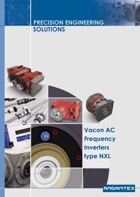
SOLUTIONS Vacon AC Frequency Inverters type NXL - Andantex UK
SOLUTIONS Vacon AC Frequency Inverters type NXL - Andantex UK
SOLUTIONS Vacon AC Frequency Inverters type NXL - Andantex UK

Create successful ePaper yourself
Turn your PDF publications into a flip-book with our unique Google optimized e-Paper software.
mf4-mf6 product rangeMains voltage 380—500 V, 50/60 Hz, 3~, enclosure class IP21/IP54, EMC level HLoadabilityMotor shaft powerLow High 400 V supply<strong>AC</strong> drive <strong>type</strong> *RatedcontinuouscurrentI L (A)10%overloadcurrent(A)RatedcontinuouscurrentI H (A)50%overloadcurrent(A)Maximum 10%current I S overload40°CP (kW)50%overload50°CP (kW)Frame size<strong>NXL</strong><strong>NXL</strong><strong>NXL</strong><strong>NXL</strong><strong>NXL</strong><strong>NXL</strong>0003000400050007000900125 C 2 H 15 C 2 H 15 C 2 H 15 C 2 H 15 C 2 H 15 C 2 H 13.34.35.67.69123.64.76.28.49.913.22.23.34.35.67.693.35.06.58.411.413.54.46.28.610.814181.11.52.2345.50.751.11.52.234MF4MF4MF4MF4MF4MF4<strong>NXL</strong><strong>NXL</strong><strong>NXL</strong>0016002300315 C 2 H 15 C 2 H 15 C 2 H 116233117.625.33412162318.024.0352432467.511155,57,511MF5MF5MF5<strong>NXL</strong><strong>NXL</strong><strong>NXL</strong>0038004600615 C 2 H 15 C 2 H 15 C 2 H 138466142516731384647576962769218.522301518.522MF6MF6MF6* Type code of the IP21 unit. The <strong>type</strong> code of the IP54 unit: replace ‘2’ with ‘5’; for example, <strong>NXL</strong> 0003 5C5H1For all <strong>Vacon</strong> <strong>NXL</strong> drives, overloadability is defined as follows:High: 1.5 x I H (1 min/10 min) at 50°C; Low: 1.1 x I L (1 min/10 min) at 40°C; I S for 2 seconds every 20 seconds.vacon nxl mf4–mf6 <strong>type</strong> designation code<strong>NXL</strong> 0007 5 C 2 H 1 SSS 00 AIFactory installed I/O expander boards and fieldbus boards (slot E)00 = no boardAI = I/O extension board (3xDI, 1xRO, 1xTherm)AA = I/O extension board (3xDI, 1xRO, 1xDO)C3 = Profibus DP- More boards, see page 6Factory installed fieldbus boards (slot D)00 = no boardC3 = Profibus DP- More boards, see page 6Hardware modifications (power unit, special modifications, board varnishing)SSS = standardSSV = varnished boardsSTS = flange mountingBrake chopper option1 = internal brake chopper (standard)Emission levelH = fulfills the standard EN 61800-3 (2004), category C2C = fulfills the standard EN 61800-3 (2004), category C1T = Low earth-current solution for IT networks (can be modified from H level units)Enclosure classification2 = IP215 = IP54Control keypadC = 7-segment LCD keypadB = no keypadNominal mains voltage5 = 380…500 V <strong>AC</strong> (3-phase)Nominal current (Low overload)e.g. 0007 = 7 AmpsProduct range<strong>Vacon</strong> <strong>NXL</strong>4
compact yet so powerfulThe <strong>Vacon</strong> <strong>NXL</strong> range also offers compact, cabinet-mounted units for lower motor powers.Frames MF2 and MF3 are suitable for both 208–230 V and 380–500 V supply voltages for powersup to 2.2 kW. The compact size and flexible installation options make the <strong>Vacon</strong> <strong>NXL</strong> suitable forinstallations where space is at a premium. The standard control I/O can be extended with oneI/O expander board or one fieldbus board.Features• Small size• Flexible installation (back or side, screw or DIN rail)• Easy to install and use• Low noise• Large amount of control possibilities (via I/Os,fieldbuses or display panel)• Large amount of features (e.g. fully programmableI/O, auto-identification, PID controller, flying start)• High performance• RFI filters and <strong>AC</strong> chokes available as optionsMains voltage 380—500 V, 50/60 Hz, 3~, enclosure class IP20, EMC level NLoadabilityMotor shaft powerLow High 400 V supply<strong>AC</strong> drive <strong>type</strong>RatedcontinuouscurrentI L (A)10%overloadcurrent(A)RatedcontinuouscurrentI H (A)50%overloadcurrent(A)Maximum 10%current I S overload40°CP (kW)50%overload50°CP (kW)Frame size anddimensions(W x H x D)<strong>NXL</strong> 0001 5 C 1 N 0 1.9 2.1 1.3 2.0 2.6 0.55 0.37 MF2 / 60 x 130 x 150<strong>NXL</strong> 0002 5 C 1 N 0 2.4 2.6 1.9 2.9 3.8 0.75 0.55 MF2 / 60 x 130 x 150<strong>NXL</strong> 0003 5 C 1 N 1 3.3 3.6 2.4 3.6 4.8 1.1 0.75 MF3 / 84 x 184 x 172<strong>NXL</strong> 0004 5 C 1 N 1 4.3 4.7 3.3 5.0 6.6 1.5 1.1 MF3 / 84 x 184 x 172<strong>NXL</strong> 0005 5 C 1 N 1 5.4 5.9 4.3 6.5 8.6 2.2 1.5 MF3 / 84 x 220 x 172Mains voltage 208—240 V, 50/60 Hz, 1/3~ (3~ motor), enclosure class IP20, EMC level NLoadabilityMotor shaft powerLow High 230 V supply<strong>AC</strong> drive <strong>type</strong>RatedcontinuouscurrentI L (A)10%overloadcurrent(A)RatedcontinuouscurrentI H (A)50%overloadcurrent(A)Maximum 10%current I S overload40°CP (kW)50%overload50°CP (kW)Frame size anddimensions(W x H x D)<strong>NXL</strong> 0002 2 C 1 N 0* 2.4 2.6 1.7 2.6 3.4 0.37 0.25 MF2 / 60 x 130 x 150<strong>NXL</strong> 0003 2 C 1 N 1 3.7 4.1 2.8 4.2 5.6 0.75 0.55 MF3 / 84 x 184 x 172<strong>NXL</strong> 0004 2 C 1 N 1 4.8 5.3 3.7 5.6 7.4 1.1 0.75 MF3 / 84 x 184 x 172<strong>NXL</strong> 0006 2 C 1 N 1 6.6 7.2 4.8 7.2 9.6 1.5 1.1 MF3 / 84 x 220 x 172* suitable only for single-phase supply voltage (the rest suitable for both single-phase and three-phase supply voltages)5
vacon nxl control unitI/O expander boards,fieldbus boardsThe standard I/O of the <strong>Vacon</strong> <strong>NXL</strong> has been optimized for typicalcontrol requirements. In addition to digital and analog inputsand outputs, RS485 is included as standard. All inputs andoutputs of the standard I/O and option boards are freely programmable.Both Analog Inputs can be programmed for 0...10 Vor 0(4)...20 mA signals. Analog Input can also be programmedas Digital Input.Standard I/OThe standard I/O can easily and cost-effectively be extendedwith OPT-AA or OPT-AI boards, if necessary. The OPT-AA is themost effective way to add one more Relay Output, and the OPT-AI is normally used when galvanically isolated motor thermistorconnection is needed. These boards are installed in optionboard slot E.It is also possible to control the <strong>Vacon</strong> <strong>NXL</strong> with various kinds offieldbuses with OPT-C-<strong>type</strong> boards (see the table below). TheI/O extension and fieldbus boards are the same for all <strong>Vacon</strong> NXproducts. The fieldbus boards can be installed in slot D or E.There are a large number of OPT-B-<strong>type</strong> option boards available.The most typical boards are included in the table below. Itis possible, for instance, to add three more output relays withOPT-B5, if necessary. The OPT-B-<strong>type</strong> boards are typically installedin slot E.vacon nxl option boardsCard <strong>type</strong>code Slot I/O signalD E DI DO AImAisol.AOmAisol.RONONCRONOTherm +24EXT+24VNOTEBasic I/O cards (OPT-A)OPT-AA 3 1 1OPT-AI 3 1 1I/O expander cards (OPT-B), typicalOPT-B2 1 1 1OPT-B4 1 2 1 analog signals galvanically isolated separatelyOPT-B5 3Fieldbus cards (OPT-C)OPT-C2 RS-485 (Multiprotocol) N2 (Modbus as standard)OPT-C3OPT-C4OPT-C5OPT-C6OPT-C7Profibus DPLonWorksProfibus DP (D9 <strong>type</strong> connector)CANopen (slave)DeviceNetOPT-C8 RS-485 (Multiprotocol, D9 <strong>type</strong> connector) N2 (Modbus as standard)OPT-CIOPT-CJModbus/TCP (Ethernet)B<strong>AC</strong>netNOTES: Allowed slots for the board are marked in blue. Allowed option board combinations are as follows:no boards, 1xOPT-Ax, 1xOPT-Bx, 1xOPT-Cx, or 1xOPT-Ax and 1xOPT-Cx.6
vacon nxl control i/oStandard I/OOPT-AA (typical option)TerminalSignal, default settingsTerminalSignal, default settings1...10 kmA1 +10V Reference voltage2 AI1+ Analog input, 0–10 V (0/4–20 mA)3 AI1- AI common4 AI2+ Analog input, 0/4–20 mA (0–10 V)5 AI2- AI common6 +24V 24V auxiliary voltage7 GND I/O ground8 DIN1 Start forward9 DIN2 Start reverse10 DIN3 Preset speed 111 GND I/O ground18 AO1+ Analog output, output frequency19 AO1- AO commonA RS485 Serial bus (Modbus RTU)B RS485 Serial bus30 +24V External control voltage supply21 RO1 Relay output 1, FAULT22 RO123 RO1All inputs and outputs of the standard I/O and option boards arefreely programmable.1 +24V 24 V auxiliary voltage2 GND I/O ground3 DIN1 Preset speed 24 DIN2 Fault reset5 DIN3 Disable PID6 DO1 Digital output, Ready24 RO1 Relay output 1, RUN25 RO126 RO1OPT-AI (typical option)Terminal Signal, default settings12 +24V 24 V auxiliary voltage13 GND I/O ground14 DIN1 Preset speed 215 DIN2 Fault reset16 DIN3 Disable PID25 RO1 Relay output 1, RUN26 RO128 TI1+ Thermistor input29 TI1- (galvanically isolated)other typical optionsOPTION ORDER TYPECODE SUITABILITY NOTEIP54 enclosure Factory option MF4-MF6 Replace ‘2’ by ‘5’ in the <strong>type</strong> code, e.g. <strong>NXL</strong>00315C5H1 (SSS...)IP5-FR_ MF4-MF6 IP54 kit, e.g. IP5-FR4Through-hole mounting Factory option MF4-MF6 E.g. <strong>NXL</strong>00315CTH1STS..., IP54 back, IP21 front, kits availableExternal brake resistors BRR-0022-LD-5 00035-00225 LD = Light Duty: 5 sec nominal torque braking fromBRR-0031-LD-5 00315nominal speed decreasing linearily to zero, once per 120 sec.HD = Heavy Duty: 3 sec nominal torque braking atBRR-0045-LD-5 00385-00465 nominal speed + 7 sec nominal torque braking from nominalBRR-0061-LD-5 00615speed decreasing linearily to zero, once per 120 sec.Replace LD by HD in the <strong>type</strong> code, e.g. BRR-0031-HD-5The brake resistor manual is available for more precise selectionPanel door installation setsDRA-02LDRA-04LAllDoor installation set with a 2-m RS232C cableDoor installation set with a 4-m RS232C cablePC adapter PAN-RS All Adapter PAN-RS and a RS232C cable are required for PC connectionRS232C cablesRS232C-2MRS232C-4MAll2-meter-long RS232C cable for PC connection4-meter-long RS232C cable for PC connectionVarnished circuit boards Factory option MF4-MF6 Replace the ‘S’ by ‘V’, e.g. <strong>NXL</strong>00315C5H1SSV...C-level RFI filters Factory option MF4-MF6 Replace ‘H’ by ‘C’ in the <strong>type</strong>code, e.g. <strong>NXL</strong>00315C2C1 (SSS...)OPTIONS FOR COMP<strong>AC</strong>T UNITS (MF2-MF3)RFI filters RFI-0012-2-1 00022-00062 RFI filter for 208-230 V units, H level, 1~ supplyRFI-0013-2-1 00022-00062 RFI filter for 208-230 V units, H level, 1~ supply, footprint installationRFI-0008-5-1 00015-00055 RFI filter for 380-500 V units, H level, footprint installationDIN rail installation Factory option MF2-MF3 Replace ‘S’ by ‘D’ in the <strong>type</strong>code, e.g. <strong>NXL</strong> 00025C1HO SDS7
first-class usabilityThe basic settings can be programmed by simply launching the <strong>Vacon</strong> <strong>NXL</strong> start-up wizard. Onlyfour steps are required, and the drive is ready to run.START-UP WIZARD=Push the buttonSTART MODE rpm n I n (A)+rpmA++-++-ENTERreset-ENTERreset-ENTERreset-ENTERreset1 Push 5 seconds 2 Select the 3 Accept4 Tune 5 Accept6 Tune Acceptto activate (inmode. Seen(rpm)7I(A)stop mode)table below!P2.1.1Min. Freq (Hz)P2.1..2 Max.Freq (Hz)P2.1.3 Acc time (s)P2.1.4 Dec time (s)P2.1.5 Current limit(A)P2.1.6 Motor Un (V)P2.1.7 Motor fn(Hz)P2.1.11Start funct.P2.1.12 Stop funct.P2.1.13 U/f optimizationP2.1.14 I/0 refP2.1.21 Auto restartP3.1 Control placeMStandardFanPump0Hz20Hz20Hz0HzHighperformance50Hz50Hz50Hz50Hz3s20s5s1s3s20s5s1sI *1,5 400HVI *1,1 400LVI *1,1 400LVI *1,8 400HV50Hz50Hz50Hz50Hz0= 0=Ramp Coasting0= 0=Ramp Coasting0=Ramp1=Ramp0= 0=Ramp Coasting0=Notused0=Notused0=Notused1=automatictorqueboost0=Ai10-10V0=Ai10-10V0=Ai10-10V0=Ai10-10V0=Notused0=Notused0=Notused0=NotusedI/OI/OI/OI/OFor example: These settings are made automaticallyif the fan mode is selected.The instructions to install, connect and program the <strong>Vacon</strong><strong>NXL</strong> are included in the credit-card size Quick Guide attachedto each unit.8
multi-control applicationThe standard Multi-Control Application software of the <strong>Vacon</strong> <strong>NXL</strong> is extremely flexible and easyto use. All inputs and outputs are programmable, and there is a full set of features and possibilitiesfor system or process control and protections.The default settings are very close to optimum, and thedrive operates accurately enough without any programming.It still is recommended to check and fine-tune the motornominal values to optimize the performance and motorprotection. Programming can be made simply by using thestart-up wizard feature of the display panel, programmingparameter by parameter with display panel, or programmingby the NCDrive tool. The instructions, if required, canbe found in the credit-card-size Quick Guide.The <strong>Vacon</strong> PC tools are available for downloading from the<strong>Vacon</strong> website at http://www.vacon.com. These include:• <strong>Vacon</strong> NCDrive for parameter setting, copying, storing,printing, monitoring and controlling• <strong>Vacon</strong> NCLoad for software updating and uploadingspecial software to the drive• <strong>Vacon</strong> NC1131-3 Engineering is available for making tailormadesoftware. (A license key and training required)There are many parameters and features which can be utilized,if necessary. For example:The following software applications are available for specialrequirements:• PID controller• Pump and fan control for a maximum of 4 parallel motors• Flying start• Auto-tuning• Programming of all control inputs and outputs• Output relay delaysIn addition to the standard MultiControl Application software,some special application software is also available. Itis even possible to make totally customer-specific softwarewith the NC1131-3 Engineering tool, and remove the PLC byintegrating the logic to the <strong>NXL</strong> software.• Brake control• Lift• Multi-motor• Sliding door• Local/remote• Fire mode• Multi-purposeExpander board menuSystem menuFault history menu+- ENTERresetActive faults menuKeypad control menuParameter menuNavigation andselection keysMonitoring menuNavigating the menu structure (e.g. special parameters,monitoring signals)Activating the start-up wizard9
emc and installation environment1ST ENVIRONMENT3212452ND ENVIRONMENTThe product family standard EN61800-3 sets limits for bothemissions and immunity of radio frequency disturbances. Theenvironment has been divided into the 1st and 2nd environments,which, in practice, means public and industrial networks.Radio <strong>Frequency</strong> Interference (RFI) filters are typically requiredto meet the EN61800-3 standard. These filters are integrated inthe <strong>Vacon</strong> <strong>NXL</strong> MF4-MF6 as standard.The <strong>Vacon</strong> <strong>NXL</strong> fulfills all the requirements of the 1st and 2ndenvironments (H level: EN61800-3 (2004), category C2). No additionalRFI filters or cabinets are required for frames MF4-MF6.The <strong>Vacon</strong> <strong>NXL</strong> MF4-MF6 units are also available with extremelylow-emission integrated EMC filters (C level: EN61800-3(2004), category C1; EN55011, class B). These filters are sometimesrequired in very sensitive locations such as hospitals.EMC Selection Table, restricted distribution1 2 3 4 5<strong>Vacon</strong> <strong>NXL</strong> EMC Hospital Residential Area Commercial Light Industry Area Heavy Industry MarineCOH R R R O OL R RT R (IT Network) R (IT Network)R = Required ; O = Optional10
technical dataMainsconnectionMotorconnectionControlcharacteristicsInput voltage U in 380…500 V, –10%…+10%, 208...240 V, -10%...+10%Input frequency45…66 HzConnection to mainsOnce per minute or less (normal case)Output voltage0...U inContinuous output currentHigh overloadability: I H , ambient temperature max. +50°CLow overloadability: I L , ambient temperature max. +40°COverloadabilityHigh: 1.5 x I H (1 min/10 min), Low: 1.1 x I L (1 min/10 min)Max. starting currentI s for 2 s every 20 sOutput frequency0…320 Hz<strong>Frequency</strong> resolution0.01 HzControl method<strong>Frequency</strong> control U/f; Open Loop Vector Control (speed, torque)Switching frequency1…16 kHz; Factory default 6 kHzField weakening point8…320 HzAcceleration time0…3000 sDeceleration time0…3000 sBrakingDC brake: 30% * T N (without brake resistor), flux brakingAmbient conditions Ambient operating temperature –10°C (no frost)…+50°C: I H–10°C (no frost)…+40°C: I LStorage temperature–40°C…+70°CRelative humidity0 to 95% RH, non-condensing, non-corrosive, no dripping waterAir quality:- chemical vapours- mechanical particlesAltitudeVibrationEN50178/EN60068-2-6ShockEN50178, EN60068-2-27Enclosure classIEC 721-3-3, unit in operation, class 3C2IEC 721-3-3, unit in operation, class 3S2100% load capacity (no derating) up to 1000 m1% derating for each 100 m above 1000 m; max. 3000 m5...150 HzDisplacement amplitude 1 mm (peak) at 3…15.8 HzMax acceleration amplitude 1 G at 15.8…150 HzUPS Drop Test (for applicable UPS weights)Storage and shipping: max 15 G, 11 ms (in package)MF4-MF6: IP21 and IP54; MF2-MF3: IP20EMC Immunity Fulfills all EMC immunity requirementsEmissionsMF4-MF6:EMC level H: EN61800-3 (2004), category C2; EN61000-6-4, EN50081-2; EN55011 class AEMC level C: EN61800-3 (2004), category C1; EN61000-6-3, EN50081-1,-2; EN55011 class BEMC level T: Low earth-current solution suitable for IT networks (can be modified from H-level units)MF2-MF3:EMC level N: EN61800-3 (2004), category C4EMC level H w/ RFI filter: EN61800-3 (2004), category C2; EN61000-6-4, EN50081-2; EN55011 class A.SafetyControlconnections(values in bracketsvalid for OPT-AA orOPT-AI)ProtectionsEN 50178 (1997), EN 60204-1 (1996), EN 60950 (2000, 3rd edition) (as relevant),IEC 61800-5, CE, UL, CUL, FI, GOST R; (see unit nameplate for more detailed approvals)Analogue input voltage 0…+10 V, R i = 200 k, resolution 0.1%, accuracy ±1%Analogue input current 0(4)…20 mA, R i = 250 differential, resolution 0.1%, accuracy ±1%Digital inputs3 (6), 18…30 VDCAuxiliary voltage+24 V, ±15 %, max. 100 mAOutput reference voltage +10 V, +3%, max. load 10 mAAnalogue output 0(4)…20 mA; R L max. 500 , resolution 10 bit, accuracy ±2%Relay outputs1 (2) programmable relay output(s)Switching capacity: 24 VDC/8 A, 250 V<strong>AC</strong>/8 A, 125 VDC/0.4 A. Min. switching load: 5 V/10 mARS-485Serial bus (Modbus RTU)Thermistor inputGalvanically isolated, R trip = 4.7 k (OPT-AI)Overvoltage, undervoltage, earth fault, motor phase supervision, overcurrent, unit overtemperature,motor overload, motor stall, motor underload, short-circuit of +24 V and +10 V reference voltages11
www.andantex.co.ukUnited-KingdomANDANTEX LtdRowley DriveCoventry CV3 4LSTel. +44 24 7630 7722Fx +44 24 7630 4499Web : www.andantex.co.ukE-mail : sales@andantex.co.ukYour local agent