EP Pergola Installation Instructions - Intex Millwork Solutions
EP Pergola Installation Instructions - Intex Millwork Solutions
EP Pergola Installation Instructions - Intex Millwork Solutions
- No tags were found...

Create successful ePaper yourself
Turn your PDF publications into a flip-book with our unique Google optimized e-Paper software.
<strong>Intex</strong> Engineered <strong>Pergola</strong> System <strong>Installation</strong> <strong>Instructions</strong>NOTE: See Appendix for Foundation Requirements<strong>Pergola</strong> <strong>Installation</strong>, Freestanding (If pergola will be attached-to-structure, skip to page 3)1. Carrying Beam <strong>Installation</strong>, 6 X 6 or 8 x 8 TimberPosta. Measure the center to center distance of thetimber posts which will support the CarryingBeams. Mark this distance on the bottom of theCarrying Beam so the ends of the beam willextend an equal distance beyond the supportingposts.b. Center a Perpost Cap and a Beam-to-PostBracket at the locations determined in Step 1a.c. Drill 1/8” pilot holes at the locations shown inFigure 1a. The quantity and location of theholes is determined by the width of the CarryingBeam.d. Mount the Perpost Caps and Beam to PostBrackets to the Carrying Beam with theprescribed number of 1/4" X 2-1/2” long hexhead self tapping stainless steel screws.e. On the centerline of the bottom of the beam, measure 2 inches from the inside of the edges of the PerpostCaps and mark the locations.f. Drill a 1.00” Diameter hole through the PVC at the two locations created in Step 1e. Be careful not to drillthrough the aluminum reinforcement. Insert Drain Plugs provided at these locations.g. Repeat with the other Carrying Beam(s).Figure 1ah. Place the completed Carrying Beam assembly on top of thecorresponding timber posts.i. Drill 1/8” pilot holes through the five holes on each side ofthe Beam to Post Bracket.j. Mount the Carrying Beam assembly to the timber post withthe 1/4" X 2-1/2” long hex head stainless steel screws asshown.k. Repeat these steps and mount the other end of the CarryingBeam(s).V2-1-13Page 1
2. Rafter <strong>Installation</strong>a. Once both Carrying Beans are installed, set one Rafter in place and center it so that each tail end extendsequally past the Carrying Beams.b. Mark the underside of the Rafter at the inside and outside of the Carrying Beam at each end. These marksmay be visible after Rafters are installed, so use light pencil or other removable marking.c. Remove Rafter and turn upside down.d. Align all remaining Rafters next to the marked Rafter, and transfer lines across to all. This step assumes theCarrying Beams are parallel. If this is not the case, please modify accordingly.e. Center a Rafter bracket between the marked lines with the center holes countersink up and the bracketextending out past the sides of the Rafter. The bracket used as well as the location and quantity of mountingholes is determined by the width of the Rafter. See Figure 2a. Note that the scribed lines on the oppositeside of the bracket are used to center the bracket across the Rafter.f. With the brackets centered between the marked lines and across the Rafter, drill 1/8” pilot holes through themounting holes into the Rafter.Figure 2a4 1 25 1 21 3 41 3 4For 2-1/2" WideRafter to Any SizeBeam AttachmentFor 3-1/2" Wide 'Ice Load'Rafter to Any Size BeamAttachmentg. Attach the bracket to the Rafter using the 1/4"X 2” long flat head self tapping stainless steelscrews.h. Repeat steps e-g for all Rafter brackets.i. On the bottom of each Rafter, approximately1/2” from the inside edge of the each bracket,drill a 1/8” drain hole through the PVC. Becareful not to drill through the aluminumreinforcement.j. Measure center to center of the timber postsand divide this measurement by the number ofrafter spaces (you should have one moreRafter than the number of spaces). This is the centerline spacing to set each Rafter.k. Mark both Carrying Beams with center linemeasurements for all the Rafters to confirm spacingbefore installation.l. Place Rafters on Carrying Beams and center onmarks.m. Drill 1/8” pilot holes and attach Rafter brackets toCarrying Beams using 1/4" X 2” long flat head selftapping stainless steel screws.V2-1-13Page 2
3. Purlin or Lath <strong>Installation</strong>a. Once all Rafters are installed, measurethe distance between the outside edgesof the outer two Rafters.b. Determine the amount of overhangdesired for your application. TypicalPurlin overhang would be 8” to 12” oneach end, and Lath overhang would be6” to 8”. Add twice the overhang desiredto the measured distance. This is theoverall Purlin or Lath length.c. Once all Purlin or Lath is sized, set one inplace and center across Rafters withequal overhang at each end. Mark theunder the side of the Purlin or Lath at theoutside of the outer Rafter each end.d. Remove Purlin or Lath and turn upsidedown.e. Align all remaining Purlin or Lath next tothe marked one, and transfer lines across to all. These marks may be visible after Purlin or Lath is installed, souse light pencil or other removable marking. This step assumes the Carrying Beams are parallel. If this is notthe case, please modify accordingly.f. Measure center to center of the Carrying Beams and divide this measurement by the number of Purlin or Lathspaces (you should have one more Purlin or Lath than the number of spaces). This is the center line spacingto set each Purlin or Lath.g. Mark both end rafters with center line measurements for all the Purlin or Lath to confirm spacing beforeinstallation.h. Place Purlin or Lath across Rafters and center to marks.i. Purlin or Lath should be secured with a screw into the Rafter at each intersection along the two outsideRafters, and then every other Rafter for the remainder of the intersections. Insure that Purlin or Lath arestraight along their entire length before securing with screws: If using Purlin, drill 1/8” pilot holes through the top and bottom of the Purlin into the Rafter and secure with4-1/2” stainless or coated screws. If using Lath, secure with stainless #10-32 x 1-1/2” screws<strong>Pergola</strong> <strong>Installation</strong>, Attached-to-Structure1. Carrying Beam <strong>Installation</strong>a. Reference step 1a to 1k under “<strong>Pergola</strong> <strong>Installation</strong>, Freestanding”. Follow these steps to install the singleCarrying Beam used for this application.2. Ledger Board/Cover <strong>Installation</strong> where Rafter ends rest on top of Ledger Board Cover(<strong>Intex</strong> recommends that a pressure treated double 2 x 10 be used as the structural ledger board)a. Transfer height from top of Carrying Beam to wall, measure down 5/8” and snap line.b. Align the top of the structural ledger board with the snap line and attach using appropriate fastening methods.Counter sink screws or bolts to preclude interference with Ledger Board Cover.c. Fit Ledger Board Cover over structural ledger board and attach using stainless steel finish nails.3. Ledger Board/Cover <strong>Installation</strong> where Rafter ends mount to face of Ledger Board Cover(<strong>Intex</strong> recommends that a pressure treated double 2 x 10 be used as the structural ledger board)a. Follow these steps if you want the bottom of the Rafters to be flush with the bottom of the Ledger BoardCover. Adjust the snap line up or down to achieve your desired result.b. Transfer height from top of Carrying Beam to wall, measure up 5/8” and snap line.c. Align the bottom of the structural ledger board with the snap line and attach using appropriate fasteningmethods. Counter sink screws or bolts to preclude interference with Ledger Board Cover.d. Fit Ledger Board Cover over structural ledger board and attach using stainless steel finish nails. The insidebottom edge of the Ledger Board Cover should fit tight to the bottom of the structural ledger board.V2-1-13Page 3
4. Rafter <strong>Installation</strong> where Rafter ends rest on top ofLedger Board Covera. Once the Carrying Beam and the Ledger BoardCover are installed, place one Rafter with the flatbutt end on top of the Ledger Board Cover, tightagainst the wall.b. Mark the underside of the Rafter at the inside andoutside of the Carrying Beam and at the outside ofthe Ledger Board Cover. These marks may bevisible after Rafters are installed, so use lightpencil or other removable marking.c. Remove Rafter and turn upside down.d. Align all remaining Rafters next to the markedRafter, and transfer lines across to all.e. Center a Rafter bracket between the marked lineswith the center holes countersink up and thebracket extending out past the sides of the Rafter. For the butt end, center the bracket between the markedline and the end of the Rafter. The bracket used as well as the location and quantity of mounting holes isdetermined by the width of the Rafter. See Figure 2a. Note that the scribed lines on the opposite side of thebracket are used to center the bracket across the Rafter.f. With the brackets centered between the marked lines and across the Rafter, drill 1/8” pilot holes through themounting holes into the Rafter.g. Attach the bracket to the Rafter using the 1/4" X 2” long flat head self tapping stainless steel screws.h. On the bottom of each Rafter, approximately 1/2” from the inside edge of each bracket, drill a 3/8” drain holethrough the PVC. Be careful not to drill through the aluminum reinforcement Repeat steps e-h for all Rafterbrackets.i. Measure center to center of the timber posts and divide this measurement by the number of rafter spaces(you should have one more Rafter than the number of spaces). This is the center line spacing to set eachRafter.j. Mark the Carrying Beam with center line measurements for all the Rafters to confirm spacing beforeinstallation. Transfer these spacing marks to the top of the Ledger Board Cover, insuring that alignment ofrafters will be perpendicular to wall.k. Place Rafters across Ledger Board Cover and Carrying Beam and center to marksl. Drill 1/8” pilot holes and attach Rafter brackets to Carrying Beam and Ledger Board Cover using 1/4" X 2”long flat head self tapping stainless steel screws.5. Rafter <strong>Installation</strong> where Rafter ends mount to faceof Ledger Board Covera. Once the Carrying Beam and the LedgerBoard Cover are installed, place one Rafterwith the flat butt end tight against the face ofthe Ledger Board Cover.b. Mark the underside of the Rafter at the insideand outside of the Carrying Beam. Thesemarks may be visible after Rafters areinstalled, so use light pencil or otherremovable marking.c. Remove Rafter and turn upside down.d. Align all remaining Rafters next to the markedRafter, and transfer lines across to all.e. Center a Rafter bracket between the markedlines with the center holes countersink up andthe bracket extending out past the sides of theRafter. The bracket used as well as thelocation and quantity of mounting holes isdetermined by the width of the Rafter. SeeFigure 2a. Note that the scribed lines on theopposite side of the bracket are used to centerthe bracket across the Rafter.V2-1-13Page 4
f. With brackets centered between the marked lines and across the Rafter, drill 1/8” pilot holes through themounting holes into Rafter.g. Attach the bracket to the Rafter using the 1/4" X 2” long flat head self tapping stainless steel screwsh. On the bottom of each Rafter, approximately 1/2” from the inside edge of the bracket, drill a 3/8” drain holethrough the PVC. Be careful not to drill through the aluminum reinforcement.i. Repeat steps e-h for each Rafter.j. Measure center to center of the timber posts and divide this measurement by the number of rafter spaces(you should have one more Rafter than the number of spaces). This is the center line spacing to set eachRafter.k. Mark the Carrying Beam with center line measurements for all the Rafters to confirm spacing beforeinstallation. Transfer these spacing marks to the vertical face of the Ledger Board Cover, insuring thatalignment of rafters will be perpendicular to wall.l. Determine the location of the top of the Rafters and measure down 3/4“. Mark this horizontal position acrossthe face of the Ledger Board Cover. Attach a ledger board bracket centered on each mark on the LedgerBoard Cover, with the top of the bracket aligned with the 3/4“ position.m. Drill 1/8” pilot holes and secure the ledger board bracket to the Ledger Board Cover with (2) 1/4" X 3” longhex head stainless steel screws.n. Place the Rafter on top of the Carrying Beam and over the ledger board bracket so the aluminumreinforcement rests on top of the bracket and Rafter is centered on each mark.o. Drill three 1/8” pilot holes down through the Rafter above the ledger board bracket. Drill through the PVC,aluminum reinforcement and the bracket. Attach the end of the Rafter to the ledger board bracket with three1/4" X 2” long flat head self-tapping stainless steel screws.p. Insure alignment/spacing of Rafter, across Carrying Beam and center to marksq. Drill 1/8” pilot holes and attach Rafter brackets to the Carrying Beam using 1/4" X 2” long flat head selftappingstainless steel screwsr. Repeat step m thru q until all of the Rafters are installed.6. Purlin or Lath <strong>Installation</strong>a. Once all Rafters are installed, measure the distance between the outside edges of the outer two Rafters.b. Determine the amount of overhang desired for your application. Typical Purlin overhang would be 8” to 12” oneach end, and Lath overhang would be 6” to 8”. Add twice the overhang desired to the measured distance.This is the overall Purlin or Lath length.c. The overall length of the supplied Purlin or Lath material may be less than the distance between the outsideedges of the two Rafters. If so, splice two pieces together accordingly to achieve the desired overall length.The location of the splice is critical and should be located above Rafter for support.d. Once all Purlin or Lath is sized, set one in place and center across rafters with equal overhang at each end.Mark the under the side of the Purlin or Lath at the outside of the outer Rafter each end.e. Remove Purlin or Lath and turn upside down.f. Align all remaining Purlin or Lath next to the marked one, and transfer lines across to all. These marks maybe visible after Purlin or Lath is installed, so use light pencil or other removable marking.g. Measure from the butt end of the Rafter to the center of the Carrying Beam and divide this measurement bythe number of Purlin or Lath spaces (you should have one more Purlin or Lath than the number of spaces).This is the center line spacing to set each Purlin or Lath.h. Mark both end rafters with center line measurements for all the Purlin or Lath to confirm spacing beforeinstallation.i. Place Purlin or Lath across Rafters and center on marks.j. Purlin or Lath should be secured with a screw into the Rafter at each intersection along the two outsideRafters, and then every other Rafter for the remainder of the intersections. Insure that Purlin or Lath arestraight along their entire length before securing with screws: If using Purlin, drill 1/8” pilot holes through the top and bottom of the Purlin into the Rafter and secure with4-1/2” stainless or coated screws. If using Lath, secure with stainless #10-32 x 1-1/2” screwsNOTE: For any application in these instructions that call for /epoxy INTEX recommends TRIMBONDER 2 partepoxy or BOND AND FILL 2 part epoxy.V2-1-13Page 5
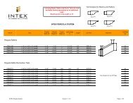
Perpost CapCarrying Beam BracketRafter Bracket for use with2-1/2" X 9-3/16" RafterRafter Bracket for use with3-1/2" X 9-3/16" RafterFor use with 1/4" X 2" Flat HeadSelf Tapping Stainless Steel ScrewsPlease note Rafter Brackets do not include screws.The required screw is sold in bags of 150which are sold seperately from the brackets.Bracket Includes (12)1/4" X 2-1/2" Hex HeadSelf Tapping Stainless Steel ScrewsBracket Includes (2)1/4" X 3" Hex HeadStainless Steel Screwsand (10) 1/4" X 2-1/2" Hex HeadStainless Steel ScrewsLedger Board BracketV2-1-13Page 6
APPENDIX PERGOLA SUPPORT POSTSFoundation Tables6x6 Wood PostMax Beam Span Max Rafter Span Concrete Pier Size14' 20' 18" diameter x 5' deep14'‐6" 16' 18" diameter x 5' deep8x8 Wood PostMax Beam Span Max Rafter Span Concrete Pier Size25' 25' 30" diameter x 5' deep22' 18' 30" diameter x 5' deep20' 18' 30" diameter x 5' deep18' 18' 24" diameter x 4'‐9" deepNote: These foundations will meet International Building Codes for 120 mph windand an open structure. For more details and foundation requirements for a roofedstructure, or to download our complete engineering specifications, please go towww.intexmillwork.comWOODEN POST TO CONCRETE PIER EMBEDMENT FORUPLIFT. FOR USE WITH 6X6 OR 8X8 WOODEN POSTS IN18", 24" OR 30" DIAMETER PIERSV2-1-13Page 7