SQ-SI Datasheet - SignalQuest
SQ-SI Datasheet - SignalQuest
SQ-SI Datasheet - SignalQuest

You also want an ePaper? Increase the reach of your titles
YUMPU automatically turns print PDFs into web optimized ePapers that Google loves.
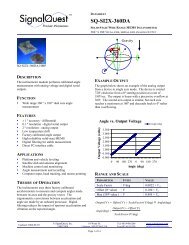
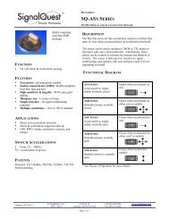
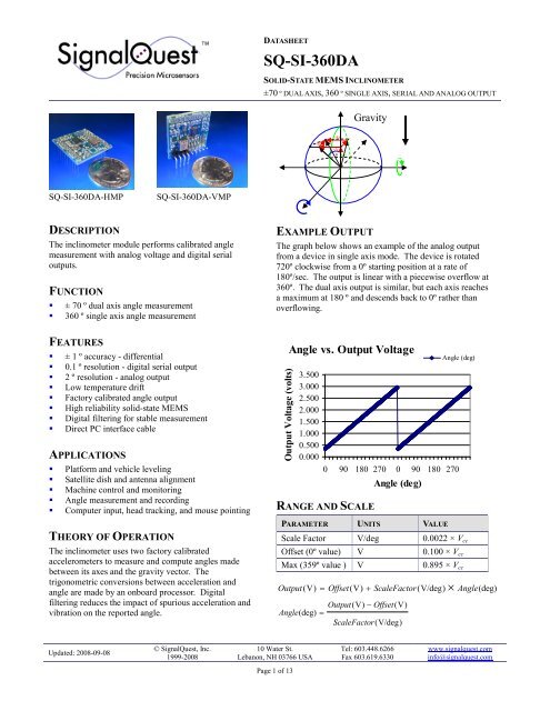
DATASHEET<strong>SQ</strong>-<strong>SI</strong>-360DASOLID-STATE MEMS INCLINOMETER±70 º DUAL AXIS, 360 º <strong>SI</strong>NGLE AXIS, SERIAL AND ANALOG OUTPUTGravity-Az-Ax+Aθφ<strong>SQ</strong>-<strong>SI</strong>-360DA-HMP<strong>SQ</strong>-<strong>SI</strong>-360DA-VMPDESCRIPTIONThe inclinometer module performs calibrated anglemeasurement with analog voltage and digital serialoutputs.FUNCTION± 70 º dual axis angle measurement360 º single axis angle measurementFEATURES± 1 º accuracy - differential0.1 º resolution - digital serial output2 º resolution - analog outputLow temperature driftFactory calibrated angle outputHigh reliability solid-state MEMSDigital filtering for stable measurementDirect PC interface cableAPPLICATIONSPlatform and vehicle levelingSatellite dish and antenna alignmentMachine control and monitoringAngle measurement and recordingComputer input, head tracking, and mouse pointingTHEORY OF OPERATIONThe inclinometer uses two factory calibratedaccelerometers to measure and compute angles madebetween its axes and the gravity vector. Thetrigonometric conversions between acceleration andangle are made by an onboard processor. Digitalfiltering reduces the impact of spurious acceleration andvibration on the reported angle.EXAMPLE OUTPUTThe graph below shows an example of the analog outputfrom a device in single axis mode. The device is rotated720º clockwise from a 0º starting position at a rate of180º/sec. The output is linear with a piecewise overflow at360º. The dual axis output is similar, but each axis reachesa maximum at 180 º and descends back to 0º rather thanoverflowing.Output Voltage (volts)Angle vs. Output Voltage3.5003.0002.5002.0001.5001.0000.5000.0000 90 180 270 0 90 180 270RANGE AND SCALEAngle (deg)PARAMETER UNITS VALUEAngle (deg)Scale Factor V/deg 0.0022 × V ccOffset (0º value) V 0.100 × V ccMax (359º value ) V 0.895 × V ccOutput ( V) = Offset(V)+ ScaleFactor(V/deg)× Angle(deg)Output(V)− Offset(V)Angle(deg)=ScaleFactor(V/deg)Updated: 2008-09-08© <strong>SignalQuest</strong>, Inc.1999-200810 Water St.Lebanon, NH 03766 USATel: 603.448.6266Fax 603.619.6330www.signalquest.cominfo@signalquest.comPage 1 of 13
DATASHEET<strong>SQ</strong>-<strong>SI</strong>-360DASOLID-STATE MEMS INCLINOMETER±70 º DUAL AXIS, 360 º <strong>SI</strong>NGLE AXIS, SERIAL AND ANALOG OUTPUTTABLE OF CONTENTSAbsolute Maximum Ratings ........................................................................................................................................................3Electrical Characteristics .............................................................................................................................................................3Performance Parameters ..............................................................................................................................................................4Output Characteristics .................................................................................................................................................................4Pin Configuration.........................................................................................................................................................................5<strong>SQ</strong>-<strong>SI</strong>-360DA Series Package .....................................................................................................................................................6Dimensions ..................................................................................................................................................................................6Design, Layout, and Assembly Considerations ...........................................................................................................................7Serial Interface: HP and LP Versions...........................................................................................................................................7Reset Sources...............................................................................................................................................................................7Example Output: HP and LP Versions .........................................................................................................................................9Orientation .................................................................................................................................................................................10Ordering Guide ..........................................................................................................................................................................11Accessories ................................................................................................................................................................................11Limitations and Warnings ..........................................................................................................................................................13Testing .......................................................................................................................................................................................13System Integration Testing ........................................................................................................................................................13Updated: 2008-09-08© <strong>SignalQuest</strong>, Inc.1999-200810 Water St.Lebanon, NH 03766 USATel: 603.448.6266Fax 603.619.6330www.signalquest.cominfo@signalquest.comPage 2 of 13
DATASHEET<strong>SQ</strong>-<strong>SI</strong>-360DASOLID-STATE MEMS INCLINOMETER±70 º DUAL AXIS, 360 º <strong>SI</strong>NGLE AXIS, SERIAL AND ANALOG OUTPUTABSOLUTE MAXIMUM RATINGSPARAMETER MIN TYPICAL MAX NOTESVoltage on +V cc - without regulator - NR option - 4.2 VVoltage on +V cc - with regulator - R option - 5.8 VWith respect to GNDVoltage on any input pin 5.8 V With respect to GNDPeak-to-peak supply noise - without regulator -NR option50 mVPeak-to-peak supply noise - with regulator - R option200 mVOperating temperature -40 ºC 85 ºCShock survivability500 g nWhere 1 g n is assumedto be = 9.81 m/s 2Operating vibration0.25 g nNote: Exposure to conditions outside of the Absolute Maximum Ratings may damage the device. Prolonged exposure toconditions at the Absolute Maximum Ratings may result in degraded performance of the device over time.ELECTRICAL CHARACTERISTICS[Test conditions: 3.3v regulator, 25 ºC unless otherwise specified]PARAMETER MIN TYPICAL MAX NOTESSupply voltage - without regulator - NR option 2.9 V 3.5 VSupply voltage - with 3.0 volt regulator - 3.0R option 3.2 V 5.8 VSupply voltage - with 3.3 volt regulator - 3.3R option 3.5 V 5.8 VSupply current - HP optionSupply current - LP option4.6 mA1.6 mASupply current - ULP option 0.5 µA 40 µA 1.9 mAOutput voltage* 0.3 V 0.9 × V ccSensitivity*0.0022 ×V cc /degFull-scale output range* 0.100 × V cc 0.895 × V ccAnalog output current 20 µAInput voltage High2.0 VInput voltage Low0.8 VOutput voltage High 0.895 × V cc V ccOutput voltage Low 0 V 0.100 × V ccWith respect to GND12 V versions alsoavailable. Consult thefactory.Operating at 1 sampleper second, no filtering,no oversamplingSee note belowregarding V cc*Note: For the NR model (without onboard regulator), Vcc is the voltage supplied to the device. For the 3.0R and 3.3Rmodels (3.0 V or 3.3 V onboard regulators), Vcc is 3.0 V or 3.3 V respectively. If your application requires using a 12 Vsupply, consult the factory for 12 V models.Updated: 2008-09-08© <strong>SignalQuest</strong>, Inc.1999-200810 Water St.Lebanon, NH 03766 USATel: 603.448.6266Fax 603.619.6330www.signalquest.cominfo@signalquest.comPage 3 of 13
DATASHEET<strong>SQ</strong>-<strong>SI</strong>-360DASOLID-STATE MEMS INCLINOMETER±70 º DUAL AXIS, 360 º <strong>SI</strong>NGLE AXIS, SERIAL AND ANALOG OUTPUTPERFORMANCE PARAMETERS[Test conditions: 3.3v regulator, 25 º C unless otherwise specified]PARAMETER SPECIFICATION NOTESAngle accuracy (differential) - HP option ± 1 ºAngle accuracy (differential) - LP option ± 2 ºAngle accuracy (differential) - ULP option ± 2 ºAngle resolution2 º (analog), 0.1 º (digital)Alignment accuracy ± 2 ºAngle range - Dual Axis Tilt ModeAngle range - Single Axis GimbaledModeTypical angular drift due to temperature.Values represent 1 sigma confidence in tiltmode. - IND option± 70 º (X and Y tilt)360 º (Z rotation)TemperaturerangeFrom any angle to any other angle withinrangeDual axis X and Y tilt angle ranges withrespect to horizontal.Single axis rotation angle measurement validwhile Z axis (vector normal to circuit board)is within ± 45 º of horizontal.*± 10 º ± 45 ºAngle range± 70 º**360 º(single axis)15 C to +35 C ± 0.06 º ± 0.06 º ± 0.3 º ± 0.1 º0 C to +70 C ± 0.3 º ± 0.3 º ± 1.6 º ± 0.6 º-40 C to +85 C ± 0.4 º ± 0.4 º ± 1.7 º ± 0.8 ºTypical angular drift due to temperature.Values represent 1 sigma confidence in tiltmode. - LC optionTemperaturerange± 10 º ± 45 ºAngle range± 70 º**360 º(single axis)15 C to +35 C ± 0.3 º ± 0.3 º ± 1.7 º ± 0.6 º0 C to +70 C ± 1.3 º ± 1.4 º ± 7.8 º ± 2.8 º-40 C to +85 C ± 1.9 º ± 2.1 º ± 8.5 º ± 4.2 º* Note: Angle ranges measured with respect to deviations from horizontal.** Note: Useable up to +/- 80 º with degraded accuracy.OUTPUT CHARACTERISTICSPARAMETER – HP AND LP VER<strong>SI</strong>ONS TYPICAL NOTESUpdate rate - HP option40 HzUpdate rate - LP option5 HzUpdate rate - ULP option2 HzWarm up time from power on - S option 1.0 sMeasurement settling time - S option 0.5 sWarm up time from power on - F option 0.2 sMeasurement settling time - F option 0.1 sAnalog output resolutionUpdated: 2008-09-08© <strong>SignalQuest</strong>, Inc.1999-20088 bit10 Water St.Lebanon, NH 03766 USAPage 4 of 13Analog update rate and digital serial packet rateAngle jitter and vibration are digitally filtered9 bit actual resolution after PWM reconstructionfilterTel: 603.448.6266Fax 603.619.6330www.signalquest.cominfo@signalquest.com
DATASHEET<strong>SQ</strong>-<strong>SI</strong>-360DASOLID-STATE MEMS INCLINOMETER±70 º DUAL AXIS, 360 º <strong>SI</strong>NGLE AXIS, SERIAL AND ANALOG OUTPUTPWM modulation frequency5 kHz to 20 kHzPWM reconstruction filter bandwidth 10 Hz Single pole RCOutput impedance10 kΩPARAMETER – ULP VER<strong>SI</strong>ON TYPICAL NOTESUpdate rate - ULP option On demand up to 20 Hz Serial output only. Analog output disabled.PIN CONFIGURATIONPIN <strong>SI</strong>GNAL NAME USAGE1 Ground2 UART Transmit Digital Output – UART transmit line. Push-pull (not open collector). If not used, solder toopen circuit for mechanical stability. Do not connect to GND or current drain will increase.3 UART Receive Digital Input – UART receive line. If not used, solder to V+.4 Baud Select Digital Input – HP and LP version only. High (or open) selects high baud rate. Low selectslow baud rate. If not used, solder to V+.5 +V cc Supply6 X Tilt / Z RotationOutputAnalog Output – If not used, solder to open circuit for mechanical stability. Do not connectto GND or current drain will increase.7 Y Tilt / Z Tilt Output Analog Output – If not used, solder to open circuit for mechanical stability. Do not connect8 Dual Axis Tilt Mode/ Single AxisGimbaled ModeSelectto GND or current drain will increase.Digital Input – High (or open) selects Dual Axis Tilt Mode, Low selects Single AxisGimbaled Mode. If not used, solder to open circuit for mechanical stability.9 Noise Estimator Solder to open circuit for mechanical stability. Do not connect to GND10 NC Solder to open circuit for mechanical stability. Do not connect to GND.11 Self Test Solder to open circuit for mechanical stability. Do not connect to GND12 Resolution Select Solder to open circuit for mechanical stability. Do not connect to GND13 Flip X-Y Solder to open circuit for mechanical stability. Do not connect to GND14 NC Solder to open circuit for mechanical stability. Do not connect to GND15 /Reset & Prog 1 Digital Input – Active low reset. Bring low for >10 mS to reset device. If not used, solderto open circuit for mechanical stability. Do not connect to GND. Also used for FLASHprogramming.16 Prog 2 Digital Input – If not used, solder to open circuit for mechanical stability. Do not connect toGND. Also used for FLASH programming.17 NC Solder to open circuit for mechanical stability. Do not connect to GND18 NC Solder to open circuit for mechanical stability. Do not connect to GND*Note: Grey boxes indicate that a signal is available only on a custom application basis. NC means “no connection”.Updated: 2008-09-08© <strong>SignalQuest</strong>, Inc.1999-200810 Water St.Lebanon, NH 03766 USATel: 603.448.6266Fax 603.619.6330www.signalquest.cominfo@signalquest.comPage 5 of 13
DATASHEET<strong>SQ</strong>-<strong>SI</strong>-360DASOLID-STATE MEMS INCLINOMETER±70 º DUAL AXIS, 360 º <strong>SI</strong>NGLE AXIS, SERIAL AND ANALOG OUTPUT<strong>SQ</strong>-<strong>SI</strong>-360DA SERIES PACKAGEDIMEN<strong>SI</strong>ONSDIMEN<strong>SI</strong>ON MILLIMETERS INCHES DESCRIPTION NOTEST 10.16 0.40 N/A Pin center to centerL 25.40 1.00 Side lengthE 2.54 0.10 Pitch Pin center to centerD 0.80 0.032 Pin diameterDD 1.00 0.040 Hole diameterN 1.63 0.064 PCB thicknessS 20.32 0.80 Pin row spacingUpdated: 2008-09-08© <strong>SignalQuest</strong>, Inc.1999-200810 Water St.Lebanon, NH 03766 USATel: 603.448.6266Fax 603.619.6330www.signalquest.cominfo@signalquest.comPage 6 of 13
DATASHEET<strong>SQ</strong>-<strong>SI</strong>-360DASOLID-STATE MEMS INCLINOMETER±70 º DUAL AXIS, 360 º <strong>SI</strong>NGLE AXIS, SERIAL AND ANALOG OUTPUTDE<strong>SI</strong>GN, LAYOUT, AND ASSEMBLY CON<strong>SI</strong>DERATIONS1. Since the device is a subassembly of surface mount components, it is not suitable for automatic assembly or wavesoldering.2. Hand soldering of pins or SMT pads is specified for 3 seconds at 218 ºC.3. Pins labeled NC (no connect) should be soldered to open connection pads / pins for mechanical stability.4. The designer should test the device’s output voltage through its entire desired angle range during prototyping toensure that it is working properly in the application.5. The device can be mounted vertically or horizontally, but the direction must be oriented correctly to measure thedesired angles.SERIAL INTERFACE: HP AND LP VER<strong>SI</strong>ONS *UART FORMAT: 8-N-18 data bits, 1 stop bit, no parity, no flow control: 115,200 baud or 57,600 baud, pin-selectable. (Available in 19,200 baud byspecial order.)One byte commands can be sent from the host to control various functions of the device. The following commands can besent to the devices via the UART. The data encoding is HEX, not ASCII.INTERROGATE0x01 (Interrogate Mode command)The inclinometer responds with one data packet [10 bytes] after receiving the Interrogate Mode command. The maximumdelay between a request and the data packet response is 1 Update Period. The host should not issue a new Interrogate Modecommand before it has received a response to a previous Interrogate Mode command.STREAM0x02 (Stream Mode command)The inclinometer begins sending data packets [10 bytes] continuously at the given Update Rate. The maximum delaybetween a request and the first data packet response is one Update Period.RESET0x83 (Reset command)The inclinometer initiates its Power-on Reset sequence (see Power-on Reset below).RESET SOURCESPower-on Reset and RST pinWhen the inclinometer is disconnected from power it reverts to its default settings in Interrogate Mode. It transmits 1 datapacket [10 bytes] after its Warm Up time to indicate that measurements are stabilized.* For the ULP version see the document “<strong>SQ</strong>-<strong>SI</strong> ULP Addendum” available at http://www.signalquest.comUpdated: 2008-09-08© <strong>SignalQuest</strong>, Inc.1999-200810 Water St.Lebanon, NH 03766 USATel: 603.448.6266Fax 603.619.6330www.signalquest.cominfo@signalquest.comPage 7 of 13
DATASHEET<strong>SQ</strong>-<strong>SI</strong>-360DASOLID-STATE MEMS INCLINOMETER±70 º DUAL AXIS, 360 º <strong>SI</strong>NGLE AXIS, SERIAL AND ANALOG OUTPUTSERIAL PACKET FORMAT: HP AND LP VER<strong>SI</strong>ONSBYTEDUAL AXIS TILTMODE<strong>SI</strong>NGLE AXISGIMBALED MODENOTESHeader0 Sync byte 1 Sync byte 1 0xFE1 Sync byte 2 Sync byte 2 0xFE2X Tilt(high byte)Z Rotation(high byte)Payload345X Tilt(low byte)Y Tilt(high byte)Y Tilt(low byte)Z Rotation(low byte)Z Tilt*(high byte)Z Tilt*(low byte)Format: 16-bit, unsigned integerOutput_Value = Measured_Angle × 10.For example, a measured angle of 127.5 º results in anoutput value of 1275.6 Factory17 Factory2Factory1(high byte)Factory2(low byte)UndefinedChecksum8 Checksum (high) Checksum (high)9 Checksum (low) Checksum (low)Format: 16-bit, unsigned integer sum of the 16 bit unsignedinteger payload values. The checksum does not include thetwo sync bytes (0xFE 0xFE).*Note: Z Tilt is not supported at this time. This measurement should be considered invalid. It may be used in several specialcases. Its range is 0 º to 80 º, but the output validity is not supported by this datasheet. Please consult the factory if youwould like to learn more about Z Tilt.Updated: 2008-09-08© <strong>SignalQuest</strong>, Inc.1999-200810 Water St.Lebanon, NH 03766 USATel: 603.448.6266Fax 603.619.6330www.signalquest.cominfo@signalquest.comPage 8 of 13
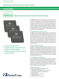
DATASHEET<strong>SQ</strong>-<strong>SI</strong>-360DASOLID-STATE MEMS INCLINOMETER±70 º DUAL AXIS, 360 º <strong>SI</strong>NGLE AXIS, SERIAL AND ANALOG OUTPUTEXAMPLE OUTPUT: HP AND LP VER<strong>SI</strong>ONS *EXAMPLE SUPPLY VOLTAGE+V cc 3.300 VSensitivity 0.01289 V/bitScale factor 0.00731 V/degOffset value 0.3300 VMax value 2.9552 VOutput Voltage (volts)Angle vs. Output Voltage3.5003.0002.5002.0001.5001.0000.5000.0000 90 180 270 0 90 180 270Angle (deg)Angle (deg)EXAMPLE ANGLE OUTPUT (BITS) OUTPUT (V)0 26 0.33510 31 0.39920 37 0.47730 43 0.55440 48 0.61850 54 0.69660 60 0.77370 65 0.83780 71 0.91590 77 0.992100 82 1.057110 88 1.134120 94 1.211130 99 1.276140 105 1.353150 111 1.430160 116 1.495170 122 1.572180 128 1.650190 133 1.714200 139 1.791210 145 1.869220 150 1.933230 156 2.010240 162 2.088250 167 2.152260 173 2.230270 179 2.307280 184 2.371290 190 2.449300 196 2.526310 201 2.591320 207 2.668330 213 2.745340 218 2.810350 224 2.887* For supply voltages other than 3.3V see the document “Inclinometer Worksheet” available at http://www.signalquest.comUpdated: 2008-09-08© <strong>SignalQuest</strong>, Inc.1999-200810 Water St.Lebanon, NH 03766 USATel: 603.448.6266Fax 603.619.6330www.signalquest.cominfo@signalquest.comPage 9 of 13
DATASHEET<strong>SQ</strong>-<strong>SI</strong>-360DASOLID-STATE MEMS INCLINOMETER±70 º DUAL AXIS, 360 º <strong>SI</strong>NGLE AXIS, SERIAL AND ANALOG OUTPUTORIENTATIONTERMINOLOGYGravity means a vector pointing from the device toward the center of the earth.X means a vector parallel to the white silkscreen arrow “X” printed on the main circuit board.Y means a vector parallel to the white silkscreen arrow “Y” printed on the main circuit board.Z means a vector passing through the white silkscreen dot “Z” printed on the main circuit board, at 90º to the board.Horizontal means the silkscreen arrow is pointing at a right angle to gravity.Straight Down means the silkscreen arrow is parallel to gravity.Straight Up means that the silkscreen arrow is anti-parallel to gravity (i.e. pointing toward the sky).Plumb Line is a line with a weight on the end hanging straight down.DUAL AXIS TILT MODEIn Dual Axis Tilt Mode the X Tilt and Y Tilt angles are measured between gravity and the white silkscreen arrows printed onthe main circuit board. If you passed a Plumb Line through the inclinometer’s X, Y, Z origin, the X and Y Tilt angles couldbe measured by placing a protractor’s straight edge on the plum line and then reading the angles made with each arrow.Y Tilt = Pitch (first angle)X Tilt = Roll (second angle)Holding Y HorizontalWhen X is Horizontal, X Tilt = 90 º.When X is Straight Up, X Tilt = ~180 º.When X is Straight Down, X Tilt = ~0 º.Holding X HorizontalWhen Y is Horizontal, Y Tilt = 90 º.When Y is Straight Up, Y Tilt = ~180 º.When Y is Straight Down, Y Tilt = ~0 º.<strong>SI</strong>NGLE AXIS GIMBALED MODEIn Single Axis Gimbaled Mode, the Z Rotation angle is defined as a rotation about the Z axis of the device. Typically, theinclinometer will be mounted using the VMP package for Single Axis Gimbaled Mode operation. For the Z Axis Rotationangle to remain in range, the Z Axis must be near horizontal. The Z axis should be kept to less than ± 45 º of deviation fromhorizontal..When X is Horizontal, Y is Straight Up, Z Rotation = 0 / 360 º.When Y is Horizontal, X is Straight Down, Z Rotation = 90 º.When X is Horizontal, Y is Straight Down, Z Rotation = 180 º.When Y is Horizontal, X is Straight Up, Z Rotation = 270 º.IMPORTANT NOTES• Regardless of the mode, the inclinometer measures angles with respect to gravity. It cannot measure rotation aboutthe gravity vector. All rotations about gravity are invisible to the sensor and are considered equivalent.Updated: 2008-09-08© <strong>SignalQuest</strong>, Inc.1999-200810 Water St.Lebanon, NH 03766 USATel: 603.448.6266Fax 603.619.6330www.signalquest.cominfo@signalquest.comPage 10 of 13
DATASHEET<strong>SQ</strong>-<strong>SI</strong>-360DASOLID-STATE MEMS INCLINOMETER±70 º DUAL AXIS, 360 º <strong>SI</strong>NGLE AXIS, SERIAL AND ANALOG OUTPUTORDERING GUIDEOPTIONS CODE OPTION NOTESPowerregulatoroptionPin packageoptionPerformanceoption-NR No onboard regulator Special order only-3.0R 3.0 V onboard regulator Special order only-3.3R 3.3 V onboard regulator Standard version (stock)-HMP Horizontal mount package Fits into standard 0.100” grid circuit board-VMP Vertical mount packageAvailable for <strong>SQ</strong>-<strong>SI</strong> family only-NP No pins installedFits inside potting box enclosures (<strong>SQ</strong>-ENCL-1)-HP High performanceBetter if power consumption is not a primary concern-LP Low powerBetter if low power consumption is critical-ULP Ultra low power Pre-release version available now-IND High accuracy Suitable for industrial applications needing precise measurementAccuracy-LC Low cost Suitable for high volume, lower accuracy, cost sensitive applications-S 500 mS settling time Better noise rejection, slower response time –Damping option(used for HP and LP versiononly)OtheroptionThis model uses a 0.5 second moving average filter to provide digitaldamping. This reduces the impact that spurious accelerations andvibrations have on the angle reading. This model will reject noisebetter than the “F” model, but with the tradeoff of a slower responsetime.-F 100 mS settling time Faster response time, poorer noise rejection –-CustomCustomer-specificrequirementsThis model uses a 0.1 second moving average filter to provide digitaldamping. This model will respond more quickly to changes in anglethan the “S” model, but with the trade off of poorer noise rejection.Please contact <strong>SignalQuest</strong> if you require an option not listed in thistable. For example, various baud rates, setting times, update rates andvoltage regulator options may be available on request.EXAMPLE PART NUMBER<strong>SQ</strong>-<strong>SI</strong>-360DA-3.3R-HMP-IND-HP-SACCESSORIESPART NUMBERDESCRIPTION<strong>SQ</strong>-USB2-TTL ■ Self-powering USB cable used to directly connect device to a PC.■ Installs a “virtual COM port” on host PC (i.e. COM 3).Updated: 2008-09-08© <strong>SignalQuest</strong>, Inc.1999-200810 Water St.Lebanon, NH 03766 USATel: 603.448.6266Fax 603.619.6330www.signalquest.cominfo@signalquest.comPage 11 of 13
DATASHEET<strong>SQ</strong>-<strong>SI</strong>-360DASOLID-STATE MEMS INCLINOMETER±70 º DUAL AXIS, 360 º <strong>SI</strong>NGLE AXIS, SERIAL AND ANALOG OUTPUT■ Converts PC voltage levels to device voltage levels and supplies power.■ Allows multiple devices to be easily connected to a single computer.■ Compatible with SignalVIEW real time display and data logging software.■ DLL provided for custom application development in VC++, C#, VB, etc…<strong>SQ</strong>-RS232-TTL ■ Same as above cable, but external power is required for devices without –LP option.<strong>SQ</strong>-ENCL-1 ■ Potting box enclosure. Fits models without pins installed (-NP option). Order one if using <strong>SQ</strong>-<strong>SI</strong> family or two if ordering <strong>SQ</strong>-<strong>SI</strong>2X family.Updated: 2008-09-08© <strong>SignalQuest</strong>, Inc.1999-200810 Water St.Lebanon, NH 03766 USATel: 603.448.6266Fax 603.619.6330www.signalquest.cominfo@signalquest.comPage 12 of 13
DATASHEET<strong>SQ</strong>-<strong>SI</strong>-360DASOLID-STATE MEMS INCLINOMETER±70 º DUAL AXIS, 360 º <strong>SI</strong>NGLE AXIS, SERIAL AND ANALOG OUTPUTLIMITATIONS AND WARNINGSLIFE SAFETYThis product is not designed for use in life support and/or safety equipment where malfunction of the product can reasonablybe expected to result in personal injury or death. Buyer uses this product in such applications at Buyer’s own risk and agreesto defend, indemnify, and hold harmless <strong>SignalQuest</strong>, Inc. from any and all damages, claims, suits, or expenses resulting fromsuch misuse.DYNAMIC ENVIRONMENTSThe device is designed to be used to measure angles in a quasi-static environment where external vibrations and accelerationsare kept to a minimum. Digital and analog signal processing methods are employed to reduce the effects of transientacceleration and small vibrations on the angle reading; however, under dynamic conditions where external accelerations orvibrations are present, the sensor’s performance may be degraded.VARIATIONS IN EARTH’S GRAVITYThis device is designed to be used near the earth’s surface only. Substantial changes in gravity will degrade the performanceof the sensor. This device is not intended or qualified to be used in aviation.TESTINGThe performance of each system is verified through build-time testing. Each system is tested before and after factorycalibration to ensure reliable performance.SYSTEM INTEGRATION TESTINGThorough testing should be carried out prior to product release to ensure system integration has not introduced unforeseenproblems. The system integrator assumes the ultimate responsibility for the safety of the target application.NOTICEInformation furnished by <strong>SignalQuest</strong>, Inc is believed to be accurate and reliable. However, this document may containERRORS and OMMI<strong>SI</strong>ONS. Accordingly, the design engineer should use this document as a reference rather than a strictdesign guideline and should perform thorough testing of any product that incorporates this or any other <strong>SignalQuest</strong> product.No responsibility is assumed by <strong>SignalQuest</strong>, Inc. for this use of this information, or for any infringements of patents or otherrights of third parties that may result from its use. Specifications are subject to change without notice. No license is grantedby implication or otherwise under any patent or patent rights of <strong>SignalQuest</strong>, Inc. Trademarks and registered trademarks arethe property of their respective companies.FURTHER INFORMATIONFor pricing, delivery, and ordering information, please contact <strong>SignalQuest</strong> at (603) 448-6266For updates on this and other documents, visit our website at www.signalquest.comUpdated: 2008-09-08© <strong>SignalQuest</strong>, Inc.1999-200810 Water St.Lebanon, NH 03766 USATel: 603.448.6266Fax 603.619.6330www.signalquest.cominfo@signalquest.comPage 13 of 13