harmonic distortion analysis in armature currents of ... - Komel
harmonic distortion analysis in armature currents of ... - Komel
harmonic distortion analysis in armature currents of ... - Komel

Create successful ePaper yourself
Turn your PDF publications into a flip-book with our unique Google optimized e-Paper software.
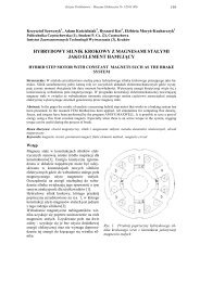
Zeszyty Problemowe – Maszyny Elektryczne Nr 84/2009 217Krzyszt<strong>of</strong> Ludw<strong>in</strong>ek * , Arkadiusz Siedlarz *** Kielce University <strong>of</strong> Technology, Kielce** Pilk<strong>in</strong>gton Automotive Poland Sp. z o.o., SandomierzHARMONIC DISTORTION ANALYSIS IN ARMATURE CURRENTSOF SYNCHRONOUS MACHINE DURING CO-OPERATIONWITH THE POWER SYSTEMAbstract: In the article an <strong>analysis</strong> <strong>of</strong> <strong>harmonic</strong> <strong>distortion</strong> <strong>in</strong> <strong>armature</strong> <strong>currents</strong> <strong>in</strong> synchronous mach<strong>in</strong>e dur<strong>in</strong>gco-operation with electric power system is presented. The <strong>analysis</strong> is carried out thanks to the computer applicationsdesigned <strong>in</strong> LabVIEW - graphical programm<strong>in</strong>g environment. The applications allow to carry out the<strong>analysis</strong> <strong>of</strong> the <strong>in</strong>fluence <strong>of</strong> voltage unbalance and <strong>harmonic</strong> <strong>distortion</strong> on the power quality and to display onscreen the non-s<strong>in</strong>e waveforms <strong>of</strong> the voltages and <strong>currents</strong> taken by electrical equipment. Moreover, the programsdisplay the RMS values <strong>of</strong> active, reactive and apparent power as well as power <strong>of</strong> <strong>distortion</strong> and coefficients:THD, PHD, IHD, power factor and voltage unbalance. In addition, the applications allow to recordthe signals from A/C measur<strong>in</strong>g devices or oscilloscopes and save them to file for further <strong>analysis</strong>.1. IntroductionDue to the fact that power supply market <strong>in</strong>Poland has gradually been freed from governmentregulations, producers and consumers <strong>of</strong>electrical energy pay more attention to its qualityand reliability <strong>of</strong> power system. Bad powerquality <strong>in</strong>creases its total loss dur<strong>in</strong>g transmission,could be a reason <strong>of</strong> serious mach<strong>in</strong>e failureslead<strong>in</strong>g to reduction <strong>of</strong> the productionvolume or to down-time <strong>in</strong>crease. Moreover, itcontributes to shorten<strong>in</strong>g <strong>of</strong> total lifetime <strong>of</strong> theelectrical mach<strong>in</strong>es. The problem <strong>of</strong> bad powerquality concerns not only <strong>in</strong>dustrial consumersbut also <strong>in</strong>dividual people. Flicker<strong>in</strong>g <strong>of</strong> light,<strong>of</strong>ten computers failures and data loss, improper<strong>in</strong>terruption <strong>of</strong> the circuits by fuses, circuitbreakers or RCDs, or electrical and electronicdevice overheat<strong>in</strong>g are only a few example <strong>of</strong>how big the impact <strong>of</strong> bad power quality on thelife <strong>of</strong> ord<strong>in</strong>ary people is. Thus, Polish workmarket needs eng<strong>in</strong>eers qualified to deal withthis issue. However, Universities <strong>in</strong> Poland donot spare much time for teach<strong>in</strong>g young eng<strong>in</strong>eersabout this matter. Therefore, Chair <strong>of</strong>Electrical Mach<strong>in</strong>es and Mechatronic Systems(KMEiSM) <strong>of</strong> Kielce University <strong>of</strong> Technologycreated lab stations to start educat<strong>in</strong>g students<strong>in</strong> the field <strong>of</strong> power quality. The lab stationsmake possible for the students to analyse theparameters <strong>of</strong> electrical energy, to display themomentary waveforms <strong>of</strong> the current, voltage,and momentary power and to carry out somesimulations <strong>of</strong> the <strong>in</strong>fluence <strong>of</strong> asymmetrical<strong>currents</strong> and voltage on the quality <strong>of</strong> energyand mach<strong>in</strong>es’ work.2. Computer measurement set for the<strong>analysis</strong> <strong>of</strong> higher <strong>harmonic</strong>s <strong>in</strong> <strong>currents</strong>and voltagesComputer measurement set enables to carry outan <strong>analysis</strong> <strong>of</strong> higher <strong>harmonic</strong>s <strong>in</strong> <strong>currents</strong> andvoltages supply<strong>in</strong>g 1-, 2-, or 3-phase electricalmach<strong>in</strong>es or electrical equipment. The computermeasurement set consists <strong>of</strong> both: measurementset and computer applications <strong>in</strong>LabVIEW 8.2 (simulation and <strong>analysis</strong>). Theseapplications allow to carry out the real-time<strong>analysis</strong> (to calculate the coefficients THD,PHD, IHD, power factor, unsymmetrical factor,powers: active P, reactive, Q, apparent S, modulusapparent S and <strong>distortion</strong> T) or to recordthe waveforms <strong>of</strong> <strong>currents</strong> and voltages for later<strong>analysis</strong>. The measurement set consists <strong>of</strong> 8measur<strong>in</strong>g transducers, designed and made <strong>in</strong>Chair <strong>of</strong> Electrical Mach<strong>in</strong>es and MechatronicSystems, for record<strong>in</strong>g the <strong>currents</strong> and voltagewaveforms (<strong>in</strong> phase and <strong>in</strong>terfacial configuration).2.1. Applications <strong>in</strong> LabVIEW - SimulatorThe simulator allows to generate arbitrary signalsby an appropriate set up <strong>of</strong> the amplitudesand <strong>in</strong>itials phases <strong>of</strong> particular <strong>harmonic</strong>s currentand voltages. Students can do that by tap<strong>in</strong>gthe values directly from the keyboard orby chang<strong>in</strong>g position <strong>of</strong> sliders on the screen.Follow<strong>in</strong>g <strong>analysis</strong> can be carried out:1) Analysis <strong>of</strong> voltage unbalance and higher<strong>harmonic</strong>s <strong>distortion</strong> <strong>in</strong> current and voltageand their the <strong>in</strong>fluence on the power quality <strong>in</strong>
Zeszyty Problemowe – Maszyny Elektryczne Nr 84/2009 219The Front Panel has got four w<strong>in</strong>dows. Firsttwo <strong>of</strong> them (Ustawianie parametrów napięciaand Ustawianie paramentrów prądu) can beused for sett<strong>in</strong>g parameters <strong>of</strong> arbitrary non-s<strong>in</strong>esignals by chang<strong>in</strong>g amplitudes and phases <strong>of</strong>particular <strong>harmonic</strong>s. If we assume that one <strong>of</strong>the signals is current and the other is voltage,some calculations can be done. The results <strong>of</strong>the calculations are presented <strong>in</strong> w<strong>in</strong>dow 3 –Wyniki, where RMS values <strong>of</strong> current and voltageas well as powers: apparent (S), active (P),reactive (Q) and <strong>distortion</strong> (T) and Power Factorare displayed. Calculations are done accord<strong>in</strong>gto follow<strong>in</strong>g formulas:From def<strong>in</strong>ition <strong>of</strong> real power <strong>of</strong> fundamental<strong>harmonic</strong>, the real power <strong>of</strong> n <strong>harmonic</strong> can beexpressed by:Pn U I cos(1)nnnand the total active power as a sum <strong>of</strong> <strong>in</strong>dividual<strong>harmonic</strong> products <strong>of</strong> voltage and current n:kP A A U I cos P U I cos0i 0u n n n 0 n n nn1 n150 (2)where: U n , I n – RMS voltage and current <strong>harmonic</strong>s,A 0i , A 0u – voltage and current constantcomponent.For a given cos n the value <strong>of</strong> s<strong>in</strong> n can becalculated as well as the reactive powers for<strong>harmonic</strong>s n:Qn U I s<strong>in</strong>(3)nnnand the total reactive power as a sum <strong>of</strong> <strong>in</strong>dividual<strong>harmonic</strong> products <strong>of</strong> voltage and currentn:50Q U I s<strong>in</strong>(4)n1n nnModulus apparent power as <strong>in</strong>dicated <strong>in</strong> [6] isdescribed as:50 50 12 2 2n nn0 n0S U I ( U I ) (5)and apparent power is described as:2 2 2S P Q(6)Powers <strong>in</strong> equation (5) and (6) are not equal.Accord<strong>in</strong>g to the theory <strong>of</strong> Budenau the differencebetween them can be expla<strong>in</strong>ed by socalled power <strong>of</strong> <strong>distortion</strong> (T). The relationsbetween the powers can be expressed by:2 2S P Q T2(7)As stated <strong>in</strong> [6] the above formula is controversial.Thus, <strong>in</strong> the paper <strong>in</strong> LabView applicationsthe real and reactive powers for all <strong>harmonic</strong>sare calculated separately on the basis <strong>of</strong> theRMS values <strong>of</strong> current and voltage <strong>of</strong> particular<strong>harmonic</strong>s, as well as cos n and s<strong>in</strong>.Power factor can be described as:PPF S50n1U I cosn n nU I(8)All values are displayed on screen. It is alsopossible to save the calculation to the txt file.All the calculations are carried out by the subprograms<strong>in</strong> LabView and have been showed <strong>in</strong>separated w<strong>in</strong>dows Front Panel.Fig. 3. Block Diagram Obliczenia.vi
222Zeszyty Problemowe – Maszyny Elektryczne Nr 84/2009which were recorded dur<strong>in</strong>g measurements anda percentage participation <strong>of</strong> all <strong>armature</strong> current<strong>harmonic</strong>s (IHD i% up to 40 th ) <strong>in</strong> relation t<strong>of</strong>undamental <strong>harmonic</strong> and <strong>in</strong> relation to nom<strong>in</strong>alfundamental <strong>harmonic</strong>. Fundamental<strong>harmonic</strong>s <strong>of</strong> current ant voltage is not shown).a)IHDu%b)IHDi%c)IHDIN %2,01,51,00,50,0504030201006543210P = 1.1 kW , Q=-5.2kVArP = 1.1 kW , Q=-2.3kVArP = 1.1 kW , Q=-0.5kVArP = 1.1 kW , Q=0.7kVArP = 1.1 kW , Q=3.8kVAr3 5 7 9 11 13 15 17 19 21 23 25 27 29 31 33 35 37 39Harmonics - nP = 1.1 kW , Q=-5.2kVArP = 1.1 kW , Q=-2.3kVArP = 1.1 kW , Q=-0.5kVArP = 1.1 kW , Q=0.7kVArP = 1.1 kW , Q=3.8kVAr3 5 7 9 11 13 15 17 19 21 23 25 27 29 31 33 35 37 39Harmonics - nP = 1.1 kW , Q=-5.2kVArP = 1.1 kW , Q=-2.3kVArP = 1.1 kW , Q=-0.5kVArP = 1.1 kW , Q=0.7kVArP = 1.1 kW , Q=3.8kVAr3 5 7 9 11 13 15 17 19 21 23 25 27 29 31 33 35 37 39Harmonics - nFig. 8. Percentage participation <strong>of</strong> a) voltage<strong>harmonic</strong>s and <strong>armature</strong> current <strong>harmonic</strong>s <strong>in</strong>relation to b) fundamental <strong>harmonic</strong> andc) nom<strong>in</strong>al fundamental <strong>harmonic</strong>Table 1. Sett<strong>in</strong>g-up <strong>of</strong> IHD and THD up to 40 th <strong>harmonic</strong>sHarm.nAnalyz<strong>in</strong>g the compilation presented <strong>in</strong> Fig. 8 itcan be noticed that the <strong>harmonic</strong>s <strong>in</strong> the voltage<strong>of</strong> supply<strong>in</strong>g system have got nearly constantvalues. Small variation (< 0.5% U (1) ) can beobserved only for <strong>harmonic</strong> 5. Analyz<strong>in</strong>g thestatements presented <strong>in</strong> Fig. 8 it can be noticedthat the <strong>harmonic</strong>s <strong>of</strong> <strong>armature</strong> current have gotnearly constant values. Small variations(< 0,2 A) <strong>of</strong> <strong>harmonic</strong> 5 results from the variations<strong>of</strong> the same <strong>harmonic</strong> <strong>in</strong> the supply<strong>in</strong>gvoltage dur<strong>in</strong>g carry<strong>in</strong>g out the measurements[7, 8]. However, <strong>in</strong> case <strong>of</strong> comparison the<strong>harmonic</strong>s content not <strong>in</strong> relation to nom<strong>in</strong>alfundamental <strong>harmonic</strong> <strong>of</strong> <strong>armature</strong> current but<strong>in</strong> relation to fundamental <strong>harmonic</strong>, then forexample IHD I% for the 5 <strong>harmonic</strong>s result differseven about forty percentage – Table 1.Fig. 8 shows a comparison <strong>of</strong> the <strong>harmonic</strong>scontent not only <strong>in</strong> reference to fundamental<strong>harmonic</strong> <strong>of</strong> <strong>armature</strong> current, as <strong>of</strong>ten found <strong>in</strong>literature but <strong>in</strong> relation to value <strong>of</strong> fundamental<strong>harmonic</strong> <strong>of</strong> nom<strong>in</strong>al current as imposed <strong>in</strong> PN-EN 61000-3-12 for equipment with nom<strong>in</strong>alcurrent > 16 A and < 75 A.Sett<strong>in</strong>g-up <strong>of</strong> <strong>in</strong>dividual <strong>harmonic</strong> <strong>distortion</strong>(IHD) and Total <strong>harmonic</strong> <strong>distortion</strong> (THD)coefficient for presented <strong>harmonic</strong> voltages and<strong>armature</strong> <strong>currents</strong> <strong>in</strong> Fig. 9a and Fig. 9b aregiven <strong>in</strong> the Table 1.P = 1,1 kW Q = -5,2 kVAr P = 1,1 kW Q = -2,3 kVAr P = 1,1 kW Q = -0,5 kVAr P = 1,1 kW Q = 0,7 kVAr P = 1,1 kW Q = 3,8 kVArIHDi I IHDu U IHDi I IHDu U IHDi I IHDu U IHDi I IHDu U IHDi I IHDu U[%] [A] [%] [V] [%] [A] [%] [V] [%] [A] [%] [V] [%] [A] [%] [V] [%] [A] [%] [V]1 100,0 7,99 100,0 219,5 100,0 3,84 100,0 222,2 100,0 1,90 100,0 222,0 100,0 2,10 100,0 222,9 100,0 6,10 100,0 222,83 2,17 0,17 0,45 0,99 4,33 0,17 0,46 1,02 8,70 0,16 0,45 1,00 8,81 0,18 0,49 1,10 3,42 0,21 0,45 0,995 8,07 0,64 1,48 3,25 20,44 0,78 1,68 3,73 47,29 0,86 1,82 4,03 36,14 0,75 1,51 3,37 12,44 0,76 1,53 3,417 0,99 0,08 0,80 1,76 2,32 0,09 0,77 1,70 5,43 0,10 0,73 1,63 3,50 0,07 0,80 1,78 1,74 0,10 0,73 1,629 0,39 0,03 0,16 0,36 0,83 0,03 0,17 0,37 1,56 0,03 0,14 0,32 1,08 0,02 0,18 0,40 0,34 0,02 0,16 0,3511 2,59 0,21 0,09 0,19 5,55 0,21 0,11 0,23 11,44 0,21 0,09 0,20 9,71 0,20 0,14 0,31 3,52 0,21 0,09 0,1913 2,80 0,22 0,15 0,33 5,62 0,21 0,16 0,36 11,21 0,20 0,14 0,31 9,74 0,20 0,18 0,39 2,91 0,18 0,13 0,2915 0,20 0,02 0,16 0,35 0,27 0,01 0,12 0,26 1,21 0,02 0,15 0,32 0,56 0,01 0,11 0,24 0,35 0,02 0,15 0,3317 0,68 0,05 0,12 0,27 1,33 0,05 0,18 0,40 2,04 0,04 0,13 0,30 2,13 0,04 0,13 0,29 1,26 0,08 0,08 0,1819 0,30 0,02 0,07 0,14 0,77 0,03 0,09 0,19 1,66 0,03 0,06 0,13 1,78 0,04 0,10 0,22 0,59 0,04 0,10 0,2335 0,94 0,08 0,08 0,19 1,85 0,07 0,09 0,21 3,23 0,06 0,09 0,21 2,55 0,05 0,06 0,13 0,78 0,05 0,09 0,2137 1,18 0,09 0,06 0,13 2,54 0,10 0,10 0,22 5,34 0,10 0,09 0,19 4,80 0,10 0,07 0,15 1,70 0,10 0,07 0,16THD%9,51 1,84 22,88 2,00 51,71 2,1 40,49 1,87 14,41 1,824. ConclusionsIn the article, the <strong>analysis</strong> <strong>of</strong> higher <strong>harmonic</strong>contents <strong>in</strong> <strong>currents</strong> and voltages <strong>of</strong> synchronousmach<strong>in</strong>e <strong>armature</strong> dur<strong>in</strong>g co-operationwith the electric supply system has been presented.The <strong>analysis</strong> <strong>of</strong> higher <strong>harmonic</strong> contentshas been carried out <strong>in</strong> applications made<strong>in</strong> LabView graphical programm<strong>in</strong>g environment.The designed graphical applications allowto display the waveforms <strong>of</strong> voltages and
Zeszyty Problemowe – Maszyny Elektryczne Nr 84/2009 223<strong>currents</strong> taken by arbitrary electrical equipment.Additionally, the applications can carry outcalculations <strong>of</strong> RMS values <strong>of</strong> Apparent Power(S), Real Power (P), Reactive Power (Q),Power <strong>of</strong> Distortion (D) as well as Power Factorand coefficients THD, PHD, IHD, and voltageunbalance. Application Analizator jakości.viallows also to carry out an <strong>analysis</strong> <strong>of</strong>previously recorded waveforms <strong>of</strong> current andvoltages. Analys<strong>in</strong>g the <strong>harmonic</strong> spectrum <strong>of</strong><strong>armature</strong> <strong>currents</strong> <strong>in</strong> synchronous mach<strong>in</strong>e dur<strong>in</strong>gco-operation with supply system, it can benoticed that the content <strong>of</strong> <strong>harmonic</strong>s 3, 5 and 7is the most significant. So called slot <strong>harmonic</strong>s,<strong>in</strong> our case No 11, 13 and 35, 37, comefrom the design <strong>of</strong> the mach<strong>in</strong>e itself, which hasgot 12 alum<strong>in</strong>ium bars (squirrel-cage) <strong>in</strong> therotor and 36 slots <strong>in</strong> the stator.The synchronous generator meets specifiedrequirements <strong>in</strong> the standard PN-EN 61000-3-2 regard<strong>in</strong>g <strong>harmonic</strong> <strong>distortion</strong>. This norm,depend<strong>in</strong>g on the equipment characteristic,determ<strong>in</strong>es the limits for particular <strong>harmonic</strong>s.However, it is not clearly stated to what value,RMS <strong>of</strong> fundamental <strong>harmonic</strong> <strong>of</strong> current orRMS <strong>of</strong> nom<strong>in</strong>al fundamental <strong>harmonic</strong> current<strong>of</strong> the mach<strong>in</strong>e (as determ<strong>in</strong>ed <strong>in</strong> PN-EN61000-3-12) for particular <strong>harmonic</strong>s should bereferenced. In case <strong>of</strong> <strong>in</strong>dividual co-operation <strong>of</strong>the electrical mach<strong>in</strong>e with electrical powersystem commonly used THD I% and IHD I% coefficientsdo not give unequivocal answer to thecontent <strong>of</strong> higher <strong>harmonic</strong>s <strong>in</strong> the <strong>armature</strong><strong>currents</strong>. The <strong>analysis</strong> <strong>of</strong> the <strong>in</strong>dividual work <strong>of</strong>synchronous mach<strong>in</strong>e dur<strong>in</strong>g co-operation withpower system proved that THD I% and IHD I%coefficients have different values depend<strong>in</strong>g onhow the mach<strong>in</strong>e is loaded (Fig. 6 – Fig. 7 andTable 1). RMS values <strong>of</strong> the voltage <strong>harmonic</strong>sbasically almost do not change. If synchronousgenerator is loaded with P = 1,1 kW and Q =-5,2 kVAr (reactive power taken from the system)the THDi % coefficient is equaled to 9,5%.If generator is loaded with P = 1,1 kW and Q =-0,5 kVAr the THDi % is equaled to 51,7%.However, RMS values <strong>of</strong> the current <strong>harmonic</strong>srema<strong>in</strong>ed at similar level <strong>in</strong> the whole range andsmall changes came from the fact <strong>of</strong> <strong>harmonic</strong>variations <strong>in</strong> the supply<strong>in</strong>g voltage [6, 7]. Similarvariations <strong>of</strong> THD I% and IHD I% coefficientscould be noticed when the synchronous mach<strong>in</strong>ehave been <strong>in</strong> the state <strong>of</strong> overexcitation.Comparison <strong>of</strong> <strong>in</strong>dividual contents <strong>of</strong> <strong>harmonic</strong>s<strong>in</strong> <strong>armature</strong> <strong>currents</strong> registered <strong>in</strong> measurementset and <strong>in</strong> relation to nom<strong>in</strong>al fundamentalcomponent are presented <strong>in</strong> Fig. 8.Comparison <strong>of</strong> <strong>harmonic</strong> contents <strong>in</strong> <strong>armature</strong><strong>currents</strong> unambiguously results, that <strong>in</strong> case <strong>of</strong><strong>in</strong>dividual co-operation electric mach<strong>in</strong>e withelectric power system <strong>in</strong> wide range <strong>of</strong> loadvariations more reliable <strong>in</strong>formation about THDand <strong>in</strong>dividual <strong>harmonic</strong> contents is <strong>in</strong> relationto nom<strong>in</strong>al fundamental component then t<strong>of</strong>undamental component.5. Bibliography[1] Z. Ko walski: The Quality <strong>of</strong> Electrical Energy.Monograph. Technical University <strong>of</strong> Lodz, Łódź 2007,Poland (<strong>in</strong> Polish)[2] A. Siedlarz: Analysis and visualization <strong>of</strong> <strong>in</strong>fluenceunsymmetrical and <strong>distortion</strong> <strong>of</strong> power supply systemvoltages and <strong>currents</strong> on the quality <strong>of</strong> electrical energy <strong>in</strong>LabView. Master’s thesis. Kielce University <strong>of</strong> Technology.Kielce 2008, Poland (<strong>in</strong> Polish)[3] PN-EN 50160: Voltage characteristics <strong>of</strong> electricitysupplied by public distribution systems. PKN, Warszawa2008, Poland (<strong>in</strong> Polish)[4] PN-EN 61000-3-2: Electromagnetic compatibility(EMC) Part 3-2: Limits - Limits for <strong>harmonic</strong> currentemmissions (equipment <strong>in</strong>put current ≤16A per phase)PKN, Warszawa 2007, Poland (<strong>in</strong> Polish)[5] PN - EN 61000-3-12: Electromagnetic compatibility(EMC) Part 3-12: Limits - Limits for <strong>harmonic</strong> currentproduced by equipment connected to public low-voltagesystems with <strong>in</strong>put current >16A and ≤75A per phase.PKN, Warszawa 2005, Poland (<strong>in</strong> Polish)[6] Czarnecki L. S.: Moc bierna i deformacji wedługdef<strong>in</strong>icji Budenau i przyczyny bezużyteczności tychwielkości w elektrotechnice. ZNPŚl, Elektryka 107, Gliwice1989, pp. 41-51[7] S. Wiak, R. Nadolski, K. Lud w<strong>in</strong>ek,J. Staszak: Influence <strong>of</strong> the Synchronous Cyl<strong>in</strong>dricalMach<strong>in</strong>e Damp<strong>in</strong>g Cage on Content <strong>of</strong> Higher Harmonics<strong>in</strong> Armature Currents Dur<strong>in</strong>g Co-Operation with theDistorted and Asymmetrical Electric Power System ComputerEng<strong>in</strong>eer<strong>in</strong>g <strong>in</strong> Applied Electromagnetism, IOSPress, 2006, pp. 520-527[8] K. Lud w<strong>in</strong>ek: Nons<strong>in</strong>usoidal and unsymmetrical<strong>in</strong>fluence <strong>of</strong> electric power system on <strong>armature</strong> <strong>currents</strong>waveforms <strong>in</strong> synchronous mach<strong>in</strong>e, Zeszyty NaukowePolitechniki Świętokrzyskiej – Elektryka 42, Kielce 2005,pp. 251-266, Poland (<strong>in</strong> Polish)AuthorsDSc. Krzyszt<strong>of</strong> Ludw<strong>in</strong>ek,e–mail: k.ludw<strong>in</strong>ek@tu.kielce.plKielce University <strong>of</strong> Technology,Al. Tysiąclecia PP. 7, 25–314 Kielce, Poland,MSc. Arkadiusz Siedlarz,e–mail: arkadiusz.siedlarz@gmail.comPilk<strong>in</strong>gton Automotive Poland Sp. z o.o.ul. Portowa 24, 27-600 Sandomierz, Poland