AC Frequency Inverters NXP / NXC - Andantex UK
AC Frequency Inverters NXP / NXC - Andantex UK
AC Frequency Inverters NXP / NXC - Andantex UK

You also want an ePaper? Increase the reach of your titles
YUMPU automatically turns print PDFs into web optimized ePapers that Google loves.
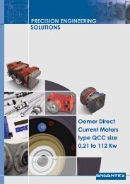
PRECISION ENGINEERINGSOLUTIONSVacon <strong>AC</strong><strong>Frequency</strong><strong>Inverters</strong>type <strong>NXP</strong> & <strong>NXC</strong>High Performance
the dynamic choiceThe Vacon <strong>NXP</strong> is a state-of-art <strong>AC</strong> drive for use in all applications where robustness,dynamic performance, precision and power are required.The quality and reliability of a machine or a process is in mostcases the result of a precise and dynamic control of <strong>AC</strong> motors.The Vacon <strong>NXP</strong> has been designed to provide the best possiblecontrol under all circumstances and thus to ensure a high operationalquality and availability for the entire lifetime of thesystem.A forerunner in designing and manufacturing <strong>AC</strong> drives, Vaconhas developed innovative solutions and leading-edge technologyfor demanding applications and high powers.Features• Complete power and voltage range• Wide set of applications adapts the Vacon <strong>NXP</strong>to virtually any need• Controls induction and permanent magnet motors• Dynamic open and closed loop vector control• Complete range of communications and I/O options• Fast drive to drive communicationBy bringing these solutions to the customer the Vacon <strong>NXP</strong>offers new opportunities and helps to create the best and mostinnovative products and to reach the most challenging targets.Snap-on fanRobust powermoduleRemovabledisplayConnection toPC or doorinstallation kitTouch-protectedconnectionsSeparatecontrol unit,flexible I/Ointerfacefr4—fr9fr4 fr5 fr6 fr7 fr8 fr92
top-class flexibilityThe Vacon <strong>NXP</strong> offers, in addition to its control characteristics, a wide choice of products andcabinets for the varying needs in the high-power range.There are three models available to meet various customerneeds as follows:• Vacon <strong>NXP</strong> IP21/IP54 wall-mounted or stand-alone drivesfor installation wherever there is space available• Vacon <strong>NXP</strong> high-power IP00 drive modules forinstallation into the customer's cabinet• Vacon <strong>NXC</strong> robust cabinet drive with topflexibility and a wide range of optionsvacon nxpdrive modulesvacon nxpstand-alone drivesvacon nxccabinet drives3
wall-mounted vacon nxpFor the lower power range the Vacon <strong>NXP</strong> drives are available in a compact IP21 or IP54 enclosure.It is one of the most compact and complete drives on the market with all necessary componentsintegrated into one single enclosure.The wall-mounted units are equipped with internal EMC filtering, and the power electronics is integrated into an all-metal frame.The smaller frame sizes (FR4-FR6) have an integrated brake chopper as standard, and the 380-500 V units can be equipped with anintegrated brake resistor. The larger frames (FR7-FR9) can be equipped with an integrated brake chopper as standard/option.Mains voltage 208—240 V, 50/60 Hz, 3˜<strong>NXP</strong><strong>NXP</strong><strong>NXP</strong><strong>NXP</strong><strong>NXP</strong><strong>NXP</strong><strong>NXP</strong><strong>NXP</strong><strong>NXP</strong><strong>AC</strong> drive type0003000400070008001100120017002500312 A 2 H 1 SSS2 A 2 H 1 SSS2 A 2 H 1 SSS2 A 2 H 1 SSS2 A 2 H 1 SSS2 A 2 H 1 SSS2 A 2 H 1 SSS2 A 2 H 1 SSS2 A 2 H 1 SSS<strong>NXP</strong><strong>NXP</strong>004800612 A 2 H 1 SSS2 A 2 H 1 SSS<strong>NXP</strong> 0075 2 A 2 H 0 SSS<strong>NXP</strong> 0088 2 A 2 H 0 SSS<strong>NXP</strong> 0114 2 A 2 H 0 SSS<strong>NXP</strong><strong>NXP</strong><strong>NXP</strong><strong>NXP</strong><strong>NXP</strong>014001700205026103002 A 2 H 0 SSS2 A 2 H 0 SSS2 A 2 H 0 SSS2 A 2 H 0 SSF2 A 2 H 0 SSFLoadabilityMotor shaft powerLow (+40°C) High (+50°C) 230 V supplyRatedcontinuouscurrent I L (A)3.74.86.67.81112.517.525314861758811414017020526130010%overloadcurrent (A)4.15.37.38.612.113.819.327.534.152.867.18397125154187226287330Ratedcontinuouscurrent I H (A)2.43.74.86.67.81112.517.525314861758810514017020524550%overloadcurrent (A)3.65.67.29.911.716.518.826.337.546.572.092113132158210255308368Maximum 10%current I S overl.P (kW)4.87.49.613.215.62225355062961221501762102803363494440.550.751.11.52.2345.57.51115222230374555759050%overl.P (kW)0.370.550.751.11.52.2345.57.5111522223037455575FramesizeFR4FR4FR4FR4FR4FR4FR5FR5FR5FR6FR6FR7FR7FR7FR8FR8FR8FR9FR9DimensionsW*H*D (mm)128*292*190128*292*190128*292*190128*292*190128*292*190128*292*190144*391*214144*391*214144*391*214195*519*237195*519*237237*591*257237*591*257237*591*257285*721*288285*721*288285*721*288480*1150*362480*1150*362Mains voltage 380—500 V, 50/60 Hz, 3˜LoadabilityMotor shaft powerLow (+40°C) High (+50°C) 400 V supply<strong>AC</strong> drive typeRatedcontinuouscurrent I L (A)10%overloadcurrent (A)Ratedcontinuouscurrent I H (A)50%overloadcurrent (A)Maximum 10%current I S overl.P (kW)50%overl.P (kW)FramesizeDimensionsW*H*D (mm)<strong>NXP</strong><strong>NXP</strong><strong>NXP</strong><strong>NXP</strong><strong>NXP</strong><strong>NXP</strong><strong>NXP</strong><strong>NXP</strong><strong>NXP</strong><strong>NXP</strong><strong>NXP</strong><strong>NXP</strong><strong>NXP</strong><strong>NXP</strong><strong>NXP</strong><strong>NXP</strong><strong>NXP</strong><strong>NXP</strong><strong>NXP</strong><strong>NXP</strong>000300040005000700090012001600220031003800450061007200870105014001680205026103005 A 2 H 1 SSS5 A 2 H 1 SSS5 A 2 H 1 SSS5 A 2 H 1 SSS5 A 2 H 1 SSS5 A 2 H 1 SSS5 A 2 H 1 SSS5 A 2 H 1 SSS5 A 2 H 1 SSS5 A 2 H 1 SSS5 A 2 H 1 SSS5 A 2 H 1 SSS5 A 2 H 0 SSS5 A 2 H 0 SSS5 A 2 H 0 SSS5 A 2 H 0 SSS5 A 2 H 0 SSS5 A 2 H 0 SSS5 A 2 H 0 SSF5 A 2 H 0 SSF3.34.35.67.691216233138466172871051401702052613003.64.76.28.49.913.217.625.33442516779961161541872262873302.23.34.35.67.691216233138466172871051401702052453.35.06.58.411.413.518.024.035475769921081311582102553083684.46.28.610.814182432466276921221441742102803363494441.11.52.2345.57.5111518.5223037455575901101321600.751.11.52.2345.57.5111518.522303745557590110132FR4FR4FR4FR4FR4FR4FR5FR5FR5FR6FR6FR6FR7FR7FR7FR8FR8FR8FR9FR9128*292*190128*292*190128*292*190128*292*190128*292*190128*292*190144*391*214144*391*214144*391*214195*519*237195*519*237195*519*237237*591*257237*591*257237*591*257285*721*288285*721*288285*721*288480*1150*362480*1150*3624
wall-mounted vacon nxpMains voltage 525—690 V, 50/60 Hz, 3˜LoadabilityMotor shaft powerLow (+40°C) High (+50°C) 690 V supply<strong>AC</strong> drive typeRatedcontinuouscurrent I L (A)10%overloadcurrent (A)Ratedcontinuouscurrent I H (A)50%overloadcurrent (A)Maximum 10%current I S overl.P (kW)50%overl.P (kW)FramesizeDimensionsW*H*D (mm)<strong>NXP</strong><strong>NXP</strong><strong>NXP</strong><strong>NXP</strong><strong>NXP</strong><strong>NXP</strong><strong>NXP</strong><strong>NXP</strong><strong>NXP</strong>0004000500070010001300180022002700346 A 2 L 0 SSS6 A 2 L 0SSS6 A 2 L 0 SSS6 A 2 L 0 SSS6 A 2 L 0 SSS6 A 2 L 0 SSS6 A 2 L 0 SSS6 A 2 L 0 SSS6 A 2 L 0 SSS4.55.57.51013.5182227345.06.18.311.014.919.824.229.7373.24.55.57.51013.51822274.86.88.311.315.020.327.033.0416.49.011.015.020.027364454345.57.5111518.522302.2345.57.5111518.522FR6FR6FR6FR6FR6FR6FR6FR6FR6195*519*237195*519*237195*519*237195*519*237195*519*237195*519*237195*519*237195*519*237195*519*237<strong>NXP</strong><strong>NXP</strong>004100526 A 2 L 0 SSS6 A 2 L 0 SSS4152455734415162688237.5453037.5FR7FR7237*591*257237*591*257<strong>NXP</strong><strong>NXP</strong><strong>NXP</strong>0062008001006 A 2 L 0 SSS6 A 2 L 0 SSS6 A 2 L 0 SSS628010068881105262807893120104124160557590455575FR8FR8FR8285*721*288285*721*288285*721*288<strong>NXP</strong><strong>NXP</strong><strong>NXP</strong><strong>NXP</strong>01250144017002086 A 2 L 0 SSF6 A 2 L 0 SSF6 A 2 L 0 SSF6 A 2 L 0 SSF12514417020813815818722910012514417015018821625520021324528911013216020090110132160FR9FR9FR9FR9480*1150*362480*1150*362480*1150*362480*1150*3625
stand-alone vacon nxpHigh-power Vacon <strong>NXP</strong> drives are also available in a compact stand-alone IP21 or IP54 enclosure.These units are designed for use in applications where the drive has to be compact and easy to install.The Vacon <strong>NXP</strong> stand-alone drives are fully enclosed at the factory and are ready for installation immediately. The drive has integratedfuses as standard and no extra protections are required by the drive. It is also possible to equip the drive with an optionalintegrated load switch which further simplifies the handling in the field.Mains voltage 380—500 V, 50/60 Hz, 3˜LoadabilityMotor shaft power<strong>AC</strong> drive typeRatedcontinuouscurrentI L (A)Low (+40°C) High (+40°C) 400 V supply10%overloadcurrent(A)RatedcontinuouscurrentI H (A)50%overloadcurrent(A)Maximum 10%current I S overloadP (kW)50%overloadP (kW)FramesizeDimensionsW*H*D (mm)<strong>NXP</strong> 0385 5 A 2 L 0 SSA 385 424 300 450 540 200 160 FR10 595*2020*602<strong>NXP</strong> 0460 5 A 2 L 0 SSA 460 506 385 578 693 250 200 FR10 595*2020*602<strong>NXP</strong> 0520 5 A 2 L 0 SSA 520 572 460 690 828 250 250 FR10 595*2020*602Mains voltage 525—690 V, 50/60 Hz, 3˜LoadabilityMotor shaft power<strong>AC</strong> drive typeRatedcontinuouscurrentI L (A)Low (+40°C) High (+40°C) 690 V supply10%overloadcurrent(A)RatedcontinuouscurrentI H (A)50%overloadcurrent(A)Maximum 10%current I S overloadP (kW)50%overloadP (kW)FramesizeDimensionsW*H*D (mm)<strong>NXP</strong> 0261 6 A 2 L 0 SSA 261 287 208 312 375 250 200 FR10 595*2020*602<strong>NXP</strong> 0325 6 A 2 L 0 SSA 325 358 261 392 470 315 250 FR10 595*2020*602<strong>NXP</strong> 0385 6 A 2 L 0 SSA 385 424 325 488 585 355 315 FR10 595*2020*602<strong>NXP</strong> 0416 6 A 2 L 0 SSA # 416 458 325 488 585 400 315 FR10 595*2020*602# max. ambient temperature of +35˚Chardware configurationsFUNCTIONIP21IP54 (contact factory for details)Integrated fusesIntegrated load switchEMC filtering LEMC filtering TIntegrated brake chopper(cabling top entry)AVAILABILITYStandardOptionalStandardOptionalStandardOptionalOptional(H: +122 mm)6
ip00 vacon nxp modulesThe Vacon <strong>NXP</strong> high-power IP00 drive modules are intended for installation into a separate enclosure.Thanks to the robust and square-shaped design of the module, the enclosure design is easy andstraightforward.Mains voltage 380—500 V, 50/60 Hz, 3˜LoadabilityMotor shaft power<strong>AC</strong> drive typeLow (+40°C) High (+40°C) 400 V supplyRatedcontinuouscurrentI L (A)10%overloadcurrent(A)RatedcontinuouscurrentI H (A)50%overloadcurrent(A)Maximum 10%current I S overloadP (kW)50%overloadP (kW)FramesizeModuleW*H*D (mm)ChokesW*H*D (mm)<strong>NXP</strong> 0385 5 A 0 N 0 SSA 385 424 300 450 540 200 160 FR10 500*1165*506 350*383*262 1)<strong>NXP</strong> 0460 5 A 0 N 0 SSA 460 506 385 578 693 250 200 FR10 500*1165*506 497*399*244 1)<strong>NXP</strong> 0520 5 A 0 N 0 SSA 520 572 460 690 828 250 250 FR10 500*1165*506 497*399*244 1)<strong>NXP</strong> 0590 5 A 0 N 0 SSA 590 649 520 780 936 315 250 FR11 709*1206*506 2x(350*383*262)<strong>NXP</strong> 0650 5 A 0 N 0 SSA 650 715 590 885 1062 355 315 FR11 709*1206*506 2x(350*383*262)<strong>NXP</strong> 0730 5 A 0 N 0 SSA 730 803 650 975 1170 400 355 FR11 709*1206*506 2x(350*383*262)<strong>NXP</strong> 0820 5 A 0 N 0 SSA 820 902 730 1095 1314 450 400 FR12 2x(500*1165*506) 2x(497*399*244)<strong>NXP</strong> 0920 5 A 0 N 0 SSA 920 1012 820 1230 1476 500 450 FR12 2x(500*1165*506) 2x(497*399*244)<strong>NXP</strong> 1030 5 A 0 N 0 SSA 1030 1133 920 1380 1656 560 500 FR12 2x(500*1165*506) 2x(497*399*244)# max. ambient temperature of +35˚C 1) 12-pulse units, 2x(354*319*230)Mains voltage 525—690 V, 50/60 Hz, 3˜LoadabilityMotor shaft power<strong>AC</strong> drive typeLow (+40°C) High (+40°C) 690 V supplyRatedcontinuouscurrentI L (A)10%overloadcurrent(A)RatedcontinuouscurrentI H (A)50%overloadcurrent(A)Maximum 10%current I S overloadP (kW)50%overloadP (kW)FramesizeModuleW*H*D (mm)ChokesW*H*D (mm)<strong>NXP</strong> 0261 6 A 0 N 0 SSA 261 287 208 312 375 250 200 FR10 500*1165*506 354*319*230 1)<strong>NXP</strong> 0325 6 A 0 N 0 SSA 325 358 261 392 470 315 250 FR10 500*1165*506 350*383*262 1)<strong>NXP</strong> 0385 6 A 0 N 0 SSA 385 424 325 488 585 355 315 FR10 500*1165*506 350*383*262 1)<strong>NXP</strong> 0416 6 A 0 N 0 SSA # 416 458 325 488 585 400 315 FR10 500*1165*506 350*383*262 1)<strong>NXP</strong> 0460 6 A 0 N 0 SSA 460 506 385 578 693 450 355 FR11 709*1206*506 497*399*244 2)<strong>NXP</strong> 0502 6 A 0 N 0 SSA 502 552 460 690 828 500 450 FR11 709*1206*506 497*399*244 2)<strong>NXP</strong> 0590 6 A 0 N 0 SSA # 590 649 502 753 904 560 500 FR11 709*1206*506 2x(350*383*262)<strong>NXP</strong> 0650 6 A 0 N 0 SSA 650 715 590 885 1062 630 560 FR12 2x(500*1165*506) 2x(350*383*262)<strong>NXP</strong> 0750 6 A 0 N 0 SSA 750 825 650 975 1170 710 630 FR12 2x(500*1165*506) 2x(350*383*262)<strong>NXP</strong> 0820 6 A 0 N 0 SSA # 820 902 650 975 1170 800 630 FR12 2x(500*1165*506) 2x(350*383*262)# max. ambient temperature of +35˚C 1) 12-pulse units, 2x(354*319*230) 2) 12-pulse units, 2x(350*383*262)hardware configurationsFUNCTIONIntegrated control unitExternal control unitIntegrated brake chopper6-pulse supply12-pulse supplyEMC filtering NEMC filtering TAVAILABILITYStandardOptionalOptionalStandardOptionalStandardOptional7
vacon nxc, compact and flexibleThe Vacon <strong>NXC</strong> cabinet drive is compact and well tested, fully utilizing the flexibility of the Vacon <strong>NXP</strong>drive. The Vacon <strong>NXC</strong> is designed to meet the most demanding requirements on flexibility, robustness,compactness and service-friendliness. It is a safe choice for any application.Easy orderingThe Vacon <strong>NXC</strong> incorporates the frequency converter and optionalitems such as mains switch, contactor, control optionsas well as output filtering in one compact unit which is easy toinstall and service. Ordering is made easy by integrating theVacon <strong>NXC</strong> enclosure options into the typecode to which theyare appended with “+” codes.User-friendlyIn the <strong>NXC</strong>, the control unit is mounted in a separate compartmentat an easily accessible height together with all controloptions. Ample space around the power terminals allows easyinstallation and connection of power cables. Bottom plates andearthing clamps for 360-degree earthing of motor cable shieldsare provided as standard.Well testedAll <strong>NXC</strong> drives are designed with more than 20 years of experiencein enclosure design. It is a well tested and proven solution.The good thermal handling of the enclosure guarantees a longlifetime for the frequency converter and trouble-free operationalso in most demanding environments. Approved EMC solutionsensure reliable operation of the converter without disturbingother electrical equipment.Service-friendlyThe <strong>NXC</strong> enclosures are designed to fully utilize the new and innovativeinstallation features of the high-power Vacon <strong>NXP</strong> frequencyconverters. The <strong>NXP</strong> power units are mounted on railswhich are extendable with a pull-out jig. The jig can be used forpulling the power unit out of the enclosure for service.8
vacon nxp/nxc type designation code<strong>NXC</strong> 0520 5 A 2 L 0 SSF A1A2000000 + IFD<strong>NXC</strong> “+” options, see table belowOption PCBs; each slot is represented by two characters where:Ax = basic I/O PCBs, Bx = expander I/O PCBsCx = fieldbus PCBs, Dx = special PCBsControlS = standard FR4-FR8V = as S, but varnished PCBsF = standard FR9 and <strong>NXC</strong>G = as F, but varnished PCBsA = standard <strong>NXP</strong> FR10-FR12B = as A, but varnished PCBsCoolingS = standard air-cooled, T = through-hole mounting FR4-FR9SupplyS = 6-pulse, T = 12-pulse, O = 6-pulse + load switch (stand-alone)Brake chopper0 = no brake chopper1 = integrated brake chopperEMC emission level EN61800-3C = 1st env., unrestr’d distr. T = for IT networksH = 1st env., restr’d distr. N = enclosure required (FR10-FR14)L = 2nd environmentEnclosure class0 = IP00 (module only)2 = IP21 (Nema 1)5 = IP54 (Nema 12)Control keypadA = standard alphanumericB = no local keypadF = dummy keypadG = graphic displayNominal mains voltage5 = 380-500 V<strong>AC</strong>, 6 = 525-690 V<strong>AC</strong>, 2 = 208-240 V<strong>AC</strong>Nominal current voltage0520 = 520 AProduct range<strong>NXP</strong> = wall-mounted / stand-alone / module<strong>NXC</strong> = cabinetvacon nxc optionsControl terminal options (T groups)Auxiliary equipment (A group)+TIO Basic I/O wired to external terminals +AMF Motor fan control+TID Basic I/O wired to external terminals + additional terminals +AMH Motor heater feeder+TUP Terminals for 230 V<strong>AC</strong> control voltage +AMB Mechanical brake controlInput device options (I group) +AMO Motor operator for +ICB+ILS Load switch +<strong>AC</strong>H Cabinet heater+IFD Switch fuse and fuses +<strong>AC</strong>L Cabinet light+ICB Circuit breaker (MCCB) +<strong>AC</strong>R Control relay+ICO Input contactor +AAI Analog signal isolator+IFU Input fuses +AAA Auxiliary contact (control voltage devices)Main circuit options (M group) +A<strong>AC</strong> Auxiliary contact (input device)+MDC Terminals in cabinet for DC / brake chopper +AT1 Auxiliary voltage transformer 200 VAOutput filter options (O group) +AT2 Auxiliary voltage transformer 750 VA+OCM Common mode filters +AT3 Auxiliary voltage transformer 2500 VA+ODU du/dt filter +AT4 Auxiliary voltage transformer 4000 VA+OSI Sine wave filter +ADC Power supply 24 VDC 10 AProtection devices (P group) +ADS 230 V<strong>AC</strong> customer socket+PTR External thermistor relay Door-mounted options (D group)+PES Emergency stop (cat 0) +DLV Pilot light (Control voltage on)+PED Emergency stop (cat 1) +DLD Pilot light (DO1)+PAP Arc protection +DLF Pilot light (FLT)+PIF Insulation fault sensor +DLR Pilot light (RUN)General options (G group) +DCO Main contactor operation switch+G40 400 mm empty cabinet +DRO Local / Remote operation switch+G60 600 mm empty cabinet +DEP Emergency stop push-button+G80 800 mm empty cabinet +DRP Reset push-button+GPL 100 mm base +DAM Analog meter (AO1)Cabling options (C group) +DAR Potentiometer for reference+CIT Input (mains) cabling from top +DCM Analog meter + current trafo+COT Output (motor) cabling from top +DVM Analog voltage meter with selection switch9
vacon nxc, 6-pulse supplyMains voltage 380—500 V, 50/60 HzLoadabilityMotor shaft power<strong>AC</strong> drive typeRatedcontinuouscurrentI L (A)Low (+40°C) High (+40°C) 400 V supply10%overloadcurrent(A)RatedcontinuouscurrentI H (A)50%overloadcurrent(A)Maximum 10%current I S overloadP (kW)50%overloadP (kW)FramesizeDimensionsW*H*D (mm)<strong>NXC</strong> 0385 5 A 2 L 0 SSF 385 424 300 450 540 200 160 FR10 606*2275*605<strong>NXC</strong> 0460 5 A 2 L 0 SSF 460 506 385 578 693 250 200 FR10 606*2275*605<strong>NXC</strong> 0520 5 A 2 L 0 SSF 520 572 460 690 828 250 250 FR10 606*2275*605<strong>NXC</strong> 0590 5 A 2 L 0 SSF 590 649 520 780 936 315 250 FR11 806*2275*605<strong>NXC</strong> 0650 5 A 2 L 0 SSF 650 715 590 885 1062 355 315 FR11 806*2275*605<strong>NXC</strong> 0730 5 A 2 L 0 SSF 730 803 650 975 1170 400 355 FR11 806*2275*605<strong>NXC</strong> 0820 5 A 2 L 0 SSF 820 902 730 1095 1314 450 400 FR12 1206*2275*605<strong>NXC</strong> 0920 5 A 2 L 0 SSF 920 1012 820 1230 1476 500 450 FR12 1206*2275*605<strong>NXC</strong> 1030 5 A 2 L 0 SSF 1030 1133 920 1380 1656 560 500 FR12 1206*2275*605<strong>NXC</strong> 1150 5 A 2 L 0 SSF 1150 1265 1030 1545 1854 630 560 FR13 1406*2275*605<strong>NXC</strong> 1300 5 A 2 L 0 SSF 1300 1430 1150 1725 2070 710 630 FR13 1606*2275*605<strong>NXC</strong> 1450 5 A 2 L 0 SSF 1450 1595 1300 1950 2340 800 710 FR13 1606*2275*605<strong>NXC</strong> 1770 5 A 2 L 0 SSF 1770 1947 1600 2400 2880 1000 900 FR14 2806*2275*605<strong>NXC</strong> 2150 5 A 2 L 0 SSF 2150 2365 1940 2910 3492 1200 1100 FR14 2806*2275*605Mains voltage 525—690 V, 50/60 HzLoadability (+40°C)Motor shaft power<strong>AC</strong> drive typeRatedcontinuouscurrentI L (A)Low (+40°C) High (+40°C) 690 V supply10%overloadcurrent(A)RatedcontinuouscurrentI H (A)50%overloadcurrent(A)Maximum 10%current I S overloadP (kW)50%overloadP (kW)FramesizeDimensionsW*H*D (mm)<strong>NXC</strong> 0261 6 A 2 L 0 SSF 261 287 208 312 375 250 200 FR10 606*2275*605<strong>NXC</strong> 0325 6 A 2 L 0 SSF 325 358 261 392 470 315 250 FR10 606*2275*605<strong>NXC</strong> 0385 6 A 2 L 0 SSF 385 424 325 488 585 355 315 FR10 606*2275*605<strong>NXC</strong> 0416 6 A 2 L 0 SSF # 416 458 325 488 585 400 315 FR10 606*2275*605<strong>NXC</strong> 0460 6 A 2 L 0 SSF 460 506 385 578 693 450 355 FR11 806*2275*605<strong>NXC</strong> 0502 6 A 2 L 0 SSF 502 552 460 690 828 500 450 FR11 806*2275*605<strong>NXC</strong> 0590 6 A 2 L 0 SSF # 590 649 502 753 904 560 500 FR11 806*2275*605<strong>NXC</strong> 0650 6 A 2 L 0 SSF 650 715 590 885 1062 630 560 FR12 1206*2275*605<strong>NXC</strong> 0750 6 A 2 L 0 SSF 750 825 650 975 1170 710 630 FR12 1206*2275*605<strong>NXC</strong> 0820 6 A 2 L 0 SSF # 820 902 650 975 1170 800 630 FR12 1206*2275*605<strong>NXC</strong> 0920 6 A 2 L 0 SSF 920 1012 820 1230 1410 900 800 FR13 1406*2275*605<strong>NXC</strong> 1030 6 A 2 L 0 SSF 1030 1133 920 1380 1755 1000 900 FR13 1406*2275*605<strong>NXC</strong> 1180 6 A 2 L 0 SSF # 1180 1298 1030 1463 1755 1150 1000 FR13 1406*2275*605<strong>NXC</strong> 1500 6 A 2 L 0 SSF 1500 1650 1300 1950 2340 1500 1300 FR14 2406*2275*605<strong>NXC</strong> 1900 6 A 2 L 0 SSF 1900 2090 1500 2250 2700 1800 1500 FR14 2806*2275*605<strong>NXC</strong> 2250 6 A 2 L 0 SSF # 2250 2475 1900 2782 3335 2000 1800 FR14 2806*2275*605# max. ambient temperature of +35˚Chardware configurations6-pulse Enclosure EMC Brake Cabling Input device Output filterschopper Top Fuses Load Sw. Sw.-fuse Contactor MCCB Cmn Mode du/dt380-500 V IP21 IP54 L T Bottom +CIT/+COT +IFU +ILS +IFD +ICO +ICB +0CM +ODUFR10 S O (H: +130) S O O S 0 (W: +400) O O O O O O O (W: +400)FR11 S O (H: +130)* S O O S 0 (W: +400) O O O O O O O (W: +400)FR12 S O (H: +130) S O O S 0 (W: +400) O O O O O O O (W: +400)FR13 S 1) S O 1) S 0 (W: +400) - - S - O O OFR14 S 1) S O 1) S 0 (W: +800) - - S - O O O525-690 VFR10 S O (H: +130) S O O S 0 (W: +400) O O O O O O 0 (W: +400)FR11 S O (H: +130)* S O O S 0 (W: +400) O O O O O O 0 (W: +400)FR12 S O (H: +130) S O O S 0 (W: +400) O O O O O O 0 (W: +400)FR13 S 1) S O 1) S 0 (W: +400) - - S - O O OFR14 S 1) S O 1) S 0 (W: +800) - - S - O O O10S = Standard O = Optional 1) = Contact factory *) <strong>NXC</strong>07305 and <strong>NXC</strong>05906, H: +170 mm
vacon nxc, 12-pulse supplyMains voltage 380—500 V, 50/60 HzLoadabilityMotor shaft power<strong>AC</strong> drive typeRatedcontinuouscurrentI L (A)Low (+40°C) High (+40°C) 400 V supply10%overloadcurrent(A)RatedcontinuouscurrentI H (A)50%overloadcurrent(A)Maximum 10%current I S overloadP (kW)50%overloadP (kW)FramesizeDimensionsW*H*D (mm)<strong>NXC</strong> 0385 5 A 2 L 0 SSF 385 424 300 450 540 200 160 FR10 606*2275*605<strong>NXC</strong> 0460 5 A 2 L 0 SSF 460 506 385 578 693 250 200 FR10 606*2275*605<strong>NXC</strong> 0520 5 A 2 L 0 SSF 520 572 460 690 828 250 250 FR10 606*2275*605<strong>NXC</strong> 0590 5 A 2 L 0 SSF 590 649 520 780 936 315 250 FR11 806*2275*605<strong>NXC</strong> 0650 5 A 2 L 0 SSF 650 715 590 885 1062 355 315 FR11 806*2275*605<strong>NXC</strong> 0730 5 A 2 L 0 SSF 730 803 650 975 1170 400 355 FR11 806*2275*605<strong>NXC</strong> 0820 5 A 2 L 0 SSF 820 902 730 1095 1314 450 400 FR12 1206*2275*605<strong>NXC</strong> 0920 5 A 2 L 0 SSF 920 1012 820 1230 1476 500 450 FR12 1206*2275*605<strong>NXC</strong> 1030 5 A 2 L 0 SSF 1030 1133 920 1380 1656 560 500 FR12 1206*2275*605<strong>NXC</strong> 1150 5 A 2 L 0 SSF 1150 1265 1030 1545 1854 630 560 FR13 1406*2275*605<strong>NXC</strong> 1300 5 A 2 L 0 SSF 1300 1430 1150 1725 2070 710 630 FR13 2006*2275*605<strong>NXC</strong> 1450 5 A 2 L 0 SSF 1450 1595 1300 1950 2340 800 710 FR13 2006*2275*605<strong>NXC</strong> 1770 5 A 2 L 0 SSF 1770 1947 1600 2400 2880 1000 900 FR14 2806*2275*605<strong>NXC</strong> 2150 5 A 2 L 0 SSF 2150 2365 1940 2910 3492 1200 1100 FR14 2806*2275*605Mains voltage 525—690 V, 50/60 HzLoadabilityMotor shaft power<strong>AC</strong> drive typeRatedcontinuouscurrentI L (A)Low (+40°C) High (+40°C) 690 V supply10%overloadcurrent(A)RatedcontinuouscurrentI H (A)50%overloadcurrent(A)Maximum 10%current I S overloadP (kW)50%overloadP (kW)FramesizeDimensionsW*H*D (mm)<strong>NXC</strong> 0261 6 A 2 L 0 SSF 261 287 208 312 375 250 200 FR10 606*2275*605<strong>NXC</strong> 0325 6 A 2 L 0 SSF 325 358 261 392 470 315 250 FR10 606*2275*605<strong>NXC</strong> 0385 6 A 2 L 0 SSF 385 424 325 488 585 355 315 FR10 606*2275*605<strong>NXC</strong> 0416 6 A 2 L 0 SSF # 416 458 325 488 585 400 315 FR10 606*2275*605<strong>NXC</strong> 0460 6 A 2 L 0 SSF 460 506 385 578 693 450 355 FR11 806*2275*605<strong>NXC</strong> 0502 6 A 2 L 0 SSF 502 552 460 690 828 500 450 FR11 806*2275*605<strong>NXC</strong> 0590 6 A 2 L 0 SSF # 590 649 502 753 904 560 500 FR11 806*2275*605<strong>NXC</strong> 0650 6 A 2 L 0 SSF 650 715 590 885 1062 630 560 FR12 1206*2275*605<strong>NXC</strong> 0750 6 A 2 L 0 SSF 750 825 650 975 1170 710 630 FR12 1206*2275*605<strong>NXC</strong> 0820 6 A 2 L 0 SSF # 820 902 650 975 1170 800 630 FR12 1206*2275*605<strong>NXC</strong> 0920 6 A 2 L 0 SSF 920 1012 820 1230 1410 900 800 FR13 1406*2275*605<strong>NXC</strong> 1030 6 A 2 L 0 SSF 1030 1133 920 1380 1755 1000 900 FR13 1406*2275*605<strong>NXC</strong> 1180 6 A 2 L 0 SSF 1180 1298 1030 1463 1755 1150 1000 FR13 1406*2275*605<strong>NXC</strong> 1500 6 A 2 L 0 SSF 1500 1650 1300 1950 2340 1500 1300 FR14 2806*2275*605<strong>NXC</strong> 1900 6 A 2 L 0 SSF 1900 2090 1500 2250 2700 1800 1500 FR14 2806*2275*605<strong>NXC</strong> 2250 6 A 2 L 0 SSF # 2250 2475 1900 2782 3335 2000 1800 FR14 2806*2275*605# max. ambient temperature of +35˚Chardware configurations12-pulse Enclosure EMC Brake Cabling Input device Output filterschopper Top Fuses Load Sw. Sw.-fuse Contactor MCCB Cmn Mode du/dt380-500 V IP21 IP54 L T Bottom +CIT/+COT +IFU +ILS +IFD +ICO +ICB +0CM +ODUFR10 S O (H: +130) S O - S 0 (W: +400) O - - - O O O (W: +400)FR11 S O (H: +130)* S O O S 0 (W: +400) O O O O O O O (W: +400)FR12 S O (H: +130) S O O S 0 (W: +400) O O O O O O O (W: +400)FR13 S 1) S O 1) S 0 (W: +400) - - O - S O OFR14 S 1) S O 1) S 0 (W: +800) - - O - S O O525-690 VFR10 S O (H: +130) S O - S 0 (W: +400) O - - - O O O (W: +400)FR11 S O (H: +130)* S O O S 0 (W: +400) O O O O O O O (W: +400)FR12 S O (H: +130) S O O S 0 (W: +400) O O O O O O O (W: +400)FR13 S 1) S O 1) S 0 (W: +400) - - O - S O OFR14 S 1) S O 1) S 0 (W: +800) - - O - S O OS = Standard O = Optional 1) = Contact factory *) <strong>NXC</strong>07305 and <strong>NXC</strong>05906, H: +170 mm11
vacon nxp controlThe Vacon <strong>NXP</strong> offers a high-performance control platform forall demanding drive applications. There are five slots (A, B, C, Dand E) for I/O boards, and a suitable board can be selected foreach slot (see table below).An external +24 V supply option enables communication withthe control unit even if the mains supply is switched off (e.g. forfieldbus communication and parameter setting).The Vacon <strong>NXP</strong> supports both induction motors and permanentmagnet motors in open and closed loop control modes.The Vacon <strong>NXP</strong> also supports special motors such as highspeedmotors.For closed loop control encoder, feedback from an incrementalpulse encoder is normally used. It is also possible to use absoluteencoders as the Vacon <strong>NXP</strong> is available with EnDat andresolver interfaces.A fast drive-to-drive communication is possible by usingVacon’s fast SystemBus fiber optic communication.option boardsType Card slot I / O signal12DI DO DI AI AI AO AO RO RO RO +10V refTherm +24V/ pt100 42-240 DI/DO DI/DO/ Resolver Out +5V/ Out Out +5V/A B C D E DO (mA/ (mA) (mA/V) (mA) (NO/ (NO) (NC)EXT V<strong>AC</strong> Encoder Encoder+15V/ +15V/ +12V/ NoteV/±V) isolated isolated NC)+24V input (10...24V) (RS422)+24V +24V +15VBasic I/O cards (OPT-A)OPT-A1 6 1 2 1 1 2OPT-A2 2OPT-A3 1 1 1OPT-A4 2 3/0 1OPT-A5 2 3/0 1OPT-A7 6/2 1 2 enc. input + 1 enc. outputOPT-A8 6 1 2 1 1 2 1)OPT-A9 6 1 2 1 1 2 2.5 mm 2 terminalsOPT-AE 2 3/0 1 DO = Divider+DirectionOPT-AF 2 2 1 3) Safe disable EN954-1, cat 3I/O expander cards (OPT-B)OPT-B1 6 1 Selectable DI/DOOPT-B2 1 1 1OPT-B4 1 2 1OPT-B5 3 2)OPT-B8 1 3OPT-B9 2 1 5OPT-BB 2 0/2 1 + EnDat + Sin/Cos 1 Vp-pOPT-BC 3/3 1 Encoder out = Resolver simulationFieldbus cards (OPT-C)OPT-C2 RS-485 (Multiprotocol) Modbus, N2OPT-C3Profibus DPOPT-C4LonWorksOPT-C5Profibus DP (D9-type connector)OPT-C6CANopen (slave)OPT-C7DeviceNetOPT-C8 RS-485 (Multiprotocol, D9-type connector) Modbus, N2OPT-CFCAN / EuromapOPT-CGSELMA 2 protocol (SAMI)OPT-CIModbus/TCP (Ethernet)Communication cards (OPT-D)OPT-D1System Bus adapter (2 x fiber optic pairs)OPT-D2System Bus adapter (1 x fiber optic pair) & CAN-bus adapter (galvanically decoupled)OPT-D3RS232 adapter card (galvanically decoupled), used mainly for application engineering to connect another keypadOPT-D6CAN-bus adapter (galvanically decoupled)NOTES: Allowed slots for the board are marked in blue.1) analogue signals galvanically isolated as a group2) analogue signals galvanically isolated separately3) certification pending
vacon nxp standard i/oOPT-A1OPT-A2Terminal Defaults settings Programmable+24 V GNDTerminal Defaults settings Programmable1 +10V Reference voltage21 R011...10 k2 AI1+ <strong>Frequency</strong> reference 0–10 V -10–+10 V, 0/4–20 mA3 AI1- AI common (GND) Differential22 R01 RUN Many possibilities23 R014 AI2+ <strong>Frequency</strong> reference 4–20 mA 0–20mA, 0/-10 V–10 V24 R025 AI2- AI common (differential) GND230 V<strong>AC</strong>25 R02 FAULT Many possibilities6 +24V Control supply (bidirectional)N26 R027 GND I/O Ground8 DIN1 Start forward Many possibilities9 DIN2 Start reverse Many possibilities10 DIN3 External fault input Many possibilities11 CMA Common for DIN1 - DIN3 (GND) Floating12 +24V Control supply (bidirectional)OPT-A3 (alternative)13 GND I/O Ground+24 V GNDTerminal Defaults settings Programmable14 DIN4 Multi-step speed select 1 Many possibilities21 R0115 DIN5 Multi-step speed select 2 Many possibilities22 R01 RUN Many possibilities16 DIN6 Fault reset Many possibilities23 R0117 CMB Common for DIN4 - DIN6 (GND) Floating230 V<strong>AC</strong>25 R02 FAULT Many possibilitiesmA18 AO1+ Output frequency (0–20 mA) Many possibilities19 AO1- AO common (GND) 4–20 mA, 0–10 V20 DO1 READY, I < 50 mA, U < 48 VDC Many possibilitiesNPTC26 R0228 TI1+ Thermistor29 TI1- input faultWarning,no responseDefault settings of OPT-A1, OPT-A2 and OPT-A3 for the Basic and Standard Applications.OPT-A4 (RS422 encoder input example)TerminalTechnical information1 DIC1A+ Pulse input A2 DIC1A-3 DIC2B+Pulse input B; Phase shift of90 degrees compared to pulse input A4 DIC2B-5 DIC3Z+ Pulse input Z; one pulse per revolution6 DIC3Z-7 ENC1Q Qualifier input8 DIC4 Fast DI9 GNDGround for control andinputs ENC1Q and DIC410 +5V/+15V/+24VControl voltage (auxiliary voltage)output to encoder:Output voltage selectable with jumperX4.13
first-class usabilityThe NCDrive communicates with thedrive via the following interfaces:• RS-232• Ethernet TCP/IP• CAN (fast multiple drive monitoring)• CAN@Net (remote monitoring)The Vacon PC tools are available for downloading fromthe Vacon website at http://www.vacon.com. These include:• Vacon NCDrive for parameter setting, copying, storing,printing, monitoring and controlling• Vacon NCLoad for software updating and uploadingspecial software to the drive• Vacon NC1131-3 Engineering is available for making tailor-madesoftware. A license key and training required.The text display with functions such as multi-monitoring, parametercopy, parameter backup and start-up wizard makescommissioning as easy as possible.BasicI/O DefaultsAI1 fref PAI2 fref PDI1 Start forwardDI2 Start reverseDI3 External fault PDI4 Speed select 1DI5 Speed select 2DI6 Fault resetAO1 fout PDO1 ReadyRO1 RunRO2 FaultSuitable for most purposesStandardI/O DefaultsAI1 fref PAI2 fref PDI1 Start forward PDI2 Start reverse PDI3 External fault PDI4 Speed select 1DI5 Speed select 2DI6 Fault resetAO1 fout PDO1 Ready PRO1 Run PRO2 Fault PBasic, with moreprogramming possibilitiesLocal/RemoteI/O DefaultsAI1 B fref PAI2 A fref PDI1 A Start forward PDI2 A Start reverse PDI3 External fault PDI4 B Start forward PDI5 B Start reverse PDI6 A/B selectionAO1 fout PDO1 Ready PRO1 Run PRO2 Fault PTwo external control places14
nxp application packageAn alternative to the default All-in-One application package, the Vacon <strong>NXP</strong> can also be equippedwith the <strong>NXP</strong> Application Package. It is designed to meet the requirements in demanding automationapplications.SYSTEM INTERF<strong>AC</strong>E APPLICATIONThe System Interface Application is designed to provide a logical and flexible interface to machine controllers for use in demandingapplications requiring co-ordinated drives. Typical applications can be found in drive systems for paper machines, drives on metalindustry and processing lines. It is also suitable for any general application.Features• Flexible fieldbus process data connections• Flexible speed and torque reference chains• Adaptive speed controller• Inertia compensation and oscillation damping features• Fast drive-to-drive communication for master-follower applications• Supports permanent magnet motors• Integrated mechanical brake and motor fan control• Emergency stop with separate ramp timeFast multiple drivemonitoring with NCDriveControl systemMaster-follower withdrive-to-drive communication16
nxp application packagePOSITION CONTROL APPLICATIONThe Position Control Application offers an integrated single-axis interpolating positioning controller for the Vacon <strong>NXP</strong>. By theuse of the application the Vacon <strong>NXP</strong> can control machine movement to run a certain distance in linear movements or to run acertain angle in rotary axis applications.Features• User-specified units for positions• Alternative zero calibration cycles• Home position• Absolute and relative positioning• Sequencing• Hardware or software based end limits• I/O or fieldbus controlPosition controllerPositioning movementHW limit switchesSHAFT SYNCHRONIZATION APPLICATIONThe Shaft Synchronization Application controls the position or the angle of the follower axis directly or in an adjustableproportion to the master axis. The shaft synchronization can be used to replace mechanical shafts in everything from conveyorsto processing machines.FeaturesFollower axisMaster axis• Master position from secondary encoder input• Follower position from incremental encoder or resolver• Adjustable gear ratio• Trim +/- inputs for ratio change during run• I/O or fieldbus controlMaster pos.17
emc and installation environment1ST ENVIRONMENT3212452ND ENVIRONMENTThe product family standard EN61800-3 sets limits for bothemissions and immunity of radio frequency disturbances. Theenvironment has been divided into the 1st and 2nd environments,i.e. in practice, the public and industrial networks, respectively.Radio <strong>Frequency</strong> Interference (RFI) filters are typically requiredto meet the EN61800-3 standard. These filters are integrated inthe Vacon <strong>NXP</strong> as standard.The 208–240 V and 380–500 V ranges of the Vacon <strong>NXP</strong> fulfillall the requirements of the 1st and 2nd environments (H level:EN61800-3, 1st and 2nd environment, restricted distribution).No additional RFI filters or cabinets are required. The 525–690 Vrange of the Vacon <strong>NXP</strong> fulfills the requirements of the 2nd environment(L level: EN61800-3, 2nd environment).The units in the frame sizes of FR4, FR5 and FR6 (the voltagerange from 380 to 500 V) are also available with extremelylow-emission integrated EMC filters (C level: EN61800-3, 1stand 2nd environment, restricted and unrestricted distribution;EN55011 class B). This is sometimes required in very sensitivelocations such as hospitals.EMC Selection Table, restricted distribution1 2 3 4 5V<strong>AC</strong>ON <strong>NXP</strong> EMC Hospital Residential Area Commercial Light Industry Area Heavy Industry MarineCOH R R R O OL R RT R (IT Network) R (IT Network)R = Required ; O = Optional18
technical dataMainsconnectionMotorconnectionControlcharacteristicsInput voltage U inInput frequencyConnection to mainsOutput voltageContinuous output currentOverloadabilityMax. starting currentOutput frequencyControl performance208…240 V; 380…500 V; 525…690 V; –10%…+10%45…66 HzOnce per minute or less (normal case)0—U inHigh overloadability: I H , ambient temperature max. +50°C (FR10 and up + 40°C)Low overloadability: I L , ambient temperature max. +40°CHigh: 1.5 x I H (1 min/10 min), Low: 1.1 x I L (1 min/10 min)I s for 2 s every 20 s0…320 Hz; up to 7200 Hz with special softwareOpen loop vector control (5-150% of base speed):speed control 0.5%, dynamic 0.3%sec, torque lin.
www.andantex.co.ukUnited-KingdomANDANTEX LtdRowley DriveCoventry CV3 4LSTel. +44 24 7630 7722Fx +44 24 7630 4499Web : www.andantex.co.ukE-mail : sales@andantex.co.ukYour local agent