Stellaris LM3S811 Evaluation Board User's ... - Texas Instruments
Stellaris LM3S811 Evaluation Board User's ... - Texas Instruments
Stellaris LM3S811 Evaluation Board User's ... - Texas Instruments
- No tags were found...

You also want an ePaper? Increase the reach of your titles
YUMPU automatically turns print PDFs into web optimized ePapers that Google loves.
<strong>Stellaris</strong>® <strong>LM3S811</strong> <strong>Evaluation</strong> <strong>Board</strong>User’s ManualEK-<strong>LM3S811</strong>-05Copyright © 2006–2010 <strong>Texas</strong> <strong>Instruments</strong>
CopyrightCopyright © 2006–2010 <strong>Texas</strong> <strong>Instruments</strong>, Inc. All rights reserved. <strong>Stellaris</strong> and <strong>Stellaris</strong>Ware are registered trademarks of <strong>Texas</strong> <strong>Instruments</strong>.ARM and Thumb are registered trademarks, and Cortex is a trademark of ARM Limited. Other names and brands may be claimed as the propertyof others.<strong>Texas</strong> <strong>Instruments</strong>.108 Wild Basin, Suite 350Austin, TX 78746http://www.ti.com/stellaris2 January 6, 2010
<strong>Stellaris</strong>® <strong>LM3S811</strong> <strong>Evaluation</strong> <strong>Board</strong>Revision HistoryThis table provides a summary of the document revisions.Date Revision DescriptionSeptember 2006 00 Initial release of doc to customers.December 2006 01 Changed value in Table B-1 for Pad 11.January 2009 02 Changed value in Table 3-1 for User Push Switch Input.August 2009 03 Changed branding from Luminary Micro to <strong>Texas</strong> <strong>Instruments</strong>.September 2009 04 Changed display and display interface information.January 2010 05 Added Code Composer Studio to list of support toolchains.January 6, 2010 3
4 January 6, 2010
<strong>Stellaris</strong>® <strong>LM3S811</strong> <strong>Evaluation</strong> <strong>Board</strong>Table of ContentsChapter 1: <strong>Stellaris</strong>® <strong>LM3S811</strong> <strong>Evaluation</strong> <strong>Board</strong> ......................................................................................... 9Features.............................................................................................................................................................. 9Block Diagram .................................................................................................................................................. 10<strong>Evaluation</strong> Kit Contents .................................................................................................................................... 10<strong>Evaluation</strong> <strong>Board</strong> Specifications ................................................................................................................... 11System Requirements................................................................................................................................... 11Supported Devices........................................................................................................................................ 11Features of the <strong>LM3S811</strong> Microcontroller......................................................................................................... 11Chapter 2: Getting Started ............................................................................................................................. 13Powering the <strong>Board</strong> .......................................................................................................................................... 13Installing the Drivers ......................................................................................................................................... 13Driver Installation .......................................................................................................................................... 13Completing Driver Installation ....................................................................................................................... 13Running the Quickstart Application................................................................................................................... 14Chapter 3: Hardware Description.................................................................................................................. 15<strong>LM3S811</strong> Microcontroller.................................................................................................................................. 15Device Overview ........................................................................................................................................... 15Clocking ........................................................................................................................................................ 15Reset............................................................................................................................................................. 15Power Supply................................................................................................................................................ 15Debugging..................................................................................................................................................... 15USB Device Controller Functions ..................................................................................................................... 16Device Overview ........................................................................................................................................... 16USB to JTAG/SWD ....................................................................................................................................... 16Virtual COM Port........................................................................................................................................... 16Organic LED Display ........................................................................................................................................ 16Features........................................................................................................................................................ 16Control Interface ........................................................................................................................................... 16Power Supply................................................................................................................................................ 17Design Guidelines......................................................................................................................................... 17Further Reference......................................................................................................................................... 17Other Peripherals.............................................................................................................................................. 17Thumbwheel Potentiometer .......................................................................................................................... 17User LED ...................................................................................................................................................... 17User Pushbutton ........................................................................................................................................... 17Bypassing Peripherals ...................................................................................................................................... 17Interfacing to the EVB....................................................................................................................................... 18Using the In-Circuit Debugger Interface ........................................................................................................... 18ICDI Features................................................................................................................................................ 19Enabling ICDI Mode...................................................................................................................................... 19ARM Target Cable ........................................................................................................................................ 19Starting ICDI ................................................................................................................................................. 19January 6, 2010 5
Chapter 4: Communications.......................................................................................................................... 21Using the Virtual COM Port .............................................................................................................................. 21Confirming Driver Installation........................................................................................................................ 21Installing the VCP Device Driver................................................................................................................... 22About HyperTerminal........................................................................................................................................ 24Starting HyperTerminal ................................................................................................................................. 24Appendix A: Schematics................................................................................................................................ 27Appendix B: Connection Details ................................................................................................................... 31Component Locations....................................................................................................................................... 31<strong>Evaluation</strong> <strong>Board</strong> Dimensions........................................................................................................................... 32I/O Breakout Pads and Recommended Connectors......................................................................................... 32ARM Target Pinout ........................................................................................................................................... 346 January 6, 2010
<strong>Stellaris</strong>® <strong>LM3S811</strong> <strong>Evaluation</strong> <strong>Board</strong>List of FiguresFigure 1-1. <strong>Evaluation</strong> <strong>Board</strong> Layout ................................................................................................................. 9Figure 1-2. <strong>LM3S811</strong> <strong>Evaluation</strong> <strong>Board</strong> Block Diagram .................................................................................. 10Figure 3-1. ICD Interface Mode ....................................................................................................................... 18Figure 4-1. Check VCP Driver Installation ....................................................................................................... 21Figure A-1. <strong>LM3S811</strong> Microcontroller (sheet 1 of 3) ........................................................................................ 28Figure A-2. <strong>LM3S811</strong> Microcontroller (sheet 2 of 3) ........................................................................................ 29Figure A-3. <strong>LM3S811</strong> Microcontroller (sheet 3 of 3) ........................................................................................ 30Figure B-1. Component Locations ................................................................................................................... 31Figure B-2. <strong>Evaluation</strong> <strong>Board</strong> Dimensions ....................................................................................................... 32January 6, 2010 7
<strong>Stellaris</strong>® <strong>LM3S811</strong> <strong>Evaluation</strong> <strong>Board</strong>List of TablesTable 3-1. Isolating On-<strong>Board</strong> Hardware........................................................................................................ 18Table B-1. I/O Breakout Pads ......................................................................................................................... 32Table B-2. Recommended Connectors........................................................................................................... 33Table B-3. 20-Pin JTAG/SWD Configuration .................................................................................................. 34January 6, 2010 8
C H A P T E R 1<strong>Stellaris</strong>® <strong>LM3S811</strong> <strong>Evaluation</strong> <strong>Board</strong>The <strong>Stellaris</strong>® <strong>LM3S811</strong> <strong>Evaluation</strong> <strong>Board</strong> is both a compact and versatile evaluation platform forthe <strong>Stellaris</strong> <strong>LM3S811</strong> ARM® Cortex-M3-based microcontroller, and an In-Circuit DebugInterface (ICDI) for any <strong>Stellaris</strong> microcontroller-based target board. The EVB allows users toevaluate, prototype, and create application-specific designs.Figure 1-1.<strong>Evaluation</strong> <strong>Board</strong> LayoutThumbwheelPotentiometerReset SwitchOLED DisplayUser LEDUSB Interfacefor In-CircuitDebugging<strong>Stellaris</strong> ® <strong>LM3S811</strong>User Push SwitchJTAG/SWD toexternal targetFeaturesThe <strong>Stellaris</strong>® <strong>LM3S811</strong> <strong>Evaluation</strong> <strong>Board</strong> includes the following features:• <strong>Stellaris</strong>® <strong>LM3S811</strong> microcontroller• OLED graphics display with 96 x 16 pixel resolution• User-programmable pushbutton and LED• Reset pushbutton and power indicator LED• Thumbwheel potentiometer for driving an Analog-to-Digital Converter (ADC) input• Standard ARM® 20-pin JTAG debug connector for use as an In-Circuit Debug Interface (ICDI)• I/O signal break-out pads for hardware prototyping• UART0 accessible through a USB Virtual COM Port (VCP)• USB interface for all communication and powerJanuary 6, 2010 9
TargetCable<strong>Stellaris</strong>® <strong>LM3S811</strong> <strong>Evaluation</strong> <strong>Board</strong>Block DiagramFigure 1-2.<strong>LM3S811</strong> <strong>Evaluation</strong> <strong>Board</strong> Block DiagramI/O Signal Break-out20-pin ARMJTAG/SWD OutputDebugOLED Display96 x 16USB Cable USBDualUSBDeviceControllerSWD/JTAGMuxUART0Reset<strong>Stellaris</strong><strong>LM3S811</strong>MCUI/O SignalsSwitchPot+5V+3.3V VoltageRegulatorResetLEDI/O Signal Break-out<strong>Evaluation</strong> Kit ContentsThe evaluation kit contains everything needed to develop and run applications for <strong>Stellaris</strong>microcontrollers including:• <strong>LM3S811</strong> <strong>Evaluation</strong> <strong>Board</strong> (EVB)• USB cable• 20-pin JTAG/SWD target cable• CD containing:– A supported version of one of the following (including a toolchain-specific Quickstartguide):• Keil RealView® Microcontroller Development Kit (MDK-ARM)• IAR Embedded Workbench• Code Sourcery GCC development tools• Code Red Technologies development tools• <strong>Texas</strong> <strong>Instruments</strong>’ Code Composer Studio IDE– Complete documentation– Quickstart application source code– <strong>Stellaris</strong>® Firmware Development Package with example source code10 January 6, 2010
<strong>Stellaris</strong>® <strong>LM3S811</strong> <strong>Evaluation</strong> <strong>Board</strong><strong>Evaluation</strong> <strong>Board</strong> Specifications• <strong>Board</strong> supply voltage: 4.37–5.25 Vdc from USB connector• <strong>Board</strong> supply current: 80 mA typ (fully active, CPU at 50 MHz)• Break-out power output: 3.3 Vdc (100 mA max)• Dimensions: 3.90” x 1.40” x 0.30” (LxWxH)• RoHS status: CompliantSystem Requirements• Microsoft Windows 2000, XP, or 2003• 128 MB of RAM (512 MB recommended)• 100 MB of available hard-disk space• 1024 x 768 minimum screen resolution• CD-ROM drive• USB portSupported DevicesIn-Circuit Debug Interface (ICDI) mode presently supports all <strong>Stellaris</strong>® Family devices.Features of the <strong>LM3S811</strong> Microcontroller• 32-bit ARM® Cortex-M3 v7M architecture optimized for small-footprint embeddedapplications– Thumb®-compatible Thumb-2-only instruction set processor core for high code density– 50-MHz operation– Hardware-division and single-cycle-multiplication– Integrated Nested Vectored Interrupt Controller (NVIC) providing deterministic interrupthandling– 27 interrupt channels with eight priority levels• 64 KB single-cycle flash with two forms of flash protection on a 2-KB block basis• 8 KB single-cycle SRAM• Three timers, each of which can be configured: as a single 32-bit timer, as a dual 16-bit timerwith capture and simple PWM modes, or to initiate an ADC event• Real-Time Clock (RTC) capability• Separate watchdog clock with an enable• Programmable interrupt generation logic with interrupt masking• Lock register protection from runaway software• Reset generation logic with an enable/disable Synchronous Serial Interface (SSI)• Programmable interface operation for Freescale SPI, National SemiconductorMICROWIRE, or <strong>Texas</strong> <strong>Instruments</strong> synchronous serial– Master or slave operationJanuary 6, 2010 11
<strong>Stellaris</strong>® <strong>LM3S811</strong> <strong>Evaluation</strong> <strong>Board</strong>• Two fully programmable 16C550-type UARTs– Separate 16x8 transmit (TX) and 16x12 receive (RX) FIFOs to reduce CPU interruptservice loading– Programmable baud-rate generator• Analog-to-Digital Converter (ADC)– Single- and differential-input configurations– Four 10-bit channels (inputs) when used as single ended inputs– Sample rate of 500 thousand samples/second• I2C Bus with Master and slave receive and transmit operation with transmission speed up to100 Kbps in Standard mode and 400 Kbps in Fast mode• Six motion-control PWM outputs• 1 to 32 GPIOs, depending on user configuration• On-chip Linear Drop-Out (LDO) voltage regulator• 3.3-V supply brownout detection and reporting via interrupt or reset• On-chip temperature sensor• 48-pin RoHS-compliant LQFP• Industrial operating temperature12 January 6, 2010
C H A P T E R 2Getting StartedThe <strong>Stellaris</strong> <strong>LM3S811</strong> <strong>Evaluation</strong> Kit Quickstart provides step-by-step instructionsfor getting started with your <strong>Stellaris</strong> <strong>LM3S811</strong> <strong>Evaluation</strong> Kit. For your convenience theseinstructions are summarized below.Powering the <strong>Board</strong>The <strong>Stellaris</strong> <strong>LM3S811</strong> <strong>Evaluation</strong> <strong>Board</strong> (EVB) is configured for immediate use. To power theEVB, use the USB cable supplied in the kit. Connect the mini-b (smaller) end of the USB cable tothe connector labeled “USB” on the EVB. Connect the other end (Type A) to a free USB port onyour host PC. The USB interface is capable of sourcing up to 500 mA for each attached device,which is sufficient for the evaluation board. If connecting the board through a USB hub, it must bea powered hub.When you plug in the EVB for the first time, Windows starts the Found New Hardware Wizard. The<strong>Stellaris</strong> <strong>LM3S811</strong> <strong>Evaluation</strong> Kit Quickstart Guide steps through the process of installing driversfor the <strong>Stellaris</strong> <strong>LM3S811</strong> <strong>Evaluation</strong> <strong>Board</strong>.Installing the DriversThe <strong>Stellaris</strong> <strong>LM3S811</strong> <strong>Evaluation</strong> <strong>Board</strong> requires several hardware drivers. All drivers are locatedin the \Tools\Ftdi directory on the Software and Documentation CD. Each time Windows requests adriver for this device, point it to the Software and Documentation CD.Driver InstallationWhen the Found New Hardware Wizard starts, Windows asks if it can connect to Windows Updateto search for software. Select “No, not this time,” and then click Next.The Found New Hardware Wizard then asks you from where to install the software. Select “Installfrom a list or specific location (Advanced)” and click Next.Make sure the Documentation and Software CD that came with the evaluation kit is in yourCD-ROM drive. Select “Search for the best driver in these locations,” and check the “Searchremovable media (floppy, CD-ROM…)” option. Click Next.A warning pops up during the Hardware Installation; click Continue Anyway.Windows now finishes installing the drivers for “<strong>Stellaris</strong> <strong>Evaluation</strong> <strong>Board</strong> A.” When the driverinstall is finished, a window appears. Click Finish to close the dialog box.Completing Driver InstallationYou have just installed the drivers for “<strong>Stellaris</strong> <strong>Evaluation</strong> <strong>Board</strong> A”. The USB device built into theEVB is a composite USB device. After you click Finish, a new Found New Hardware Wizardwindow appears asking to install drivers for another device. This is for the “<strong>Stellaris</strong> <strong>Evaluation</strong><strong>Board</strong> B” part of the composite USB device. Follow the same instructions as above to install thedrivers for this device.The Found New Hardware Wizard appears one last time. This is to install the drivers for the“<strong>Stellaris</strong> Virtual COM Port”. Again, follow the same instructions above to install the drivers for thisdevice.January 6, 2010 13
Getting StartedNow all of the hardware drivers for the <strong>LM3S811</strong> <strong>Evaluation</strong> <strong>Board</strong> have been installed. Thesedrivers give the debugger access to the JTAG interface and the host PC access to the Virtual COMPort.Running the Quickstart ApplicationThe quickstart application is a game in which you navigate a ship through an endless tunnel. Usethe potentiometer (POT) to move the ship up and down, and the user pushbutton (USER) to fire amissile to destroy obstacles in the tunnel. Score accumulates for survival and destroyingobstacles. The game lasts for only one ship; the score displays at the end of the game.Since the OLED display on the evaluation board has burn-in characteristics similar to a CRT, theapplication also contains a screen saver. The screen saver only becomes active if two minuteshave passed without the user pushbutton being pressed while waiting to start the game (i.e., thescreen saver never appears during game play). An implementation of the Game of Life is run witha field of random data as the seed value.After two minutes of running the screen saver, the display turns off and the user LED blinks. Exiteither mode of screen saver (Game of Life or blank display) by pressing the user pushbutton(USER). Press the button again to start the game.While the game is being played, a running tally of the score is output through UART0 of the<strong>LM3S811</strong>. UART0 is connected to the FTDI’s second serial channel. This serial channel isavailable to Windows as a Virtual COM Port. To view the score, open up a terminal applicationsuch as HyperTerminal. Connect using COM#, where # is the number Windows has assigned theVirtual COM Port. Set the serial connection to a baud rate of 115200, 8 data bits, no parity, 1 stopbit, and no flow control.Important: The quickstart application will not run if one or more jumpers are removed.14 January 6, 2010
C H A P T E R 3Hardware DescriptionThis chapter provides the hardware description for the <strong>LM3S811</strong> microcontroller including theperipherals included in the evaluation kit.<strong>LM3S811</strong> MicrocontrollerDevice OverviewClockingResetPower SupplyDebuggingThe heart of the EVB is a <strong>Stellaris</strong> <strong>LM3S811</strong> ARM® Cortex-M3-based microcontroller. The<strong>LM3S811</strong> offers 64 KB flash memory, 50-MHz operation, a 4-channel ADC, and a wide range ofperipherals. Refer to the <strong>LM3S811</strong> data sheet (order number DS-<strong>LM3S811</strong>) for complete devicedetails.The <strong>LM3S811</strong> microcontroller is factory programmed with a quickstart demo program. Thequickstart program resides in the <strong>LM3S811</strong> on-chip flash memory and runs each time power isapplied, unless ICDI mode is in use, or the quickstart has been replaced with a user program.A single external 6.0-Mhz crystal drives the <strong>LM3S811</strong> microcontroller. All required internal clocksare generated automatically within the device. The <strong>LM3S811</strong> microcontroller is designed to run theARM Cortex core at 50 Mhz on this evaluation board.The <strong>LM3S811</strong> microcontroller shares its external reset input with the OLED display. Reset isasserted (Active Low) under any one of the following conditions:• Power-on reset (duration set by resistor R1 and capacitor C2)• Reset switch SW2 is held down• In ICDI mode• By the USB device controller (U2 FT2232), when instructed by the debuggerThe Keil RVMDK debugger does not support external reset. Instead, the target device is resetusing JTAG operations. In ICDI mode, the reset push-switch has no effect.The <strong>LM3S811</strong> is powered from a +3.3-V supply rail that is common to all devices on the EVB. Alow-dropout (LDO) regulator regulates +5 V power from the USB cable to +3.3 V. +3.3 V at up to100 mA is available for powering external circuits at break-out pin 20.<strong>Stellaris</strong> microcontrollers support programming and debugging using either JTAG or SWD. JTAGuses the TCK, TMS, TDI, and TDO signals. SWD requires fewer signals—SWCLK, SWDIO, andSWO. The debugger determines which debug protocol is used. For example, Keil RVMDK toolssupport only JTAG debugging.January 6, 2010 15
Hardware DescriptionJTAG/SWD signals are multiplexed with GPIO functions inside the <strong>Stellaris</strong> microcontroller. Do notconfigure JTAG/SWD pins (including PB7/TRST) as GPIO. Doing this prevents in-circuitprogramming and debugging.USB Device Controller FunctionsDevice OverviewAn FT2232 device from Future Technology Devices International Ltd manages USB-to-serialconversion. The FT2232 is factory configured to implement a JTAG/SWD port (synchronous serial)on channel A and a Virtual COM Port (VCP) on channel B. This feature allows two simultaneouscommunications links between the host computer and the target device using a single USB cable.Separate Windows drivers for each function are provided on the Documentation and Software CD.A small serial EEPROM holds the FT2232 configuration data. The EEPROM is not accessible bythe <strong>LM3S811</strong> microcontroller.For full details on FT2232 operation, go to www.ftdichip.com.USB to JTAG/SWDThe FT2232 USB device performs JTAG/SWD serial operations under the control of the debugger.Two 74LV125 hex buffers multiplex SWD and JTAG functions and provide direction control for thebi-directional data line when working in SWD mode.Virtual COM PortThe Virtual COM Port (VCP) allows Windows applications (such as HyperTerminal) tocommunicate with UART0 on the <strong>LM3S811</strong> over USB. Once the FT2232 VCP driver is installed,Windows assigns a COM port number to the VCP channel.For more information, see Using the Virtual COM Port on page 21.Organic LED DisplayFeaturesThe EVB features an Organic LED (OLED) graphics display with 96 x 16 pixel resolution. OLED isa new technology that offers many advantages over LCD display technology.• RiT RGS08096016BW001 series display• 96 columns by 16 rows• 1 bit/pixel monochrome• High-contrast (typ. 2000:1)• Excellent brightness (100 cd/m 2 )• Fast responseControl InterfaceThe OLED display has a built-in controller IC (SSD1300) with synchronous serial and I 2 Cinterfaces. I 2 C is used on the EVB as it only requires two microcontroller pins. The OLED displayhas a fixed I 2 C address of 0x3d. The <strong>Stellaris</strong> driver library (DriverLib) (included on theDocumentation and Software CD) contains complete drivers with source-code for the OLEDdisplay.16 January 6, 2010
<strong>Stellaris</strong>® <strong>LM3S811</strong> <strong>Evaluation</strong> <strong>Board</strong>Power SupplyNote that the SSD1300’s I 2 C bus implementation is not 100% compliant with the I 2 C specification.Designers should refer to the SSD1300 datasheet before connecting other I 2 C devices to the bus.A +10 V supply is needed to bias the OLED display. In addition, a boost converter has been addedto the board. This supply is dedicated to the OLED display and should not be used to power otherdevices.Design GuidelinesThe OLED display has a lifetime of about 10,000 hours. It is also prone to degradation due to burnin,similar to CRT and plasma displays. The quickstart application includes both a screen-saverand a power-down mode to extend display life. These factors should be considered whendeveloping EVB applications that use the OLED display.When using the EVB as an In-Circuit Debug Interface (ICDI), the OLED display is held in reset toreduce power consumption and eliminate display wear-out.Further ReferenceFor additional information on the RGS08096016BW001 OLED display, see the www.rtidisplay.comweb site..Full details on the SSD1300 controller are available from the Solomon Systech, Ltd., web site:www.solomon-systech.com.Other PeripheralsThumbwheel PotentiometerUser LEDA thumbwheel potentiometer connects to Channel 0 of the Analog-to-Digital Converter (ADC). Apadding resistor (R7) sets the voltage range to 0 to 3.0 V. This corresponds with the full-scalerange of the <strong>LM3S811</strong>’s 10-bit ADC. The ADC input voltage increases with clockwisepotentiometer rotation.A user LED (D1) is provided for general use. The LED is connected to PC5/CCP1, allowing theoption of either GPIO or PWM control (brightness control). Refer to the Quickstart Applicationsource code for an example of PWM control.User PushbuttonA user pushbutton (SW2) is provided for general use. The switch interfaces to PC4 of the<strong>LM3S811</strong>.Bypassing PeripheralsThe EVB’s on-board peripheral circuits require eight GPIO lines, leaving up to 24 GPIO linesimmediately available for connection to external circuits. If all GPIO lines are needed, then theon-board hardware can be bypassed. The EVB is populated with eight 0-ohm resistor jumpers,which can be removed to isolate on-board hardware.January 6, 2010 17
Hardware DescriptionImportant: The quickstart application will not run if one or more jumpers are removed.Table 3-1.Isolating On-<strong>Board</strong> HardwareMCU Pin EVB Function To Isolate, Remove...Pin 33 PB2/I2CSCL I2C SCL to Display JP1Pin 34 PB3/I2CSDA I2C SDA to Display JP2Pin 17 PA0/U0Rx VCP Receive JP3Pin 18 PA1/U0Tx VCP Transmit JP4Pin 1 ADC0 ADC Input from Thumbwheel Potentiometer JP5Pin 14 GPIO PC4 User Push Switch Input JP6Pin 29 GPIO PC5 User LED output JP7Pin 48 GPIO PD7 OLED Power Enable JP8Interfacing to the EVBAn array of accessible I/O signals makes it easy to interface the EVB to external circuits. All<strong>LM3S811</strong> I/O lines (except those with JTAG functions) are brought out to 0.1” pitch pads. For quickreference, silk-screened labels on the PCB show primary pin functions.Table B-1 on page 32 has a complete list of I/O signals as well as recommended connectors.Most <strong>LM3S811</strong> I/O signals are +5-V tolerant. 5-V tolerant pins will not be damaged whenconnected to 5-V logic circuits. It is recommended that datasheets be checked for compatibilitywhen mixing logic types. Refer to the <strong>LM3S811</strong> datasheet for detailed electrical specifications.Using the In-Circuit Debugger InterfaceThe <strong>Stellaris</strong> <strong>LM3S811</strong> <strong>Evaluation</strong> Kit can operate as an In-Circuit Debugger Interface (ICDI). ICDIacts as a USB to the JTAG/SWD adaptor, allowing debugging of any external target board thatuses a <strong>Stellaris</strong> microcontroller.Figure 3-1.ICD Interface Mode`USB<strong>LM3S811</strong> EVB<strong>Stellaris</strong>MCUJTAG/SWDTarg et C abl e<strong>Stellaris</strong>MCUTarget<strong>Board</strong>PC with IDE/debuggerThis LM 3 S811 is he ldin re setThe debug interface operates in either Serial-Wire Debug (SWD) or full JTAG mode, depending onthe configuration in the debugger IDE.The Keil RVMDK does not distinguish between normal <strong>Evaluation</strong> <strong>Board</strong> mode and ICDI mode.The only requirement is that the correct <strong>Stellaris</strong> device is selected in the project configuration.18 January 6, 2010
<strong>Stellaris</strong>® <strong>LM3S811</strong> <strong>Evaluation</strong> <strong>Board</strong>ICDI FeaturesICDI includes the following features:• Standard ARM® 20-pin JTAG debug connector• USB 2.0 full speed interface allows JTAG/SWD debug• Compatible with leading ARM Integrated Development Environment (IDE) packages includingKeil RVMDK.Enabling ICDI ModeICDI mode is enabled when the 20-pin JTAG/SWD target cable is connected to an external target.In this mode, the on-EVB <strong>LM3S811</strong> microcontroller and OLED display are held in reset.Applications can not be executed in the on-EVB microcontroller when the EVB is connected as anICDI device.ARM Target CableStarting ICDIThe evaluation kit includes a 3-inch target cable for connecting the EVB to an external target.Cables up to 8-inch long can be used if required.Target cable pin assignments are compatible with the ARM 20-pin standard (see Table B-3 onpage 34). The target board must have GND connections on even pins from 4 through 20,otherwise the ICDI is not enabled when the target is connected. In this case, there will be conflictbetween the JTAG/SWD signals on the <strong>LM3S811</strong>evaluation board and the external <strong>Stellaris</strong>device.When using the kit as an evaluation board, do not make connections to the debug out connector.With the USB cable removed, connect the EVB to a <strong>Stellaris</strong> microcontroller-based target boardusing the 20-pin JTAG/SWD target cable included in the <strong>Stellaris</strong> <strong>LM3S811</strong> <strong>Evaluation</strong> Kit.The red stripe on the cable should match pin 1 on both the EVB debug out connector and thetarget. When inserted correctly, the polarizing tab on the connector fits into the slot on the EVBPCB, so that the ribbon cable exits away from you.Apply power to the target device, and then connect the USB cable to the <strong>LM3S811</strong> <strong>Evaluation</strong><strong>Board</strong>. The OLED display should not show any information. If it does display an image, then checkthe target JTAG/SWD connections to ensure the on-EVB <strong>LM3S811</strong> microcontroller is being held inreset.The Keil RVMDK is now be able to program and debug the target <strong>Stellaris</strong> microcontroller.January 6, 2010 19
Hardware Description20 January 6, 2010
C H A P T E R 4CommunicationsThis chapter describes available communication for the <strong>LM3S811</strong> microcontroller through theVirtual COM Port and the Windows application, HyperTerminal.Using the Virtual COM PortThe Virtual COM Port (VCP) is a convenient way for Windows applications to communicate withUART0 on the <strong>LM3S811</strong> microcontroller over USB. It offers all the capabilities of a standardRS232 interface without an additional cable.Confirming Driver InstallationThe VCP device driver is normally installed as part of the quickstart process. Confirm that the VCPdevice driver is installed by doing the following.1. Connect the EVB to a PC using the USB cable supplied in the evaluation kit.2. Open the Windows Device Manager, by either holding down the Windows Key and pressingthe Pause/Break key, or, from the Start Menu, selecting Control Panel and then clicking on theSystem Icon.3. Select the Hardware Tab, and click the Device Manager button.4. In Device Manager, scroll down until you see Ports (COM & LPT). Click to expand this item.You should see a device called <strong>Stellaris</strong> Virtual COM Port (COM).Figure 4-1.Check VCP Driver InstallationVCP Driver InstalledVCP Device MissingThe Windows operating system assigns the COM Port number automatically. It may change if theEVB is reconnected.If Device Manager does not show the <strong>Stellaris</strong> Virtual COM Port device, or if there is a questionmark by the device, it will be necessary to install or reinstall the device driver.January 6, 2010 21
CommunicationsInstalling the VCP Device DriverWhen the EVB is first connected to a USB port, Windows automatically starts a driver installationwizard. The following steps guide you through the installation wizard.1. Connect the EVB to an available USB port using the USB cable supplied in the kit. In theFound New Hardware Wizard window, select “No, not this time” and click Next.2. Select “Install from a list or specific location (Advanced)” and click Next.22 January 6, 2010
<strong>Stellaris</strong>® <strong>LM3S811</strong> <strong>Evaluation</strong> <strong>Board</strong>3. Insert the <strong>Stellaris</strong>® <strong>LM3S811</strong> <strong>Evaluation</strong> Kit Documentation and Software CD in the CD-ROMdrive. Select “Search removable media (floppy, DR-ROM…)” and click Next.4. Windows locates the driver on the Documentation and Software CD and start installing thedriver. A warning dialog like the one below pops up. Click Continue Anyway.January 6, 2010 23
Communications5. VCP drivers are now installed. Click Finish.You may want to use Device Manager to identify the COM Port assignment.Now that drivers are installed, Windows automatically assign a COM port to the <strong>LM3S811</strong><strong>Evaluation</strong> <strong>Board</strong> each time it is connected.About HyperTerminalHyperTerminal is an ASCII terminal emulator that is included with Windows. It provides an easyway to transfer ASCII data to and from the <strong>LM3S811</strong> <strong>Evaluation</strong> <strong>Board</strong> using the Virtual COM portfeature.The quickstart application sends a running tally of the game score through UART0 of the<strong>LM3S811</strong>.Starting HyperTerminal1. From the Windows XP Start menu, select:Start > All Programs > Accessories > Communications > HyperTerminal2. HyperTerminal asks for a name and icon to associate with the terminal profile you are about tocreate. Neither the name nor the icon selection is critical.24 January 6, 2010
<strong>Stellaris</strong>® <strong>LM3S811</strong> <strong>Evaluation</strong> <strong>Board</strong>3. Click OK to continue.4. Select the COM port assigned to the <strong>LM3S811</strong> <strong>Evaluation</strong> <strong>Board</strong>. In the example below, it isCOM7. Click OK.January 6, 2010 25
Communications5. Use the Properties dialog box to set the Port Settings. The quickstart application sends data at115200 baud, 8 data bits, no parity, 1 stop bit, and no flow-control. Click OK.6. HyperTerminal now starts. When the quickstart game is played, score data is visible in theterminal window. Save the terminal settings when exiting HyperTerminal.26 January 6, 2010
A P P E N D I X ASchematicsSchematics for the <strong>Stellaris</strong> <strong>LM3S811</strong> <strong>Evaluation</strong> <strong>Board</strong> follow.January 6, 2010 27
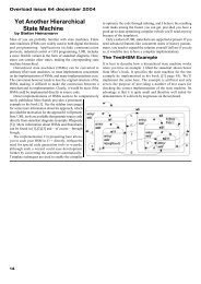
112233445566Figure A-1. <strong>LM3S811</strong> Microcontroller (sheet 1 of 3)U1U2NCPA0/U0Rx 1729 PB0/PWM2PA0/U0RxPB0/PWM2GNDVSSPA1/U0Tx 1830 PB1/PWM3PA1/U0TxPB1/PWM3+3.3VTEST5PA2/SSIClk 1933 PB2/I2CSCLPA2/SSIClkPB2/I2CSCLTEST4PA3/SSIFss 2034 PB3/I2CSDAPA3/SSIFssPB3/I2CSDATEST3+3.3VPA4/SSIRx 2144 PB4/C0-PA4/SSIRxPB4/C0-R2TEST2PA5/SSITx 2243 PB5/CCP5A PA5/SSITxPB5/CCP510KTEST142 PB6/C0+AR1PB6/C0+NC41PB710KPB7/TRSTNC+3.3V 10NC4025 PD0/PWM011TCKPC0/TCK/SWCLKPD0/PWM0VDD3926 PD1/PWM112TMS_SWDIOPC1/TMS/SWDIOPD1/PWM1BS1R63827 PD2/U1Rx13TDIPC2/TDIPD2/U1Rx+3.3V +3.3VBS23728 PD3/U1Tx14Eval Reset Switch 27TDO_SWOPC3/TDO/SWOPD3/U1TxNCPC4 1445 PD4/CCP015PC4PD4/CCP0CSnSW1PC5/CCP1 1346 PD5/CCP2PC5/CCP1PD5/CCP2R3 R4RESETn16RESnSW-PBPC6/CCP3 1247 PD6/FaultPC6/CCP3PD6/Fault2.2K 2.2K17D/CnPC7/CCP4 1148 PD7/C0O18PC7/CCP4PD7JP1WRn19PB2/I2CSCLRDnPE0/PWM4 3520PE0/PWM4D0PE1/PWM5 36JP221PE1/PWM5D1PB3/I2CSDA22D223D3ADC024ADC0D4D4ADC125ADC1D5ADC226USBRSTnADC2GNDD6ADC327ADC3R5D7MBR052028IREFOSC0+10VOSC01M 29VCOMH1030OSC1VCC31B R38NCRESETnLDOBEXTDBGENnRSTLDO27Y1JP3C22C11 2+3.3VOLED-RIT-96X16GNDVDDPA0/U0Rx+3.3V1615VCP_RX1UF .01UFGNDVDD6.00MHz2423JP4GNDVDD3132PA1/U0TxGNDVDDVCP_TX R7C30C2 C3C44.7KGND GNDC5 C6 C7 C8 C9 C100.1UF0.01UF 18PF18PF<strong>LM3S811</strong>JP50.1UF 0.1UF 0.1UF 0.1UF 0.1UF 1UF ADC0R950K Thumbwheel PotentiometerGND+3.3VHistoryPeripheral Devices+5VRevision Date DescriptionR8JP610KRemove JP1..8 (0603 Resistors) to0 Aug 2, 06 Release for Rev 0 PCBPC4A Aug 18, 06 Release for Rev A PCB, First Production Releasefree GPIO lines as required.Pin 1 is OmittedB Feb 2, 07 Add 5V break-out pad.for PolarizationADC3C40PC7/CCP4ADC2SW2CC Jul 17, 09 New RIT display, supports Serial Wire Out (SWO)39PB5/CCP5ADC1SW-PB User Push Button38PD6/FaultADC037PC4GND36PA0/U0RxPD4/CCP035PA1/U0TxPC5/CCP134PA2/SSIClkPD5/CCP2JP733PA3/SSIFssPC6/CCP3PC5/CCP1R1032PA4/SSIRxGND1031220PA5/SSITxPD7/C0O1130PD1/PWM1PB4/C0-D11229PD0/PWM0PB6/C0+Green Status LED1328GNDPB71427PD2/U1RxPE0/PWM41526PD3/U1TxPE1/PWM51625PB0/PWM2PB3/I2CSDAJP81724PB1/PWM3PB2/I2CSCLPD7/C0O1823OLEDPWRENGNDRESETn1922+3.3VGND2021TI AEC - Austin108 Wild Basin Rd.Suite 350Austin, TX 78746I/O Breakout HeadersD Designer:Drawing Title:DDAY<strong>LM3S811</strong> <strong>Evaluation</strong> <strong>Board</strong>Drawn by:Page Title:DAYMCU, Peripherals and I/O BreakoutApproved:Size Document Number: Rev* BBD-LMWLVCSheet Date: of 8/4/2009 1 312349586712345678912345678928 January 6, 2010
112233445566<strong>Stellaris</strong>® <strong>LM3S811</strong> <strong>Evaluation</strong> <strong>Board</strong>Figure A-2. <strong>LM3S811</strong> Microcontroller (sheet 2 of 3)+3.3VJ42 USB_MINI_B_RECEPTACLE98 5V D- D+ ID G+5VR36 R14 R15 R1610K 10K 10K 10K1234A C18U3AFB1VBUS0.1UF24120ohm @ 100 MHzADBUS0FT_SK233V3OUTADBUS1FT_DO22FB2ADBUS2FT_DI21FT_CS120ohm @ 100 MHzUSBM R17 ADBUS327UDM20USBDMADBUS419 DBGRSTnUSBP R18 ADBUS527 UDP17USBDPADBUS6DBGENn16ADBUS7DBGMOD15 VSENSER19ACBUS013ACBUS110K+5V+5VR20121.5KACBUS211ACBUS310R21SI/WUAVCP_RX10K40 VCP_RXR22BDBUS039 VCP_TX_SWO10KBDBUS1VCP_TX_SWO38BDBUS237EXTDBGENnBDBUS3U436BDBUS4SWO_ENJ41EECS4835VCC CSEECSBDBUS52019EESK33NC SKEESKBDBUS61817B EEDATA32ORG DIEEDATABDBUS71615BSRSTnR2347GND DOTEST1413 TDO2.2K30XTDO_SWOBCBUS01211CAT93C464329XTINBCBUS110TCK1K 64X164428XTCKXTOUTBCBUS2TMS27XTMS_SWDIOBCBUS3TDI26XTDISI/WUBRESET#41RSTOUT#PWREN#Y22X10 HDR-SHRD+3.3V+5V1 2JTAG/SWDUSB +5V to +3.3V 400mA Power SupplyC C+5VTPS73633DBV+3.3VUSBRSTnVIN SW 1Power LEDR30D C131.0MDrawing Title:DD310PFC14<strong>LM3S811</strong> <strong>Evaluation</strong> <strong>Board</strong>OLEDPWRENEN FBC15 C16Page Title:4.7UF R111UF 1UF10KR31USB and Debugger Interfaces140KSize Document Number: RevBCBD-LMWLVSheet Date: of 8/3/2009 2 3678642975311356.00MHzC19C2018PF18PF18253445GNDVCCGNDVCCGNDVCCIOAGNDVCCIOBAGNDAVCC421431C21 C23 C24 C2546R244700.1UF 0.1UF 0.1UF 0.1UFC26FT22320.1UFIN OUTC111UFEN NRC121UF12 11R25SRSTn27U5DSN74LVC125A+10V 10mA Switching Regulator87651234687124593GNDC1710nFGND+3.3VR12220+5VL14.7uHVLF4012A-4R7U7TPS61041DBVD2MBR0520+10V5432GNDJanuary 6, 2010 29
112233445566Figure A-3. <strong>LM3S811</strong> Microcontroller (sheet 3 of 3)FT_SKFT_DOTCKA 12 11R26AXTCK27U6D2 3DBGMODSN74LVC125ATDIU5AR27+3.3VSN74LVC125A10K9 8DBGENnR2910KU5CSN74LVC125A5 6U5BSN74LVC125AFT_CSU9AB BSN74LVC126A142 3U6ASN74LVC125AFT_DI+3.3VC CVCP_TX_SWOSWO_ENU6CD Drawing Title:DSN74LVC125A<strong>LM3S811</strong> Evlauation <strong>Board</strong>Page Title:Debugger MultiplexerSizeBDocument Number: RevCBD-LMWLVSheet Date: of 8/3/2009 3 3891077714113U5EVCC SN74LVC125AGNDU6EVCC SN74LVC125AGND65414110R28XTDI27TMS_SWDIO2 3R32XTMS_SWDIO27R3310K5 6+3.3V4U9BSN74LVC126ATDO_SWOU9EVCC SN74LVC126AGND0.1UF 0.1UF 0.1UFU6BSN74LVC125A8910U9CSN74LVC126A1314R35XTDO_SWO27C27C28C291112U9DSN74LVC126AVCP_TX30 January 6, 2010
A P P E N D I X BConnection DetailsThis appendix contains the following sections:• Component Locations• <strong>Evaluation</strong> <strong>Board</strong> Dimensions• I/O Breakout Pads and Recommended Connectors• ARM Target PinoutComponent LocationsFigure B-1.Component LocationsJanuary 6, 2010 31
<strong>Evaluation</strong> <strong>Board</strong> Dimensions<strong>Evaluation</strong> <strong>Board</strong> DimensionsFigure B-2.<strong>Evaluation</strong> <strong>Board</strong> DimensionsI/O Breakout Pads and Recommended ConnectorsThe <strong>LM3S811</strong> EVB has 32 I/O pads, 6 power pads, and a reset signal, for a total of 39 pads.Connection can be made by soldering wires directly to these pads, or by using 0.1” pitch headersand sockets.Table B-1. I/O Breakout PadsPad No. Description Pad No. Description1 BLANK 40 ADC32 PC7/CCP4 39 ADC23 PB5/CCP5 38 ADC14 PD6/Fault 37 ADC0 a5 PC4 a 36 GND6 PA0/U0Rx a 35 PD4/CCP07 PA1/U0Tx a 34 PC5/CCP18 PA2/SSIClk 33 PD5/CCP29 PA3/SSIFss 32 PC6/CCP310 PA4/SSIRx 31 GND11 PA5/SSITx 30 PD7/C0O a12 PD1/PWM1 29 PB4/C0-32 January 6, 2010
<strong>Stellaris</strong>® <strong>LM3S811</strong> <strong>Evaluation</strong> <strong>Board</strong>Table B-1. I/O Breakout Pads (Continued)Pad No. Description Pad No. Description13 PD0/PWM0 28 PB6/C0+14 GND 27 PB7 b15 PD2/U1Rx 26 PE0/PWM416 PD3/U1Tx 25 PE1/PWM517 PB0/PWM2 24 PB3/I2CSDA a18 PB1/PWM3 23 PB2/I2CSCL a19 GND 22 RESET20 +3.3V 21 GNDa. Indicates an I/O line that is used by EVB hardware.b. PB7 should not be used as a GPIO.Table B-2. Recommended ConnectorsPins 2-20 (19 way) Socket Sullins PPPC191LFBN-RC Digikey S7052-NDPin Header Sullins PTC19SAAN Digikey S1012-19-NDPins 21-40 (20 way) Socket Sullins PPPC201LFBN-RC Digikey S7053-NDPin Header Sullins PTC20SAAN Digikey S1012-20-NDJanuary 6, 2010 33
ARM Target PinoutARM Target PinoutIn ICDI mode, the <strong>Stellaris</strong> <strong>LM3S811</strong> <strong>Evaluation</strong> Kit supports ARM’s standard 20-pin JTAG/SWDconfiguration. The same pin configuration can be used for debugging over Serial Wire Debug(SWD) and JTAG interfaces. The debugger software, running on the PC, determines whichinterface protocol is used.The <strong>Stellaris</strong> target board should have a 2x10 0.1” pin header with signals as indicated inTable B-3.Table B-3. 20-Pin JTAG/SWD ConfigurationFunction Pin Pin Functionnc 1 2 ncnc 3 4 GNDTDI 5 6 GNDTMS 7 8 GNDTCK 9 10 GNDnc 11 12 GNDTDO 13 14 GNDRST 15 16 GNDnc 17 18 GNDnc 19 20 GNDICDI does not control the TRST (test reset) signal. This reset function is implemented as acommand over JTAG/SWD, so this signal is not necessary.34 January 6, 2010
IMPORTANT NOTICE<strong>Texas</strong> <strong>Instruments</strong> Incorporated and its subsidiaries (TI) reserve the right to make corrections, modifications, enhancements, improvements,and other changes to its products and services at any time and to discontinue any product or service without notice. Customers shouldobtain the latest relevant information before placing orders and should verify that such information is current and complete. All products aresold subject to TI’s terms and conditions of sale supplied at the time of order acknowledgment.TI warrants performance of its hardware products to the specifications applicable at the time of sale in accordance with TI’s standardwarranty. Testing and other quality control techniques are used to the extent TI deems necessary to support this warranty. Except wheremandated by government requirements, testing of all parameters of each product is not necessarily performed.TI assumes no liability for applications assistance or customer product design. Customers are responsible for their products andapplications using TI components. To minimize the risks associated with customer products and applications, customers should provideadequate design and operating safeguards.TI does not warrant or represent that any license, either express or implied, is granted under any TI patent right, copyright, mask work right,or other TI intellectual property right relating to any combination, machine, or process in which TI products or services are used. Informationpublished by TI regarding third-party products or services does not constitute a license from TI to use such products or services or awarranty or endorsement thereof. Use of such information may require a license from a third party under the patents or other intellectualproperty of the third party, or a license from TI under the patents or other intellectual property of TI.Reproduction of TI information in TI data books or data sheets is permissible only if reproduction is without alteration and is accompaniedby all associated warranties, conditions, limitations, and notices. Reproduction of this information with alteration is an unfair and deceptivebusiness practice. TI is not responsible or liable for such altered documentation. Information of third parties may be subject to additionalrestrictions.Resale of TI products or services with statements different from or beyond the parameters stated by TI for that product or service voids allexpress and any implied warranties for the associated TI product or service and is an unfair and deceptive business practice. TI is notresponsible or liable for any such statements.TI products are not authorized for use in safety-critical applications (such as life support) where a failure of the TI product would reasonablybe expected to cause severe personal injury or death, unless officers of the parties have executed an agreement specifically governingsuch use. Buyers represent that they have all necessary expertise in the safety and regulatory ramifications of their applications, andacknowledge and agree that they are solely responsible for all legal, regulatory and safety-related requirements concerning their productsand any use of TI products in such safety-critical applications, notwithstanding any applications-related information or support that may beprovided by TI. Further, Buyers must fully indemnify TI and its representatives against any damages arising out of the use of TI products insuch safety-critical applications.TI products are neither designed nor intended for use in military/aerospace applications or environments unless the TI products arespecifically designated by TI as military-grade or "enhanced plastic." Only products designated by TI as military-grade meet militaryspecifications. Buyers acknowledge and agree that any such use of TI products which TI has not designated as military-grade is solely atthe Buyer's risk, and that they are solely responsible for compliance with all legal and regulatory requirements in connection with such use.TI products are neither designed nor intended for use in automotive applications or environments unless the specific TI products aredesignated by TI as compliant with ISO/TS 16949 requirements. Buyers acknowledge and agree that, if they use any non-designatedproducts in automotive applications, TI will not be responsible for any failure to meet such requirements.Following are URLs where you can obtain information on other <strong>Texas</strong> <strong>Instruments</strong> products and application solutions:ProductsApplicationsAmplifiers amplifier.ti.com Audio www.ti.com/audioData Converters dataconverter.ti.com Automotive www.ti.com/automotiveDLP® Products www.dlp.com Communications and www.ti.com/communicationsTelecomDSP dsp.ti.com Computers and www.ti.com/computersPeripheralsClocks and Timers www.ti.com/clocks Consumer Electronics www.ti.com/consumer-appsInterface interface.ti.com Energy www.ti.com/energyLogic logic.ti.com Industrial www.ti.com/industrialPower Mgmt power.ti.com Medical www.ti.com/medicalMicrocontrollers microcontroller.ti.com Security www.ti.com/securityRFID www.ti-rfid.com Space, Avionics & www.ti.com/space-avionics-defenseDefenseRF/IF and ZigBee® Solutions www.ti.com/lprf Video and Imaging www.ti.com/videoWirelesswww.ti.com/wireless-appsMailing Address: <strong>Texas</strong> <strong>Instruments</strong>, Post Office Box 655303, Dallas, <strong>Texas</strong> 75265Copyright © 2010, <strong>Texas</strong> <strong>Instruments</strong> Incorporated