Product Note 3.106 Re: Standard Pipe Perforations (4″-60″ N-12 ...
Product Note 3.106 Re: Standard Pipe Perforations (4″-60″ N-12 ...
Product Note 3.106 Re: Standard Pipe Perforations (4″-60″ N-12 ...

Create successful ePaper yourself
Turn your PDF publications into a flip-book with our unique Google optimized e-Paper software.
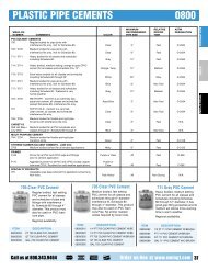
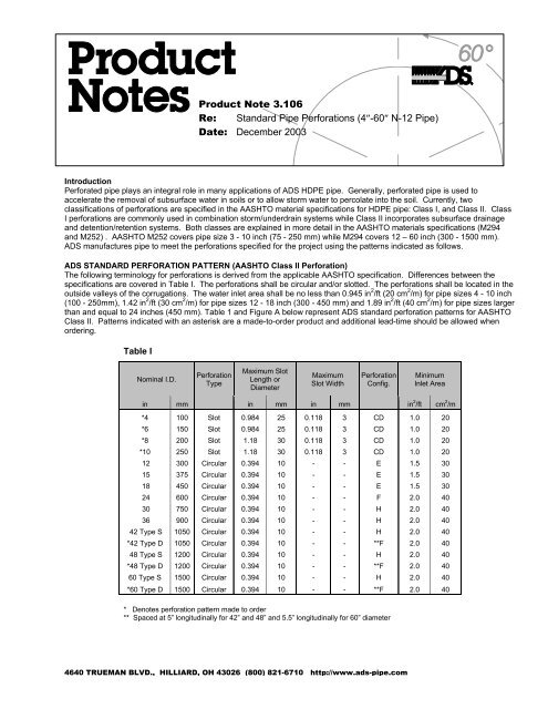
<strong>Product</strong> <strong>Note</strong> <strong>3.106</strong><strong>Re</strong>: <strong>Standard</strong> <strong>Pipe</strong> <strong>Perforations</strong> (4″-60″ N-<strong>12</strong> <strong>Pipe</strong>)Date: December 2003IntroductionPerforated pipe plays an integral role in many applications of ADS HDPE pipe. Generally, perforated pipe is used toaccelerate the removal of subsurface water in soils or to allow storm water to percolate into the soil. Currently, twoclassifications of perforations are specified in the AASHTO material specifications for HDPE pipe: Class I, and Class II. ClassI perforations are commonly used in combination storm/underdrain systems while Class II incorporates subsurface drainageand detention/retention systems. Both classes are explained in more detail in the AASHTO materials specifications (M294and M252) . AASHTO M252 covers pipe size 3 - 10 inch (75 - 250 mm) while M294 covers <strong>12</strong> – 60 inch (300 - 1500 mm).ADS manufactures pipe to meet the perforations specified for the project using the patterns indicated as follows.ADS STANDARD PERFORATION PATTERN (AASHTO Class II Perforation)The following terminology for perforations is derived from the applicable AASHTO specification. Differences between thespecifications are covered in Table I. The perforations shall be circular and/or slotted. The perforations shall be located in theoutside valleys of the corrugations. The water inlet area shall be no less than 0.945 in 2 /ft (20 cm 2 /m) for pipe sizes 4 - 10 inch(100 - 250mm), 1.42 in 2 /ft (30 cm 2 /m) for pipe sizes <strong>12</strong> - 18 inch (300 - 450 mm) and 1.89 in 2 /ft (40 cm 2 /m) for pipe sizes largerthan and equal to 24 inches (450 mm). Table 1 and Figure A below represent ADS standard perforation patterns for AASHTOClass II. Patterns indicated with an asterisk are a made-to-order product and additional lead-time should be allowed whenordering.Table INominal I.D.PerforationTypeMaximum SlotLength orDiameterMaximumSlot WidthPerforationConfig.MinimumInlet Areain mm in mm in mm in 2 /ft cm 2 /m*4 100 Slot 0.984 25 0.118 3 CD 1.0 20*6 150 Slot 0.984 25 0.118 3 CD 1.0 20*8 200 Slot 1.18 30 0.118 3 CD 1.0 20*10 250 Slot 1.18 30 0.118 3 CD 1.0 20<strong>12</strong> 300 Circular 0.394 10 - - E 1.5 3015 375 Circular 0.394 10 - - E 1.5 3018 450 Circular 0.394 10 - - E 1.5 3024 600 Circular 0.394 10 - - F 2.0 4030 750 Circular 0.394 10 - - H 2.0 4036 900 Circular 0.394 10 - - H 2.0 4042 Type S 1050 Circular 0.394 10 - - H 2.0 40*42 Type D 1050 Circular 0.394 10 - - **F 2.0 4048 Type S <strong>12</strong>00 Circular 0.394 10 - - H 2.0 40*48 Type D <strong>12</strong>00 Circular 0.394 10 - - **F 2.0 4060 Type S 1500 Circular 0.394 10 - - H 2.0 40*60 Type D 1500 Circular 0.394 10 - - **F 2.0 40* Denotes perforation pattern made to order** Spaced at 5” longitudinally for 42” and 48” and 5.5” longitudinally for 60” diameter4640 TRUEMAN BLVD., HILLIARD, OH 43026 (800) 821-6710 http://www.ads-pipe.com
Figure A – Class II Perforation Configurations
AASHTO Class I <strong>Perforations</strong>The following terminology is derived from the applicable AASHTO specification. ADS manufactures <strong>12</strong> - 24 inch (300 – 600mm) Class I perforation as a standard product (ADS designation ‘C’ perforation). However, other sizes may be ordered as amade-to-order, with sufficient lead time. Please contact your local ADS representative when ordering 4" – 10" and 30" – 60"Class 1 perforated pipe. The perforations shall be approximately circular and arranged in rows parallel to the axis of the pipe.The locations of the perforations shall be in the valley of the outside corrugation and also in each corrugation. Theperforations shall be arranged in two equal groups placed symmetrically on either side of the lower half of the pipe. Pleasenote that certain perforation patterns are not available in various parts of the United States. Please contact your local ADSrepresentative for availability and ordering of Class I perforations.TABLE IINominal I.D.inmmMin. No. ofRowsof<strong>Perforations</strong>MaximumPerforation HoleDiameterMinimumPerforation HoleDiameter“H” Maximum“L” MinimumNominalInletAreain mm in mm in mm mm mm in 2 /ft cm 2 /m<strong>12</strong> 300 06 0.40 10 0.20 5 05.4 138 07.6 192 2.65 5615 375 06 0.40 10 0.20 5 07.2 184 10.1 256 1.97 4218 450 06 0.40 10 0.20 5 08.1 207 11.3 288 1.90 4024 600 08 0.40 10 0.20 5 10.9 276 15.1 384 2.15 46*30* 750 08 0.40 10 0.20 5 13.6 345 18.9 480 1.65 35*36* 900 08 0.40 10 0.20 5 16.3 414 22.7 576 1.32 28*42 Type S 1050 08 0.40 10 0.20 5 19.0 483 26.5 672 1.31 28*42 Type D 1050 0**8** 0.40 10 0.20 5 19.0 483 26.5 672 1.36 29*48 Type S <strong>12</strong>00 08 0.40 10 0.20 5 21.7 552 30.2 768 1.29 27*48 Type D <strong>12</strong>00 0**8** 0.40 10 0.20 5 21.7 552 30.2 768 1.36 29*60 Type S 1500 <strong>12</strong> 0.40 10 0.20 5 27.2 690 37.8 960 1.70 36*60 Type D 1500 0**8** 0.40 10 0.20 5 27.2 690 37.8 960 1.85 39* Denotes perforation pattern made to order** Spaced at 5" longitudinally for 42" and 48" and 5.5" longitudinally for 60" diameterFigure B – Class I <strong>Re</strong>quirements for <strong>Perforations</strong>