cc8200 manual
cc8200 manual
cc8200 manual

Create successful ePaper yourself
Turn your PDF publications into a flip-book with our unique Google optimized e-Paper software.
®RS232 protocol listing for the AR8200 (accompanies the CC8200) Documentation release V1.3Every effort has been made to make this <strong>manual</strong> correct and up to date. Due to continuous development of the product and byerror or omission anomalies may be found and these are acknowledged. This <strong>manual</strong> is protected by copyright AOR LTD 1998.No information contained in this <strong>manual</strong> may be copied or transferred by any means without the prior written consent of AOR LTD.AOR and the AOR logo are trade marks of AOR, LTD. All other trade marks and names acknowledged. E&OE.© 1998 AOR LTD. Japan.Index1 General ................................................................. 12 Supplied accessories ............................................ 13 Connection for RS232 operation .......................... 14 Use of Microsoft Terminal & Hyper Terminal ........ 25 How to send a command ...................................... 56 Command index .................................................... 57 Detailed command list ........................................... 68 AOR control software ............................................ 189 Acknowledgements ............................................... 1810 Contact details ...................................................... 18(1) GeneralThe AR8200 is designed to be connected to a computer using the optional CC8200 lead with built-in level shift conversion, this willenable computer control via the RS232 serial port of a computer. An additional piece of software will usually be required in order toaddress the computer’s serial port with the correct set of parameters. If using an IBM-PC or clone (with 80386 processor or higher)Microsoft Hyper Terminal (or WINDOWS TERMINAL on Windows 3.1x) may be used to address the computer’s serial port.In order to gain the greatest flexibility, a specialist software package is desirable. For this reason a Windows based PC package issupplied FREE on the CD-ROM accompanying the CC8200 (this may also be made available from the AOR web siteWWW.AORJA.COM).For those wishing to compile their own software (for computers other than the PC etc) or for basic terminal control, please refer tothe following command protocol.(2) Supplied AccessoriesPlease check that the following items are included in the package:CC8200 lead with built-in level shift (9-pin D type connector)CD-ROM containing protocol listing and PC softwareOneOne(3) Connection for RS232 operationThe option socket is mounted on the right hand side of the cabinet underneath the 12V d.c. input socket. The socket is protectedfrom dust by a grey rubberised case stopper which is hinged toward the front of the cabinet. Gently lift the stopper from the rearedge to reveal the D-shaped metallic socket. Be careful to keep dust and dirt from this socket and to prevent liquid entering theAR8200 via this socket. Ensure that no conductive material is allowed to short circuit the socket which may damage the receiver.&Notes: Switching the receiver On, setting of volume and adjustment of squelch cannot be achieved via the RS232 port.Computers “always” generate RF noise which may interfere with the AR8200 reception if the standard helical rubber aerial is used.To reduce the effects of noise, use of a remote aerial is highly recommended with good quality 50 OHM coaxial cable employed.The following signals are available via the option socket including detector output, mute and AGC. This pin-out assumesconnection using the AOR optional OS8200 or CC8200 leads (refer to page 117 of the English language operating <strong>manual</strong>):-REDBLACKBLUEBROWNORANGESHIELDWHITEYELLOWGREENGREYPURPLE+4.2VRXDGROUNDMUTEAGCGROUNDTXD&Note:TXD + RXD (levels to drive a level shift converter)The voltage output level to drive external RS232 isdeliberately below ‘H’ level. If connecting to anexternal I.C., you must be aware of latch status.GROUNDAUDIO OUTDETECTOR OUTGROUNDPage 1
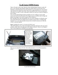
Connect the optional CC8200 computer control lead to the option socket and connect to a computer.The RS232 parameters may be defined using the CONFIG menu. Baud rates (transfer speed) maybe set to 4800, 9600 or 19200bps. It is also possible to set an ‘address’ to facilitate connection of upto 99 AR8200 to a single port for custom operation, the addresses may be set between the limits of01 to 99 with 00 representing single radio operation.When operating from external RS232, the legend ¤ will be displayed on the LCD. Please refer to page109 section 14-6 of the English language operating <strong>manual</strong> for information on the CONFIG menu settings.If your computer has a 9-pin ‘D’ type connector then simply connect to the computer’s serial port, if however the computer input is25 way, either a 9-pin male - 25-way female adaptor (ensure all pins are connected through) or patch lead will be required. If alead is used, the following connections are suggested:-CC8200 9-pin malePC 25 way female2 33 25 7 GND7 48 5The following RS232 parameters are employed:-InterfaceConnections usedFlow controlBaud rateDataParityRS232 command setBuilt in level shift within the CC8200 leadTXD, RXD, GNDSoftware X flow19200, 9600, 4800 (selectable)8 bit, 2 stop bitsNoneASCII text, or delimeter&Note: The ñòïðarrow keys and remote IDcommand (^A) are non-printableBoth the computer and AR8200 must use the same parameters for correct operation. If data is regularly lost or corrupted, try usinga slower speed such as 4800 baud. Use of a slower baud rate should not greatly reduce overall communications transfer ratesince the processing time within the receiver as PLL lock-time ultimately restricts the whole process.&Note: When changing BAUD rate, switch the AR8200 Off/On to ensure the new speed is selected.(4) Use of Microsoft WINDOWS ‘Terminal’ and ‘HyperTerminal’Windows 3.1x uses TERMINAL in a similar way using TERMINAL in the program Manager group. If the terminal program has notbeen configured an error message will appear (depending upon the serial port / mouse configuration). Click on [OK] to continue.TERMINAL will open and appear on the screen. You may re-size or maximise the screen at this point. Click on the Settingsheading toward the top of the screen so that the communications and terminal parameters may be configured. Click on“TERMINAL EMULATION” then select “ANSI” then click on [OK]. Click on the Settings heading toward the top of the screen so thatthe communications and terminal parameters may be re-configured. Click on “TERMINAL PREFERENCES” then select therequired options. Finally click on [OK]. Click on the Settings heading toward the top of the screen so that the communications andterminal parameters may be re-configured. Click on “COMMUNICATIONS” then select the options as required. The choice of COMport (COM1, COM2 etc) will depend upon your computer serial port and mouse configuration. Finally click on [OK]. Click on theFile heading toward the top of the screen and select SAVE_AS. This will enable the chosen parameters to be saved in a file whichmay be OPENED next time TERMINAL is selected so that the parameters will not require future re-configuration (.TRM being thedefault extension). The file is saved in the main WINDOWS sub directory. For further information regarding WINDOWSTERMINAL and configuration, please refer to the operating <strong>manual</strong> supplied with Microsoft software and the computer. Click on“COMMUNICATIONS” then select the required options. The choice of COM port (COM1, COM2 etc) will depend upon yourcomputer serial port and mouse configuration. Finally click on [OK].Assuming you have Windows98 loaded on an IBM-PC compatible computer (Windows95 setup is virtually identical) click on theSTART button:Next scroll up through PROGRAMS, ACCESSORIES, COMMUNICATIONS and onto HYPER TERMINAL (click):Page 2
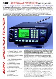
The following screen will be displayed:Double click the HYPERTRM.EXE icon, the following screen will be displayed (this may take quite a few seconds as Windowschecks your hardware:Enter an identifying name, such as AR8200 then click on OK. The CONNECT TO screen will be displayed:Select the required communications port (serial port). By default, Com1 is selected, this is correct for most lap-top computers butCom2 is more usual for a desktop computer (especially when a serial mouse is used on Com1). Click on OK.Page 3
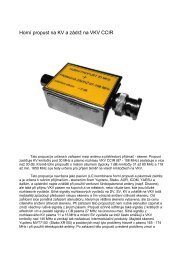
Input the required communication parameters as shown above (this example shown 9600 baud but you can select 4800 or19200), whichever has been configured on in the AR8200 receiver... they MUST be the same. Click on OK.Select the ‘PROPERTIES’ icon (finger pointing at a written page), select ‘SETTINGS’ then click on ‘ACSII Setup’.Click on the fields indicated to add carriage returns to outgoing and incoming text. Echo displays your keyboard strokes input onto the computer screen. If incoming text is double-spaced, remove the tick box for ‘ASCII Receiving’. Click OK.Refer to the command listings later in this section... to try out the link, ensure that the AR8200 is in 2VFO mode (if not type VA[ENTER] ) then type the command RX [ENTER] via the computer keyboard. The AR8200 should respond with the currentfrequency displayed on the AR8200. To change frequency type RF123 [ENTER], the AR8200 should change to 123.000 MHz.Page 4
(5) How to send a commandEach command comprises of two upper case letters (header) along with options as required. All commands use ASCII code whichMUST BE IN UPPER CASE (except for the ñòïð arrow keys and remote ID command (^A) which are non-printable and use thecontrol codes of ASCII).A multiple command entry is only valid where specified. Where a multiple command entry is allowed, each command MUST beseparated with a space “h20” (HEX DECIMAL). Each command is completed with a [CR] or [CR] [LF]. Although there is no localecho, either [CR] or specified response should come back from the receiver after confirming the correct command.If no response has been gained after a short while, the receiver has failed to receive the command properly. Send a [CR] thenre-send the command. Should problems persist, check your connections and try reducing the RS232 baud rate.AR8200 remote indicationWhen the AR8200 has received a command via the RS232C port the receiver’s LCD will display the ž symbol. The AR8200 willappear frozen while RS232 operation is in progress. To return operation to the radio keyboard,on the AR8200.(6) Command index^A Remote IDAF Automatic Frequency ControlAM Bandscope analyserAP Auto power offAS Search auto storeAT AttenuatorAU Auto modeBM Scan bank linkingBP Search bank protectBS Search bank linkingCF Bandscope centre frequencyCN CTCSS operationDA Dial (VFO) audio squelchDB Dial (VFO) level squelchDC Bandscope date centre frequencyDD Dial (VFO) delayDP Dial (VFO) pauseDS Bandscope ****DT Display frequency (on/off)EX Exit RS232GA Select scanGD Release select scan channelsGM Scan parameter selectionGR Select scan recallGS Search parameter selectionGV VFO status listLB LCD contrastLC Frequency & level statusLM Signal meter readingLS Tone eliminator frequency(requires optional TE8200 slot card)MA List a block of memory channelsMC Monitor control (forced squelch)MD Receive modeMF Bandscope set marker frequencyMP Set memory channel passMQ Delete memory channel or bankMR Memory recallMS Scan modeMW Memory bank resizingMX Memory writeNL Noise limiterOF Frequency offsetOL Set and list frequency offsetOM Opening messagePA Power savePC Protect memory channelPD Delete pass frequencyPH Bandscope peak holdPI Power save intervalPP Priority channelPQ Wait time for LC2PR List pass frequenciesPW Write search pass frequencyQM Quick memoryQP Power offQS Delete search bankRF Set receive frequencyRX Respond with current dataSA Search audio squelchSB Search level squelchSC Voice invertor frequency(requires the optional VI8200 slot card)SD Search hold / delay timeSE Set search dataSH Set offset stepSI Voice invertor on/off(requires the optional VI8200 slot card)SL Lower search frequency limitSM Start select scanSP Search pause timeSR Recall search parametersSS Start searchST Tuning step sizeSU Upper search frequency limitSW Bandscope span widthTB Set text description for bankTI Set priority intervalTM Memory textTS Text searchTT Search bank textVA Set VFO AVB Set VFO BVF Select 1-VFO modeVL Beep volumeVR Firmware versionVS VFO searchVT VFO auto-storeVV VFO scanWM Write protect bankWP Write protect enableXA Scan audio squelchXB Scan level squelchXD Memory scan delay timeXM Mode scanXP Scan pause settingUP/DOWNTuning arrowsPage 5
(7) Detailed command listing for the AR8200^A Remote ID Hex value 0x01Accepts a value nn in the range 01-99AF AFC To set: AFnn=0 (off), n=1 (on)To read: AFResponse is AFnNote: Not valid in WFM, USB, LSB or CWAM Bandscope Analyser Mode AM starts bandscope modeAM repeated when in bandscope mode generates a reportin the following format:AM PH0 CF0091000000 MF0091000000 SW1AP Auto Power off APnnnn=00 (off)nn=05-95 (sets 0.5 - 9.5 hours to power off following last active transmission)To read: APResponds with APn.n (where n.n is the delay time in hours or 0.0 = off)Note: nn must be in multiples of 0.5 hoursAS Search auto-store on/off To set: ASnn=0 (off),n=1 (on - write frequency into bank J),n=2 (on - same as 1 but erase previous channels to create spacefor new entries),To read: ASResponse is either n=0 (off) or n=1 (on)Note: Stores into the search group nominated by GSAT Attenuator To set: ATnn=0 (off),n=1 (on)To read: ATResponse is ATn, where n=0 (off) or 1 (on)AU Auto mode To set: AUnn=0 (off), n=1 (on)To read: AUResponse is AUn MDmBM Scan bank link setting To read: BMResponds with: BM nnnnnnnnnnnnnnnnnnnn,where n = character corresponding to linked bank (A - J or a - j), or - (not linked)Example: BM-BCD---------------- indicates that banks B, C & D are linkedTo set: BM nnnnnnnnnnnnnnnnnnnnWhere n is a character which specifies a bank which will have its link statustoggled (A - J or a - j). There is no need to enter a “-” to avoid changing abank linkBM%% clears all link settingsBM%% nnnnnnnnnnnnnnnnnnnn clears all links except those specifiedExamples: BM abc toggles the link status for banks a, b & cBM%% bc clears the link status for all banks except b & cNote: As defined by GM.BP Search Bank Protect To set: BPnn=0 (off), n=1 (on)To read: BPResponse is BNnBS Bank link search To read: BSResponds with: BS nnn...n, where n = character corresponding to linked bank,or - (not linked). The search bank indicators range from A - T and a - t(40 search banks in all)Example: BS-BC---F-HIJ-------R--a---e--h-j----no---stIndicates that the banks shown are linked.Page 6
To set: BS nnn...nWhere n is a bank indicator in the range A-T or a-tBS%% clears all link settingsBS%%nnn...n clears all link settings except those listedExamples:BSABRabcmp toggles the link state for the banks shownBS%% BFT clears all links except for the banks B, F & TNote: As defined by GS.CF Bandscope centre frequency To read: CFResponds with CFnnnnnnnnnnTo set: CFnnnnnnnnnn or CFnn.nnnSet the bandscope centre frequency to the specified frequency(expressed in Hz or MHz depending on format)Note: Maximum resolution is 10kHz for spans 10MHz - 500kHz; maximumresolution is 2kHz for spans 200kHz-100kHz. Frequencies below 2kHz arenot accepted.CN CTCSS operation Requires CT8200 optionTo read: CNResponds with CNnn nn=0 (off), nn=01 (auto), nn=06-37(a frequency from the following table)nn freq nn freq nn freq nn freq00 off 10 136.5 20 241.8 30 177.301 auto 11 141.3 21 250.3 31 183.512 146.2 22 67.0 32 189.913 151.4 23 71.9 33 196.614 156.7 24 74.4 34 199.515 162.2 25 77.0 35 206.506 94.8 16 167.9 26 79.7 36 229.107 100.0 17 173.8 27 82.5 37 254.108 103.5 18 179.9 28 85.409 107.2 19 186.2 29 88.50A 110.9 1A 192.8 2A 91.50B 114.8 1B 203.5 2B 97.40C 118.8 1C 210.7 2C 69.40D 123.0 1D 218.1 2D 159.80E 127.3 1E 225.7 2E 165.50F 131.8 1F 233.6 2F 171.3To set: CNnn, where nn is a two digit value from the tableDA Dial (VFO) audio squelch To set: DAnnnnnn=000 - 255 (where 000=audio squelch off)To read: DAResponds with DA nnn or DA+nnn (+ = current audio squelch level >= nnn)DB Dial (VFO) level squelch To set: DBnnnnnn=000 - 255 (where 000=level squelch off)To read: DBResponds with DB nnn or DB+nnn (+ = current level >= nnn)DC Data centre Frequency To read: DCResponds with DC nnnExample: DC000Note: Valid only when bandscope is onNote: Refer to the LM commandDD Dial (VFO) delay To set: DDnnWhere nn = 00 - 99 or FF (indicating 0.0 - 99 seconds or FF=hold)To read: DDResponds with DDn.nDP Dial (VFO) pause To set: DPnnWhere nn = 00 or 01 - 60 (indicating 1 - 60 seconds or off)To read: DPResponds with DDnnPage 7
DS Data analysis (bandscope) DSResponds with wave form data from the bandscope. This is valid only when thebandscope is functioning. Data is output on completion of each sweep over thespan, data is not continuous so response will not be instantaneous.Each datum is assigned a number totalling 1024 with 16HEX.The minimum value of each datum is [2] and maximum [F] by 16HEX.[0] = not measuring, out of span (not 10MHz or 200kHz span).[1] = out of specification of receive frequency.Note: When the span has been narrowed while measuring takes place, only thenewly selected span range will be renewed with fresh data. Care must be takenwhen the marker frequency is replaced with the centre frequency.Example of data analysis response:DSDS1023 : 2222222222222222 2222222222222222DS0991 : 2223344433222222 2233322334432233DS0959 : 2223AFB722223322 2222354222222233DS0927 : 22222222248A9632 2222222498532222DS0895 : 2232222456522222 2389A64223344322DS0863 : 2222222233343222 2222442222333222~ ~ ~ ~ ~ ~ ~ ~ ~DS0095 : C862222552224652 2222235422222222DS0063 : 2238B96322255222 2233322233223332DS0031 : 23345F9654222222 3334334332222222Note: Data is always sent 32 lines at a time.ò centre frequencyDS1023 : 2222222222222483 224535AD83332142ñ centre frequencyDS0543 : 345354339AFD9633 59564323433379ADDS0511 : 8634345443369642 2532423333458423ò -10MHzDS0031 : 233459A654222222 3334334332222222Frequency is obtained from the data of the centre frequency. Even if the span isselected as 5MHz, 500kHz or 100kHz, the response is always based on 10MHzor 20kHz.When the marker is moved, the data between the centre frequency and the newmarker frequency will be renewed.Frequency data is still obtainable from the centre frequency.Note: When a centre frequency is entered, all figures (numbers) except thesweep range (upper and lower frequencies) will be void.There are 1000 pieces of data over a 10MHz span in 10kHz steps, plus 24 piecesin reserve.Note: Data is sent continuously, either buffer memory is required or high speedprocessing is required in order not to miss data.All figures are data number (marker frequency = centre frequency)Span 10MHz 5MHz 2MHz 1MHz 50kHzUpper frequency 1023 800 620 572 545Centre frequency 512 512 512 512 512Lower frequency 12 260 410 442 482Each one represents 10kHzSpan 200kHz 100kHzUpper frequency 118 92Centre frequency 64 64Lower frequency 00 29Each one represents 2kHzDT Display frequency text To set: DTnn=0 (off), n=1 (on)Note: Frequency display is blank when n=1To read: DTResponse is DTnEX Exit RS-232 EXTerminates remote operation via the RS-232 and restores normal operationfrom the radio’s front panel.Page 8
GA Select Scan on/off To set: GAnn=0 (off), n=1 (on)GD Release select scan channel To set: GDnnnn = channel (00-49)To clear all memory select scan settings, use GD%%To read: GDResponse is GDnnNote: A select scan channel number will be incremented each time select scanchannel has been released. Confirmation is via the GR commandGM Scan parameter selection/status To set: GMnTags the current memory with label n = 0 (fixed presets only) - 9 (user definable)To read: GMExample:GMGM0 XD2.0 XB 000 XA 000 XP00 XMFBM --------------------Note: Refer to individual commands for details of each field.GRRecall tagged channelsfor select scanGRLists selected channels from those available for select scan.Response is of the form:GRnn MXmnn RFnnnnnnnnnn STnnnnnn AUn MDn ATn TMxxxxxxxxxxxNote: Refer to individual commands for details of each field.GSSearch parameter selection/status To set: GSnWhere n=0 (fixed presets only) - 9 (user definable)To read: GSExample:GSGS0 SD2.0 SB 000 SA 000 SP00 AS0BS ----------------------------------------Note: Refer to individual commands for details of each field.GV VFO set list To read: GVReads current status of the VFO as a list of parametersExample:GVGV DD0.0 DB 000 DA 000 DP00 VT0Note: Refer to individual commands for details of each field.LB LCD contrast To set: LBnnnn=00 - 31To read: LBResponds with LBnnLCRespond with frequencyand level when squelch opensTo set: LCnn=0 (off), n=1 (on), n=2 (special mode)To read: LCResponds with LCnWhen active, data in the following format is returned when the squelch opens:LCnnn Vx RFnnn...norLCnnn SRx RFnnn...norLCnnn Mnxx RFnnn...nWhen inactive, the radio returns LC data indicating the end of the transmissionas follows:LC%nnn VxorLC%nnn VxorLC%nnn VxNotes:1. Receive frequency and S-meter level are output when squelch opens (rangeof nnn reported by LC is 120-220 approx but varies from set to set)2. Response is made automatically every time squelch opens or closes and isPage 9
LMRespond with S-meterreadingaffected by squelch parameters such as level and voice scan3. Special mode (LC2) enables a continuous stream of frequency data to beoutput when squelch is open. This allows shift to next frequency after apre-defined delay specified by PQ in search/scan. This also allows for highresolution spectrum analysis.4. Signal level values may be specified 000-255, but only 100-255 is used. TheAGC voltage is processed in 256 steps internally.Note: Refer to individual commands for details of each field.To read: LMResponds with a 256-level s-meter sample in hexadecimal, LMmnnn,where nnn = 128-256 and m is either “ “ (squelch open) or “%” (squelch closed)LS Tone eliminate frequency Requires TE8200 optionTo set: LSnnn (000-255) (000=off)The following mapping is used between nnn and tone frequency:Tone Freq nnn Tone Freq nnn0.4 (kHz) 0-60 2.6 (kHz) 230-2350.6 70-110 3.0 237-2401.0 160-170 3.4 240-2451.4 190-200 3.8 245-2481.8 210-220 4.2 248-2502.2 220-230To read: LSResponds with LS nnn or LS+nnn (for mute on)MAList a block of ten memorychannelsTo read: MA or MAn (n= bank A-J or a-j)Example:MAMXA00 MP0 RF0101100000 ST100000 AU0 MD0 AT0 TMMXA01 MP0 RF0460900000 ST010000 AU0 MD1 AT0 TMTest 2MXA02 MP0 RF0085900000 ST100000 AU0 MD0 AT0 TMTest 3MXA03 MP0 RF0085900000 ST020000 AU0 MD1 AT0 TMTest 4MXA04 MP0 RF0085900000 ST020000 AU0 MD6 AT0 TMTest 5MXA05 MP0 RF0085900000 ST020000 AU0 MD7 AT0 TMTest 6MXA06 MP0 RF0085900000 ST010000 AU0 MD2 AT0 TMTest 7MXA07 MP0 RF0085900000 ST001000 AU0 MD8 AT0 TMTest 8MXA08 MP0 RF0085900000 ST000050 AU0 MD4 AT0 TMTest 9MXA09 MP0 RF0085900000 ST000050 AU0 MD3 AT0 TMTest 10Note: Refer to individual commands for details of each field.MC Monitor Control To set: MCn0 normal squelch operation1 squelch forced closed2 squelch forced openMD Receive mode To set: MDn0 WFM1 NFM2 AM3 USB4 LSB5 CW6 SFM7 WAM8 NAMTo read: MDResponds with mode value as aboveMF Set Marker Frequency To read: MFResponds with MFnnnnnnnnnnTo set: MFnnnnnnnnnn or MFnn.nnnSet the bandscope marker frequency to the specified frequency(expressed in Hz or MHz depending on format)Note: Maximum resolution is 10kHz for spans 10MHz - 500kHz; maximumresolution is 2kHz for spans 200kHz-100kHzPage 10
MP Set memory channel as pass To set: MPnn = 0 (pass off), n = 1 (pass on)To read: MP (when in memory read mode)Note: Setting pass on a memory channel excludes it from scansNote: “?” is returned when not in M.RD modeMQDelete bank or memorychannelMQDeletes the current memory channel (when in memory recall mode)MQnnDeletes memory channel nnMQx%%Deletes all memory channels from bank x.Note: Responds with “?” when a memory channel is protected. Refer to PC, WMand WP commandsMR Recall memory channel MRxnn recalls memory channel nn from bank x (A-J or a-j)To read the current memory channel: MRNote: Responds with “?” if the channel is blankMS Scan mode MSStarts scan using the current memory bankMSxStarts scan using memory bank x (A-J or a-j)Note: to scan and report active frequencies, see LC commandNote: Responds with “?” if the channel is blankMW Memory Bank resizing MWxnnSets number of channels in bank x to nn (where nn=10-90)MWxResponds with the current allocation for bank x: MW x:nn y:mmExample:MWAMW A:50 a:50MW%% or MWResponds with a list of 10 allocationsExample:MW%%MW A:50 TBAAOR TestMW a:50 TBaMW B:50 TBBAOR TestMW b:50 TBbaer bandMW C:50 TBCham callMW c:50 TBcair bandMW D:50 TBDrepeaterMW d:50 TBdaer bandMW E:50 TBEMARINEchMW e:50 TBeair bandNotes:1. This feature allows the size of memory banks to be changed in size from 10 to90 channels. Note, the total number of channels allocated to each bank pair(upper and lower case) remains 100 channels (ie size of A + size of a = 100).2. It takes a significant amount of time to execute this command. Do not attemptto send another command until the radio responds with a .3. When the size of a bank is changed, any channels that are allocated from thesmaller bank to the larger are erased (ie setting bank B to 80 channels and b to20 channels, then resetting B to 30 channels will cause the last 50 channels of Bto be erased)MX Write data to memory MXxnn RFnnnnnnnnnn AUn STnnnnnn MDn ATn TMxxxxxxxxWrites data of the format shown into memory channel nn in bank xFields are separated by a space.TM permits a 12-character alphanumeric ASCII commentAutomode will be selected if any fields are skipped but MX, RF & TM cannotbe skipped. (MX cannot be sent on its own).Note: Refer to the individual commands for further detailsNote: Do not use while scanning or searching.Page 11
NL Noise Limiter To set: NLnn = 0 (off), n = 1 (on)To read: NLResponse is NLnOF Select offset frequency OFnnxSelects offset frequency at index nn (00-47, 00=off) and defines offset tobe x (+/-)OFReturns with the current offset frequency data as follows:OFmmx RF0nnnnnnn00 (where mm is the offset index value and x is + or -)Notes:1. OF can be used on its own or with MX and SE2. Allows access to a table of offset frequencies defined by OL3. Automode operation is switched off when an offset frequency is entered4. The offset frequency range is 0.1 -999.99 MHz5. Index 00 specifies offset operation off6. Indexes 20-47 are reserved for automode and cannot be alteredOL Set and list offset frequencies OLLists ten offset frequencies from the tableOLmmLists ten offset frequencies starting from index mm (00-47)Format of listing is:OLmm RF0nnnnnnn00OLmm 0nnnnnnn00Specifies the stated offset frequency for offset mmNote: See notes for OFOM Opening message To set: OMnWhere:n=0 display the standard default messagen=1 display no opening messagen=2 display a custom 48-character message defined as follows:OM2 xxx...xPA Set delay for power save mode To set: PAnnSets the power save delay time in seconds (nn = 01-99, 00=off)To read: PAResponds with PAnn (nn = current value in seconds)Note: used on conjunction with PI commandPC Protect memory channel To set: PCnn = 0 (off), n = 1 (on)PC%%Turns off protection on all channels in the current bank.To read: PCResponse is PCnNote: Use WM command to protect a bankPD Delete pass frequency PDxnnDeletes pass frequency nn (00-49) in search bank x (A-T or a-t)PDx%%Deletes all pass channels in bank x (A-T or a-t)Note: The list of pass frequencies is shifted down each time a channel is deletedPH Bandscope Peak Hold To set: PHnn = 0 (off), n = 1 (on)To read: PHResponse is PHnPISet interval time for powersave modeTo set: PInmSets interval time in seconds (n=1-9, m=0/5)Example:PI15Sets power save interval to 1.5 secondsTo read: PIResponds with PIn.n (n.n= current interval value in seconds)Note: used on conjunction with PA commandPage 12
PP Set priority channel To set: PPxnnSelects channel xnn as the priority channel,where x is a bank A-J or a-j and nn is a channel numberTo read: PPResponds with PPxnnPQ Wait time for LC2 To set: PQnnSets time nn (00-99 corresponding to 000-990 mS in steps of 10 mS)To read: PQResponds with PQnnn (000-999 mS)Note: This wait time is used as a buffer.PR List pass frequencies PRxnnLists the pass frequency stored in pass channel nn of bank x (A-T, a-t or V)PRxLists all pass frequencies for bank x (A-T, or a-t, V = VFO)PRLists all pass frequencies in the current bank (or the VFO)???Responds with:PRxnn ffffffffffWhere x = bank, nn = channel, ffffffffff = frequency (in Hz)Example:PRPRV00 0147455000PRV01 ---PW Write search pass frequency PWWrite the current frequency to the next available pass channelPWxWrite the current frequency to the next available channel inbank x (A-T, a-t or V=VFO)PWnnnnnnnnnn or PSnnnn.nnAdds the frequency nnnnnnnnnn (in Hz) or nnnn.nn (in MHz) to the nextavailable pass channelPWxnnnnnnnnnn or PSxnnnn.nnAdds the frequency nnnnnnnnnn (in Hz) or nnnn.nn (in MHz) to the nextavailable pass channel in bank xQM Quick Memo To Read: QMResponds with ten quick memory frequencies stored within the radio infor the format:QMQM0 RF0086450000QM1 RF0087310000QM2 RF0087310000QM3 RF0000950000QM4 RF0000750000QM5 RF0087320000QM6 RF0087320000QM7 RF0087320000QM8 RF0087320000QM9 RF0087320000Note: This command is read onlyQP Power Off QPTurns off power to the AR-8200Note: there is no way to turn it on again via RS-232QS Delete search bank QSxDelete search bank x=A-T or a-tRF Set frequency RFnnnnnnnnm0Tune to the specified frequency (expressed in Hz)RFnnnn.nnnnmTune to the specified frequency (expressed in MHz)m must either be ‘5’ (for 50Hz) or ‘0’. Any other digit is ignored.Note: Frequencies below 3.0MHz are specified in kHzPage 13
RX Respond with current data RXRecalls current operating parameters in the following formatsVFO modeVF RFnnnnnnnnnn STnnnnnn AUn MDn ATn2-VFO modeVx RFnnnnnnnnnn STnnnnnn AUn MDn ATnVFO search modeVS Vx RFnnnnnnnnnn STnnnnnn AUn MDn ATnVFO scan modeVV Vx RFnnnnnnnnnn STnnnnnn AUn MDn ATnMemory <strong>manual</strong> modeMR MXxnn MPn RFnnnnnnnnnn STnnnnnn AUn MDn ATn TMxxx...xScan modeMS MXxnn MPn RFnnnnnnnnnn STnnnnnn AUn MDn ATn TMxxx...xSelect scan modeSM MXxnn MPn RFnnnnnnnnnn STnnnnnn AUn MDn ATn TMxxx...xSearch modeSRx RFnnnnnnnnnn STnnnnnn AUn MDn ATn TTxxx...xNote: Refer to individual commands for details of each field.SA Search Audio To set: SAnnnnnn = 0 (audio search off), nnn = 001-255 (level value)To read: SAResponds with SA nnn or SA+nnn (current voice level >= nnn)Note: Applies to search group specified by GSNote: Search will resume when signal strength drops below pre-set level anddelay time set by SD has elapsed.SB Search level squelch To set: SBnnnnnn = 0 (level search off), nnn = 001-255 (audio search value)To read: SBResponds with SB nnn or SB+nnn (current level >= nnn)SC Change voice invertor frequency Note: Requires VI8200To Set: SCnnnWhere nnn (000-156) defines the voice inversion frequency from the followingconversion table:nnn Freq nnn Freq nnn Freq0 2.4k 37 2.8k 64 3.2k86 3.6k 102 4.0k 116 4.4k128 4.8k 138 5.2k 146 5.6k154 6.0k 156 6.15kTo Read: SCResponds with: SCnnnSDSet hold/delay time insearch modeTo set: SDnnwhere01-99 Delay in 1/10ths of a secondFF hold00 delay offTo read: SDResponds with SDn.n, as aboveNote: Writes to the search group as specified by ‘GS’, you cannot write tosearch group 0.SE Set search data SEx SLnnnnnnnnnn SUnnnnnnnnnn AUn STnnnnnn MDn ATn TTxxx...xSets search parameters for search bank x=A-T or a-tTT permits a 12-character alphanumeric ASCII comment to be specifiedParameters ST, MD, AT, TT are all optional and need only be specifiesif required.Note: Refer to the individual commands for further detailsPage 14
SH Set offset step To set: SHnnnnm0Set the tuning step size in HzTo set: SHnnn.nmSet the tuning step size in kHzSH+nnnnm0, SH+nnn.nm or SH+ turns on step adjustm is either 0 or 5To read: SHResponds with value, format: SHnnnnm0x (x=+ step adjust on)SI Voice Invertor on/off Note: Requires VI8200To Set: SInn=0 (off), n=1 (on)To read: SIResponds with SIn SCnnnExample:SI1w SC051 when the invertor value is 051Note: Refer to individual commands for details of each field.SL Lower search frequency limit See RF command for format of frequencySM Start select scan SMStarts select scan using the parameters selectedNote: Up to 100 select scan channelsSP Search pause time setting To set: SPnnwhere, nn = 01 - 99 seconds free search time, nn = 00 pause offTo read: SPReturns with SPnn (as above)Note: Applies to the search group set by ‘GS’.SR Recall search parameters SRRecalls the currently selected search bankSRxwhere x = A-T or a-tRecalls search bank xSR%%Responds with a listing of all search banks A-JResponds with:SRx SLnnnnnnnnnn SUnnnnnnnnnn STnnnnnn AUn MDn TTxxx...xorSRR ---for a blank bankNote: Refer to the individual commands for further detailsSS Start search SSStart searching using the current search bankSSxStart searching using the parameters stored in search bank x (A-T or a-t)ST Tuning step size To set: STnnnnm0Set the tuning step size in HzTo set: STnnn.nmSet the tuning step size in kHzST+nnnnm0, ST+nnn.nm or ST+ turns on step adjustTo read: STResponds with value, format: STnnnnm0x (x=+ step adjust on)SU Upper search frequency limit See RF command for format of frequencySW Bandscope Span Width To set: SWnWhere n = 1 - 7 as follows:1 10.0MHz2 5.0MHz3 2.0MHz4 1.0MHz5 500kHz6 200kHz7 100kHzTo read: SWResponds with SWn (where n has a value as above)Page 15
TB Set Text Description for Bank To set: TBnxxxxxxxxSets the text for bank n (A-J or a-j) to be the 8-character ASCII commentspecifiedTB or TB%%Responds with a complete listing of the comments for each bank in thefollowing form:TBMW A:50 TBAAOR TestMW a:50 TBaMW B:50 TBBAORMW b:50 TBbMW C:10 TBCAOR TestMW c:90 TBcMW D:50 TBDAOR TestMW d:50 TBdMW E:50 TBEMW e:50 TBeTBxResponds with the text for bank x in the following format:TBATBAAOR TestTI Set priority interval To set: TInnSets priority interval nn (01-19) in secondsTo read: TIResponds with TDnn (nn is current priority interval value expressed in seconds)TM Memory Text To write: TMxxx...xWhere xxx...x is a 12-character ASCII text commentNote: See TT command.TS Text Search TSxxx...xSearches for the specified text in a memory channelWhere xxx...x is a minimum of 2 characters and a maximum of 11 characters ofASCII text commentNote: The more characters specified the faster the searchNote: When the text search has completed, is returnedNote: When the RX command is issued with TS, the relative bank andchannel number will be shownTT Search Bank Text To set: TTxxx...xWhere xxx...x is a 12-character ASCII text commentNote: See SE commandVA/VB Set VFO A - B To set: Vxnnnnnnnnm0 (in Hz) or Vxnnnn.nnnnm (in MHz)Where: x is A or B for VFO A or B, frequency data is expressed in the formatused by the RF commandVxSelects VFO x (A or B), there is no data returned from the radioVF Select 1-VFO mode To set: VFVL Beep volume level To set: VLnWhere, n = 0 - 9 (0=off)To read: VLResponds with VLn as aboveVR Firmware Version To read: VRResponds with data of the form:VRVR0101VSVFO searchVSStarts a VFO based search with limits defined by the frequencies in VFO A & BPage 16
VT VFO auto-store To set: VTnWhere n is defined as follows:0 Off1 On, Auto-store to bank J2 On, erase bank JTo read: VTResponds with VTn as aboveNote: VT2 response is equivalent to VT1VV VFO Scan To set: VVnWhere n=0 (2-VFO mode) or n=1 (VFO scan mode)WM Write Protect Bank To set:WMxnWhere x is bank (A-J or a-j) and n=0 (protect off), n=1 (protect on)To read:WM or WM%%Responds with a listing of 10 banks starting from the last queried bank.Example:WMWM F0WM f0WM G0WM g0WM H0WM h0WM I0WM i0WM J0WM j0WP Write protect enable To set: WPnWhere n=0 (disabled) or n=1 (enabled)To read: WPResponds with WPn as aboveXA Audio scan setting To set: XAnnnWhere, nnn = 000 (audio scan off), nnn = 001-255 (audio scan value)To read: XAResponds with XA nnn or XA+nnn (if current voice level >= nnn)Note: Applies to the scan group set by ‘GM’.XB Level scan setting To set: XBnnnWhere, nnn = 0 (level scan off), nnn = 001-255 (level scan value)To read: XBResponds with XB nnn or XB+nnn (if current level >= nnn)Note: Applies to the scan group set by ‘GM’.XD Memory scan delay time To set: XDnnnn=00 (off) or nn = 01 - 99 representing 100ms increments (0.1 - 9.9s)To read: XDResponds with XDn.n as aboveXM Mode scan To set: XMn0 WFM 1 NFM2 AM 3 USB4 LSB 5 CW6 SFM 7 WFM8 NAM F All modeTo read: XMResponds with XMn as aboveXP Free scan pause setting To set: XPnn00 pause off01-99 pause time in secondsTo read: XPResponds with XPnn as abovePage 17
Up/Down Increment nwhere n is a binary byte value as followsð 0x1cï 0x1dñ 0x1eò 0x1f(8) AOR PC Windows control software & bandplan editingA dedicated PC Windows package is supplied on CD-ROM with the CC8200 lead, it is also available as a FREE download from theAOR web site WWW.AORJA.COMIt is recommended that the AOR software be used should you wish to edit the automode bandplan data. The protocol informationfor bandplan has not been included in the CC8200 command listing as errors written to the Flash-ROM could potentially causeoperational problems.IMPORTANT: When editing the bandplan, the following points must be observed:(CC8200 Essential tips you should know before editing the auto-mode)l Every offset frequency within the auto-mode data is allocated with the specific offset table number. These numbers are used forediting the auto-mode data. Therefore you are required to obtain the offset table data prior to commencing the edit. (Get fromAR8200)After starting the program,select {File} {New} {Auto Mode File},select {Edit} {Add Item} or {Modify Item},and click {Edit offset table}.Click {Get} followed by {X} to exit.Then select {Get from RX} to download the offset table data.The offset table must be renewed by pressing the {Send} in the {Edit offset table} each time the offset frequency has beendeleted/added.l The auto-mode data is an important ingredient which is vital to the CPU brain work of the AR8200! Any incorrect data whichmay have been introduced in the course of editing will affect the operation of the receiver.1. Always allocate the change-over frequencies from lower to higher in order. A change-over frequency will work as cut-off frequencyto separate the different receive mode, step size, etc used from one segment of auto-mode to another. Therefore if thechange-over frequencies have been written high and low at random the AR8200’s CPU is unable to find the change-over frequencyrequired. Unless this condition is met you are unable to edit the auto-mode data correctly.2. A change-over frequency must be divisible by the step size of both ends (must be an even number without decimal point). If notdivisible, the change-over frequency will be forced to move (migrate) in an unstable manner every time the receiver is tuned overthe change-over frequency up and down.Ignore the step-adjust frequency when the step-adjust is applied.Where non-divisible change-over frequency is unavoidable use a stop gap method as shown below:-Frequency Step size Description459.500 25 Lower change-over frequency462.475 5 Adjusted change-over frequency462.480 240 Desired change-over frequency and step size464.880 20 Adjusted change-over frequency464.900 12.5 Desired change-over frequency and step sizeSuch adjusted change-over frequencies may be found within the factory auto-mode data.3. Make sure you reset the CPU.Unplug the external power and remove a battery cell to allow the CPU to reset. This is required to force the flag within the CPU andthe contents of the flash ROM to become consistent/identical. Without the CPU reset some malfunctions may be encountered.4. Rewriting the memoryOld memory channel data such as frequency, receive mode, step size (prior to editing) may still be found valid in some memorychannels. This will cause conflict between new auto-mode data and old memory channel data. Rewrite the memory channels usingthe new auto-mode to resolve such conflict.Page 18
Installing the softwareTo install the AOR software run the INSTALL.EXE program from the CD-ROM (x:\English\CC8200\cont-soft\install.exewhere ‘x’ is your CD-ROM drive letter). If installing from a web download, expand the ZIP file into a temporary directory on yourhard drive then run the INSTALL.EXEA directory will be created on your hard drive along with a program group from the START/PROGRAMS button of the desktop.This software package will also provide additional facilities such as memory channel & search bank editing, spectrum display and arecord-to-disk sound utility.(9) AcknowledgementsThis <strong>manual</strong> has been compiled by AOR UK LTD using materials supplied by AOR Japan. The original compilation was bySimon Collings G4SGI whom we wish to thank.The software package was created for AOR LTD by Simon Collings G4SGI.Thanks to AOR LTD, AOR UK LTD, Javiation and Simon Collings for final beta-testing of the software.All trade marks acknowledged (such as Microsoft, Windows, IBM etc).Please refer to the AOR web site for updates on this file and the AR8200 Windows PC software.(10) Contact detailsAOR Ltd, 2-6-4 Misuji, Taito-Ku, Tokyo 111-0055, JapanTel: +81 3 3865 1695Fax: +81 3 3865 1697post@aorja.com www.aorja.comAOR (UK) Ltd, 4E East Mill, Bridgefoot, Belper, Derbys DE56 2UA, EnglandTel: +44 1773 880788Fax: +44 1773 880780info@aor.co.uk www.demon.co.uk/aorAOR USA, INC. 20665 S.Western Ave., Suite # 112, Torrance, CA 90501, USATel: (310) 787 8615Fax: (310) 787 8619info@aorusa.com www.aorusa.comPage 19
Thank you for purchasing the CC8200.CC8200 - AR8200 REMOTE CONTROLThis CD-ROM is supplied with the CC8200 and contains the following data in both Japanese and English languages.Should you wish to use English language, please select the files under , should you wish to use Japaneselanguage, please select the files under .CD-ROMreadme-j.txt Read me file in Japanese languagereadme-e.txt Read me file in English language (this information sheet)Regarding the AR8200 control software Adobe ® Acrobat ® Reader AR8200 bandplan data AR8200 free control software AR8200 command list in Japanese languagecatalog-j.pdf Product information in PDF format Adobe ® Acrobat ® Reader AR8200 bandplan data AR8200 free control software AR8200 command list in English languagecatalog-e.pdf Product information in PDF formatPlease ensure prior to operating the control software that you understand and accep the following conditions:-l This software is available free of charge.l Copyright and intellectual property rights are owned by AOR as the software author.l Any attempt to alter the software is subject to copyright infringement.l Any attempt to “do what the author prohibits” (refer to help) is subject to copyright infringement.l No liability is accepted for any inconvenience or damage caused by use of the software.AOR LTD holds no liability for:-l The author is not liable to correct or remedy any inconvenience or requests from the user.l No specific support is available from AOR LTD.Regarding the supply of Adobe ® Acrobat ® ReaderAdobe ® Acrobat ® Reader is available free of charge to those who need to write, read and search in PDF formatirrespective of whether within or outside of the company. Acrobat ® Reader 3.0 is available for unlimited use ordistribution provided you attach a copy of warning regarding the electronic end-user licence agreement, relatedcopyright and other ownership agreement.®AOR LTD2-6-4 MisujiTaito-KuTokyo 111-0055Japane-mail: post@aorja.comJapanese languageEnglish languageTel: 03 3865 1681 +81 3 3865 1695Fax: 03 3862 9927 +81 3 3865 1697www.aorja.com/index-j.html www.aorja.com© 1998.9.2, AOR LTD [paperwork issue 1.1]Page 20