Install & User Manual - Livewire Connections Ltd
Install & User Manual - Livewire Connections Ltd
Install & User Manual - Livewire Connections Ltd
- No tags were found...

Create successful ePaper yourself
Turn your PDF publications into a flip-book with our unique Google optimized e-Paper software.
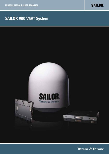
INSTALLATION & USER MANUALSAILOR 900 VSAT System
SAILOR 900 VSAT<strong>Install</strong>ation and user manualDocument number: 98-133400-FRelease date: 25 February 2013
DisclaimerAny responsibility or liability for loss or damage in connection with the use of this product and theaccompanying documentation is disclaimed by Thrane & Thrane. The information in this manual isprovided for information purposes only, is subject to change without notice and may contain errors orinaccuracies. <strong>Manual</strong>s issued by Thrane & Thrane are periodically revised and updated. Anyone relying onthis information should acquire the most current version e.g. from cobham.com/satcom or from thedistributor. Thrane & Thrane is not responsible for the content or accuracy of any translations orreproductions, in whole or in part, of this manual from any other source.Thrane & Thrane A/S trading as Cobham SATCOM.Copyright © 2013 Thrane & Thrane A/S. All rights reserved.Trademark acknowledgements• Thrane & Thrane is a registered trademark of Thrane & Thrane A/S in the European Union and theUnited States.• SAILOR is a registered trademark of Thrane & Thrane A/S in the European Union and the UnitedStates.• Windows is a registered trademark of Microsoft Corporation in the United States and othercountries.• Other product and company names mentioned in this manual may be trademarks or trade names oftheir respective owners.GPL notificationThe software included in this product contains copyrighted software that is licensed under the GPL/LGPL.The verbatim licenses can be found online at:http://www.gnu.org/licenses/old-licenses/gpl-2.0.htmlhttp://www.gnu.org/licenses/old-licenses/lgpl-2.1.htmlYou may obtain the complete corresponding source code from us for a period of three years after our lastshipment of this product, which will be no earlier than 2021, by sending a money order or check for DKK50 to:SW Technology/GPL Compliance,Cobham SATCOM,Lundtoftegaardsvej 93D2800 LyngbyDENMARKPlease write "source for product SAILOR 900 VSAT" in the memo line of your payment.You may also find a copy of the source at http://www.thrane.com/foss.This offer is valid to anyone in receipt of this information.ii98-133400-F
Safety summaryThe following general safety precautions must be observed during all phases of operation,service and repair of this equipment. Failure to comply with these precautions or with specificwarnings elsewhere in this manual violates safety standards of design, manufacture andintended use of the equipment. Cobham SATCOM assumes no liability for the customer'sfailure to comply with these requirements.Microwave radiation hazardsDuring transmission the Above Deck Unit (antenna) in thissystem radiates Microwave Power.This radiation may behazardous to humans close to the Above Deck Unit. Duringtransmission, make sure that nobody gets closer than therecommended minimum safety distance.The minimum safety distance to the Above Deck Unitreflector on the focal line is 30 m, based on a radiation levelof 10 W/m 2 . No hazard exists >25° below the Above Deck Unit’s mounting plane. Refer to thedrawing below.MICROWAVE RADIATIONNo personnel within safety distanceSafety distance:30 m, 10 W/m 2No-transmit zonesIn order to protect personnel no-transmit zones can be programmed. For further informationsee Blocking zones — azimuth and elevation on page 3-5.Distance to other equipmentDo not move the Above Deck Unit closer to radars than the minimum safe distance specified insection Interference on page 3-13 — it may cause damage to the Above Deck Unit.Compass Safe Distance:SAILOR 900 VSAT antenna or ADU (Above Deck Unit): min. 130 cm (IEC 945).SAILOR 900 VSAT ACU (Antenna Control Unit): min. 10 cm (IEC 945)98-133400-Fiii
Service<strong>User</strong> access to the interior of the ACU is prohibited. Only a technician authorized by CobhamSATCOM may perform service - failure to comply with this rule will void the warranty. Access tothe interior of the Above Deck Unit is allowed. Replacement of certain modules and generalservice may only be performed by a technician authorized by Cobham SATCOM.Grounding, cables and connectionsTo minimize shock hazard and to protect against lightning, the equipment chassis and cabinetmust be connected to an electrical ground. The ACU must be grounded to the ship. For furthergrounding information refer to the <strong>Install</strong>ation manual.Do not extend the cables beyond the lengths specified for the equipment. The cable betweenthe ACU and Above Deck Unit can be extended if it complies with the specified dataconcerning cable losses etc.Rx and Tx cables for the SAILOR 900 VSAT system are shielded and should not be affected bymagnetic fields. However, try to avoid running cables parallel to high power and AC/RF wiring asit might cause malfunction of the equipment.Power supplyThe voltage range for the SAILOR 900 VSAT is 20 — 32 VDC. Note that the Above Deck Unit ispowered by the ACU.If a 24 VDC power bus is not available, an external 115/230 VAC to 28 VDC power supply canbe used, for example a SAILOR 6080 Power Supply.Do not operate in an explosive atmosphereDo not operate the equipment in the presence of flammable gases or fumes. Operation of anyelectrical equipment in such an environment constitutes a definite safety hazard.Keep away from live circuitsOperating personnel must not remove equipment covers. Component replacement and internaladjustment must be made by qualified maintenance personnel. Do not replace componentswith the power cable connected. Under certain conditions, dangerous voltages may exist evenwith the power cable removed. To avoid injuries, always disconnect power and dischargecircuits before touching them.Failure to comply with the rules above will void the warranty!iv98-133400-F
CAUTION! Do not manually turn the Polarisation Unit of the antenna, itmay cause damage to the antenna.If needed to turn the Polarisation Unit manually, remove the connector (1) marked M of thePolarisation Motor Module (2).(1)(2)RemoveMVSAT restrictionsNoteThere are restrictions in use of the frequency band 13.75 to 14 GHz in thefollowing countries:• Belgium• Hungary• Latvia• Malta• SlovakiaContact VSAT modem provider for local setups.98-133400-Fv
Record of RevisionsRev. Description Release Date InitialsA Original document 26 September 2011 UFOB Sections added: 6.3.6, 6.3.7, 6.3.8, 9.4, Appendix B, Appendix C. -Sections edited: 1.2, 3.1.1, 3.2.6 (p. 3-10) 3.6.1, 4.1.7, 6.2.2, 6.3,9.1.1. Figures added: 6-3, A-1, A-2.Figures edited: 2-4, 2-5, 6-4, 6-5, 6-6, 6-7, 6-14, 8-1, 9-10, 9-11.Tables have been edited: 2-1, 2-2, 6-5.C Sections added: p.v (VSAT restrictions), 1.3, 3.32, App. D.Sections edited: 4.1.8, 4.1.10, 6.2.1, 6.2.2, 6.3.3, 6.3.4, 6.3.5,6.3.6, 6.3.10.Figures edited: 2-4, 6-8, 6-9, 6-11, 6-17, 9-5, 9-10.Tables added: 6-5, 6-6.Tables edited: 6-3, 6-9, F-1, F-2D Sections added: 6.2.3, App. D, App. H.Sections edited: p. v, 1.2, 1.3, 2.1.1, 4.1.8, 6.2.1, 6.3.10, 9.5.Figures added: 6-15.Figures edited: 4-5, 6-3, 6-5, 6-8, 6-9, 6-10, 6-25, 6-31, 8-1, 8-2,9-4, 9-5.Tables added: A-5, A-6.Tables edited: 4.1, 6-8, 6-13, 7-2, E-1, G-1, G-2.E Sections added: 3.7, 4.2.4, 4.2.5, 6.3.9, 6.5, C.5, D.2.2, D.2.3, F.7Sections edited: 2.1, 3.1.1, 3.1.3, 3.3.3, 5.4, 6.2.1, 6.2.2, 6.3.5,6.4.1, 9.2.2, C.1.3, F.2.1, F.3.2Figures added: 3.22, 6-17, A-4, C-13Figures edited: 6-9, 6-16, 6-21, 8-1Tables added: 6-10Tables edited: 2-2, 4-4, 6-9, 6-11, 7-2, A-4, C-4, E-1, G-1, G-28 November 2011 UFO13 January 2012 UFO11 June 2012 UFO31 October 2012 UFOFSections added: 6.2.3, 8.2.2, A.1.5, C.1.4, C.3.2, C.4.3, C.5.3, C-6,H.2Sections edited: ii,1.3, 6.2.1., 6.2.2, 6.3.1, 6.3.4, 6.5, C.1.3Figures added: 6-6, 6-12, 8-3, 8-4, 8-5, 8-6Figures edited: 3-26, 6-2, 6-3, 6-4, 6-11, 6-14, 6-16, 6-26, 8-10,C-9, C-10Tables have been added: 6-8Tables have been edited: 2-1, 2-2, 3-8, 6-2, 6-6, A-625 February 2013 UFOvi98-133400-F
Table of ContentsChapter 1Chapter 2Chapter 3About this manual1.1 Intended readers .............................................................................1-11.2 <strong>Manual</strong> overview .............................................................................1-11.3 Software version ..............................................................................1-11.4 Typography ..................................................................................... 1-21.5 Precautions ..................................................................................... 1-2Introduction2.1 SAILOR 900 VSAT system .............................................................. 2-12.1.1 Above Deck Unit (ADU) ...................................................................................................2-22.1.2 Antenna Control Unit (ACU) ..........................................................................................2-52.1.3 VSAT Modem Unit (VMU) ..............................................................................................2-72.1.4 Satellite type approvals ....................................................................................................2-72.1.5 Power supply (optional) ...................................................................................................2-72.1.6 Service activation ................................................................................................................2-72.2 Part numbers and options .............................................................2-82.2.1 Applicable Thrane & Thrane model and part numbers .....................................2-82.2.2 Options for SAILOR 900 VSAT .....................................................................................2-8<strong>Install</strong>ation3.1 Unpacking ....................................................................................... 3-13.1.1 What’s in the box ................................................................................................................3-13.1.2 Initial inspection ..................................................................................................................3-23.1.3 Tools needed .........................................................................................................................3-23.2 Site preparation ..............................................................................3-33.2.1 General site considerations ............................................................................................3-33.2.2 Obstructions (ADU shadowing) ....................................................................................3-43.2.3 Blocking zones — azimuth and elevation ...............................................................3-53.2.4 Safe access to the ADU: Radiation hazard ..............................................................3-63.2.5 Ship motion and offset from the ship’s motion centre ....................................3-73.2.6 ADU mast design: Foundation and height ..............................................................3-83.2.7 Interference ........................................................................................................................3-133.2.8 Other precautions ............................................................................................................3-1798-133400-Fix
Table of Contents3.3 <strong>Install</strong>ation of the ADU ................................................................3-183.3.1 <strong>Install</strong>ing the ADU ............................................................................................................3-193.3.2 Opening and removing the service hatch ............................................................3-223.3.3 Grounding the ADU .........................................................................................................3-233.3.4 Alternative ADU cable ...................................................................................................3-243.4 <strong>Install</strong>ation of the ACU ............................................................... 3-253.4.1 <strong>Install</strong>ing the 19” rack version of the ACU ..........................................................3-253.4.2 Grounding the ACU .........................................................................................................3-253.5 <strong>Install</strong>ation of the VMU .............................................................. 3-263.5.1 General mounting considerations — VMU .........................................................3-263.6 <strong>Install</strong>ing the dual-antenna mode (optional) ............................. 3-27Chapter 4Chapter 5Interfaces4.1 Interfaces of the SAILOR 900 VSAT ACU .....................................4-14.1.1 LEDs, display and keypad .................................................................................................4-14.1.2 ACU connector panel — overview .............................................................................4-14.1.3 DC Input connector ...........................................................................................................4-24.1.4 ADU connector ....................................................................................................................4-34.1.5 Rx/Tx connectors for VMU ......................................................................................4-34.1.6 NMEA 0183 connector (RS-422) ................................................................................4-44.1.7 RS-232 and RS-422 connectors ...................................................................................4-54.1.8 LAN1, LAN2, LAN3 and LAN4 connectors ...............................................................4-64.2 Interfaces of the VMU ................................................................... 4-74.2.1 Connecting an iNFINITI® Series Satellite Router ...............................................4-74.2.2 Connecting an Evolution® Satellite Router ...........................................................4-84.2.3 Connecting a COMTECH 570 L or 625 Satellite Modem ................................4-84.2.4 Connecting a Satlink 2900 VSAT modem ...........................................................4-104.2.5 Connecting a Gilat SkyEdge II VSAT modem ....................................................4-10Connecting power5.1 Power source ...................................................................................5-15.2 Power cable selection ....................................................................5-25.2.1 Source impedance ..............................................................................................................5-25.2.2 Measuring the ship source impedance .....................................................................5-25.2.3 Power cable recommendations ....................................................................................5-35.3 Connecting power ..........................................................................5-45.4 Power up .........................................................................................5-5x98-133400-F
Table of ContentsChapter 6Chapter 7Chapter 8Configuration6.1 Introduction to the built-in web interface .................................. 6-16.1.1 Overview ..................................................................................................................................6-16.1.2 Connecting to the web interface ................................................................................6-16.2 Calibration of the SAILOR 900 VSAT ............................................6-36.2.1 Setup of a service profile for calibration ..................................................................6-36.2.2 Vessel heading & calibration of azimuth and cable ............................................6-56.2.3 Flow chart for azimuth and cable calibration ........................................................6-96.2.4 Line up procedure ............................................................................................................6-106.2.5 SAILOR 900 VSAT fixed TX gain principle ...........................................................6-126.3 Configuration with the web interface ........................................ 6-136.3.1 Overview and dashboard ..............................................................................................6-136.3.2 Satellite profiles and VSAT modem profiles .......................................................6-196.3.3 Setting up Blocking zones (RX and TX) ..................................................................6-246.3.4 Configuring the LAN network .....................................................................................6-266.3.5 E-mail setup ........................................................................................................................6-296.3.6 Sending statistics reports .............................................................................................6-306.3.7 Sending a diagnostics report ......................................................................................6-336.3.8 Dual antenna mode (optional) ...................................................................................6-346.3.9 Upload ...................................................................................................................................6-396.3.10 Administration ...................................................................................................................6-396.4 Keypad and menus of the ACU ...................................................6-456.4.1 ACU display and keypad ...............................................................................................6-456.4.2 Navigating the menus ....................................................................................................6-466.4.3 The menu tree ...................................................................................................................6-466.4.4 Adjusting brightness of the display .........................................................................6-506.4.5 Resetting the system ......................................................................................................6-506.5 SNMP support ............................................................................... 6-51<strong>Install</strong>ation check7.1 <strong>Install</strong>ation check list: Antenna .................................................... 7-17.2 <strong>Install</strong>ation check list: ACU, connectors and wiring ....................7-37.3 <strong>Install</strong>ation check list: Functional test in harbor .........................7-5Service8.1 Getting support: Helpdesk .............................................................8-28.1.1 Help desk and diagnostic report ..................................................................................8-298-133400-Fxi
Table of Contents8.2 Software update .............................................................................8-48.2.1 Hardware and software requirements .......................................................................8-48.2.2 Software update (ADU and ACU) ................................................................................8-48.2.3 Verifying the software update ......................................................................................8-78.3 Status signalling with LEDs and status messages ........................8-88.3.1 LEDs of the ADU modules ...............................................................................................8-98.3.2 LEDs in the ACU ...................................................................................................................8-98.4 Removal and replacement of the ACU ........................................8-108.5 Removal and replacement of ADU modules ............................... 8-118.6 Troubleshooting ............................................................................8-148.6.1 Overview ...............................................................................................................................8-148.6.2 Event list for troubleshooting .....................................................................................8-148.6.3 Diagnostic report for troubleshooting ...................................................................8-14Appendix AAppendix BAppendix CTechnical specificationsA.1 SAILOR 900 VSAT system components ....................................... A-1A.1.1 General specifications ...................................................................................................... A-1A.1.2 ADU .......................................................................................................................................... A-2A.1.3 ACU ........................................................................................................................................... A-4A.1.4 Supported VSAT modems ............................................................................................. A-5A.1.5 Patents ..................................................................................................................................... A-5A.2 Outline drawings ............................................................................A-6A.2.1 ADU .......................................................................................................................................... A-6A.2.2 ACU (19 inch rack) ............................................................................................................ A-7A.2.3 N-connector interface on the ADU ........................................................................... A-8A.3 VSAT LNB Data Sheet (physical LNB) ...........................................A-9A.3.1 VSAT LNB user installation and configuration information ....................... A-10A.4 VSAT 8 W BUC Data Sheet (Extended) ....................................... A-11VMU cablesB.1 Modem Cable COMTECH Serial & RSSI TT7016A ........................B-2B.2 Modem Cable iNFINITI iDirect VSAT modem ............................B-3VMU settingsC.1 OpenAMIP setup for iDirect iNFINITI 5000 & Evolution X5 .....C-2C.1.1 Protocol and interfaces ................................................................................................... C-2C.1.2 Sample options file ............................................................................................................ C-5C.1.3 Configuration example (OpenAMIP) ........................................................................ C-7C.1.4 Troubleshooting ................................................................................................................. C-8xii98-133400-F
Table of ContentsC.2 Serial setup for iDirect iNFINITI 5000 & Evolution X5 ............. C-11C.2.1 Protocol and interfaces ................................................................................................ C-11C.2.2 Console port settings .................................................................................................... C-12C.2.3 Configuration example (Serial) ................................................................................. C-14C.3 COMTECH 570L and ROSS box .................................................... C-15C.3.1 Protocols and interfaces .............................................................................................. C-15C.3.2 Configuration example (COMTECH 570L and ROSS) .....................................C-16C.4 STM SatLink 2900 VSAT modem ................................................. C-17C.4.1 Interfaces and VSAT modem configuration ...................................................... C-17C.4.2 ACU configuration .......................................................................................................... C-18C.4.3 Configuration example (STM Satlink 2900) ....................................................... C-19C.5 Gilat SkyEdge II VSAT modem ....................................................C-20C.5.1 Interfaces and VSAT modem configuration .......................................................C-20C.5.2 ACU configuration .......................................................................................................... C-21C.5.3 Configuration example (Gilat SkyEdge II ) ......................................................... C-22C.6 Inmarsat G5 modem ....................................................................C-23C.6.1 Interfaces and VSAT modem configuration ...................................................... C-23C.6.2 Connecting a Inmarsat G5 modem ........................................................................ C-23C.6.3 Configuration example (Inmarsat G5) .................................................................. C-23Appendix DAppendix ECommand line interfaceD.1 Introduction ...................................................................................D-1D.1.1 Telnet connection ..............................................................................................................D-1D.1.2 Help ...........................................................................................................................................D-2D.1.3 Conventions ..........................................................................................................................D-2D.2 Supported commands .................................................................. D-3D.2.1 config .......................................................................................................................................D-3D.2.2 demo ........................................................................................................................................D-3D.2.3 dual_antenna ........................................................................................................................D-4D.2.4 exit .............................................................................................................................................D-4D.2.5 help ............................................................................................................................................D-4D.2.6 modem ....................................................................................................................................D-5D.2.7 satellite ....................................................................................................................................D-5D.2.8 status ........................................................................................................................................D-7D.2.9 system .....................................................................................................................................D-8D.2.10 track ..........................................................................................................................................D-8D.2.11 zone ..........................................................................................................................................D-9DVB-S satellites98-133400-Fxiii
Table of ContentsAppendix FGrounding and RF protectionF.1 Why is grounding required? ............................................................F-1F.1.1 Reasons for grounding ......................................................................................................F-1F.1.2 Safety ........................................................................................................................................F-1F.1.3 ESD Protection .....................................................................................................................F-1F.2 Grounding Recommendations ....................................................... F-2F.2.1 Grounding the ACU ............................................................................................................F-2F.2.2 Grounding the ADU ............................................................................................................F-2F.3 Alternative grounding for steel hulls ............................................F-3F.3.1 Grounding the ACU ............................................................................................................F-3F.3.2 Grounding the ADU ............................................................................................................F-4F.4 Alternative grounding for aluminum hulls ...................................F-5F.4.1 Grounding the ACU ............................................................................................................F-5F.4.2 Grounding the ADU ............................................................................................................F-5F.5 Alternative grounding for fibre glass hulls ...................................F-6F.5.1 Grounding the ACU ............................................................................................................F-6F.5.2 Grounding the ADU ............................................................................................................F-6F.6 Separate ground cable ................................................................... F-7F.6.1 Ground cable - construction ..........................................................................................F-7F.6.2 Ground cable - connection .............................................................................................F-8F.6.3 Isolation of the ADU from the mounting base .....................................................F-8F.7 Jumper cable for grounding ..........................................................F-10F.8 RF interference .............................................................................. F-11F.8.1 Recommendations ...........................................................................................................F-11Appendix GAppendix HGlossaryIndexSystem messagesG.1 Event messages – overview ........................................................... G-1G.2 List of ADU events .........................................................................G-2G.3 List of ACU events ........................................................................ G-8ApprovalsH.1 Overview ......................................................................................... H-1H.2 CE (R&TTE) ...................................................................................... H-1H.3 Eutelsat S.A – ESV Summary Sheet ............................................. H-3............................................................................................................ Glossary-1.................................................................................................................Index-1xiv98-133400-F
List of FiguresChapter 1About this manualChapter 2 IntroductionFigure 2-1: Above Deck Unit and Antenna Control Unit (ACU), 19” rack version .....................................2-1Figure 2-2: Above Deck Unit (ADU)..................................................................................................................................2-2Figure 2-3: Above Deck Unit modules 1/2 ....................................................................................................................2-3Figure 2-4: Above Deck Unit modules 2/2 ....................................................................................................................2-4Figure 2-5: SAILOR 900 VSAT ACU, connector overview .....................................................................................2-6Figure 2-6: SAILOR 900 VSAT ACU, 19” rack version..............................................................................................2-6Figure 2-7: Antenna Control Unit for 19” rack installation ...................................................................................2-7Chapter 3 <strong>Install</strong>ationFigure 3-1: Signal degradation because of obstructing objects..........................................................................3-4Figure 3-2: 2 blocking zones with no-transmit zones, azimuth (example)....................................................3-5Figure 3-3: Blocking zone with no-transmit zones, elevation angle (example)...........................................3-5Figure 3-4: Radiation hazard, safety distance 30 m .................................................................................................3-6Figure 3-5: Maximum distance from the ship’s motion centre (h max) .........................................................3-7Figure 3-6: ADU mast flange, top and side view ........................................................................................................3-8Figure 3-7: ADU mast flange, recommended flatness on the mast mount plateau..................................3-8Figure 3-8: ADU mast flange, distance to the welded seam.................................................................................3-9Figure 3-9: ADU, bottom view ............................................................................................................................................3-9Figure 3-10: Free mast length and bracing for a tall mast.....................................................................................3-10Figure 3-11: Interference with the vessel’s radar ......................................................................................................3-13Figure 3-12: Recommended distance to transmitters (m) for frequencies below 1000 MHz.............3-16Figure 3-13: Drain pipe with free space .........................................................................................................................3-17Figure 3-14: Use of strong sling with a belt and tag lines for safe hoisting..................................................3-18Figure 3-15: Free space for access to the service hatch ........................................................................................3-19Figure 3-16: ADU installation, webbed sling attached to the 4 lifting brackets .........................................3-20Figure 3-17: Mounting the ADU on the mast flange ...............................................................................................3-20Figure 3-18: Connecting the ADU cable ........................................................................................................................3-21Figure 3-19: Opening the service hatch .........................................................................................................................3-22Figure 3-20: Removing the 2 split pins ...........................................................................................................................3-22Figure 3-21: ADU, bolt for optimum grounding.........................................................................................................3-23Figure 3-22: ACU, 19” rack version, On/off switch at the back...........................................................................3-25Figure 3-23: ACU, LAN connector at the front: Service port ...............................................................................3-25Figure 3-24: ACU, 19” rack version, ground stud.......................................................................................................3-26Figure 3-25: Dual mode antenna, overview..................................................................................................................3-27Figure 3-26: Dual mode antenna, connecting cables (example)........................................................................3-2898-133400-Fxv
List of FiguresChapter 4 InterfacesFigure 4-1: ACU — LEDs, display and keypad .............................................................................................................4-1Figure 4-2: ACU: LEDs, display and keypad (detailed) .............................................................................................4-1Figure 4-3: ACU rack version, connector panel overview......................................................................................4-1Figure 4-4: DC Input connector with power cable....................................................................................................4-2Figure 4-5: LAN1 —LAN4 connectors.............................................................................................................................4-6Figure 4-6: Connecting an iNFINITI® Series Satellite Router.............................................................................4-7Figure 4-7: Connecting an Evolution Satellite Router..............................................................................................4-8Figure 4-8: Connecting a COMTECH 570 L or 625 Satellite Modem...............................................................4-8Figure 4-9: Connecting a SatLink 2900 Modem .....................................................................................................4-10Figure 4-10: Connecting a Gilat SkyEdge II VSAT Modem...................................................................................4-10Chapter 5 Connecting powerFigure 5-1: Measuring the ship source impedance ...................................................................................................5-2Figure 5-2: Connecting power to DC Input ..................................................................................................................5-4Figure 5-3: ACU display after first power on (example with LAN ports 1 and 4 used)............................5-5Chapter 6 ConfigurationFigure 6-1: LAN connector used for configuring the SAILOR 900 VSAT .......................................................6-1Figure 6-2: SAILOR 900 VSAT Dashboard.....................................................................................................................6-2Figure 6-3: Service profile for calibration ......................................................................................................................6-4Figure 6-4: Web interface: SERVICE, Calibration .......................................................................................................6-5Figure 6-5: Web interface: SERVICE, Calibration, cable attenuator margin..................................................6-7Figure 6-6: Example for azimuth and cable calibration — step by step.........................................................6-9Figure 6-7: Web interface: SERVICE, Line up: Ready for activation...............................................................6-10Figure 6-8: Web interface: SERVICE, Line up: Antenna ready...........................................................................6-11Figure 6-9: Fixed TX gain principle.................................................................................................................................6-12Figure 6-10: Topics in the web interface (SITE MAP) .............................................................................................6-13Figure 6-11: Web interface: DASHBOARD ....................................................................................................................6-14Figure 6-12: Web interface: DASHBOARD, TX - BUC output power (example)..........................................6-18Figure 6-13: Web interface: SETTINGS - list of satellite profiles (example).................................................6-19Figure 6-14: Web interface: SETTINGS, Satellite profiles — new entry (example)..................................6-20Figure 6-15: Web interface: SETTINGS, VSAT modem profiles — list (example).....................................6-22Figure 6-16: Web interface: SETTINGS, VSAT modem profile – supported modems.............................6-22Figure 6-17: Satellite profile for generic modem.......................................................................................................6-23Figure 6-18: Web interface: SETTINGS, Blocking zones — azimuth and elevation .................................6-24Figure 6-19: Blocking zone, example: 315 - 45 degrees ........................................................................................6-25Figure 6-20: Blocking zone, example: 45 - 315 degrees ........................................................................................6-25Figure 6-21: Web interface: SETTINGS, Network (default settings).................................................................6-26Figure 6-22: Web interface: SETTINGS, E-mail setup (example) .......................................................................6-29Figure 6-23: Web interface: SETTINGS, Reports (example) .................................................................................6-30Figure 6-24: Statistics — how to read data for a range .........................................................................................6-32xvi98-133400-F
List of FiguresFigure 6-25: Statistics report (example).........................................................................................................................6-33Figure 6-26: Dual-antenna mode, link on DASHBOARD.........................................................................................6-34Figure 6-27: Enabling dual-antenna mode in Master ACU....................................................................................6-35Figure 6-28: Dual-antenna mode, add Slave modem profile ...............................................................................6-36Figure 6-29: Dual-antenna mode, add Slave satellite profile ...............................................................................6-36Figure 6-30: Dual-antenna mode, Activate...................................................................................................................6-37Figure 6-31: Dual-antenna mode, blocking zones — azimuth and elevation..............................................6-38Figure 6-32: Dual-antenna mode, line up ......................................................................................................................6-39Figure 6-33: Web interface: Administration.................................................................................................................6-40Figure 6-34: Web interface: Administration, change administrator logon and password .....................6-40Figure 6-35: Web interface: ADMINISTRATION, Reset administrator password.......................................6-41Figure 6-36: Web interface: ADMINISTRATION, <strong>User</strong> permissions .................................................................6-42Figure 6-37: Web interface: Administration, Export/import configuration...................................................6-43Figure 6-38: Web interface: ADMINISTRATION, Factory default.....................................................................6-44Figure 6-39: Display (example) and keypad of the ACU ........................................................................................6-45Figure 6-40: Antenna Control Unit, menu tree...........................................................................................................6-46Figure 6-41: Reset the system.............................................................................................................................................6-50Chapter 7<strong>Install</strong>ation checkChapter 8 ServiceFigure 8-1: Web interface: HELPDESK .............................................................................................................................8-2Figure 8-2: Web interface: HELPDESK, Event list........................................................................................................8-3Figure 8-3: LAN connector used for software update (TMA) ..............................................................................8-4Figure 8-4: SAILOR 900 VSAT connected: Software update with the TMA.................................................8-5Figure 8-5: LAN connector used for software update (web interface)............................................................8-6Figure 8-6: Software update with the web interface ...............................................................................................8-6Figure 8-7: Verifying software update ............................................................................................................................8-7Figure 8-8: LEDs on the ACU................................................................................................................................................8-9Figure 8-9: Removal and replacement of the ACU 19” rack..............................................................................8-10Figure 8-10: ADU modules and motor stop switch ..................................................................................................8-11Figure 8-11: Above Deck Unit modules (continued)................................................................................................8-13App. A Technical specificationsFigure A-1: Outline drawing: ADU..................................................................................................................................... A-6Figure A-2: Outline drawing: ACU, 19 inch rack......................................................................................................... A-7Figure A-3: N-Connector interface on the ADU......................................................................................................... A-8App. B VMU cablesFigure B-1: Modem Cable COMTECH Serial & RSSI TT7016A...........................................................................B-2Figure B-2: Modem Cable iNFINITI iDirect VSAT modem...................................................................................B-3App. CVMU settings98-133400-Fxvii
List of FiguresFigure C-1:Figure C-2:Figure C-3:Figure C-4:Figure C-5:Figure C-6:Figure C-7:Figure C-8:Figure C-9:Figure C-10:Figure C-11:Figure C-12:Figure C-13:Figure C-14:Figure C-15:Figure C-16:Figure C-17:Figure C-18:Figure C-19:Figure C-20:Figure C-21:Connecting iDirect iNFINITI 5000 series to the ACU (OpenAMIP) .........................................C-2Connecting iDirect Evolution X5 to the ACU (OpenAMIP)...........................................................C-3Supported OpenAMIP commands ............................................................................................................C-3VSAT modem profile, OpenAMIP (example) .......................................................................................C-7Satellite profile, OpenAMIP (example)....................................................................................................C-7iDirect OpenAMIP troubleshooting..........................................................................................................C-9Connecting iDirect iNFINITI 5000 series to the ACU (Serial)..................................................C-11Connecting iDirect Evolution X5 to the ACU (Serial)....................................................................C-11VSAT modem profile, Serial (example)................................................................................................C-14Satellite profile, Serial (example) ............................................................................................................C-14Connecting COMTECH 570L and ROSS box to the ACU (example)......................................C-15VSAT modem profile, COMTECH 570L and ROSS (example)...................................................C-16Satellite profile, COMTECH 570L and ROSS (example)................................................................C-16Connecting STM SatLink 2900 VSAT modem to the ACU........................................................C-17VSAT modem profile, STM SatLink 2900 (example).....................................................................C-19Satellite profile, STM SatLink 2900 (example).................................................................................C-19Connecting Gilat SkyEdge II VSAT modem to the ACU .............................................................C-20VSAT modem profile, Gilat Sky Edge II (example).........................................................................C-22Satellite profile, Gilat Sky Edge II (example).....................................................................................C-22VSAT modem profile, Inmarsat G5 (example) .................................................................................C-23Satellite profile, Inmarsat G5 (example)..............................................................................................C-23App. D Command line interfaceFigure D-1: How to use the command line interface (example for telnet)................................................... D-1Figure D-2: Command line interface, login................................................................................................................... D-2App. E DVB-S satellitesFigure E-1: Satellite data, example from www.lyngsat.com ................................................................................. E-2App. F Grounding and RF protectionFigure F-1: Extending the ground plane......................................................................................................................... F-2Figure F-2: Grounding the ADU.......................................................................................................................................... F-3Figure F-3: Grounding at a dedicated RF ground (alternative)............................................................................ F-4Figure F-4: Alternative grounding for aluminium hulls............................................................................................ F-5Figure F-5: Alternative grounding for fibreglass hulls.............................................................................................. F-6Figure F-6: Separate ground cable .................................................................................................................................... F-7Figure F-7: Isolation of the ADU from the mounting base...................................................................................F-8Figure F-8: ADU isolation and grounding cable.......................................................................................................... F-9Figure F-9: Jumper cable for grounding (specifications)..................................................................................... F-10App. GApp. HSystem messagesApprovalsxviii98-133400-F
List of TablesChapter 1Chapter 2About this manualIntroductionTable 2-1: Model and part numbers for the SAILOR 900 VSAT system........................................................2-8Table 2-2: Model and part numbers for options of the SAILOR 900 VSAT system ................................2-8Chapter 3<strong>Install</strong>ationTable 3-1: Maximum distance from the ship’s motion center versus ship’s roll period.........................3-7Table 3-2: Mast dimensions without braces............................................................................................................3-11Table 3-3: Mast dimensions with 3 braces ...............................................................................................................3-11Table 3-4: Mast dimensions with 2 braces ...............................................................................................................3-12Table 3-5: Minimum radar separation, X-band .......................................................................................................3-14Table 3-6: Minimum radar separation, S-band .......................................................................................................3-14Table 3-7: ADU cable types and maximum lengths.............................................................................................3-24Table 3-8: Dual mode antenna, cabling......................................................................................................................3-28Chapter 4InterfacesTable 4-1: DC Input plug, outline and pin assignment...........................................................................................4-2Table 4-2: N connector, outline and pin assignment..............................................................................................4-3Table 4-3: F connector, Rx and Tx, outline and pin assignment .......................................................................4-3Table 4-4: NMEA 0183/2000 connector, outline and pin assignment..........................................................4-4Table 4-5: RS-232 connector, male, outline and pin assignment.....................................................................4-5Table 4-6: RS-422 connector, male, outline and pin assignment.....................................................................4-6Table 4-7: Ethernet connector, outline and pin assignment...............................................................................4-7Table 4-8: Cables to connect an iNFINITI® Series Satellite Router ...............................................................4-8Table 4-9: Cables to connect a COMTECH 570 L-Band Satellite Modem....................................................4-9Table 4-10: Cables to connect a SatLink 2900 VSAT modem...........................................................................4-10Table 4-11: Cables to connect a Gilat SkyEdge VSAT modem..........................................................................4-10Chapter 5Chapter 6Connecting powerConfigurationTable 6-1: Satellite requirements for elevation and carrier.................................................................................6-4Table 6-2: Satellite identifier and NID values.............................................................................................................6-7Table 6-3: Possible error codes during calibration...................................................................................................6-8Table 6-4: Web interface: Event icon..........................................................................................................................6-15Table 6-5: Web interface, DASHBOARD, SAILOR 900 VSAT parameters ..................................................6-16Table 6-6: Web interface, DASHBOARD, VSAT MODEM parameter...........................................................6-1798-133400-Fxix
List of TablesTable 6-7: Web interface, DASHBOARD, POINTING parameter ....................................................................6-18Table 6-8: Web interface, DASHBOARD, TX parameter .....................................................................................6-18Table 6-9: Elevation cutoff (in degrees) versus VSAT modem bandwidth and power .......................6-21Table 6-10: Setup of LAN connectors ...........................................................................................................................6-27Table 6-11: Statistics report, header record ...............................................................................................................6-31Table 6-12: Parameters recorded in a statistics report..........................................................................................6-31Table 6-13: Top-level menus of the ACU ....................................................................................................................6-47Table 6-14: ANTENNA menu of the ACU ....................................................................................................................6-47Table 6-15: MODEM menu of the ACU ........................................................................................................................6-48Table 6-16: NETWORK menu of the ACU....................................................................................................................6-48Table 6-17: SATELLITE menu of the ACU ...................................................................................................................6-49Table 6-18: EVENTS menu of the ACU .........................................................................................................................6-49Chapter 7<strong>Install</strong>ation checkTable 7-1: <strong>Install</strong>ation check list: Antenna...................................................................................................................7-1Table 7-2: <strong>Install</strong>ation check list: ACU, connectors and wiring .........................................................................7-3Table 7-3: <strong>Install</strong>ation check list: Functional test in harbour..............................................................................7-5Chapter 8Table 8-1:Table 8-2:ServiceLEDs of the ADU modules.............................................................................................................................8-9LEDs on the ACU................................................................................................................................................8-9App. A Technical specificationsTable A-1: General specifications.................................................................................................................................... A-1Table A-2: Technical specifications for the Above Deck Unit........................................................................... A-2Table A-3: Technical specifications for the ACU ..................................................................................................... A-4Table A-4: Supported VSAT modems............................................................................................................................ A-5Table A-5: Patents................................................................................................................................................................... A-5Table A-6: Technical specifications for VSAT LNB 1/2 ......................................................................................... A-9Table A-7: Technical specifications for VSAT LNB 2/2 ......................................................................................... A-9Table A-8: 4-band switching............................................................................................................................................A-11Table A-9: Technical specifications for VSAT 8 W BUC 1/2 ............................................................................A-11Table A-10: Technical specifications for VSAT 8 W BUC 2/2 ............................................................................A-11App. BApp. CTable C-1:Table C-2:Table C-3:Table C-4:Table C-5:VMU cablesVMU settingsMessages sent from the VSAT modem to the ACU (examples).................................................C-3Messages sent from the ACU to the VSAT modem (examples).................................................C-4Ranges for signal strength for iDirect OpenAMIP VSAT modem...............................................C-4Information in the VSAT modem option file ......................................................................................C-6RS-232 Console cable for iDirect Serial VSAT modem................................................................C-12xx98-133400-F
List of TablesTable C-6:Table C-7:Requirements for VSAT modem option file, Serial ........................................................................C-13Configuration of Gilat SkyEdge II VSAT modem............................................................................C-20App. D Command line interfaceTable D-1: Command typography................................................................................................................................... D-2Table D-2: UCLI command: config ..................................... D-3Table D-3: UCLI command: demo ....................................... D-3Table D-4: UCLI command: dual_antenna ............................... D-4Table D-5: UCLI command: exit ....................................... D-4Table D-6: UCLI command: help ....................................... D-4Table D-7: UCLI command: modem ...................................... D-5Table D-8: UCLI command: satellite .................................. D-5Table D-9: UCLI command: status ..................................... D-7Table D-10: UCLI command: system ..................................... D-8Table D-11: UCLI command: track ...................................... D-8Table D-12: UCLI command: zone ....................................... D-9App. ETable E-1:App. FDVB-S satellitesExamples of DVB-S satellites for azimuth calibration......................................................................E-1Grounding and RF protectionApp. G System messagesTable G-1: ADU event messages...................................................................................................................................... G-2Table G-2: ACU event messages ...................................................................................................................................... G-8App. HApprovals98-133400-Fxxi
List of Tablesxxii98-133400-F
Chapter 11111About this manual 11.1 Intended readersAbout this manualThis is an installation manual for the SAILOR 900 VSAT system, intended for installers ofthe system and service personnel. Personnel installing or servicing the system must beproperly trained and authorized by Cobham SATCOM. It is important that you observe allsafety requirements listed in the beginning of this manual, and install the system accordingto the guidelines in this manual.1.2 <strong>Manual</strong> overviewThis manual has the following chapters:• Introduction• <strong>Install</strong>ation• Interfaces• Connecting power• Configuration• <strong>Install</strong>ation check• ServiceThis manual has the following appendices:• Technical specifications• VMU cables• VMU settings• Command line interface• DVB-S satellites• Grounding and RF protection• System messages• Approvals1.3 Software versionThis manual is intended for SAILOR 900 VSAT with software version 1.41.98-133400-F 1-1
Typography1.4 TypographyIn this manual, typography is used as indicated below:Bold is used for the following purposes:• To emphasize words.Example: “Do not touch the antenna”.• To indicate what the user should select in the user interface.Example: “Select SETTINGS > LAN”.Italic is used to emphasize the paragraph title in cross-references.Example: “For further information, see Connecting Cables on page...”.1.5 PrecautionsWarnings, Cautions and NotesText marked with “Warning”, “Caution”, “Note” or “Important” show the following type ofdata:• Warning: A Warning is an operation or maintenance procedure that, if not obeyed, cancause injury or death.General precautions• Caution: A Caution is an operation or maintenance procedure that, if not obeyed, cancause damage to the equipment.• Note: A Note gives information to help the reader.• Important: A text marked Important gives information that is important to the user,e.g. to make the system work properly. This text does not concern damage onequipment or personal safety.All personnel who operate equipment or do maintenance as specified in this manual mustknow and follow the safety precautions. The warnings and cautions that follow apply to allparts of this manual.WARNING! Before using any material, refer to themanufacturers’ material safety data sheets for safetyinformation. Some materials can be dangerous.CAUTION! Do not use materials that are not equivalent tomaterials specified by Thrane & Thrane. Materials that are notequivalent can cause damage to the equipment.CAUTION! The system contains items that are electrostaticdischarge sensitive. Use approved industry precautions to keepthe risk of damage to a minimum when you touch, remove orinsert parts or assemblies.1-2 Chapter 1: About this manual 98-133400-F
Introduction 2This chapter is organised in the following sections:• SAILOR 900 VSAT system• Part numbers and options2.1 SAILOR 900 VSAT systemChapter 22222IntroductionThe SAILOR 900 VSAT is a unique stabilized maritime VSAT antenna system operating inthe Ku-band (10.7 to 14.5 GHz). It provides bi-directional IP data connections both onregional satellite beams and quasi-global Ku-band satellite networks. The system onlyrequires a single 50 Ohm cable to provide the Above Deck Unit with both DC power, dataand control information. The radome does not have to be removed neither before nor afterthe installation. To protect the Above Deck Unit the built-in DC motors act as brakes duringtransport and when the Above Deck Unit is not powered. The ADU system can be accessedremotely and in-depth performance analysis can be done using the built-in web interface.The SAILOR 900 VSAT system consists of two units:• Above Deck Unit (ADU)• Antenna Control Unit (ACU)The following figure shows the SAILOR 900 VSAT system.Above Deck Unit (ADU)Figure 2-1: Above Deck Unit and Antenna Control Unit (ACU), 19” rack versionSAILOR 900 VSAT features• Single 50 Ohm coax cable for the ADU.• Support of several VSAT modems.• Dual antenna mode.Antenna Control Unit (ACU)(1 U 19” rack mount)98-133400-F 2-1
SAILOR 900 VSAT system• SNMP support.• Service communication using SAILOR FleetBroadband over WAN.• Remote or local simultaneous software update of ADU and ACU via PC and Internetbrowser.• Global RF configuration.• Full remote control and troubleshooting with built-in test equipment (BITE).• ACU with 4 x LAN, NMEA 0183, NMEA 2000, RS-232 and RS-422.• All interfaces at the ACU, no additional units required.• DC powered. Start up voltage: 22 VDC guaranteed, operating range: 20 – 32 VDC.• No scheduled maintenance.2.1.1 Above Deck Unit (ADU)The SAILOR 900 VSAT ADU is a 103 cm VSAT stabilised tracking antenna, consisting of asuspended antenna with a standard global RF configuration. The ADU’s weight is 130 kg. Itis stabilized by heavy duty vibration dampers in 3-axis (plus skew) and can be used inenvironments with elevations of -25° to + 125°. The ADU is powered by the ACU andprotected by a radome.Figure 2-2: Above Deck Unit (ADU)2-2 Chapter 2: Introduction 98-133400-F
Modules in the SAILOR 900 VSAT ADUSAILOR 900 VSAT system2222Introduction7009AFigure 2-3: Above Deck Unit modules 1/21. GPS module.2. VSAT Interface Module (VIM).3. DC-Motor Driver Module for cross elevation (DDM).4. Cross elevation motor and encoder.5. Zero Reference Module (x4) (ZRM) (not visible on photo).6. DC-Motor Driver Module for elevation (on the bottom) (DDM).7. Elevation motor and encoder (not visible).8. Polarisation Motor Module (PMM).9. Polarisation motor.10.Polarisation encoder (not visible on photo).98-133400-F Chapter 2: Introduction 2-3
SAILOR 900 VSAT system11.Block Up Converter (BUC). (behind cable screen, not visible on photo)12.Low Noise Block downconverter (x2) (LNB).13.Ortho Mode Transducer (OMT). (not visible on photo)14.Inertial Sensor Module (ISM).15.Elevation locking pin to lock the antenna dish in a fixed position.16.Pedestal Control Module (PCM).17.Service switch.In switch-off position the DC Motor Driver modules and the BUC are turned off for safeconditions during service and repair. The switch must be in on position for normal ADUoperation.Figure 2-4: Above Deck Unit modules 2/218.DC-Motor Driver Module for Azimuth (DDM).19.Azimuth motor.20.Azimuth encoder.21.Rotary joint.22.Feed horn.2-4 Chapter 2: Introduction 98-133400-F
SAILOR 900 VSAT ADU interface<strong>Install</strong>ation friendlyService friendlySAILOR 900 VSAT systemAll communication between the ADU and the ACU passes through a single standard50 Ohm cable (with N connector) through the rotary joint. No cable work is required insidethe radome.Four lifting brackets (included in the delivery) and reuse of packing material help getting theADU safely into place. Satellite profile parameters are entered using the built-in web serverof the ACU, using a PC.The system configuration is saved in two modules, there is no loss of data at repair. Thelarge service hatch of the radome gives easy access to the ADU on site. The service switchin the ADU stops the DC Motor Driver modules and turns the BUC off. The service tools forreplacing modules are placed on a tool holder inside the radome.All modules have a service and power LED status indicator. Each module is encapsulated in ametal box with self-contained mounting bolts.If necessary, belts and modules can be exchanged through the service hatch on site.You can do remote diagnostics and service with the ADU. Its built-in test equipment checksconstantly the ADU’s components for proper functioning, it monitors and logs informationfor all modules. The ADU performs a POST (Power On Self Test) and you can request a selftest (PAST, Person Activated Self Test) and Continuous Monitoring (CM). Error codes can beread out in the web interface and in the display of the ACU.ADU software is updated automatically when making a software update of the ACU.2222Introduction2.1.2 Antenna Control Unit (ACU)The ACU is the central unit in the system. It contains all user interfaces and manages allcommunication between the ADU and connected the VMU, a connected PC and anoptional FleetBroadband service communication line. The ACU has a display, status LEDsand a keypad. It provides a DHCP client. During configuration you can configure headingoffset, save satellite and VMU setups and enter No Transmit Zones (blocking zones inwhich the ADU does not transmit).The ACU provides DC power to the ADU through a single coaxial cable. You can use theSAILOR 6080 Power Supply to provide the DC power for the ACU.98-133400-F Chapter 2: Introduction 2-5
SAILOR 900 VSAT systemACU interfacesThe ACU has the following interfaces and switch:LAN 1 LAN 2Modem Ctrl. Modem Ctrl.ADU Rx OutTx inRS-422.LANNMEARS-232 Power On/OffLAN 3 LAN 4Service portFigure 2-5: SAILOR 900 VSAT ACU, connector overview• N-connector for ADU cable (50 Ohm).• 2 x F connectors for Rx and Tx cables (75 Ohm) to VSAT modem.• Multi connector for NMEA interfaces (for input from GPS compass or Gyro compass).• RS-422 interface for modem control.• RS-232 interface for modem control.• 4 x LAN ports for VSAT modem control and user equipment (i.e. for SAILORFleetBroadband service communication line or WAN port for VSAT Internet).• Power connector.• On/Off power switchThe ACU has additionally a LAN connector at the front for accessing the service port fromthe ACU front panel.Service portFigure 2-6: SAILOR 900 VSAT ACU, 19” rack version<strong>Install</strong>ation friendlyThe ACU comes in a 19” rack version.2-6 Chapter 2: Introduction 98-133400-F
SAILOR 900 VSAT system2222IntroductionFigure 2-7: Antenna Control Unit for 19” rack installationService friendlyYou can do remote diagnostics and service with the ACU. Its built-in test equipment checksconstantly the ACU’s modules for proper functioning, it monitors and logs for all modules. Itperforms POST (Power On Self Test) and you can request a PAST (Person Activated SelfTest). Continuous Monitoring (CM) is also available. BITE error codes can be read out in theweb interface and in the display of the ACU.Software update is done via a connected PC and the built-in web interface of the ACU.2.1.3 VSAT Modem Unit (VMU)SAILOR 900 VSAT is designed to be operated with third-party VSAT modems. For a list ofsupported VSAT modems see the SAILOR 900 VSAT data sheet at cobham.com/satcom.2.1.4 Satellite type approvalsFor a list of satellite type approvals see the SAILOR 900 VSAT data sheet atcobham.com/satcom.2.1.5 Power supply (optional)Use the SAILOR 6080 AC/DC Power Supply to provide DC power to the SAILOR 900 VSAT.2.1.6 Service activationBefore you can start using the SAILOR 900 VSAT, you need to activate the system for VSATservice. Contact your service provider for activation.98-133400-F Chapter 2: Introduction 2-7
Part numbers and options2.2 Part numbers and options2.2.1 Applicable Thrane & Thrane model and part numbersThe following model and part numbers are available for the SAILOR 900 VSAT system:T&T part number Model number Description407009A-00500 TT-7009A-THR SAILOR 900 VSAT Above Deck Unit(ADU)407016A-00500 TT-7016A-T19 SAILOR 900 VSAT Antenna ControlUnit (19 inch rack)Table 2-1: Model and part numbers for the SAILOR 900 VSAT system2.2.2 Options for SAILOR 900 VSATThe following options are available for the SAILOR 900 VSAT system:Part numberDescription406080A-00500 SAILOR 6080 AC/DC Power Supply407090A-950 Antenna cable 50 m, N-Conn (not mounted), male/male407090A-925 Pigtail Cable 1.25 m, N-Conn, female/male407090-010 Accessory kit for dual antenna modeTable 2-2: Model and part numbers for options of the SAILOR 900 VSAT system2-8 Chapter 2: Introduction 98-133400-F
<strong>Install</strong>ation 3This chapter is organised in the following sections:• Unpacking• Site preparation• <strong>Install</strong>ation of the ADU• <strong>Install</strong>ation of the ACU• <strong>Install</strong>ation of the VMU3.1 UnpackingChapter 33333<strong>Install</strong>ation3.1.1 What’s in the boxADUACUUnpack your SAILOR 900 VSAT ADU and check that the following items are present:• ADU with 4 lifting brackets (already mounted)• Package with bolts, washers and cable glands (2 sizes)Unpack your SAILOR 900 VSAT ACU (19” rack version) and check that the following itemsare present:• 1 x Ethernet cable (2 m)• 1 x Ethernet cable (short)• Power connector• 2 x 75 Ohm coax cables F-F (1m), for Rx and Tx• NMEA multi-connector• <strong>Install</strong>ation manual (this manual)98-133400-F 3-1
Unpacking3.1.2 Initial inspectionInspect the shipping cartons and wooden box immediately upon receipt for evidence ofdamage during transport. If the shipping material is severely damaged or water stained,request that the carrier's agent be present when opening the cartons and wooden box. Saveall box packing material for future use.After unpacking the system, i.e. removing the top and sides of the wooden box and openingthe cartons, inspect it thoroughly for hidden damage and loose components or fittings. Ifthe contents are incomplete, if there is mechanical damage or defect, or if the system doesnot work properly, notify your dealer.3.1.3 Tools neededWARNING! To avoid electric shock, do not applypower to the system if there is any sign of shippingdamage to any part of the front or rear panel or the outercover. Read the safety summary at the front of thismanual before installing or operating the system.• Unbraco key (5 mm), included, mounted on a tool holder inside the radome.Other tools that may be needed during the installation:• Torx TX20 to open the locks of the service hatch• Wrench to fasten the mounting bolts for the ADU• Wrench to fasten the N connector at the ADU• PC and Internet browser• Drill for the mounting holes for the ACU• Crimping tools3-2 Chapter 3: <strong>Install</strong>ation 98-133400-F
3.2 Site preparationThe following topics have to be considered when installing the ADU:• General site considerations• Obstructions (ADU shadowing)• Blocking zones — azimuth and elevation• Safe access to the ADU: Radiation hazard• Ship motion and offset from the ship’s motion centre• ADU mast design: Foundation and height• Interference• Other precautions3.2.1 General site considerationsSite preparation3333<strong>Install</strong>ationFor optimum system performance, some guidelines on where to install or mount thedifferent components of the SAILOR 900 VSAT System must be followed.It is recommended to mount the ADU in a location with as much 360° free line of sightto the satellite as possible while making sure that the support structure fulfills therequirements for the mast foundation. The ADU must be mounted on stiffened structureswith a minimum of exposure to vibrations.98-133400-F Chapter 3: <strong>Install</strong>ation 3-3
Site preparation3.2.2 Obstructions (ADU shadowing)Place the ADU so that it has as much free line-of-sight without any structures in the beamthrough one full 360 degrees turn of the vessel. Do not place the ADU close to large objectsthat may block the signal. To avoid obstruction elevate the ADU by mounting it on a mastor on a mounting pedestal on a deck or deck house top.The ADU is stabilized in 3-axis (plus skew) and can be used in environments with elevationsof -25° to + 125° to allow for continuous pointing even in heavy sea conditions.The ADU beam is approximately 1 m in diameter for the first 30 m from the ADU. Beyond30 m the beam gradually widens so that it is approximately 5 m in diameter at 100 mdistance. This beam expansion continues with increasing distance.Any obstructions, such as masts, funnels, bridge house etc. within this field cancause signal degradation or signal loss.NoteFigure 3-1: Signal degradation because of obstructing objectsPlease note that due to the short wavelength at Ku band andthe narrow beam width of the ADU even a 6 mm steel wireplaced within 50 m inside the beam can causes signaldegradation.3-4 Chapter 3: <strong>Install</strong>ation 98-133400-F
3.2.3 Blocking zones — azimuth and elevationSite preparationYour installation may require that you setup blocking zones for the ADU, i.e. areas wherethe ADU will not transmit and areas where transmit power is potentially dangerous forpersons frequently being in these zones. You can set up 8 blocking zones. Each blockingzone is set up with azimuth start and stop, and elevation angle.3333<strong>Install</strong>ationFigure 3-2: 2 blocking zones with no-transmit zones, azimuth (example)Figure 3-3: Blocking zone with no-transmit zones, elevation angle (example)The blocking zones are set up in the SAILOR 900 VSAT built-in web interface of the ACU.For further information see Setting up Blocking zones (RX and TX) on page 6-24.98-133400-F Chapter 3: <strong>Install</strong>ation 3-5
Site preparation3.2.4 Safe access to the ADU: Radiation hazardThe SAILOR 900 VSAT ADU radiates up to 49 dBW EIRP. This translates to a minimumsafety distance of 30 m from the ADU while it is transmitting, based on a radiation level of10 W/m 2 .MICROWAVE RADIATIONNO PERSONNEL within safetydistance, based on 10 W/m 2Safety distance:30 m, 10 W/m 2Figure 3-4: Radiation hazard, safety distance 30 m3-6 Chapter 3: <strong>Install</strong>ation 98-133400-F
3.2.5 Ship motion and offset from the ship’s motion centreSite preparationEven though it is recommended to mount the ADU high, keep the distance between theADU and the ship’s motion centre as short as possible. The higher up the ADU is mounted,the higher is the linear g force applied to the ADU. The g force also depends on the rollperiod of the ship, see Table 3-1. If the g force applied is too high, performance and ADUsignal stabilization may be reduced and eventually the ADU may be damaged. Refer to thefollowing table for allowed mounting heights above the ship’s motion centre.3333<strong>Install</strong>ationFigure 3-5: Maximum distance from the ship’s motion centre (h max)Min.roll periodMax. ADU mounting height (h max)Full performancePotential risk of damage4 s 12 m 16 m6 s 27 m 35 m8 s 48 m 62 m10 s 75 m 98 mTable 3-1: Maximum distance from the ship’s motion center versusship’s roll period98-133400-F Chapter 3: <strong>Install</strong>ation 3-7
Site preparation3.2.6 ADU mast design: Foundation and heightADU mast flangeThe ADU mast must be designed to carry the weight of the ADU unit, which is 130 kg (+ theweight of the mast flange). The mast must also be able to withstand on-board vibrationsand wind speeds up to 110 knots on the radome, even in icing conditions.Fit the top of the ADU mast with a flange with clearance holes matching the bushings in theradome and with minimum 4 gusset plates. No center hole is necessary in the flange.• Flange thickness: Minimum 15 mm.• 4 gusset plates: Minimum 15 mm thick, must be placed close to the holes in themounting plate and evenly distributed.Gusset plates(15 mm thick) 15 mmFigure 3-6: ADU mast flange, top and side viewRecommended flatness on the mast mount plateau is below 3,0 mm.Figure 3-7: ADU mast flange, recommended flatness on the mast mountplateau3-8 Chapter 3: <strong>Install</strong>ation 98-133400-F
Site preparation3333Figure 3-8: ADU mast flange, distance to the welded seam<strong>Install</strong>ationCAUTION! Avoid sharp edges where the flange is indirect contact with the radome. Round all edges as much aspossible to avoid damaging the surface of the radome.Figure 3-9: ADU, bottom view98-133400-F Chapter 3: <strong>Install</strong>ation 3-9
Site preparationMast length and diameterThe placement of the ADU must ensure a rigid structural connection to the hull or structureof the ship. Parts of the ship with heavy resonant vibrations are not suitable places for theADU. A small platform or short mast shall provide rigid support for the ADU fastening boltsand a rigid interface to the ship.If it is necessary to use a tall mast, you must stabilise the mast with bracing. Note that thedesign values given below depend on rigid ADU-ship interfaces. The cross-sectionalproperties and the corresponding maximum free length give a natural frequency close to30 Hz. It is recommended to shorten the mast length as much as possible to obtain higherfrequencies. Preferably, mount stays or wires to stabilize the mast further.Free mast length (m)Figure 3-10: Free mast length and bracing for a tall mastNoteMake sure that there is free space below the drain tube. Readalso Condensation and water intrusion on page 3-17.The tables in the next sections give some suggested design values for the free mast length.NoteThe tables list the values for steel masts. For aluminiummasts, the free mast length is reduced to 75% of the valuesfor steel.NoteBracing and rigid masts can still not prevent vertical vibration ifthe mast is attached to a deck plate that is not rigid. Makeevery effort to mount the mast on a surface that is wellsupported by ribs. If this is not possible, provide extra deckplate propping.3-10 Chapter 3: <strong>Install</strong>ation 98-133400-F
SAILOR 900 VSAT ADU mast lengthSite preparationThe below tables show the minimum dimensions for a SAILOR 900 VSAT ADU mast withand without stays or wires. Note that the values are only guidelines - always consider theenvironment and characteristics of the ship before deciding on the mast dimensions.Mast withoutbracesMax. freemastlength(steel), (m)0.4 aOuterDiameter(mm)WallThickness(mm)Weight(kg/m)200 5 24.033330.6 220 5 26.50.8 250 5 30.21 270 5 32.7<strong>Install</strong>ationTable 3-2: Mast dimensions without bracesa. The height of 0.4 m is not recommended to be used as it will makeaccess through the ADU’s service hatch difficult.Mast with 3 bracesMax. freemastlength(steel),(m)OuterDiameter(mm)WallThickness(mm)OuterDiameterfor brace(mm)Thicknessfor brace(mm)1.2 140 10 50 5.01.2 200 5 50 5.01.6 140 10 70 5.01.6 200 5 70 5.02 160 10 70 5.030-40°2 220 5 70 5.02.5 180 10 80 5.02.5 220 5 80 5.0Table 3-3: Mast dimensions with 3 braces98-133400-F Chapter 3: <strong>Install</strong>ation 3-11
Site preparationMast with 2 bracesMax. freemastlength (steel),(m)OuterDiameter(mm)WallThickness(mm)OuterDiameterfor brace(mm)Thicknessforbrace(mm)1.2 160 10 80 5.01.2 200 5 80 5.01.6 180 10 80 5.01.6 220 5 80 5.02 180 10 80 5.02 240 5 80 5.02.5 200 10 80 5.02.5 260 5 80 5.0Table 3-4: Mast dimensions with 2 braces3-12 Chapter 3: <strong>Install</strong>ation 98-133400-F
3.2.7 InterferenceRadarNoteDo not place the ADU close to interfering signal sources orreceivers. For allowed distances to other transmitters seeFigure 3-12: Recommended distance to transmitters (m)for frequencies below 1000 MHz on page 3-16. Werecommend testing the total system by operating allequipment simultaneously and verifying that there is nointerference.Site preparationThe ADU must be mounted as far away as possible from the ship’s radar and high powerradio transmitters, because they may compromise the ADU performance. RF emission fromradars might actually damage the ADU.The SAILOR 900 VSAT ADU itself may also interfere with other radio systems.It is difficult to give exact guidelines for the minimum distance between a radar and theADU because radar power, radiation pattern, frequency and pulse length/shape vary fromradar to radar. Further, the ADU is typically placed in the near field of the radar ADU andreflections from masts, decks and other items in the vicinity of the radar are different fromship to ship.However, it is possible to give a few guidelines. Since a radar radiates a fan beam with ahorizontal beam width of a few degrees and a vertical beam width of up to +/- 15°, theworst interference can be avoided by mounting the ADU at a different level – meaning thatthe ADU is installed minimum 15° above or below the radar antenna. Due to near fieldeffects the benefit of this vertical separation could be reduced at short distances betweenradar antenna and the SAILOR 900 VSAT ADU. Therefore it is recommended to ensure asmuch vertical separation as possible when the SAILOR 900 VSAT ADU has to be placedclose to a radar antenna.3333<strong>Install</strong>ationRadarMin. 15°Min. 15°Figure 3-11: Interference with the vessel’s radar98-133400-F Chapter 3: <strong>Install</strong>ation 3-13
Site preparationRadar distanceThe minimum acceptable separation (d min.) between a radar and the ADU is determinedby the radar wavelength/frequency and the power emitted by the radar. The tables belowshow some “rule of thumb” minimum separation distances as a function of radar power at Xand S band. If the d min. separation listed below is applied, antenna damage is normallyavoided.“d min.” is defined as the shortest distance between the radar antenna (in any position) andthe surface of the SAILOR 900 VSAT ADU.RadarpowerX-band (~ 3 cm / 10 GHz) damage distanced min. at 15° verticalseparationSAILOR 900 VSAT ADUd min. at 60° verticalseparation0 – 10 kW 1.0 m 1.0 m30 kW 2.0 m 1.0 m50 kW 3.3 m 1.7 mTable 3-5: Minimum radar separation, X-bandRadarpowerS-band (~ 10 cm / 3 GHz) damage distanceSAILOR 900 VSAT ADUd min. at 15° verticalseparation0 – 10 kW 2.0 m 1.0 m30 kW 3.0 m 1.5 m50 kW 5.0 m 2.5 md min. at 60°verticalseparationTable 3-6: Minimum radar separation, S-bandThe separation distance for C-band (4-8 GHz) radars should generally be the same as for X-band radars.3-14 Chapter 3: <strong>Install</strong>ation 98-133400-F
Radar interferenceSite preparationEven at distances greater than “d min.” in the previous section the radar might still be ableto degrade the performance of the SAILOR 900 VSAT system.The presence of one or more S or X-band radars within a radius up to 100 m may cause aminor degradation of the Ku-band connection. The degradation will be most significant athigh radar pulse repetition rates.As long as receiving conditions are favourable, this limited degradation is withoutimportance. However, if receiving conditions are poor – e.g. due to objects blocking thesignal path, heavy rainfall or icing, low satellite elevation and violent ship movements – thesmall extra degradation due to the radar(s) could cause poor connection quality.The presence of S-band radar(s) is unlikely to cause any performance degradation – as longas the minimum distances (d min.) listed in the previous section are applied.It is strongly recommended that interference free operation is verified experimentallybefore the installation is finalized.3333<strong>Install</strong>ationGPS receiversCAUTION! The ADU must never be installedcloser to a radar than “d min.” - even ifexperiments show that interference freeoperation can be obtained at shorter distancesthan “d min.” in the previous section.Good quality GPS receivers will work properly very close to the ADU - typically down to onemeter outside the main beam.98-133400-F Chapter 3: <strong>Install</strong>ation 3-15
Site preparationOther transmittersSee the following figure for minimum recommended distance to transmitters in thefrequency range below 1000 MHz.Figure 3-12: Recommended distance to transmitters (m) for frequencies below1000 MHz3-16 Chapter 3: <strong>Install</strong>ation 98-133400-F
3.2.8 Other precautionsCondensation and water intrusionSite preparationIf possible, install the radome such that direct spray of seawater is avoided. In someweather conditions there may occur condensation inside the radome. The drain tube isdesigned to lead any water away from inside the radome. Make sure the ADU’s drain tube isopen and that there it free space between the drain tube and the mounting surface sowater can escape and there is ventilation for the ADU.3333<strong>Install</strong>ationFree spaceFigure 3-13: Drain pipe with free spaceIt is recommended not to use pneumatic tools for cleaning the radome, especially at a shortdistance and directly at the split between top and bottom.DepositsDo not place the ADU close to a funnel, as smoke deposits are corrosive. Furthermore,deposits on the radome can degrade performance.98-133400-F Chapter 3: <strong>Install</strong>ation 3-17
<strong>Install</strong>ation of the ADU3.3 <strong>Install</strong>ation of the ADUThe ADU is shipped fully assembled. You have to install it on the mast and attach the ADUcable.WARNING! Use a strong webbed sling with a belt to liftthe ADU without damaging the radome. Make sure thatthe sling can carry the ADU’s weight (130 kg, 287 lbs).WARNING! The ADU may be subject to swayingmotions in windy conditions. Always use tag lines tostabilise the ADU during hoisting.Webbed sling with beltTag linesFigure 3-14: Use of strong sling with a belt and tag lines for safe hoistingBefore installing the ADU read the following guidelines.3-18 Chapter 3: <strong>Install</strong>ation 98-133400-F
3.3.1 <strong>Install</strong>ing the ADU<strong>Install</strong>ation of the ADUMake sure that there is sufficient space underneath the ADU to open the service hatch.Through this hatch you access the ADU modules for service and maintenance.Provide sufficient free spacefor access throughthe service hatch.3333<strong>Install</strong>ationFigure 3-15: Free space for access to the service hatchThe ADU does not have to be aligned with the bow-to-stern line of the ship. Whenconfiguring the SAILOR 900 VSAT you make an azimuth calibration to obtain the correctazimuth of the ADU.• It is important to maintain vertical orientation of the ADU center line.• Consider the aspect of interference, read more about this in ADU mast design:Foundation and height on page 3-8.• <strong>Install</strong> the ADU where vibrations are limited to a minimum.• Always use all 4 bolts when installing the ADU.To install the ADU, do as follows:1. <strong>Install</strong> the mast with the mast flange and have the 4 M12 bolts ready.2. Undo all shipping buckles, take off the wooden top and remove the casing.3. Unscrew the 4 bolts holding the ADU on the wooden platform.98-133400-F Chapter 3: <strong>Install</strong>ation 3-19
<strong>Install</strong>ation of the ADU4. Attach a webbed, four-part sling with a belt to all 4 lifting brackets.Figure 3-16: ADU installation, webbed sling attached to the 4 lifting brackets5. Attach 2 tag lines of suitable length to 2 lifting brackets and man them.6. With a crane lift the ADU off the wooden platform and move it on top of the ADU mast.7. <strong>Install</strong> the ADU on the mast flange with 4 M12 bolts and washers. Read carefully andfollow instructions given in Grounding the ADU on page F-2.Tightening torque value: 30 NmFigure 3-17: Mounting the ADU on the mast flange8. Put the coaxial ADU cable through the protection plate as shown in the following figure,and connect the N connector of the ADU cable to the ADU.3-20 Chapter 3: <strong>Install</strong>ation 98-133400-F
<strong>Install</strong>ation of the ADUSelect a suitable size for the cable gland: 16—20 mm diameter or 19—23 mm diameter.See also N-connector interface on the ADU on page A-8 for a more detailed drawinghow to connect the N-connector on the ADU.Protection plateN connector33331 2<strong>Install</strong>ation3 45 6Ensure that the connector assembly is properly protected against seawater andcorrosion. As a minimum, wrap it with self-amalgamating rubber.9. Put the protection plate in place and fasten the 4 bolts (picture 5).10.Fasten the nut (picture 6).Where the cables are exposed to mechanical wear — on deck, through bulkheads, etc. —protect the cables with steel pipes. Otherwise, follow standard procedures for cabling inship installations.Maximum allowed RF loss in the ADU cableFigure 3-18: Connecting the ADU cableMaximum allowed cable loss 20 dB at 1950 MHz. This is to ensure optimum performanceof the system.98-133400-F Chapter 3: <strong>Install</strong>ation 3-21
<strong>Install</strong>ation of the ADU3.3.2 Opening and removing the service hatchOpen the hatch to access the antenna modules. The two latches of the service hatch mustbe locked by fastening the two screws in the latches with a Torx TX20 screw driver toprotect the ADU modules against unauthorised access.You can remove the hatch for better mobility when servicing the antenna. Do as follows toopen and remove the service hatch:1. With a Torx TX20 screw driver, remove the two screws locking the latches.2. Pull open the two latches and let the lid fall open.Open with Torx TX203. Remove the 2 split pins and park them.Figure 3-19: Opening the service hatch4. Pull the service hatch free.Figure 3-20: Removing the 2 split pins3-22 Chapter 3: <strong>Install</strong>ation 98-133400-F
3.3.3 Grounding the ADU<strong>Install</strong>ation of the ADUThe ADU must be grounded using the mounting bolts. If the ADU cannot or should not beelectrically connected directly to the mounting surface, you can use a separate groundingcable to make the connection between the ADU and the common ground to which theACU is also connected. If grounding to the ship ground is impossible, for example if youhave a fibre glass hull, see Alternative grounding for fibre glass hulls on page F-6.To obtain a good ground connection, the metal underneath the head of at least one boltmust be clean of insulating protective coating and a serrated washer should be used. Aftertightening the bolts we recommend that you seal the area suitably in order to avoidcorrosion of the grounding point. Use stainless steel bolts and washers.Optimum grounding is achieved by connecting the ground wire to the bolt marked in Figure3-21.3333<strong>Install</strong>ationBolt usedfor best groundingFigure 3-21: ADU, bolt for optimum groundingFor further information on grounding and RF protection see Grounding and RF protectionon page F-1.98-133400-F Chapter 3: <strong>Install</strong>ation 3-23
<strong>Install</strong>ation of the ADU3.3.4 Alternative ADU cableThe maximum allowed RF-loss in the ADU cable must be 20 dB at 1950 MHz and0.9 Ohm DC. This is to ensure the performance of the system. Preferably choose one of thecable types listed in the table below.Cable TypeG02232-DRG223-DRG214/US 07272B-05Absolute maximumlength6 m25 m50 m95 mTable 3-7: ADU cable types and maximum lengthsCheck the data sheet from the cable supplier that both the RF- attenuation and the DCresistanceare kept within the maximum specified values:• ADU cable RF-attenuation at 1950 MHz: max. 20 dB including connector.• ADU cable modem-attenuation at 10 MHz: Max. 2 dBADU cable modem-attenuation at 36 and 54 MHz: Max. 4 dB• ADU cable loop DC-resistance max: 0.9 Ohm.Also ensure that the specified minimum bending radius is respected. If this is not the case,the loss in the cable will increase. Check the documentation from the cable supplier.3-24 Chapter 3: <strong>Install</strong>ation 98-133400-F
3.4 <strong>Install</strong>ation of the ACUThe following sections describe the installation of the ACU.3.4.1 <strong>Install</strong>ing the 19” rack version of the ACU<strong>Install</strong>ation of the ACUA cable relief bracket is already mounted when receiving the ACU. The cable relief is asimple system to secure cables with cable strips. It offers a number of holders to which youcan secure the cables from the ACU. To install the 19” rack version of the ACU, do asfollows:33331. Slide the ACU into a 1U space in a 19” rack.2. Mount the screws in each side through the holes in the front and fasten the screws tothe rack. Make sure that the unit is mounted securely according to the requirements foryour 19” rack.3. Connect all cables. See Interfaces of the SAILOR 900 VSAT ACU on page 4-1 for adescription of the ACU connectors.<strong>Install</strong>ationSet to ONFigure 3-22: ACU, 19” rack version, On/off switch at the back4. Set the On/Off switch at the back of the ACU to On. Then you can use the On/Off switchat the front panel of the ACU 19” rack version.For a description of the connectors see ACU connector panel — overview on page 4-1.The ACU has additionally a LAN connector at the front for accessing the service port fromthe ACU front panel.For information on wiring 24 VDC power see DC Input connector on page 4-2.For information about power supply and power requirements see Connecting power onpage 5-1.3.4.2 Grounding the ACUFigure 3-23: ACU, LAN connector at the front: Service portService portMake sure that the grounding requirements are met. See the appendix Grounding and RFprotection on page F-1 for details about grounding.98-133400-F Chapter 3: <strong>Install</strong>ation 3-25
<strong>Install</strong>ation of the VMUADU cableThe ADU is connected to the ACU with the ADU cable (coax cable) with an N connector atboth ends. For information on ADU grounding, see Grounding the ADU on page 3-23.At the ACU end, it is strongly recommended to ground the ADU cable. Use a short cablefrom the ACU to a grounding point in the rack and connect the short cable to the ADUcable at this grounding point, making sure the shield of the connector is properly connectedto the rack.Ground stud at the ACUTo ensure that the ACU is grounded – also if the ADU cable is disconnected from the ACU,connect an extra ground wire from the rack to the ground stud on the ACU. This groundwire must be a heavy wire or braid cable with a larger diameter than the coax cable.Figure 3-24: ACU, 19” rack version, ground stud3.5 <strong>Install</strong>ation of the VMUFor a list of supported VSAT modems see the SAILOR 900 VSAT data sheet or Figure 6-16: Web interface: SETTINGS, VSAT modem profile – supported modems.3.5.1 General mounting considerations — VMU1. Mount the VMU close to the ACU, preferably at a distance less than 1 m.2. Connect all cables. See Interfaces of the VMU on page 4-7 for a description of theconnectors for supported VSAT modems.For cable specifications see VMU cables on page B-1.Connectors and pin-out of the VMUWiring PowerFor connectors and pin-out see the user documentation of the VMU and Interfaces of theVMU on page 4-7.Provide power to the VMU as described in the user documentation of the unit.3-26 Chapter 3: <strong>Install</strong>ation 98-133400-F
<strong>Install</strong>ing the dual-antenna mode (optional)3.6 <strong>Install</strong>ing the dual-antenna mode (optional)You can use the SAILOR 900 VSAT in dual antenna mode with 2 ADUs, 2 ACUs and thedual-antenna accessories kit. The kit consists of 2 75 Ohm RF cables, an RF splitter and anRF combiner. In case one antenna enters a blocking zone, the other antenna of the dualantennasystem takes over and the system continues working.There is a Master ACU and a Slave ACU. The VSAT modem is connected to and configuredin the Master ACU. The Slave ACU is configured as a slave unit. It is connected with anEthernet cable to the Master ACU from which it gets all satellite information.The switching from one antenna to the other is done based on the programmed blockingzones in the two antennas and takes effect whenever signal blockages occur from cranesetc.3333<strong>Install</strong>ationVSAT modemFigure 3-25: Dual mode antenna, overviewTo install the dual antennas, do as follows:1. <strong>Install</strong> the master ADU, ACU, the RX combiner and the VSAT modem as shown in figure3-25.2. <strong>Install</strong> the slave ADU, ACU, the TX splitter as shown below.98-133400-F Chapter 3: <strong>Install</strong>ation 3-27
<strong>Install</strong>ing the dual-antenna mode (optional)3. Connect the cables as shown below and in the table below.Figure 3-26: Dual mode antenna, connecting cables (example)Connect cablesMaster ACU LAN to Slave ACU LANMaster ACU LAN port 1 or RS 232 to VSATmodem controlMaster ACU Rx Out to the Rx combiner input 1Slave ACU Rx Out to the Rx combiner input 2Rx combiner output to VSAT modem RxMaster ACU Tx In to the Tx splitter output 1Slave ACU Tx In to the Tx splitter output 2Tx splitter input to VSAT modem TxPurposeMaster/Slave controlVSAT modem controlRx when Master activeRx when Slave activeRx to VSAT modemEnabled when Master activeEnabled when Slave activeTx from VSAT modemTable 3-8: Dual mode antenna, cabling3-28 Chapter 3: <strong>Install</strong>ation 98-133400-F
Interfaces 4This chapter is organised in the following sections:• Interfaces of the SAILOR 900 VSAT ACU• Interfaces of the VMUChapter 444444.1 Interfaces of the SAILOR 900 VSAT ACU4.1.1 LEDs, display and keypadInterfacesFigure 4-1: ACU — LEDs, display and keypadFigure 4-2: ACU: LEDs, display and keypad (detailed)4.1.2 ACU connector panel — overviewLAN 1 LAN 2Modem Ctrl. Modem Ctrl.ADU Rx OutTx inRS-422.LANNMEA RS-232 Power On/OffLAN 3 LAN 4Service portFigure 4-3: ACU rack version, connector panel overviewSet to On98-133400-F 4-1
Interfaces of the SAILOR 900 VSAT ACUThe connector LAN on the front panel is typically connected to the service port at LAN3with a straight Ethernet cable. Then you can access the service port from the front of theACU rack version.ImportantSet the On/Off switch at the back of the ACU to On.Then you can use the On/Off switch at the frontpanel of the ACU 19” rack version.Connect the Ethernet cable to provide connectionto the service port on the front of the ACU 19” rackversion.4.1.3 DC Input connectorProvide DC power to the ACU, for example by using the TT-6080A Power Supply or 24 VDCfrom the vessel’s power supply.DC input: Female plug (Weidmuller, Part number 1930050000) for wires up toAWG10/6 mm 2 .Outline (on the ACU) Pin Pin function Wire colorLeft Vin+ RedV in + V in -Right Vin- BlackTable 4-1: DC Input plug, outline and pin assignmentThe connector for DC input is included in the delivery. Insert the power cable as shownbelow, and plug in the connector. Use the two red clamps to fasten the connector.Red(left)Black(right)Figure 4-4: DC Input connector with power cableFor more information about power supply and power requirements see Connecting poweron page 5-1.4-2 Chapter 4: Interfaces 98-133400-F
4.1.4 ADU connectorInterfaces of the SAILOR 900 VSAT ACUThere is just one cable from the ACU to the ADU. This is used to power the ADU, supply10 MHz clock, handle all communication between ACU and ADU, and deliver the VSAT Rxand Tx signals.Outline(on the ACU)ConductorInnerOuterPin functionDC to ADU10 MHz clock to ADUACU to ADU internalcommunicationVSAT Rx/TxGND (Shield)Table 4-2: N connector, outline and pin assignment4444ImportantDo not use TNC connectors on the ADU antenna cableor on pigtails. TNC connectors cannot carry the DCcurrent for operating the ADU.Interfaces4.1.5 Rx/Tx connectors for VMUConnect the Rx and Tx channels of the VMU to the Rx and Tx connectors of the ACU withthe 2 supplied Rx/Tx cables (75 Ohm coax, F-F, 1 m).Outline(on the ACU)PinnumberPin function1 Inner conductor:10 MHz clock, VSAT Rx/Tx2 Outer conductor: GND (Shield)Table 4-3: F connector, Rx and Tx, outline and pin assignmentFor step-by-step guidelines how to set up the VSAT modem see VMU settings on page C-1.98-133400-F Chapter 4: Interfaces 4-3
Interfaces of the SAILOR 900 VSAT ACU4.1.6 NMEA 0183 connector (RS-422)Connect the ship’s gyro to this connector.Outline (on the ACU)PinnumberPin functionWirecolor1 Not connected —1 112 NET-H (NMEA 2000) White3 NET-L (NMEA 2000) BlueNMEA 0183(Hardware prepared for NMEA 2000, for future use)NMEA 2000 power: 9-16 VDC. NMEA 2000 LEN (Load Equivalency Number): 2 (100mA)The NMEA 0183 connection supports IEC 61162-1 and IEC 61162-2.• IEC 61162-1, baud rate 4800, format 8N1.• IEC 61162-2, baud rate 38400, format 8N1.The baud rate is auto detected by the ACU, the user cannot configure this interface.Supported NMEA string:1. HEHDT (North seeking Gyro compass)2. GPHDT (GPS compass)3. HNHDT (Non-North seeking gyro compass)4. IIHDT (Integrated Instrument)5. HCHDT (Magnetic compass)4 NET-S (NMEA 2000) Red5 NET-C (NMEA 2000) Black6 Not connected —7 Not connected —8 Shields. Ship ground.Connect only at oneend.9 Line B (+) NMEA 018310 Line A (-) NMEA 018311 Not connected —Table 4-4: NMEA 0183/2000 connector, outline and pin assignment4-4 Chapter 4: Interfaces 98-133400-F
Recommended NMEA 0183 cable:Two-wire constructed with one enclosed shieldNetwork signal pair:• Size: No. 24 AWG (0.24 sq. mm) or heavier• Characteristic impedance: 95 - 140 Ohm• Propagation delay: 5 nanoseconds per meter, maximum• 15 Twists (minimum) per meter4.1.7 RS-232 and RS-422 connectorsInterfaces of the SAILOR 900 VSAT ACUThese connectors are used to access and configure the connected VSAT modem and forACU control. See the VSAT modem requirements for use of the RS-232 or RS-422connector.Outline (on the ACU)PinnumberPin function44446 91 Not connected2 RXD3 TXDInterfaces1 54 DTR5 Ground6 DSR7 RTS8 CTS9 Receive Signal StrengthIndicatorTable 4-5: RS-232 connector, male, outline and pin assignment98-133400-F Chapter 4: Interfaces 4-5
Interfaces of the SAILOR 900 VSAT ACUOutline (on the ACU)PinnumberPin function1 Ground6 92 Line A RXD (+)3 Line B TXD (-)4 Ground1 55 Ground6 Not connected7 Line A RXD (-)8 Line B TXD (+)9 Not connectedTable 4-6: RS-422 connector, male, outline and pin assignment4.1.8 LAN1, LAN2, LAN3 and LAN4 connectorsFour Ethernet connectors (type RJ45) for PC/lap tops, routers, wireless access points. Themaximum cable length per connection is 100 m. Depending on the VMU connected, a LANconnector may be used for modem control.Figure 4-5: LAN1 —LAN4 connectorsFor information how to configure the LAN network see Configuring the LAN network onpage 6-26.4-6 Chapter 4: Interfaces 98-133400-F
OutlinePinnumberPin functionWire color1 Tx+ White/orange2 Tx- Orange3 Rx+ White/green4 Not connected Blue5 Not connected White/blue6 Rx- Green7 Not connected White/brownInterfaces of the VMU44448 Not connected BrownTable 4-7: Ethernet connector, outline and pin assignmentCable type: CAT5, shielded.Interfaces4.2 Interfaces of the VMUFor interfaces of the VMU and how to connect a VMU correctly to the ACU see thefollowing sections and the user documentation of the VMU.For step-by-step guidelines how to set up the VSAT modem see Appendix C, VMU settings.4.2.1 Connecting an iNFINITI® Series Satellite RouterConnect the VSAT modem to the ACU as shown in the figure below: Figure 4-6: Connecting an iNFINITI® Series Satellite RouterNoteCable 3 is only used when using OpenAMIP protocol.98-133400-F Chapter 4: Interfaces 4-7
Interfaces of the VMUCable Description Cable specifications1 RX Out to Rx In 75 Ohm coax cables F-F (1m), included2 RS-232 toConsole3 LAN 1 or 2 Standard Ethernet cable4 Tx In to Tx out 75 Ohm coax cables F-F (1 m), includedTable 4-8: Cables to connect an iNFINITI® Series Satellite RouterFor a detailed cable specification for VSAT modems see VMU cables on page B-1. For stepby-stepguidelines how to set up the VSAT modem see Appendix C, VMU settings.4.2.2 Connecting an Evolution® Satellite RouterConnect the VSAT modem to the ACU as shown in the figure below: Figure 4-7: Connecting an Evolution Satellite RouterNoteCable 3 is only used when using OpenAMIP protocol.For cables see Table 4-8: Cables to connect an iNFINITI® Series Satellite Router onpage 4-8. For VMU cable specifications see VMU cables on page B-1.4.2.3 Connecting a COMTECH 570 L or 625 Satellite ModemConnect the VSAT modem to the ACU as shown in the figure below:Figure 4-8: Connecting a COMTECH 570 L or 625 Satellite Modem4-8 Chapter 4: Interfaces 98-133400-F
NoteCableIf the satellite profile is configured to use narrow band tracking(recommended) a standard RS-232 cable can be used to connect theACU RS-232 port to the Remote control port of the VSAT modem.If the satellite profile is configured to use modem RSSI tracking aproprietary RS-232/Alarm cable must be used to connect the ACU RS-232 port to the Remote control and Alarm port of the VSAT modem.DescriptionCable specificationsInterfaces of the VMU1 RX Out to Rx 950-1950 MHz 75 Ohm coax cables F-F (1m) and adapter Fto N 50 Ohm, included2 RS-232 to Remote control andAlarms37-134337-A Cable COMTECH Serial andRSSI3 Tx In to Tx 950-1950 MHz 75 Ohm coax cables F-F (1 m), included4444Table 4-9: Cables to connect a COMTECH 570 L-Band Satellite ModemFor VMU cable specifications see VMU cables on page B-1.Interfaces98-133400-F Chapter 4: Interfaces 4-9
Interfaces of the VMU4.2.4 Connecting a Satlink 2900 VSAT modemConnect the VSAT modem to the ACU as shown in the figure below: Figure 4-9: Connecting a SatLink 2900 ModemCable Description Cable specifications1 RX Out to Rx 75 Ohm coax cables F-F (1m) andadapter F to N 50 Ohm, included2 LAN1 to LAN Standard Ethernet cable3 Tx In to Tx 75 Ohm coax cables F-F (1 m),includedTable 4-10: Cables to connect a SatLink 2900 VSAT modem4.2.5 Connecting a Gilat SkyEdge II VSAT modemConnect the VSAT modem to the ACU as shown in the figure below: Figure 4-10: Connecting a Gilat SkyEdge II VSAT ModemCable Description Cable specifications1 RX Out to RF IN 75 Ohm coax cables F-F (1m) andadapter F to N 50 Ohm, included2 RS-232 to SERIAL3 Tx In to RF OUT 75 Ohm coax cables F-F (1 m),includedTable 4-11: Cables to connect a Gilat SkyEdge VSAT modem4-10 Chapter 4: Interfaces 98-133400-F
Connecting power 5This chapter is organised in the following sections:• Power source• Power cable selection• Connecting power• Power upChapter 555555.1 Power sourceThere are different options for the power supply:• The 24 VDC ship supply provides power for the ACU.• An AC line provides power through an AC/DC power supply. The TT-6080A PowerSupply is recommended.NoteBe aware of high start-up peak current: 35 A at 24 VDC, 5 ms.In order to protect against short circuit in the power cable/connector, the ship’s DC outletmust be protected by a 30 A fuse or circuit breaker.Connecting power98-133400-F 5-1
Power cable selection5.2 Power cable selection5.2.1 Source impedanceThe maximum length of the power cable depends on the type of cable used and the sourceimpedance of the DC power installation in the ship.The maximum allowed source impedance depends on the usage of the power range of theterminal DC input (Start up voltage: 22 VDC guaranteed, operating range: 20 — 32 VDC; 23A - 14 A).Select a power outlet from the DC system and measure the source impedance of the shipinstallation as described in the next section.NoteIf the total impedance is higher than the limits stated insection 5.2.3, the terminal may become unstable and start toon/off oscillate.The total impedance is made up of the source impedance ofthe ship power supply plus the impedance of connected cablesincluding connectors and joints where cables are extended.For further recommendations on power cable selection, see Power cablerecommendations on page 5-3.5.2.2 Measuring the ship source impedanceSelect a power outlet from the ship 24 VDC system and measure the source impedance ofthe ship installation as described below.1. Measure the voltage without load (R.var disconnected).2. Set the current to e.g. 1 A by adjusting R.var.3. Measure the corresponding voltage change.Example:1 A and 50 mV. Source impedance: 50 mV/1 Amp = 50 mOhm.Figure 5-1: Measuring the ship source impedance5-2 Chapter 5: Connecting power 98-133400-F
5.2.3 Power cable recommendationsOverviewPower cable selectionThe ACU is delivered with a power connector (PCB plug-in connector, female plug,Weidmuller, Part number 1930050000), which accepts wires up to AWG10/6 mm 2 .• When installing the power cable, install positive and negative supply wires closelytogether side by side to keep cable inductance low.• Ensure that cable inductance for the selected cable at the desired length is less than50 uH. Approximately 50 m maximum length.Calculating the maximum power cable lengthFor 24 VDC operation, the total impedance must be max. 60 mOhm (R max ), including thesource impedance in the ship installation (R source ).The total impedance is made up of the following:• Source impedance in the ship installation• Impedance of the selected power cableTo calculate the maximum cable extension, do as follows:1. First measure the source impedance in the ship installation as shown in Measuring theship source impedance on page 5-2.2. Find the resistance per meter (Rwire) for the cable type you are going to use.For 4 mm 2 /AWG 11, the value is 4.8 mOhm/m at 55°CFor 6 mm 2 /AWG 10, the value is 3.8 mOhm/m at 55°CFor other cable types, refer to the data sheet for the cable.5555Connecting powerMaximum length = 05 Rmax – Rsource RwireThe length is multiplied by 0.5 above because there are two conductors in the cable.If the TT-6080A Power Supply is used, use R source = 0 mOhm.Examples for using the TT-6080A Power Supply:AWG11 max =0.5 x (60 mOhm-0)/4.8 mOhm/m = 6.2 mAWG10 max =0.5 x (60 mOhm-0)/3.8 mOhm/m = 7.9 m98-133400-F Chapter 5: Connecting power 5-3
Connecting power5.3 Connecting powerTo connect the power cable to the ACU1. Connect the positive and negative input terminals to the ship's DC supply according tothe recommendations in the previous sections.2. Connect the power plug to DC Input.For information on pin-out, see DC Input connector on page 4-2.Figure 5-2: Connecting power to DC Input5-4 Chapter 5: Connecting power 98-133400-F
5.4 Power up1. Connect power to the VMU.2. Switch on the ACU. The unit starts up and goes through an initialization procedure:• ACU POST• ADU Initializing• ADU POST• READYThis may take some time (up to a couple of minutes).Power up3. The SAILOR 900 VSAT is ready to be calibrated (for first time power up) or receive datafrom the VSAT modem (when in normal operation). The ACU display shows thefollowing message:Steadygreen5555Figure 5-3: ACU display after first power on (example with LAN ports 1 and 4 used)The LEDs Power and Fail/Pass are steady green, the LED Logon is off. For furtherinformation on status indicators see Status signalling with LEDs and status messageson page 8-8.Make sure there are no hardware failures or error codes present, check the display of theACU for events. For more information on error codes and events see Troubleshootingon page 8-14 and System messages on page G-1.Connecting power4. Continue to get the SAILOR 900 VSAT system operational, do the following:• Make a cable loss and an azimuth calibration.• Create VSAT modem profiles.• Create one or more satellite profiles.For step-by-step instructions, see Introduction to the built-in web interface on page 6-1.For installation check lists see, <strong>Install</strong>ation check on page 7-1.98-133400-F Chapter 5: Connecting power 5-5
Power upInitialisation in daily useOnce the system is configured and a satellite profile is active, the startup sequence is asfollows:• ACU POST• ADU Initializing• ADU SW upload (If the software versions in the ADU and ACU are not the same, asoftware update is done during startup.)• ADU POST• READY• POINTING ANTENNA• ACQUIRING SIGNAL• TRACKINGSAILOR 900 VSAT operationalWhen the display shows TRACKING and the LED Logon is steady green, the system isoperational.5-6 Chapter 5: Connecting power 98-133400-F
Configuration 6This chapter is organised in the following sections:• Introduction to the built-in web interface• Calibration of the SAILOR 900 VSAT• Configuration with the web interface• Keypad and menus of the ACU• SNMP supportChapter 666666.1 Introduction to the built-in web interface6.1.1 OverviewUse the built-in web interface of the SAILOR 900 VSAT ACU to make a full configuration ofthe SAILOR 900 VSAT with the correct VMU, the satellite positions you intend to use andother parameters.Connect the LAN cable to LAN 3 on the rear panel or the front LAN connector of the ACU.For quick start instructions see Calibration of the SAILOR 900 VSAT on page 6-3.No installation of software is necessary. The web interface is built into the SAILOR 900VSAT ACU. You access the web interface from a computer with a standard Internetbrowser.6.1.2 Connecting to the web interfaceConfigurationTo connect to the web interface of the ACU do as follows:1. Power up the SAILOR 900 VSAT system, i.e. switch on the ACU. Wait until the LEDs onthe front plate of the ACU show that the system is ready to be configured.• Power LED: Green• Logon LED: Off• Fail/Pass LED: Flashing green, during power-on self test, after that steady green.2. Connect a PC to LAN interface 3 (Service port, standard Ethernet) of the ACU or to thefront LAN connector of the ACU.Figure 6-1: LAN connector used for configuring the SAILOR 900 VSAT98-133400-F 6-1
Introduction to the built-in web interface3. Open your Internet browser and enter the IP address of the ACU. The IP address ishttp://192.168.0.1 (default).4. The web interface shows the DASHBOARD page.Figure 6-2: SAILOR 900 VSAT DashboardWhen the Dashboard is displayed you have verified that the connection to the SAILOR 900VSAT can be established. The web interface is ready for use. You can continue to configurethe system.If you cannot establish a connection there might be problems with the Proxy serversettings of your PC. See Proxy server settings in your browser on page 6-15 for furtherinformation. For a detailed introduction to the web interface see Overview and dashboardon page 6-13. If you want to use another LAN port you must configure it according to yournetwork requirements. For information how to configure the LAN connectors seeConfiguring the LAN network on page 6-26.6-2 Chapter 6: Configuration 98-133400-F
6.2 Calibration of the SAILOR 900 VSATCalibration of the SAILOR 900 VSATYou must align the ADU with the vessel’s gyro compass. To do this, you make an azimuthcalibration, i.e. you determine the offset of the ADU zero direction to the bow-to-stern lineof the ship. This procedure is fully automatic.You can enter the satellite data for calibration directly on the calibration page or you candefine a Service profile to be used in the calibration. After the calibration you create thesatellite and VSAT modem profiles you want to use during normal operation, and you canset up blocking zones for the specific installation.ImportantYou must logon as an administrator to do a calibration.See Administration on page 6-39.For a detailed introduction to the web interface see Overview and dashboard on page 6-13.The following sections describe the steps for a successful calibration:• Setup of a service profile for calibration• Vessel heading & calibration of azimuth and cable• Flow chart for azimuth and cable calibration• Line up procedure• SAILOR 900 VSAT fixed TX gain principle6.2.1 Setup of a service profile for calibrationTo prepare for calibration you can set up a service profile for calibration. Use this approachif you do not want to enter the satellite parameters directly on the calibration page.To setup a service profile do as follows:1. Select SETTINGS > Satellite profiles > New entry. Enter the name of the satelliteprofile for calibration (a name of your own choice).2. Select the VSAT modem profile Service & Calibration from the drop-down list.6666Configuration98-133400-F Chapter 6: Configuration 6-3
Calibration of the SAILOR 900 VSATFigure 6-3: Service profile for calibration3. Enter the data for the satellite that you want to use as a calibration reference. You canenter the satellite data manually or select a satellite from the list of predefined satellites(Eutelsat). For satellite information see DVB-S satellites on page E-1 orwww.lyngsat.com.Note the following calibration requirements:Satellite requirements for successful calibrationElevationSystem encryptionPolarisationSymbol rateNIDElevation angle: 5 — 70 degreesNot allowed for calibration: Inclined orbit.DVB-S or DVB-S2Horizontal or vertical polarisation.Not allowed: Left-hand circular (L) or right-hand circular (R).The DVB symbol rate must be >5 Ms/s.Preferably a unique NID (ONID).An azimuth calibration without NID can be useful in regionswhere the satellite operators do not broadcast NID (US, China,Australia etc.).For NID=0 the NID is not used when checking the satellite link.Table 6-1: Satellite requirements for elevation and carrierElevation cutoff: Not relevant for calibration.6-4 Chapter 6: Configuration 98-133400-F
Calibration of the SAILOR 900 VSATLNB: Co-pol or X-pol, use this for test if both the LNBs and RX cables function properly incase of issues with the reception of a signal. The polarisation must remain the same asstated for the transponder used for the azimuth calibration. The antenna will just turnthe polarisation motor 90 degrees to use the other LNB to receive the same signal.4. Click Apply to save the settings for the service profile for calibration. The system isready for the azimuth and cable calibration.6.2.2 Vessel heading & calibration of azimuth and cableAccess the page for heading and calibration through SERVICE > Calibration.6666ConfigurationFigure 6-4: Web interface: SERVICE, CalibrationNoteIf you do not want to enter the satellite data on the calibration pageyou can set up a dedicated service profile for calibration, see 6.2.1.Check that the satellite transponder is visible from the location of theinstallation and at an elevation angle between 10 and 70 degrees.98-133400-F Chapter 6: Configuration 6-5
Calibration of the SAILOR 900 VSATFixed headingDo not use fixed heading for vessels! Use fixed heading only for fixed installations likeremote areas or oil rigs, during training and test.You can enable fixed heading and enter the fixed heading in degrees. Click Apply.NoteAzimuth calibrationAzimuth calibration is done toward a satellite of a known position. After finding thesatellite, the system can calculate the azimuth offset of the ADU installation. The satelliteand transponder properties for the calibration can be selected from a list of referencesatellites or supplied manually.The calibration has 2 steps: Azimuth calibration and cablecalibration.There are 2 ways to make an azimuth calibration:• Using a service profile.• Using user defined input on the calibration page.To make an azimuth calibration with a service profile, do as follows1. Click SERVICE > Calibration.2. There are 2 possibilities:a) Select the service profile in the drop down list Satellite, see Setup of a service profilefor calibration on page 6-3. All profiles with the VSAT modem Service & Calibration aredisplayed in the list.b) Select the satellite <strong>User</strong> defined and enter the satellite data for the reference satellite.ImportantIf you change the heading settings you must make an azimuthcalibration afterwards.Do not refresh the browser window duringcalibration, this will interrupt and restart thecalibration procedure. The screen is notautomatically updated when new data are availablefrom the SAILOR 900 VSAT.You may click the button Refresh in the webinterface to update the screen.3. Click Start in the section Azimuth calibration and wait typically 5 minutes for thecalibration to finish. After finished calibration click the button Refresh. A message isdisplayed when the calibration has been completed.4. Click Start below Cable calibration and wait typically 10 minutes for the calibrationto finish. A message is displayed when the calibration has been completed successfully.6-6 Chapter 6: Configuration 98-133400-F
Calibration of the SAILOR 900 VSATThis screen shows how much attenuation margin that is left for the antenna cable. Thisindicates whether the antenna cable and connectors are in good condition and wellcrimped.Figure 6-5: Web interface: SERVICE, Calibration, cable attenuator marginIt is recommended to make a cable calibration when servicing the system to check if theantenna cable is still in good order. If the attenuator margin changes by 2 dB or moreafter a cable calibration, it is recommended to do a 1 dB compression measurement toverify that the VAST modem configuration is correct.To make an azimuth calibration with user defined input, do as follows:1. Select <strong>User</strong> defined in the Satellite drop down list.2. Type in the longitude and polarisation skew of the satellite. The polarisation skew isprovided by the satellite operator, it is typically 0 degrees. For satellite data see DVB-Ssatellites on page E-1, www.lyngsat.com.ImportantThe calibration function is not able to verify thecorrectness or precision of the supplied longitude. It istherefore important to supply the correct longitudeincluding the first decimal.3. Select the polarisation of a transponder and type in its frequency and symbol rate.4. Select which satellite identifier to use for identification of the signal.Satellite identifier NID value DescriptionNID 0 Satellite identifier is not used.NID 1–65535 Supplied NID is matched againstNetwork ID broadcast by the satellite.6666ConfigurationOrbital position n.a. Supplied longitude is matched withorbital position broadcast by satellite.Not all service providers broadcast theorbital position.Table 6-2: Satellite identifier and NID values5. Click Start and wait typically 5 minutes for the calibration to finish. A progress bar isshown during calibration and a message is displayed when the calibration has98-133400-F Chapter 6: Configuration 6-7
Calibration of the SAILOR 900 VSATcompleted. In case of failure, see the table in the following section for a description oferror codes during calibration.Important It is strongly recommended to verify the result of acalibration performed with user defined data. This canbe done by making a new calibration on a differentsatellite and verify that the resulting Azimuthcalibration value differs less than one degree.6. Click Start below Cable calibration and wait typically 10 minutes for the calibrationto finish. A message is displayed when the calibration has been completed successfully.The following table shows the error codes that might be displayed during a calibration.Error codeExplanation1 The elevation of the selected satellite is too low. Selectanother satellite.2 The elevation of the selected satellite is too high. Selectanother satellite.4 The calibration values could not be saved. Possibly due todefective hardware.5 The antenna could not point with sufficient precision.Check that the antenna is mounted in a stable way. Otherpossible causes might be electrical or mechanical faults.6 No signal received. Check that there is free line of sight. Tryagain or try with another satellite.7 RF setup error, e.g. missing or invalid TX frequency.8 Invalid satellite, e.g. satellite not visible.Table 6-3: Possible error codes during calibrationThe SAILOR 900 VSAT is calibrated now. If the calibration failed there will be a message onthe calibration screen.6-8 Chapter 6: Configuration 98-133400-F
6.2.3 Flow chart for azimuth and cable calibrationCalibration of the SAILOR 900 VSATThe following flow chart gives an example of an azimuth and cable calibration.6666ConfigurationFigure 6-6: Example for azimuth and cable calibration — step by step98-133400-F Chapter 6: Configuration 6-9
Calibration of the SAILOR 900 VSAT6.2.4 Line up procedureNoteThe ship must not move during the calibration procedure.The SAILOR 900 has been tested at factory online on a live satellite link to calibrate the TXpolarisation unit. You can fine-tune the TX polarization by doing a line up as describedbelow. To do the line up, do as follows:1. Open the web interface of the SAILOR 900, for instructions see Connecting to the webinterface on page 6-1.2. Create a VSAT modem profile and a satellite profile using the previously created VSATmodem profile (See Setup of a service profile for calibration on page 6-3).3. Go to the page SERVICE > Line up. As soon as the antenna is in tracking mode andpoints to the satellite, the text next to Status shows Please wait. Improvingtracking. This may take up to 2 minutes. Wait until the text shows Ready foractivation.Step 4Step 3Figure 6-7: Web interface: SERVICE, Line up: Ready for activation6-10 Chapter 6: Configuration 98-133400-F
Calibration of the SAILOR 900 VSAT4. Click the button Activate and wait until the status field shows Antenna ready. Followthe instructions from your service provider.Figure 6-8: Web interface: SERVICE, Line up: Antenna ready5. Enter the Modem CW frequency (Continuous Wave) in GHz.This is provided by the satellite operator, typically when talking to the satellite operatoron the phone before starting the line up.6. Adjust the TX polarisation as instructed by the service provider. If needed, add 90degrees to the TX polarisation by selecting the field.7. Set the values as advised by the service provider:• TX polarisation• Azimuth• Elevation8. To save the TX polarisation offset value, click the button Save polarisation offset.9. Follow the instructions from the service provider to make a P1dB compression test(VSAT modem).6666Configuration10.Click the button Deactivate to finish the line up procedure.When finished, the saved value for TX polarisation is visible the next time the line upprocedure is selected.98-133400-F Chapter 6: Configuration 6-11
Calibration of the SAILOR 900 VSAT6.2.5 SAILOR 900 VSAT fixed TX gain principleThe SAILOR 900 VSAT uses a new transmitter chain concept. After calibration it provides afixed gain of 44 dB from the Tx-port of the ACU to the output of the BUC. Advantages ofthe fixed TX gain principle are:• Fixed TX gain over frequency and cable length• TX gain independent of antenna cable length• Utilization of the full 8W BUC power over frequency• P1dB compression point the same over frequencyWhen installing the SAILOR 900 VSAT you make a cable calibration. At that point everyinstallation finds the same P1dB compression setting regardless of cable length. The P1dBcompression point is approximately -5 dBm at the ACU Tx-port. Additionally the SAILOR900 VSAT system monitors the TX gain in real time.Figure 6-9: Fixed TX gain principle* You find the maximum cable loss at Maximum allowed RF loss in the ADU cable onpage 3-21.Example:ACU Tx-port power: -5dBm > BUC output = +39 dBm (compression)6-12 Chapter 6: Configuration 98-133400-F
6.3 Configuration with the web interface6.3.1 Overview and dashboardTopics in the web interfaceConfiguration with the web interfaceUse the site map to get an overview over the existing menus, submenus and topics. You canclick on each menu in the site map to go directly to the page or display the respectivesubmenu.6666ConfigurationFigure 6-10: Topics in the web interface (SITE MAP)98-133400-F Chapter 6: Configuration 6-13
Configuration with the web interfaceDashboard and navigationThe Dashboard is the first screen that is displayed when the user or administrator enters theIP address of the web interface of the ACU. The Dashboard is used for viewing propertiesand status of the ACU and ADU.The web interface consists of the following sections:2314Figure 6-11: Web interface: DASHBOARD1. The navigation pane holds the main menu. Clicking an item in the menu opens asubmenu in the navigation pane or a new page in the contents section.2. The signal status field shows the tracking signal strength of the antenna. The signalstrength can vary during operation, depending on the current position relative to thesatellite. The signal strength of the VSAT modem is shown at VSAT MODEM, Signal level.3. The icon bar shows icons for active events, when relevant. For explanations of theicons, see the next section, Icons in the icon bar.4. The contents section shows the page selected in the navigation pane. This section isused for viewing or changing settings, or for performing actions.For a description of the individual items in the contents section see Information fieldson the Dashboard on page 6-16.6-14 Chapter 6: Configuration 98-133400-F
Icons in the icon barThe following icons may appear in the icon bar in the web interface:IconNavigating the web interface• To expand a menu, click the menu in the navigation pane.Configuration with the web interface• To access status and settings, click the relevant subject in the navigation pane orclick the relevant icon in the icon bar. The status or settings are displayed in the contentssection.• To get an overview over the submenus available, click SITE MAP in thenavigation pane. Click on items in the site map to go directly to the relevant location.NoteProxy server settings in your browserExplanationAn event is active. Click the icon to see a list of active events.For explanations of the event messages, see Event list onpage 8-2 and Event messages – overview on page G-1. Notethat this icon will remain in the icon bar as long as the event isactive.Table 6-4: Web interface: Event iconYou can give access to some configuration settings for usersthat are not administrators. For information on how to set upuser permissions, see Setting up user permissions on page 6-41.If you are connecting your computer using a LAN or WLAN interface, the Proxy serversettings in your browser must be disabled before accessing the web interface. Mostbrowsers support disabling of the Proxy server settings for one specific IP address, so youcan disable Proxy server settings for the web interface only, if you wish. Consult yourbrowser help for information.To disable the use of a Proxy server completely, do as follows:6666ConfigurationNoteThe following description is for Microsoft InternetExplorer. If you are using a different browser, theprocedure may be different.1. In Microsoft Internet Explorer, select Tools > Internet Options > <strong>Connections</strong> >LAN Settings.98-133400-F Chapter 6: Configuration 6-15
Configuration with the web interface2. Clear the box labeled Use a proxy server for your LAN.3. Click OK.When the proxy server settings are disabled, close and restart your browser.You may need to change this setting back on return to your Internet connection.Connecting a PCTo connect your PC to the ACU see Connecting to the web interface on page 6-1. If youwant to use another LAN port than LAN 3 you must configure it according to your networkrequirements. For information how to configure the 4 LAN connectors see Configuring theLAN network on page 6-26.Information fields on the DashboardSAILOR 900 VSATparameterSystem statusGPS positionDescriptionCurrent status of the SAILOR 900 VSAT.Examples:Not ready (waiting for input from GNSS, e.g. GPS)Ready (waiting for data from the VSAT modem or nosatellite profile selected)Pointing antenna (locating the satellite)Acquiring signal (acquiring the satellite signal)Tracking (tracks the current satellite)No Tx zone (antenna is pointing in a no TX zone; TX is off)Blocking zone (antenna is pointing into a blocking zone)Service switch (service switch in ADU activated)Safe mode (error, followed by an error description)Current position of the vessel, reported by the GPS moduleTable 6-5: Web interface, DASHBOARD, SAILOR 900 VSAT parameters6-16 Chapter 6: Configuration 98-133400-F
SAILOR 900 VSATparameterVessel headingSatellite profileSatellite positionRX polarisationTX polarisation aRX RF frequency aLNB Lo frequency aTX RF frequency aBUC Lo frequencyTracking RFfrequencyACU part name,ADU part name,ACU serial number,ADU serial number,Software versionConfiguration with the web interfaceShip’s heading in degrees with reference to North, providedby the ship’s gyro.Name of the currently active satellite profile.Position of the satellite selected in Satellite profile.Horizontal or vertical.Co-pol or X-pol, auto-selected by VSAT modemKu band receiving frequency, auto-selected by VSAT modemAuto-selected by VSAT modemAuto-selected by VSAT modem12.8 GHz (system parameter)DescriptionCurrent RF tracking frequency.Part names, serial numbers for ACU and ADU, softwareversion of the SAILOR 900 VSAT.Table 6-5: Web interface, DASHBOARD, SAILOR 900 VSAT parameters (Continued)a. Can be altered when using a generic modem profile.6666ConfigurationVSAT MODEMparameterModelSignal levelRX IF frequencyTX IF frequencyDescriptionVSAT modem name, entered in SETTINGS > VSATmodem profiles.Current input signal level from VSAT modem.iDirect openAMIP modem: (PWR) 0-500, delivered bythe connected modem. For values
Configuration with the web interfaceVSAT MODEMparameterDescriptionTX allowed On or Off. Indicates if the VSAT modem supplies the 10MHz reference signal on its TX connector (On) and if aniDirect OpenAMIP modem indicates modem Lockedand Tx ON in the OpenAMIP message L (L 1 1).Table 6-6: Web interface, DASHBOARD, VSAT MODEM parameter (Continued)POINTINGparameterAzimuth relativeElevation relativePolarisation skewDescriptionCurrent value for azimuth, relative to the vessel heading.Current value for elevation, relative to the vessel.Current value for polarisation skew.Table 6-7: Web interface, DASHBOARD, POINTING parameterTX parameterBUC TXBUC output powerDescriptionOn or Off. Shows if the SAILOR 900 VSAT has enabledthe BUC or not. It is the same TX ON/TX OFF as shownin the display of the ACU, see ACU display and keypadon page 6-45.See sections below this table.TX BUC output power informationTable 6-8: Web interface, DASHBOARD, TX parameterThe BUC TX information is displayed on the DASHBOARD. The BUC TX indicates if theSAILOR 900 VSAT has enabled the BUC or not. It can show BUC Tx On or Off. Thisinformation is also shown in the display of the ACU as TX ON or TX OFF.The SAILOR 900 VSAT shows BUC TX On when the following conditions are met:• The SAILOR 900 VSAT must sense the 10 MHz Tx reference signal from the connectedVSAT modem.• The VSAT modem must have Rx lock.• The antenna must point correctly to the satellite.• The antenna must be in tracking mode.Figure 6-12: Web interface: DASHBOARD, TX - BUC output power (example)The BUC output power indicates if the BUC is transmitting or not. This is a unique feature ofthe SAILOR 900 VSAT antenna. A built-in power detector in the OMT developed by6-18 Chapter 6: Configuration 98-133400-F
Configuration with the web interfaceCobham SATCOM makes it possible to measure the power within a time window to be ableto catch short TX bursts. The power within the window is averaged and shown in the BUCoutput power bar graph on the DASHBOARD. Not that this indicator is an averaged signal, itis not a real-time indicator. After measuring a signal burst the bar graph falls slowly in orderfor the user to be able to see short TX bursts.The BUC output power indicator is very useful during installation as the service engineerknows whether the antenna is transmitting or not and that the hub should be able tomonitor the transmission. It is also very useful when doing line up with the hub as theservice engineer can monitor the TX BUC output power level on the DASHBOARD andwatch when the output power approaches the P1dB compression point which is at 4 bars.Note6.3.2 Satellite profiles and VSAT modem profilesSatellite profilesOn the page Satellite profiles you add, edit and delete satellite profiles. A satellite profilecontains all settings that are necessary for a successful connection to the satellite, includinga VSAT modem profile. Most of the data you have to fill in are provided by your VSATservice provider.You must activate one satellite profile.NoteRefresh the web page manually from time to time in order to monitor changes tothe BUC output power bars.You must add at least one VSAT modem profile before youcan add a satellite profile. See VSAT modem profile – Newentry and Edit on page 6-22.6666ConfigurationFigure 6-13: Web interface: SETTINGS - list of satellite profiles (example)98-133400-F Chapter 6: Configuration 6-19
Configuration with the web interfaceSatellite profiles – New entry and EditEach satellite profile has one assigned VSAT modem profile.Figure 6-14: Web interface: SETTINGS, Satellite profiles — new entry (example)To add or edit a satellite profile, do as follows:1. Go to SETTINGS or Satellite profiles and click Edit or New entry.2. Enter or edit the Satellite profile name.NoteIt is helpful to assign a name containing the location where the Satellite profileis to be used (e.g. Gulf of Mexico or North Sea) and possibly the provider.3. Select a VSAT modem profile. The page automatically displays the parameters availablefor the selected VSAT modem profile.For instruction how to add a VSAT modem profile see VSAT modem profile – New entryand Edit on page 6-22.4. Enter the data for the satellite that you want to use. For satellite data see DVB-Ssatellites on page E-1 or www.lyngsat.com.5. Polarisation skew: See documents from VSAT provider.6-20 Chapter 6: Configuration 98-133400-F
BandwidthConfiguration with the web interface6. At Elevation cutoff enter the minimum elevation angle for the antenna to function inaccordance with ETSI (ETSI EN 302 340) and FCC (FCC §25.205) regulations.• ETSI (ETSI EN 302 340): The minimum elevation angle depends on the Txbandwidth and the nominal power of the VSAT modem, see the table below.-22 dBmEirp@14.25 G 63.4Hz a dBm-20 dBm65.4dBm-18 dBm67.4dBmNominal VSAT modem power-16 dBm69.4dBm-14 dBm71.4dBm-12 dBm73.4dBm-10 dBm75.4dBm-8 dBm -6 dBm77.4dBm64 kHz 3° 4° 4° 5° 6° 7° 8° 10° 12°128 kHz 3° 4° 4° 5° 6° 7° 8° 10° 12°256 kHz 3° 4° 4° 5° 6° 7° 8° 10° 12°512 kHz 3° 4° 4° 5° 6° 7° 8° 10° 12°1024 kHz 3° 4° 4° 5° 6° 7° 8° 10° 12°2048 kHz 3° 3° 3° 4° 5° 5° 6° 8° 9°4096 kHz 3° 3° 3° 3° 4° 4° 5° 6° 7°8192 kHz 3° 3° 3° 3° 3° 3° 4° 5° 5°16384 kHz 3° 3° 3° 3° 3° 3° 3° 4° 4°32768 kHz 3° 3° 3° 3° 3° 3° 3° 3° 3°79.4dBm6666Table 6-9: Elevation cutoff (in degrees) versus VSAT modem bandwidth and powera. Eirp = Fixed system gain 44 dB + antenna gain @ 14.25 GHz 41.4 dB + modem power• FCC (FCC §25.205): 5 degrees7. Click Apply to save the settings for the satellite profile.Configuration98-133400-F Chapter 6: Configuration 6-21
Configuration with the web interfaceVSAT modem profilesA VSAT modem profile contains all VSAT modem settings that are necessary for asuccessful connection to the satellite. The data you have to fill in are provided by yourVSAT service and modem provider. You must add at least one VSAT modem profile.Figure 6-15: Web interface: SETTINGS, VSAT modem profiles — list (example)To create a new VSAT modem satellite profile, click New entry. To edit or delete a VSATmodem profile, click Edit or Delete.VSAT modem profile – New entry and EditOn the page VSAT modem profiles you create, edit or delete VSAT modem profiles. Thesupported VSAT modem profiles are listed in the drop-down list VSAT modem profile.To add or edit a VSAT modem profile, do as follows:1. Go to SETTINGS > VSAT modem profiles and click New entry or Edit.Figure 6-16: Web interface: SETTINGS, VSAT modem profile – supported modems2. Fill in a VSAT modem profile name of your own choice.3. Select one of the supported VSAT modems from the drop down list. Once you haveselected a VSAT modem, entry fields required for this VSAT modem are displayed.Generic modem: If you have a modem that is not included in the list, select the genericmodem. This is mainly used for troubleshooting purposes.6-22 Chapter 6: Configuration 98-133400-F
Configuration with the web interface4. Fill in or edit the data provided by your VSAT service provider.Enter the passwords, if needed.Select the VSAT modem baud rate and whether you want to use the 10 MHz referencefrom the ACU or the VSAT modem.ImportantThe SAILOR 900 VSAT can work either using the Rx or Tx 10 MHzreference signals provided by the modem or using its own built-in 10 MHzreference signal. It is recommended to use the Tx 10 MHz reference signalfrom the modem.For OpenAMIP IP address: Make sure that you have entered this IP address also forthe LAN connector that is used for the OpenAMIP modem, see Configuring the LANnetwork on page 6-26.5. Click Apply to add the new profile to the list of VSAT modem profiles or to accept theedits.For a generic modem you enter all parameters in the satellite profile.6666ConfigurationFigure 6-17: Satellite profile for generic modem98-133400-F Chapter 6: Configuration 6-23
Configuration with the web interface6.3.3 Setting up Blocking zones (RX and TX)On this page you define blocking zones, i.e. NO TX and RX zones, enter azimuth values andelevation angles for each blocking zone.You must select Active to enable a blocking zone.Figure 6-18: Web interface: SETTINGS, Blocking zones — azimuth and elevationTo define and set a blocking zone, do as follows:1. Select SETTINGS > Blocking zones.2. Select Active to enable the blocking zone.6-24 Chapter 6: Configuration 98-133400-F
Configuration with the web interface3. Azimuth: Enter start and stop azimuth value in degrees for the blocking zone. Valuesallowed: 0 to 360 degrees. Enter clockwise.Figure 6-19: Blocking zone, example: 315 - 45 degrees6666Figure 6-20: Blocking zone, example: 45 - 315 degrees4. Elevation: Enter the start and stop elevation angle for the blocking zone. If you enternothing, there will be no blocking zone. Values allowed: -30 to 90 degrees.ImportantYou must enter 2 different elevation angles to have anactive blocking zone.Configuration5. Select No TX for zones if you don’t want the system to transmit.If not selected, the system also transmits when pointing through areas with blockingobjects. The VSAT modem will shut off for TX if no signal is received.6. Click Apply to save the blocking zones.98-133400-F Chapter 6: Configuration 6-25
Configuration with the web interface6.3.4 Configuring the LAN networkYou can enter a host name. The host name helps identifying the SAILOR 900 VSAT systemwhen sending e-mail reports. The ACU has four 10/100 Mbit Ethernet ports labelled LANport 1, 2, 3 and 4. The ports are divided in three groups, each group operating in its ownnetwork. You can setup DNS and Gateway.To configure the LAN network go to SETTINGS > Network.Figure 6-21: Web interface: SETTINGS, Network (default settings)ImportantMake sure that the 3 networks do not use IP addressranges that overlap.6-26 Chapter 6: Configuration 98-133400-F
SectionsNETWORKHost nameLAN Port 1 + 2LAN Port 3LAN Port 4Preferred useThe host name is used for identifying the ACU in localnetworks and in e-mail reports. The default host nameis acu. You can change the name. Letters (a-z), digits(0-9) and hyphen (-) are allowed as legal characters.Note: The host name must start with a letter.LAN port 1 and 2 are switched, i.e. they share the sameIP address and operate on the same network. Thisnetwork is usually connected to the VSAT ModemUnit.LAN port 1 can be set to static IP (default), DHCP clientor DHCP server.IMPORTANT — OpenAMIP IP modem: Makesure that you have entered this IP address also for theVSAT modem profile of the OpenAMIP modem, seeVSAT modem profile – New entry and Edit on page 6-22.LAN port 3 is dedicated as the service port. By defaultthis port has the IP address 192.168.0.1; the currentvalue can be displayed in the ACU display. In a 19”rack mount it is recommended to connect LAN port 3to the front port (via rear connector, see the figureACU rack version, connector panel overview onpage 4-1), for access to the service port from the rackfront.LAN port 3 can be set to static IP, DHCP client or DHCPserver (default).LAN port 4 can be used for connection to the LAN ofthe vessel or other general purpose.LAN port 4 can be set to static IP, DHCP client (default)or DHCP server.Table 6-10: Setup of LAN connectorsConfiguration with the web interface6666ConfigurationStatic IP or DHCP ClientIf you select DHCP client the network IP address and sub-net mask must be provided by aDHCP server on that network.If you select Static IP address you must specify a unique IP address and a sub-net mask.DHCP Server Settings.On LAN ports 1,3 and 4 you can choose to run a DHCP server. Select the check box DHCPServer. The DHCP server settings are only displayed and can be selected when the portmode is set to Static IP, otherwise the DHCP server settings are not shown.98-133400-F Chapter 6: Configuration 6-27
Configuration with the web interfaceDNS setupGateway setupZeroconf SettingsThe DHCP start and end addresses must be on the same network as the port's static IP.If you have access to a Domain Name Server (DNS) you can specify the address of the e-mail server by using the server name instead of its IP address. This can be used in Outgoingmail server in E-mail setup on page 6-29.You may statically specify the address of one or two DNS. Select the DNS source as staticand fill in IP address or addresses.Alternatively, if your DHCP server can provide a DNS address and you have selected DHCPclient above, then select the same LAN as your DNS source.If the ACU needs to communicate with network units outside the specified sub-nets, youmust specify a default gateway (typically a router).The default gateway can be set as a static IP address. Then set the default gateway sourceto static and enter the IP address of the default gateway. To remove the default gatewayset it to 0.0.0.0.Alternatively, if your DHCP server is able to provide a default gateway address and you haveselected DHCP client above, then select the same LAN as your default gateway source.On LAN ports 1,3 and 4 you can choose to add a zeroconf address in the network(169.254.0.0).This zeroconf address will be in addition to the existing static or DHCP IPaddress. One port at a time can be enabled.Zeroconf allows devices to connect to a network automatically.6-28 Chapter 6: Configuration 98-133400-F
6.3.5 E-mail setupConfiguration with the web interfaceTo be able to send diagnostics and statistics reports using e-mail you must set up a coupleof parameters. Contact your IT department for the specific data.To configure the e-mail setup, do the following:1. Go to SETTINGS > E-mail setup.2. Enter the data for Outgoing mail server (SMTP), SMTP port number, SMTPauthentication, <strong>User</strong> name and password. This data is typically provided by your ITdepartment.NoteFigure 6-22: Web interface: SETTINGS, E-mail setup (example)You must set Outgoing mail server to an IP address ifDNS has not been set up in DNS setup in Configuring theLAN network on page 6-26.6666Configuration98-133400-F Chapter 6: Configuration 6-29
Configuration with the web interface6.3.6 Sending statistics reportsSAILOR 900 VSAT can send a statistics report at fixed intervals. This report containshistorical information from the SAILOR 900 VSAT of up to 1 month. It is sent as a zippedattachment to an e-mail. The file format is a comma separated value file (csv). The reportcan then be processed in spreadsheet applications, e.g. Microsoft Excel.Figure 6-23: Web interface: SETTINGS, Reports (example)To set up sending a statistics report, do as follows:1. Configure e-mail first, see E-mail setup on page 6-29.2. Go to SETTINGS > Reports.3. In the section STATISTICS REPORT enter the following:• Email sender.• Email recipients (comma separated).• Send interval: Select disabled, day (default) with 2-minute samples, week with hourlysamples or month with hourly samples. The report contains statistics data for theselected intervals.4. Click Apply.You can also send the report at any time by clicking Send now. Use Send now to validatethe e-mail setup. See also Download of a diagnostic report or a statistics report on page 8-2.6-30 Chapter 6: Configuration 98-133400-F
The following parameters are recorded in the statistics report:ParameterrecordedHostnameACU SNADU SNSW ver.System typeDescriptionHost name, entered in the web interfaceon the page SETTINGS > Network.ACU serial numberADU serial numberSoftware versionSAILOR 900 VSATTable 6-11: Statistics report, header recordParameter recordedUTC. (s)UTC (YYYY-MM-DD hh:mm)RSSI.AvRSSI.MaxRSSI.MinPOS.Lat (degree)POS.Long (degree)POS.ValidConfiguration with the web interfaceDescriptionUTC in seconds and date format for the data set.Received signal strength (average, maximum andminimum value) for the sampling interval.Latitude value of position.Longitude value of position.Fix = valid position, No Fix = invalid position.6666Heading.Samp (degree)Heading.Max (degree)Heading.Min (degree)Heading.Range (+/-degree)Antenna.Azi (degree)Antenna.Azi Max (degree)Antenna.Azi Min (degree)Antenna.Azi Range (+/-degree)Ship’s heading (sample, maximum and minimumvalue, range) for the sampling interval. See Figure 6-24: Statistics — how to read data for a range.Current antenna azimuth (sample, maximum andminimum value, range) for the sampling interval. SeeFigure 6-24: Statistics — how to read data for arange.ConfigurationAntenna.Ele (+/-degree)Antenna.Ele Max (+/-degree)Antenna.Ele Min (+/-degree)Vsat.rx_lo_freq (GHz)Vsat.tx_lo_freq (GHz)Tracking.rf freq (GHz)Tracking.typeSat.long (degree)Current antenna elevation (sample, maximum andminimum value) for the sampling interval.Rx frequency of VSAT modem for this record.Tx frequency of VSAT modem for this record.Tracking RF frequency for this record.Narrow filter, DVB-S2 decoder and VSAT modemRSSI.Longitude position of the satellite.Table 6-12: Parameters recorded in a statistics report98-133400-F Chapter 6: Configuration 6-31
Configuration with the web interfaceCarrier rf.rx (GHz)Carrier rf.tx (GHz)Rx Lock (%)Logon (%)Pos Ok (%)VMU Connection (%)Blocking (%)Parameter recordedDualAntenna.modeDualAntenna.logon_remote (%)DualAntenna.active (%)DescriptionRx frequency of carrier for this record.Tx frequency of carrier for this record.Rx locked and logon time, in percent, for the samplinginterval.Valid position, in percent of the sampling interval.Link with VSAT modem, in percent of the samplinginterval.Ship in blocking zone, in percent of the samplinginterval.Shows the current mode and the time active andremote logon.Table 6-12: Parameters recorded in a statistics report (Continued)Figure 6-24: Statistics — how to read data for a rangeProcessing the statistics report in a spreadsheet applicationThe statistics report is in a data format that can be imported into spreadsheet applications,e.g. Microsoft Excel, for further processing.1. Save the zipped file to your computer and extract the text file. The file name containsthe identification of the system (example: adu-acu3_stat_20111021110901_day.csv).2. Open the spreadsheet application, for example Microsoft Excel. On the tab Data click thetab Import from text. Import the unzipped text file and follow the instructions in thewizard. When asked about the delimiter, select ‘comma’.The following figure shows an example of a statistics report in MS Excel 2007.6-32 Chapter 6: Configuration 98-133400-F
Figure 6-25: Statistics report (example)6.3.7 Sending a diagnostics reportConfiguration with the web interface6666You can send automatically generated diagnostic reports at fixed intervals. The diagnosticreport contains information relevant for the service personnel during troubleshooting.To set up sending a statistics report, do as follows:1. Go to SETTINGS > Reports.Configuration2. In the section DIAGNOSTICS REPORT enter the following:• Email sender.• Email recipients (comma separated).• Send interval: Select disabled, day (default) with 2-minute samples, week with hourlysamples or month with hourly samples. The report contains statistics data for theselected intervals.3. Click Apply.To generate a diagnostic report, click Send now or go to the page HELPDESK and clickDownload to download it directly to your computer. See also Download of a diagnosticreport or a statistics report on page 8-2.98-133400-F Chapter 6: Configuration 6-33
Configuration with the web interface6.3.8 Dual antenna mode (optional)The following tasks must be taken care of when setting up a dual-antenna system:• Configuring the Master ACU• Configuring the Slave ACU• Blocking zone setup• Line up and commissioningAt the bottom of the DASHBOARD of the web interface there is a section where you canswitch over to the other ACU dashboard. Next to Status you can see whether the currentACU is active or not.Figure 6-26: Dual-antenna mode, link on DASHBOARDThe dual-antenna system switches between the 2 antennas in the following scenarios:• When in a programmed blocking zone.• When the signal is blocked for more than 2 minutes.• ADU is malfunctioning.In the statistics report you can get more detailed information on the dual-antenna mode,see also Table 6-12 on page 31.6-34 Chapter 6: Configuration 98-133400-F
Configuring the Master ACUConfiguration with the web interfaceThe Master ACU is configured exactly the same way as a stand-alone SAILOR 900 VSATsystem with satellite profiles and VSAT modem profiles. Do as follows:1. Go to SETTINGS > Dual antenna.2. Select Enable and click Apply.Figure 6-27: Enabling dual-antenna mode in Master ACUThe SAILOR 900 VSAT is now ready to act as Master ACU.6666Configuration98-133400-F Chapter 6: Configuration 6-35
Configuration with the web interfaceConfiguring the Slave ACUThe Slave ACU is configured to use the Master ACU as VSAT modem profile. The VSATmodem profile must point to the IP address of the Master ACU, that is the IP address of theLAN port at which the Master/Slave communication cable is connected.1. Add a specific VSAT modem profile for dual-antenna mode, go to SETTINGS >Satellite profiles > VSAT modem profiles > New entry.Figure 6-28: Dual-antenna mode, add Slave modem profile2. Enter the profile name, for example Dual Antenna Master.3. As VSAT modem select Dual Antenna Master.4. IP address: this is the IP address of the LAN connector at the Master ACU. SeeConfiguring the LAN network on page 6-26.5. Click Apply.6. Add a satellite profile that uses the VSAT modem Dual Antenna Master, go toSETTINGS > Satellite profiles > New entry.Figure 6-29: Dual-antenna mode, add Slave satellite profile6-36 Chapter 6: Configuration 98-133400-F
Configuration with the web interface7. Enter the satellite profile name, for example: Dual Antenna Master.8. As VSAT modem profile select Dual Antenna Master.9. Click Apply.10.Go to SETTINGS > Satellite profiles and activate the satellite profile Dual AntennaMaster.Figure 6-30: Dual-antenna mode, ActivateBlocking zone setupIt is recommended to define the following 3 blocking zones in each SAILOR 900 VSATsystem:1. Actual blocking zones on the vessel (No TX)2. Switching blocking zones (TX allowed).3. Personnel safety zones (No TX)6666Configuration98-133400-F Chapter 6: Configuration 6-37
Configuration with the web interface213213Figure 6-31: Dual-antenna mode, blocking zones — azimuth and elevationFor instructions how to set up blocking zones see Setting up Blocking zones (RX and TX) onpage 6-24.6-38 Chapter 6: Configuration 98-133400-F
Line up and commissioningConfiguration with the web interfaceThe SAILOR 900 VSAT antenna systems must be lined up and commissioned one by one.The lineup procedure is done for each antenna as it would have been done for a singleantenna system. In order to be able to do the lineup for each antenna you must force thedual system to use one or the other antenna at a time. Do as follows:1. Enter the web interface of the Master ACU, go to the page SERVICE > Dual antennamode.Figure 6-32: Dual-antenna mode, line up2. Set the mode to either Master active or Slave active to force the system to use thatantenna until it is changed again or the Master system is rebooted. After reboot the dualantenna mode will be set to Auto (default).66666.3.9 UploadFor uploading new software to the SAILOR 900 VSAT see Software update on page 8-4.6.3.10 AdministrationConfigurationIn this section of the web interface you can configure the following administrative settings:• Accessing the administration settings (user name, password)• Setting up user permissions• Importing and exporting a system configuration• Resetting to factory defaultAccessing the administration settings (user name, password)The Administration settings require an Administration user name and password. To log onas administrator, do as follows:1. Select ADMINISTRATION from the left navigation pane.2. Enter the Administration user name and password.98-133400-F Chapter 6: Configuration 6-39
Configuration with the web interfaceThe default user name is admin and the default password is 1234.Figure 6-33: Web interface: AdministrationIf you have forgotten the administrator password, you can reset the password. Forfurther information, see the next section.3. Click Logon.The Administration page is now updated to let you change the user name and passwordor log off Administration.To change the administrator password, do as follows:1. After entering the administrator user name and password in the ADMINISTRATIONpage, locate the section Change administrator logon.Figure 6-34: Web interface: Administration, change administrator logon andpassword2. Type in the new password and retype it on the next line.3. Click Change. At the next logon the new password is required.To reset the administrator password, do as follows:1. Contact your service partner for a reset code. Report the serial number of the ACU. Youfind it in the Dashboard, ACU serial number.6-40 Chapter 6: Configuration 98-133400-F
Configuration with the web interface2. Click the link Forgot administrator password? at the bottom of theADMINISTRATOR LOGON page (see Figure 6-33: Web interface: Administration).Figure 6-35: Web interface: ADMINISTRATION, Reset administrator password3. Type in the reset code obtained from your service partner and click Reset.4. Type in the user name admin, the default password 1234 and click Logon.Logging off administrationIf you have not entered anything for 30 minutes under ADMINISTRATION, you arelogged off automatically. To log off manually, click Logoff under administrator logoff in theADMINISTRATION page.Setting up user permissionsYou can manage user access to certain functions of the SAILOR 900 VSAT system. You canallow or deny users that are not administrators access to certain functions and make thesepages read-only. This is useful if you want to protect the system against unintendedchanges or tampering of the system.ImportantStudy this screen thoroughly and decide which areas ofthe SAILOR 900 VSAT system you want to give nonadministratorusers access to.To set up the user permissions, do as follows:1. From the left navigation pane, select ADMINISTRATION > <strong>User</strong> permissions.6666Configuration98-133400-F Chapter 6: Configuration 6-41
Configuration with the web interfaceFigure 6-36: Web interface: ADMINISTRATION, <strong>User</strong> permissions2. For each item under ALLOW USERS TO: select• Yes to allow access• No to block access to the settings. Then the pages are read-only, changes cannot bemade by non-administrator users.Change network: Change IP configuration of the LAN connectors. For furtherinformation see Configuring the LAN network on page 6-26.Change email settings: Change e-mail addresses for sending reports. For furtherinformation see E-mail setup on page 6-29.Modify XIM data: Only used during service and maintenance.3. Click Apply.The settings to which access is denied are now greyed out for the non-administrator user.Importing and exporting a system configurationIf you need to reuse a configuration in another SAILOR 900 VSAT system, you can save thecurrent configuration to a file, which can then be loaded into another SAILOR 900 VSAT.You can also use this feature for backup purposes.The configuration file contains all the settings you have entered during system setup:satellite profiles, modem profiles, LAN setup, blocking zones, etc.To save a configuration to a file, do as follows:1. Select ADMINISTRATION > Export/import config.6-42 Chapter 6: Configuration 98-133400-F
Configuration with the web interface2. Click the button Export. Follow the download instructions on the screen. You can usethis configuration file for upload into another SAILOR 900 VSAT,Figure 6-37: Web interface: Administration, Export/import configurationTo load a configuration from a file, do as follows:1. Select ADMINISTRATION > Export/import config.2. Click the button Browse and locate the configuration file (.cfg file) you want to upload.Then click the button Open.3. In the web interface click the button Upload.To clone a system configuration, do as follows:1. Reset to factory default, see the following section for details.2. Import a configuration from file, see section above.6666Resetting to factory defaultWhen resetting SAILOR 900 VSAT to factory default, the following settings are deleted:• All satellite profiles• All VSAT modem profiles• Blocking zones• Heading settings• Network setup• <strong>User</strong> permissions• ACU display: brightness settingConfiguration98-133400-F Chapter 6: Configuration 6-43
Configuration with the web interfaceTo reset to factory default settings, do as follows:1. From the left navigation pane, select ADMINISTRATION > Factory default.Figure 6-38: Web interface: ADMINISTRATION, Factory default2. Click Reset to factory default.NoteCalibration data for azimuth and cable calibration are not resetduring factory default.6-44 Chapter 6: Configuration 98-133400-F
6.4 Keypad and menus of the ACU6.4.1 ACU display and keypadKeypad and menus of the ACUIn the ACU display you can see the current state of the system. You can also see events(warnings, errors and information) and how the system has been configured. Use thekeypad to navigate through the menu tree.1 2 3 4 5 67 8 9 10 Signal strengthFigure 6-39: Display (example) and keypad of the ACU1. Current status of the SAILOR 900 VSAT:NOT READY (Waiting for input from GNSS, e.g. GPS)READY (no satellite profile selected)POINTING ANTENNA (Locating the satellite)ACQUIRING SIGNAL (Acquiring the satellite signal)TRACKING (Tracks the current satellite)BLOCKING ZONE (Antenna is pointing into a blocking zone)2. Current menu.3. TX: Current transmission state, ON or OFF (off when in blocking zone).4. GPS: GPS signal is received from the GPS module, OK or —.5. HDG: Ship heading data received from the ship’s gyro, OK or —.6. LAN: LAN connectors used, 1, 2, 3, 4, —.7. SAT: Satellite position of currently active satellite profile.8. RX: RX polarisation of currently active satellite profile. H (horizontal), V (vertical), L (lefthand)R (right-hand).9. RF tracking frequency in GHz and LNB LO Frequency.10.TX:X TX polarisation of currently active satellite profile. X (Cross polarisation) or Co(Co-pol).After 1 hour the display is dimmed to lowest intensity. Press any key to light up the display.6666Configuration98-133400-F Chapter 6: Configuration 6-45
Keypad and menus of the ACU6.4.2 Navigating the menusUse the keypad to navigate the menus.• Press OK or to select a menu item.• Use the arrow keys and to go through the menu items or entera number, digit by digit.• Use the arrow keys and to go through the settings and movefrom one digit to the next.• Press OK to select a setting.• Press again to move one level up. If applicable, confirm to store the new setting bypressing OK.6.4.3 The menu treeIn the menu tree you can see how the system has been configured. You can also entersatellite information directly, if it is necessary to change the satellite information and youcannot use a connected PC and the web interface.MAINANTENNAMODEMNETWORKSATELLITEEVENTSANTPOINTINGPOLARIZATIONGPSHEADINGVERSIONSSERIAL NUMBERSMODEMMODEM/TYPETX ENABLERX LOCKSIGNAL LEVEL *NETPORT 1/2 IPPORT 1/2 MASKPORT 3 IPPORT 3 MASKPORT 4 IPPORT 4 MASKDEFAULT GATEWAYSATPOSITIONRX POLARIZATIONTX POLARIZATION**RX FREQUENCYLNB SATLO **TX FREQUENCYBUC LOEVENTANT-1ANTENNA STATEELEVATIONAZIMUTHANT-2RX POLARIZATIONTX POLARIZATIONANT-3LATITUDELONGITUDEFIX TYPEANT-4HEADINGANT-5SW VERSIONANT-6ACUADU* for some modems** for some antenna configurationsFigure 6-40: Antenna Control Unit, menu tree6-46 Chapter 6: Configuration 98-133400-F
Top-level menuMAINMenu descriptionsTop-levelmenuANTENNAMODEMNETWORKSATELLITEEVENTSANTENNAmenuPOINTINGPOLARISATIONDescriptionKeypad and menus of the ACUView with current status of the SAILOR 900 VSAT. Examplewhen logged on to the satellite:This view is displayed after a time out of 10 minutes. Pressany key (except left arrow) to enter the menu at MAIN.New events are shown in this display. If an event is displayed,press OK to jump directly to the menu EVENTS for viewingthe currently active events.Shows the current ADU parameters, position, softwareversion and serial numbers of the ADU and ACU.Selected VMU type and setup, including signal level.Shows the IP addresses and netmasks of the LAN connectorsof the ACU and the management mask.Current satellite information. This information is enteredusing the web interface.View system events. Active events are shown as: X ACTIVEEVENTS in the MAIN display. Press OK to update the list.Table 6-13: Top-level menus of the ACUDescriptionANTENNA STATE: Current state of the antenna, e.g.TRACKINGELEVATION: Current elevation angle of the antennaAZIMUTH: Current azimuth of the antenna, with reference toNorthRX POLARISATION: HORIZONTAL or VERTICAL, read fromconnected VSAT modem.TX POLARIZATION: X-POL or Co-POL, read from connectedVSAT modem.Table 6-14: ANTENNA menu of the ACU6666Configuration98-133400-F Chapter 6: Configuration 6-47
Keypad and menus of the ACUGPSANTENNAmenuHEADINGVERSIONSSERIALNUMBERSLATITUDE: current latitude, read from GPS module.LONGITUDE: current longitude, read from GPS module.FIX TYPE: 2D or 3DShip’s heading in degrees with reference to North, providedby the ship’s gyro.Current software version.DescriptionACU: ACU serial number;ADU: Serial number of the antennaTable 6-14: ANTENNA menu of the ACU (Continued)MODEMmenuDescriptionMODEMTYPETX ENABLERX LOCKSIGNALLEVELConnected modem type.On or off, information delivered by the connected VSATmodem.On or off, information delivered by the connected VSATmodem.Current input signal level from VSAT modem.iDirect openAMIP modem: (PWR) 0-500, delivered by theconnected modem. For values
NETWORK menuDEFAULT GATEWAYSATELLITE menuPOSITIONRX POLARISATIONTX POLARIZATIONRX FREQUENCYLNB LOTX FREQUENCYBUC LOEVENTmenuCurrent default gateway.DescriptionPosition of the current satellite.HORIZONATL, VERTICAL.X-polarisation or Co-polarisation, auto-selected byVSAT modemKu band receiving frequency of the active satellite,auto-selected by VSAT modem.Auto selected by VSAT modem.Transmission frequency, auto-selected by VSATmodem12.8 GHz, system parameterTable 6-17: SATELLITE menu of the ACUDescriptionDescriptionTable 6-16: NETWORK menu of the ACU (Continued)Keypad and menus of the ACU In this menu all active events are listed. Use and to gothrough the active events.Events can be of the type WARNING or ERROR.If a new event occurs or there is a change in the event list whileyou are in the EVENTS menu, a * is shown in the upper left cornerof the display, next to the menu name. Press OK to update theEVENTS list, the * will be removed.A > means the event text is longer than the display. Press to > tosee the remaining text.6666ConfigurationTable 6-18: EVENTS menu of the ACUExample:EVENT 1/4*: This is the first event out of a list of 4 and there has been achange in the list. EVENT 1/4 will always be shown, the * indicates that therehas been a change.98-133400-F Chapter 6: Configuration 6-49
Keypad and menus of the ACU6.4.4 Adjusting brightness of the displayTo adjust the brightness do the following:1. Press and hold OK for a short moment until BRIGHTNESS XXX% is displayed (XXX is thecurrent brightness value).2. Hold OK pressed + press for lighter or for darker display.3. Release OK to leave the brightness menu.6.4.5 Resetting the systemTo reset the system do the following:1. Press and hold and until the ACU display shuts down and the ACU reboots.Figure 6-41: Reset the system2. Wait until the system has rebooted and is operational again. The last active satelliteprofile will be used.6-50 Chapter 6: Configuration 98-133400-F
6.5 SNMP supportSNMP supportThe SAILOR 900 VSAT supports SNMP v2 requests to retrieve configuration and presentsettings. SNMP is always enabled on all Ethernet interfaces. The SNMP community string ispublic.The SAILOR 900 VSAT offers via SNMP most of the data that are available from theDASHBOARD web pages. Detailed documentation about supported OIDs can be found inthe SAILOR 900 VSAT MIB file.The MIB entries are grouped as shown below:• System configuration• Navigation coordinates• Antenna pointing• Dashboard and profile• Tracking receiverNoteAll SNMP values are of a nature which does not need to bepolled more often than once a minute. Polling SNMP valuesmore frequently will impact the performance of the ACU.You can acquire the ACU MIB file in two ways:1. Download the ACU MIB from Cobham eSupport web site.2. Download the ACU MIB file directly from your ACU:http://acu-ip-address/mibs/mib-file-namee.g. http://192.168.0.1/mibs/thrane_tt7090_all_SMIv2.mib6666Configuration98-133400-F Chapter 6: Configuration 6-51
SNMP support6-52 Chapter 6: Configuration 98-133400-F
Chapter 77777<strong>Install</strong>ation check 7Now that you have installed the system, you can test it to verify it is ready for customerdelivery. Follow the check lists below to test the system for proper operation.• <strong>Install</strong>ation check list: Antenna• <strong>Install</strong>ation check list: ACU, connectors and wiring• <strong>Install</strong>ation check list: Functional test in harbor7.1 <strong>Install</strong>ation check list: AntennaStep Task Further information Done1. Check that the antenna is free ofobstructions.2. Make sure there is sufficientspace for access through theservice hatch.See Obstructions (ADUshadowing) on page 3-4.See <strong>Install</strong>ing the ADU onpage 3-19.3. Make sure to maintain thevertical orientation of the ADUcenter line.4. Check that the ADU is installedwhere vibrations are limited to aminimum.5. Check that you programmed theblocking zones correctly.6.Make sure that the safetydistance for radiation hazard of30 metres is kept.See Blocking zones —azimuth and elevation onpage 3-5andSetting up Blocking zones(RX and TX) on page 6-24See Safe access to the ADU:Radiation hazard on page 3-6<strong>Install</strong>ation check7. Check that the mounting heightof the antenna is in accordancewith the ship’s min. roll period.See Ship motion and offsetfrom the ship’s motioncentre on page 3-7.Table 7-1: <strong>Install</strong>ation check list: Antenna98-133400-F 7-1
<strong>Install</strong>ation check list: AntennaStep Task Further information Done8. Make sure that the requirementsfor mast foundation and height,including flatness, gusset platesand distance from weldingseams are met.9. Make sure that the distances toradar, Inmarsat systems, GPSreceivers and other transmittersare as required.10. Make sure that the drain tube isopen and risk for water intrusionis at a minimum.11. Check that the ADU is groundedcorrectly, using the mountingbolts.See ADU mast design:Foundation and height onpage 3-8.See Interference on page 3-13.See Other precautions onpage 3-17.See Grounding the ADU onpage 3-23andGrounding and RFprotection on page F-1.Table 7-1: <strong>Install</strong>ation check list: Antenna (Continued)7-2 Chapter 7: <strong>Install</strong>ation check 98-133400-F
<strong>Install</strong>ation check list: ACU, connectors and wiring7.2 <strong>Install</strong>ation check list: ACU, connectors andwiringStepTask1. Check that the ACU is grounded correctly,using the mounting bolts and washers.Verification and furtherinformationSee Grounding the ACU onpage 3-25andGrounding and RFprotection on page F-1.2. Make sure you strain relieved the cables. See <strong>Install</strong>ing the 19” rackversion of the ACU onpage 3-25.3. Make sure that the VSAT modem ismounted close to the ACU.4. Check that the ADU antenna N-connector isproperly connected with the 50 Ohm RFcable.5. Check that the ACU antenna N-connector isproperly connected with the 50 ohm RFcable.6. Check that the ACU's Rx Out is connectedto the VSAT modem’s Rx in using theincluded 1 m F-F 75 ohm cable.7. Check that the ACU's Tx In is connected tothe VSAT modem's Tx out using theincluded 1 m F-F 75 ohm cable.See General mountingconsiderations — VMU onpage 3-26.Visual inspection of thecover plate at the bottomof the ADU.Visual inspection of theconnector panel of theACU.Visual inspection of theconnector panel of theACU and the VSATmodem.Visual inspection of theconnector panel of theACU and the VSATmodem.Table 7-2: <strong>Install</strong>ation check list: ACU, connectors and wiringDone7777<strong>Install</strong>ation check98-133400-F Chapter 7: <strong>Install</strong>ation check 7-3
<strong>Install</strong>ation check list: ACU, connectors and wiringStepTaskVerification and furtherinformationDone8. Check connection of the VSAT modem:COMTECH only!: Check that the ACU RS-232 port is connected to the RemoteControl port and Alarm port of the VMUusing the serial cable (specifications inModem Cable COMTECH Serial & RSSITT7016A on page B-2).iDirect iNFINITI Series/ Evolutiononly!: Check that the ACU RS-232 port isconnected to the Console port of the VMUusing the included serial cable.iDirect iNFINITY Series only!: Checkthat the ACU LAN port 1 is connected to theLAN B of the VMU using the included CAT5Ethernet cable.iDirect Evolution only!: Check that theACU LAN port 1 is connected to the LAN ofthe VMU using the included CAT5 Ethernetcable.STM SatLink 2900: Check that the ACULAN port 1 is connected to the LAN of theVMU using the included CAT5 Ethernetcable.Gilat SkyEdge II VSAT modem: Checkthat the ACU RS-232 port is connected tothe SERIAL port of the VMU using theincluded serial cable.9. Check that the ADU's NMEA 0183connector is connected to the NMEA 0183bus of the vessel using the included multiconnector10. Measure that the power has the correctpolarity in the power connector, beforeconnecting it to the ACU power input.(V in +: left, V in -: right).Visual inspection of theconnector panel of theACU and the VSATmodem. See also:Connecting a COMTECH570 L or 625 SatelliteModem on page 4-8Connecting an iNFINITI®Series Satellite Router onpage 4-7Connecting an Evolution®Satellite Router on page 4-8Connecting a COMTECH570 L or 625 SatelliteModem on page 4-8Connecting a GilatSkyEdge II VSAT modemon page 4-10Visual inspection of theconnector panel of theACU connector.Use a volt meter. See Table4-1: DC Input plug,outline and pinassignment on page 4-2.Table 7-2: <strong>Install</strong>ation check list: ACU, connectors and wiring (Continued)7-4 Chapter 7: <strong>Install</strong>ation check 98-133400-F
<strong>Install</strong>ation check list: Functional test in harbor7.3 <strong>Install</strong>ation check list: Functional test in harborStep Task Further information Done1.Check that the antenna istracking the satellite2 Check that the VMU is inlock and ready for Tx.3 Connect a user PC LAN (notthe service PC) to theInternet LAN connector,either on the LAN port 2 ofthe ACU (only X5 VSATmodem) or to the <strong>User</strong> LANconnector on the VMU.2.3.4.Open a DOS window andtype: ping 4.2.2.2.Open a web browser andbrowse towww.google.com.If step 4 is successful andstep 5 is not then it seemslike the DNS is notconfigured correctly.The logon LED in the ACU displaymust be steady green and thedisplay shows: TRACKING.In the web interface check:DASHBOARD:System status: TrackingIn the web interface check:DASHBOARD > VSAT MODEM >Signal level and RX frequencyshow values.Check the VSAT modemdocumentation for details.Check that you get a response.Check that the web page isdownloaded.Check with the VSAT modemdocumentation how the DNSserver must be set up, “ObtainDNS server address automatically”or enter specific DNS serveraddresses.Table 7-3: <strong>Install</strong>ation check list: Functional test in harbour7777<strong>Install</strong>ation check98-133400-F Chapter 7: <strong>Install</strong>ation check 7-5
<strong>Install</strong>ation check list: Functional test in harbor7-6 Chapter 7: <strong>Install</strong>ation check 98-133400-F
Service 8In this chapter you find the following sections:• Getting support: Helpdesk• Software update• Status signalling with LEDs and status messages• Removal and replacement of the ACU• Removal and replacement of ADU modules• TroubleshootingChapter 88888Service98-133400-F 8-1
Getting support: Helpdesk8.1 Getting support: HelpdeskIf this manual does not provide the remedies to solve your problem, contact your serviceprovider.8.1.1 Help desk and diagnostic reportDuring the installation you can enter the support contact for this installation.To access the Help desk, select HELPDESK from the left navigation pane.Figure 8-1: Web interface: HELPDESKClick the link, enter support contact information and click Apply. Clicking the link Legalnotice provides licence text for the source code of the parts of the SAILOR 900 VSATsoftware that falls under free and open source software.If you need help with ACU or ADU related issues call your service provider.Download of a diagnostic report or a statistics reportYou can download a diagnostic report. This report contains information relevant for theservice personnel during troubleshooting. To generate a diagnostics report clickDownload.You can download a statistics report. This report contains information relevant for theservice personnel during troubleshooting.To generate a statistics report select the period for the statistics from the drop down listand click Download.You can also configure the system to send diagnostic reports at defined time intervals. Forfurther details on this see Sending a diagnostics report on page 6-33.Event listWhen an event is registered, the web interface shows an event icon in the icon bar aslong as the event is active. The ACU display shows also active events. To view the event listwith active events, click the event icon from the icon bar at the top of the web interface, orselect HELPDESK > Event list from the left navigation pane.8-2 Chapter 8: Service 98-133400-F
Self testGetting support: HelpdeskThe Event list page shows a detailed list of active events and notifications including thetime of the first occurrence, ID and severity of the event message, and a short textdescribing the error.Active events are cleared from the event list when the error is cleared. They are moved tothe section Notifications and are displayed for 24 hours.All entries in the section Notifications are cleared automatically after 24 hours and afterrestart of the system.For a list of all events with description, error code (ID), explanation and remedy see List ofevents with explanation and remedy on page C-1.You can start a self test of the SAILOR 900 VSAT ADU and ACU.1. Click Self test in the HELPDESK page.2. Click the menu item Self test.ImportantReset to factory defaultsYou can reset the SAILOR 900 VSAT ADU and ACU to factory defaults. See Resetting tofactory default on page 6-43.ImportantFigure 8-2: Web interface: HELPDESK, Event listWarning! The SAILOR 900 VSAT will reboot toperform the self test. Rebooting the ACU willterminate all existing connections.Warning! Reset to factory default will delete allsettings, including satellite and VSAT modemprofiles, blocking zones, network setup, userpermissions and ACU display brightness settings.8888Service98-133400-F Chapter 8: Service 8-3
Software update8.2 Software update8.2.1 Hardware and software requirementsThe following items are required before the software can be updated:• One computer with a standard Ethernet port available.• A standard Internet browser.• 1024×768 pixels or higher display resolution. The program is best viewed using smallfonts.• One straight LAN cable.• The file containing the new software.8.2.2 Software update (ADU and ACU)NoteSoftware update should only be done by qualified servicepersonnel.You can update the software in two ways:• Software update using the TMA (Thrane Management Application)• Software update using the web interface of the ACUSoftware update using the TMA (Thrane Management Application)1. Download the TMA from Cobham eSupport web site (Self-Service Center, SSC. You findthe SSC in the Service and Support section, 24-7 Service). Make sure to use version 1.03or higher.2. Make sure that your PC is on the same network as the SAILOR 900 VSAT.3. Power up the SAILOR 900 VSAT system, i.e. switch on the ACU. Wait until the SAILORlogo has disappeared from the ACU display.4. Connect a PC to LAN interface 3 (Service port, standard Ethernet) or the front LANconnector of the ACU.Figure 8-3: LAN connector used for software update (TMA)5. Start the TMA. The SAILOR 900 VSAT is automatically detected. Click the icon for theSAILOR 900 VSAT to display the following screen:8-4 Chapter 8: Service 98-133400-F
Figure 8-4: SAILOR 900 VSAT connected: Software update with the TMAThe Software Download Status must show Ready.Software update6. The icon Software update pulsates yellow when a new software version is detectedfor the SAILOR 900 VSAT.The TMA searches all devices connected via USB for new software. You can add anadditional search path. To do so press the icon Option on the software update screenand select Search for software. A dialog box is displayed and you can select adirectory.7. To start the software update click the icon Software update and select Update. Thecurrent and the new software version numbers are displayed.You can also select a specific software version. To do so press the icon Option on thesoftware update screen and select Select software. A list of available softwareversions is displayed. Select one and click the button Update.8888Service98-133400-F Chapter 8: Service 8-5
Software updateSoftware update using the web interface of the ACU1. Power up the SAILOR 900 VSAT system, i.e. switch on the ACU. Wait until the SAILORlogo has disappeared from the ACU display.2. Connect a PC to LAN interface 3 (Service port, standard Ethernet) or the front LANconnector of the ACU.Figure 8-5: LAN connector used for software update (web interface)3. Open your Internet browser and enter the IP address of the ACU. The IP address ishttp://192.168.0.1 (default). For further details on network setup see Configuring theLAN network on page 6-26.4. The web interface opens directly with the DASHBOARD page.5. Click SERVICE from the left navigation pane. The Upload page is displayed.6. Click Browse... and locate the new software file.7. Click Upload.Note that the upload procedure takes a couple of minutes. When done, the ACUautomatically restarts with the new software version.ImportantFigure 8-6: Software update with the web interfaceDo not browse away from the upload page. This willterminate the upload process. Wait for the browser toreload automatically.The start-up procedure after a software upload takes longer than the usual start-up time,as the software in the ADU must also be updated. The ACU display shows: ADU SWUPLOAD.8-6 Chapter 8: Service 98-133400-F
If software upload fails - how to recoverSoftware updateTo recover from a failed software upload, turn off the ACU and turn it on again. Then repeatthe upload procedure as described in Software update on page 8-4.8.2.3 Verifying the software update1. The software version can be viewed in the DASHBOARD window of the web interface.2. After completing the software update procedure, the ACU will perform a POST (PowerOn Self Test).3. When the POST has finished, the green Pass/Fail LED on the front of the ACU mustbecome steadily green. Verify that the Pass/Fail LED is not red nor flashing orange onceevery 2 seconds. Wait until the Pass/Fail LED is green.4. Verify that the software update has been completed successfully. You find the softwareversion number in the DASHBOARD window of the web interface.8888Figure 8-7: Verifying software updateService98-133400-F Chapter 8: Service 8-7
Status signalling with LEDs and status messages8.3 Status signalling with LEDs and status messagesBuilt-In Test EquipmentThe ADU and the ACU have a Built-In Test Equipment (BITE) function in order to make faultdiagnostics easy during service and installation. The BITE test is performed during:• Power On Self Test (POST), which is automatically performed each time the system ispowered on.• Person Activated Self Test (PAST), which is initiated by starting a self test in the webinterface HELPDESK > Self test.For details on error messages after a POST or a self test see Event list on page 8-2.Means of signallingThe SAILOR 900 VSAT provides various methods for signalling the system status. LEDs onthe front panel of the ACU are used to signal:• Power on/off• Logon• Fail/PassThe built-in web interface of the ACU shows any events (BITE error codes) with a shortmessage describing each error. This is also displayed in the ACU.In an error situation, one of the following system status messages may be shown:• ACU POST error• ADU POST error• SAFE MODE (plus information about the specific error, see System messages on page G-1).8-8 Chapter 8: Service 98-133400-F
8.3.1 LEDs of the ADU modulesEach ADU module has a Power and a Service LED.LED Behavior DescriptionPower Steady green Power supply OKOffStatus signalling with LEDs and status messagesFor a list of modules see Removal and replacement of ADU modules on page 8-11.8.3.2 LEDs in the ACUNo powerService Steady green Module ok, application running.Flashing greenFlashing red/greenSteady redWaiting for uploadUploading applicationModule error or loading errorTable 8-1: LEDs of the ADU modulesThe ACU has 3 LEDs: Power, Logon and Fail/Pass LED.Figure 8-8: LEDs on the ACULED Behavior DescriptionPower Steady green Power supply OKSteady redOffLEDsPower supply failureNo powerLogon Flashing green Current status is displayed:• Searching satellite• Identifying satellite• Carrier lock & TX enabled from modem8888ServiceSteady greenOffSatellite link establishedNo satellite link acquiredTable 8-2: LEDs on the ACU98-133400-F Chapter 8: Service 8-9
Removal and replacement of the ACULED Behavior DescriptionFail/PassLEDSteady redFlashing greenFlashing redSteady greenA fault which prevents operation is presentin the system (ACU, ADU, MODEM).A Power On Self Test (POST) or PersonActivated Self Test (PAST) in progress. Thecurrent status is displayed.Active BITE failure or warning. The event isshown in the ACU display.No faults.Table 8-2: LEDs on the ACU (Continued)8.4 Removal and replacement of the ACUThere are no parts in the ACU that you can remove or replace. Contact your CobhamSATCOM service partner for further repair or replacement.Figure 8-9: Removal and replacement of the ACU 19” rack8-10 Chapter 8: Service 98-133400-F
Removal and replacement of ADU modules8.5 Removal and replacement of ADU modulesAll replacement of modules must be carried out by a Cobham SATCOM service partner. Thefigure below shows the modules and their position. Some modules are equipped with LEDsfor status information and troubleshooting.For instructions on how to open and remove the service hatch see Opening and removingthe service hatch on page 3-22.7009A8888Figure 8-10: ADU modules and motor stop switchService1. GPS module.2. VSAT Interface Module (VIM).3. DC-Motor Driver Module for cross elevation (DDM).4. Cross elevation motor and encoder.98-133400-F Chapter 8: Service 8-11
Removal and replacement of ADU modules5. Zero Reference Module (x4, 3 in the previous figure, 1 in the next figure) (ZRM) (notvisible on photo).6. DC-Motor Driver Module for elevation (on the bottom side) (DDM).7. Elevation motor and encoder (not visible on photo).8. Polarisation Motor Module (PMM).9. Polarisation motor.10.Polarisation encoder (not visible on photo).11.Block Up Converter (BUC). (behind cable screen, not visible on photo)12.Low Noise Block down converter (x2) (LNB).13.Ortho Mode Transducer (OMT). (behind cable screen, not visible on photo)14.Inertial Sensor Module (ISM).15.Elevation locking pin to lock the antenna dish in a fixed position (for safety duringservice) (not visible on photo).16.Pedestal Control Module (PCM).17.Service switch.In switch-off position the DC Motor Driver modules (DDM), the Polarisation MotorModule (PMM) and the BUC are turned off for safe conditions during service and repair.The switch must be in on position for normal ADU operation.8-12 Chapter 8: Service 98-133400-F
Figure 8-11: Above Deck Unit modules (continued)Removal and replacement of ADU modules18.DC-Motor Driver Module for Azimuth (DDM).19.Azimuth motor.20.Azimuth encoder.21.Rotary joint.22.Feed horn.Before contacting your service partner check the LEDs on all modules (VIM, DDMs, PCM,PMM and ISM). See LEDs of the ADU modules on page 8-9 and LEDs in the ACU onpage 8-9.8888Service98-133400-F Chapter 8: Service 8-13
Troubleshooting8.6 Troubleshooting8.6.1 OverviewThis section describes an initial check of the primary functions of the SAILOR 900 VSATsystem, and provides some guidelines for troubleshooting, if one of the checks should fail.Generally, if a fault occurs without any obvious reason, it is always recommended toobserve the LEDs and the ACU display showing the active events. Possible failure states areshown in the web interface and the display of the ACU:• SAFE MODE (e.g. hardware error, missing communication link between the ADU andACU, excessive ship motion)• XIM error (after exchange of modules)• ADU POST error (hardware error)• ACU POST error (hardware error)For information on the function of the LEDs, see Status signalling with LEDs and statusmessages on page 8-8.For a list of all the error messages and warnings, see Event messages – overview on page G-1.8.6.2 Event list for troubleshootingYou can use the event list for troubleshooting. It is described in detail at Help desk anddiagnostic report on page 8-2.You can download the event list as part of a diagnostic report.8.6.3 Diagnostic report for troubleshootingYou can generate a diagnostic report containing results from the POST, all events andsystem log information since the last reset to factory default. For more information seeSending a diagnostics report on page 6-33.8-14 Chapter 8: Service 98-133400-F
Appendices
Appendix ATechnical specificationsAA.1 SAILOR 900 VSAT system componentsAAAATechnical specificationsA.1.1General specificationsItemSpecificationFrequency bandRxTxReflector sizeKu-band (VSAT)10.70 to 12.75 GHz13.75 to 14.50 GHz (extended)103 cm (40 inch)Certification (approval) Compliant with CE (Maritime), ETSI EN 302 340,CEI/IEC 60950-1, CEI/IEC 60945, CEI/IEC 60950-22ADU cable type (ACU toADU)ADU cable connector atthe ADUADU cable connector atthe ACUSystem power supplyrangeTotal system powerconsumptionSingle 50 Ohm coax cable for Rx, Tx, ACU-ADU modemand powerFemale N-Connector (50 Ohm)Female N-Connector (50 Ohm)20–32 VDC(Start up voltage: 22 VDC guaranteed)370 W peak, 175 W typical (up to 8 W BUC)Table A-1: General specifications98-133400-F A-1
SAILOR 900 VSAT system componentsA.1.2ADUItemSpecificationDimensions (overall) Diameter x Height: Ø 130 cm (51.3 inch) x H 150 cm (58.9inch)WeightAntenna type, pedestalAntenna type, reflectorsystemTransmit GainReceive GainSystem G/TBUC output powerEIRPLNBTracking ReceiverPolarisation130 kg (287 lbs)3-axis (plus skew) stabilised tracking ADU with integratedGPSReflector/sub-reflector, ring focus41.4 dBi typ. @ 14.25 GHz (excluding radome)40.1 dBi typ. @ 11.70 GHz (excluding radome)19.9 dB/K typ. @ 11.70 GHz, at 30° elevation and clear sky(including radome)8 W 49 dBW (including radome)2 units 4-band LNBs (band selection by ACU)Internal "all band/modulation type" and VSAT modem RSSILinear Cross or Co-Pol (selected by ACU)Elevation Range -25° to +125°Azimuth RangeUnlimited (Rotary Joint)Ship motion, angular Roll ±30°, Pitch ±15°, Yaw ±10°Ship, turning rate andaccelerationADU motion, linear15°/s and 15°/s 2Linear accelerations ±2.5 g max any directionTable A-2: Technical specifications for the Above Deck UnitA-2 Appendix A: Technical specifications 98-133400-F
SAILOR 900 VSAT system componentsAAAAItemSatellite acquisitionSpecificationAutomatic - w. Gyro/GPS compass inputVibration, operational Sine: IEC 945 (8.7.2), DNV A, MIL-STD-167-1 (5.1.3.3.5).Random: MaritimeTechnical specificationsVibration, survival Sine: IEC 945 (8.7.2) dwell, MIL-STD-167-1 (5.1.3.3.5)dwell. Random: Maritime survival.ShockTemperature (ambient)HumidityRain (IP class)Wind resistanceIceMIL-STD-810F 516.5 (Proc. II)Operational: -25° C to 55° CStorage: -40°C to 85°C100%, condensingIEC 945 Exposed (IPX6)Operational: 80 kt.Survival: 110 kt.Survival: 25 mm (1 inch)Solar radiation 1120 W/m2 to MIL-STD-810F 505.4Compass safe distance 1 m to IEC 945Maintenance, scheduledMaintenance, unscheduledBuilt-in testsPower OFFInput powerNoneAll electronic, electromechanical modules and belts can bereplaced through the service hatch.Power On Self Test (POST)Person Activated Self Test (PAST)Continuous Monitoring (CM) with error logAutomatic safe modePowered by ACUTable A-2: Technical specifications for the Above Deck Unit (Continued)98-133400-F Appendix A: Technical specifications A-3
SAILOR 900 VSAT system componentsA.1.3ACUItemDimensions, rack mountH x W x DWeight, rack mountAmbient temperatureHumidityIP classSpecification1 U, 19 inch4.4 x 48 x 33 cm (1.75 x 19 x 13 inch)4.5 kg (10 lbs)Operational: -25°C to +55°CStorage: -40°C to +85°CIEC 945 protected, 95% (non-condensing)IP31Compass safe distance 1 m to IEC 945Interfaces 1 x N-Connector for antenna RF Cable (50 Ohm) w.automatic cable loss compensation2 x F-Connectors (75 Ohm) for Rx/Tx to VSAT modem4 x Ethernet1 x RS-422 data (VSAT modem control)1 x RS-232 data (VSAT modem control)1 x NMEA 2000 (CAN bus) and NMEA 0183 (RS-422)for Gyro/GPS compass input1 x DC power input1 x Grounding boltInput powerModem interface (control)Man Machine Interface (MMI)No transmit zonesSee System power supply range and Total systempower consumption on page A-1.iDirect openAMIP protocol & custom protocolOLED (red) display, 5 push buttons,3 discrete indicator LEDs and ON/OFF switchProgrammableTable A-3: Technical specifications for the ACUA-4 Appendix A: Technical specifications 98-133400-F
A.1.4ItemSupported VSAT modemsVSAT modems supportedSpecificationiDirect iNFINITI (Serial)iDirect iNFINITI (OpenAMIP)iDirect Evolution (Serial)iDirect Evolution (OpenAMIP)COMTECH CDM 570LCOMTECH CDM 625LCOMTECH 570L and ROSSSTM SatLink 2900Gilat SkyEdge IIInmarsat G5For a list of supported VSAT modems see also theSAILOR 900 VSAT data sheet.SAILOR 900 VSAT system componentsAAAATechnical specificationsTable A-4: Supported VSAT modemsA.1.5PatentsPatent application number19203US00DescriptionCombined antenna without switchTable A-5: Patents98-133400-F Appendix A: Technical specifications A-5
Outline drawingsA.2 Outline drawingsA.2.1ADUFigure A-1: Outline drawing: ADUA-6 Appendix A: Technical specifications 98-133400-F
A.2.2ACU (19 inch rack)Outline drawingsAAAATechnical specificationsFigure A-2: Outline drawing: ACU, 19 inch rack98-133400-F Appendix A: Technical specifications A-7
Outline drawingsA.2.3N-connector interface on the ADUFigure A-3: N-Connector interface on the ADUA-8 Appendix A: Technical specifications 98-133400-F
A.3 VSAT LNB Data Sheet (physical LNB)VSAT LNB Data Sheet (physical LNB)The following table shows the data of the LNBs which are fitted in the ADU.The SAILOR 900 VSAT is designed to make any Ku Band frequency in the range of 10.7 GHz to 12.75 GHzavailable to a VSAT modem by allowing the user to select the LNB LO of his choice — without having toexchange the physical LNBs in the ADU. This is achieved by the sophisticated single-cable solution of theSAILOR 900 VSAT.Please see A.3.1 for configuration information.AAAATechnical specificationsInterface Model Spec.Input, Ku-band 2-band WR75 waveguideOutput, IF 2-band F (75 Ohm)LO type 2-band Locked to 10 MHz external reference over IF interface or ACU internalLO frequencies 2-band 9.75, 10.75 GHzTable A-6: Technical specifications for VSAT LNB 1/2Parameter Condition/remark Unit Min. Typical Max.Input frequency range VSAT GHz 10.7 12,75Output (IF) frequency range 2-band MHz 950 2150VSWR Input - 2.0 : 1Output - 1.7 : 1Noise Figure At 25 °C dB 0,8LO stability Over temp. range kHz -10 0 10Gain dB 60Gain (relative) Over 500 MHz BW dB -2.0 0 2.0Gain (relative) Over 36 MHz BW dB -0.5 0 0.5External ref. freq. (input) Nominal MHz 10Power supply voltage DC V 11.0 19.0Supply current DC mA 350LO selection voltage Voltage, low (L) (input) V 11.0 14.0Voltage, high (H) (input) V 16.0 19.0Table A-7: Technical specifications for VSAT LNB 2/298-133400-F Appendix A: Technical specifications A-9
VSAT LNB Data Sheet (physical LNB)Parameter Condition/remark Unit Min. Typical Max.Temperature range (ambient) Operation °C -30 75Storage °C -40 85Dimensions (incl. connector) L mm 140over all W mm 58H mm 50Weight Total g 350Table A-7: Technical specifications for VSAT LNB 2/2 (Continued)A.3.1VSAT LNB user installation and configuration informationThe SAILOR 900 VSAT can interpret 4-band LNB switching signals as well as exact LO informationacquired directly from the attached VSAT modem by means of a data connection.When using a VSAT modem which is integrated to use LO information transferred via a data connection,the LO must be in the range of 9.6 GHz to 11.3 GHz (Optimum values are 9.75 GHz and 10.75 GHz asthese match the physical LNB values).All VSAT modems that can be used with SAILOR 900 VSAT use this approach for selecting the LOfrequency, except a COMTECH modem with ROSS server. A COMTECH modem with ROSS server readsswitching signals by means of a data connection instead of using voltage and tone signals.Example configuration for an iDirect i5100 (L-Band range 950 - 1700 MHz)Ku-Band frequency: 11.7389 GHzL-Band frequency: 1638.9 MHzLO:10.1 GHzSince the LO frequency of 10.1 GHz is in the range of 9.6 GHz to 11.3 GHz, this is a valid set of data. TheSAILOR 900 VSAT will tune to 11.7389 GHz and provide the carrier on the L-Band frequency1638.9 MHz.Example configuration for a special VSAT modem (L-Band range 950 - 1450 MHz)Ku-Band frequency: 12.750 GHzL-Band frequency: 1450 MHzLO:11.3 GHzSince the LO frequency of 11.3 GHz is in the range of 9.6 GHz to 11.3 GHz, this is a valid set of data. TheSAILOR 900 VSAT will tune to 12.750 GHz and provide the carrier on the L-Band frequency 1450 MHz.A-10 Appendix A: Technical specifications 98-133400-F
4-band switchingVSAT 8 W BUC Data Sheet (Extended)When using 4-band switching and a VSAT modem which is integrated with SAILOR 900 VSAT to usevoltage and tone for switching, the switching is done according to the following table:LOfrequencyVoltage 11-19 VTone22 kHz9.75 GHz 11-14 V Tone off 10.7-11.9 GHzKu band frequency(L-band 950-2150 MHz)AAAATechnical specifications10.25 GHz 11-14 V Tone on 11.2-12.4 GHz10.75 GHz 16-19 V Tone off 11.7-12.75 GHz11.25 GHz 16-19 V Tone on 12.2-12.75 GHzTable A-8: 4-band switchingCurrently none of the VSAT modems which are integrated with the SAILOR 900 VSAT use voltage andtone switching.A.4 VSAT 8 W BUC Data Sheet (Extended)Interface Model Spec.Input, IF - N (50 Ohm)Output, Ku-band 8 W WR75 waveguide (39.0 dBm min.)Spectrum - Non invertingLO type - Locked to 10 MHz external reference over IF interface or ACU internalLO frequency Extended 12.80 GHzTX ON/OFF - 10 MHz reference ON/OFFCooling - External temperature controlled fan - not incl. BUCTable A-9: Technical specifications for VSAT 8 W BUC 1/2Parameter Condition/remark Unit Min. Typical Max.Output frequency range VSAT Ext. TX GHz 13.75 14.50Input (IF) frequency range Extended MHz 950 1700VSWR Input (950 - 1700 MHz) - 2.0 : 1Output (13.75 - 14.50 GHz) - 2.0 : 1Output power at P1dB Worst case dBm 39.0Output power 10 MHz ref OFF TX band, at -35 dBm ref. dBm -60Table A-10: Technical specifications for VSAT 8 W BUC 2/298-133400-F Appendix A: Technical specifications A-11
VSAT 8 W BUC Data Sheet (Extended)Parameter Condition/remark Unit Min. Typical Max.Gain (absolute linear) Over output freq. range dB 61 65 69Gain (relative) Over 500 MHz BW dB -2.5 0,0 2.5Gain (relative) Over 36 MHz BW dB -1.0 0,0 1.0Spurious RX band dBc -60TX band dBc -15Phase noise 10 Hz dBc/Hz -50100 Hz dBc/Hz -601 kHz dBc/Hz -7010 kHz dBc/Hz -80100 kHz dBc/Hz -901 MHz dBc/Hz -110IMD3 At 2 x +33 dBm carriers dBc -26External ref. freq. (input) Nominal MHz 10,000000External reference freq. (input) Deviation Hz -100 0 100Power supply voltage DC V 20.0 50.0Supply power DC W 85Temperature rangeOperation w. externalforced cooling °C -30 75Storage °C -40 85Dimensions L mm 176W mm 170H mm 102Weight Total g 2700Table A-10: Technical specifications for VSAT 8 W BUC 2/2 (Continued)A-12 Appendix A: Technical specifications 98-133400-F
VMU cablesBAppendix BBBBBThis appendix contains cable specifications for cables between the ACU and a VSATmodem.• Modem Cable COMTECH Serial & RSSI TT7016A• Modem Cable iNFINITI iDirect VSAT modemVMU cables98-133400-F B-1
Modem Cable COMTECH Serial & RSSI TT7016AB.1 Modem Cable COMTECH Serial & RSSI TT7016AFigure B-1: Modem Cable COMTECH Serial & RSSI TT7016AB-2 Appendix B: VMU cables 98-133400-F
Modem Cable iNFINITI iDirect VSAT modemB.2 Modem Cable iNFINITI iDirect VSAT modemBBBBVMU cablesFigure B-2: Modem Cable iNFINITI iDirect VSAT modem98-133400-F Appendix B: VMU cables B-3
Modem Cable iNFINITI iDirect VSAT modemB-4 Appendix B: VMU cables 98-133400-F
VMU settingsCAppendix CCCCCIn this appendix you find detailed information how to set up supported VSAT modems. Thefollowing VSAT modems are described:• OpenAMIP setup for iDirect iNFINITI 5000 & Evolution X5• Serial setup for iDirect iNFINITI 5000 & Evolution X5• COMTECH 570L and ROSS box• STM SatLink 2900 VSAT modem• Gilat SkyEdge II VSAT modem• Inmarsat G5 modemVMU settings98-133400-F C-1
OpenAMIP setup for iDirect iNFINITI 5000 & Evolution X5C.1 OpenAMIP setup for iDirect iNFINITI 5000 &Evolution X5C.1.1Protocol and interfacesIntroduction<strong>Connections</strong>The following sections describe the protocol and interface between the SAILOR 900 VSATACU and an iDirect OpenAMIP VSAT modem. OpenAMIP operation is normally used byservice providers offering global VSAT service as the protocol supports roaming betweensatellites (Automatic Beam Switching).OpenAMIP, an ASCII message based protocol invented and Trademarked by iDirect is aspecification for the interchange of information between an antenna controller (ACU) anda VSAT modem (VMU). This protocol allows the VSAT modem to command the ACU tosearch and lock to a particular satellite as well as allowing exchange of informationnecessary to permit the VSAT modem to initiate and maintain communication via theantenna and the satellite. In general, OpenAMIP is not intended for any purpose except topermit a modem and the ACU to perform synchronized automatic beam switching.Thrane & Thrane A/S received OpenAMIP certification for SAILOR 900 VSAT from VTiDirect Inc. on 22 September 2011.Connect the ACU and iDirect modem with the following cables:• Ethernet cable for TCP/IP data communication• RS-232 console cable for signal strength indication (part number: 407090A-020)• 75 Ohm RF cables F-F connectors for rx and tx frequencies.See Connecting an iNFINITI® Series Satellite Router on page 4-7 and Connecting anEvolution® Satellite Router on page 4-8 for details on cable connections and pin allocationfor the RS-232 Console cable.Figure C-1: Connecting iDirect iNFINITI 5000 series to the ACU (OpenAMIP)C-2 Appendix C: VMU settings 98-133400-F
OpenAMIP setup for iDirect iNFINITI 5000 & Evolution X5CCCCProtocolFigure C-2: Connecting iDirect Evolution X5 to the ACU (OpenAMIP)The SAILOR 900 VSAT ACU supports all OpenAMIP commands except the X commandwhich is optional. All the supported OpenAMIP commands are shown in the followingfigure.VMU settingsFigure C-3: Supported OpenAMIP commandsMessages sent from VSATmodemS -15.000000 0.0000000.000000H 1451.815000 1.905000P H VExplanationLongitude, Max_lat, Pol_skewHunt_frequency, Hunt_bandwidthRx_polarity, Tx_polarityTable C-1: Messages sent from the VSAT modem to the ACU (examples)98-133400-F Appendix C: VMU settings C-3
OpenAMIP setup for iDirect iNFINITI 5000 & Evolution X5Messages sent from VSATmodemB 11250.00000012800.00000T 1403.290000 0.618000A 15W 300L 1 1K 90.000000Rx-lcl_osc, Tx_lcl_oscTx_frequency, Tx_bandwidthKeepalive_interval in mS [ACU: smessage]latlong_interval in seconds [ACU: wmessage]Modem lockedMax_skewExplanationTable C-1: Messages sent from the VSAT modem to the ACU (examples)Messages sent from the ACU tothe VSAT modems 1 1w 1 55.794010 12.52272985523005ExplanationFunctional, Tx OKGPS valid, Latitude, Longitude,TimeTable C-2: Messages sent from the ACU to the VSAT modem (examples)NoteThe iDirect modems only sends the satellite information oncewhen booting. If the ACU has not received the informationfor some reason, the system cannot point. In that case themodem will automatically boot after 5 minutes and send thesatellite information again.The signal strength from the modem is measured on RS-232 pin 9. It is a DC voltage in therange of 0 - 5 VDC.VDCRanges for signal strengthAntenna status0-2.5 RF energy is detected, but from the wrongsatellite.2.6-5.0 Carrier lock, correct satellite.Table C-3: Ranges for signal strength for iDirect OpenAMIP VSATmodemThe signal strength displayed web interface on the Dashboard as 0 – 500. The minimumvalue for an Internet connection is 250 - 260.C-4 Appendix C: VMU settings 98-133400-F
C.1.2Sample options fileOpenAMIP setup for iDirect iNFINITI 5000 & Evolution X5The following section presents a portion of a sample iDX 2.0.x Options file with OpenAMIPmessages and parameters defined. OpenAMIP keys appear highlighted in bold.[OPTIONS_FILE]product_mode = idirect_scpcmodem_sn = 40170generated_by = NMS-10.0.0did = 12885226modem_type = Remotemodem_hardware = 5000is_mesh = 0disable_options_flash_command = 0carrier_type = 0...[MOBILE]is_mobile = 1tx_handshake_enabled = 0gps_input = 2latlong_interval = 300latlong_fail_interval = 10init_tx_power_offset = 0.000000[MAPSERVER_0]hostname = 172.20.130.3port = 5003[BEAMS]beam_21 = PPS_Perf_Evalmaxbeam = 21[ANTENNA]manufacturer = OpenAMIPmodel = OpenAMIPaddr = 172.26.81.34port = 2000connect_timeout = 30dedicated_interface = ixp1[SATELLITE]min_look_angle = 0.000000tx_frequency = 1300.000000tx_bandwidth = 36.000000hunt_bandwidth = 36.000000rx_lcl_osc = 11250.000000tx_lcl_osc = 12800.000000max_skew = 90.000000name = T12channelname = T12_EMEAlongitude = -15.000000max_lat = 0.000000pol_skew = 0.000000hunt_frequency = 1075.000000polarity = HCCCCVMU settings98-133400-F Appendix C: VMU settings C-5
OpenAMIP setup for iDirect iNFINITI 5000 & Evolution X5tx_polarity = Xnoise_reference_frequency = 0.000000The option file must use following information:Section in theoption file[SATELLITE][MOBILE]RequirementsThe modem provides RX and TX frequencyinformation via a data connection to the SAILOR900 VSAT.The single-cable solution makes it possible toconfigure the VSAT modem to use any LOfrequency in the range from 9.6 GHz to 11.3 GHz.The SAILOR 900 VSAT will tune to the correct Ku-Band frequency and provide the correct L-Bandfrequency to the VSAT modem.Example: “rx_lcl_osc = 11250.000000”SAILOR 900 has an extended 8 Watt BUC with LOup conversion frequency of 12.8 GHz.— Example: “tx_lcl_osc = 12800.000000”Note: SAILOR 900 VSAT supports any LNBfrequency due to the 1-cable design.The iDirect modem must be set to mobile unit andreceive the GPS information from the ACU with thecommand “w ”.Example: “is_mobile = 1”Tx handshake must not be enabled in the iDirectmodem.[ODU]Example: “tx_handshake_enabled = 0”The SAILOR 900 VSAT can work either using the Rxor Tx 10 MHz reference signals provided by themodem or using its own built-in 10 MHz referencesignal. It is recommended to use the Tx 10 MHzreference signal from the modem. See also VSATmodem profile – New entry and Edit on page 6-22.Example: “odu_rx_10_mhz = 1”The SAILOR 900 VSAT needs the Tx 10 MHzreference signal in order to allow TX ON.Example: “odu_tx_10_mhz = 1”Table C-4: Information in the VSAT modem option fileC-6 Appendix C: VMU settings 98-133400-F
C.1.3Configuration example (OpenAMIP)OpenAMIP setup for iDirect iNFINITI 5000 & Evolution X5Examples of modem profile and satellite configuration from the ACU web MMI are shownin the figures below.CCCCFigure C-4: VSAT modem profile, OpenAMIP (example)VMU settingsFigure C-5: Satellite profile, OpenAMIP (example)Simple OpenAMIP protocol in iDS 8.0.2.7 is NOT supported by the SAILOR 900 VSAT.Full OpenAMIP protocol from iDX 2.0 and up is supported by the SAILOR 900 VSAT.98-133400-F Appendix C: VMU settings C-7
OpenAMIP setup for iDirect iNFINITI 5000 & Evolution X5C.1.4TroubleshootingIt is expected that the modem has been connected with cables to the ACU and that aniDirect OpenAMIP modem profile and satellite profile have been configured in the webserver of the SAILOR 900 VSAT and has been activated. For further details seeConfiguration example (OpenAMIP) on page C-7.It is recommended to connect the service PC to LAN port 2 of the ACU in order to haveaccess to the web server of the SAILOR 900 VSAT and IP connection to the attachediDirect OpenAMIP modem.A telnet or ssh client and Internet browser is needed in order to go through thetroubleshooting guidelines. It is recommended to use the telnet/ssh client program calledPuTTy, which is available for free on the Internet (http://www.putty.org/).1. Default login to iDirect modems are: <strong>User</strong> name: admin, Password: P@55w0rd!2. Every time a setting is changed in the iDirect modem, it must be stored in flash using thefollowing command line command:options flash3. After changing a setting and storing the new setting the modem has to boot itsapplication in order to read and use the new setting. This is done with the command linecommand:reset applicationThe iDirect options file is divided into sections; the section name is always CAPITAL letters.Each section has several parameters, and each parameter has a value. See the followingexample:[MOBILE]gps_input = 2init_tx_power_offset = 0.000000is_mobile = 1latlong_interval = 60tx_handshake_enabled = 0To change a setting in the MOBILE section use the options set command. Seeexample of command here:options set MOBILE gps_input 2Note that setting the gps_input parameter to value 2 is written without an equal signbut only with a space character between parameter name and the value.You can use the following flow chart and the instructions in the notes later in this appendix.C-8 Appendix C: VMU settings 98-133400-F
OpenAMIP setup for iDirect iNFINITI 5000 & Evolution X5CCCCVMU settings* Use same transponder polarity with both calibrations.Figure C-6: iDirect OpenAMIP troubleshootingNote 1: Connect to modem with Telnet or serial and issue following commands:options show ANTENNACheck: IP address, port # and manufacturer = OpenAMIP.options show MOBILECheck: is_mobile = 1Note 2: Connect to modem with telnet and issue command:options show SATELLITECheck: tx_lcl_osc = 12800.000000,Check: tx_frequency is between: 950.000000 to 1700.000000Check: rx_lcl_osc + hunt_frequency is between: 10.7 GHz to 12.75 GHzNote 3: Connect to the modem with Telnet and issue commands:98-133400-F Appendix C: VMU settings C-9
OpenAMIP setup for iDirect iNFINITI 5000 & Evolution X5options show ODUCheck: odu_tx_10_mhz = 1options show MOBILECheck: tx_handshake_enabled = 0Note 4: Connect to the modem with Telnet and issue command:beamselector listWrite down the transponder number for one of the beams that has line of sight.Use the command: beamselector switch -f to force the VMU to use thistransponder. E.g:beamselector switch 323 -fUse the command: beamselector lock to lock the VMU to this transponder and staythere (until power cycle or reset application).Note 5: Connect to the modem with Telnet and issue commands:Examples of commandsoptions show MOBILECheck: gps_input = 2tx powerTry to increase the tx power step by step up to max. -5 dBm, which is around SAILOR900 VSAT P1dB level. E.g. tx power -10options set SATELLITE tx_frequency 1450options set MOBILE gps_input 2options set MOBILE is_mobile 1options set MOBILE tx_handshake_enabled 0options set ODU odu_tx_10_mhz 1options flashIf this fails then the options file is write protected!Change disable_options_flash_command = 0 first!options set OPTIONS_FILE disable_options_flash_command 0reset applicationStarts the VMU application (soft boot)• Notice that changing options file locally can help determine wrong settings. The settingswill probably be changed back to original settings when the VMU get synchronized withthe hub.• Tell the NOC about the faulty settings so they can correct configuration.C-10 Appendix C: VMU settings 98-133400-F
Serial setup for iDirect iNFINITI 5000 & Evolution X5C.2 Serial setup for iDirect iNFINITI 5000 &Evolution X5C.2.1IntroductionProtocol and interfacesThe following sections describe the protocol and interface between the ACU and an iDirectSerial modem. Serial operation is normally used by service providers offering regional VSATservice.CCCC<strong>Connections</strong>Connect the ACU and iDirect modem with the following cables:• RS-232 console cable for control communication• 75 Ohm RF cables F-F connectors for rx and tx frequencies.See Connecting an iNFINITI® Series Satellite Router on page 4-7 and Connecting anEvolution® Satellite Router on page 4-8 for details on cable connections.VMU settingsFigure C-7: Connecting iDirect iNFINITI 5000 series to the ACU (Serial)Figure C-8: Connecting iDirect Evolution X5 to the ACU (Serial)98-133400-F Appendix C: VMU settings C-11
Serial setup for iDirect iNFINITI 5000 & Evolution X5The pin allocation for the RS-232 Console cable is shown below. See also Appendix B onpage C-1 for a cable drawing.Consoleport (DTE)RJ-45 pin Color codeRJ-45 to DB-9adapter pinConsoledeviceRTS 1 Blue 8 CTSDTR 2 Orange 6 DSRTxD 3 Black 2 RxDGND 4 Red NC GNDGND 5 Green 5 GNDRxD 6 Yellow 3 TxDDSC 7 Brown 4 DTRRx-RF Power 8 White/Grey 9 --Table C-5: RS-232 Console cable for iDirect Serial VSAT modemC.2.2Console port settingsThe iDirect modem must be configured to use following console port settings:• Baud rate: 4800 or 9600• Data bits: 8• Parity: None• Stop bit: 1PasswordsThe SAILOR 900 VSAT ACU will log in to the modem using root and user passwords. Thedefault passwords are:• Root: P@55w0rd!• <strong>User</strong>: iDirectSupported commandsAfter login to the modem the ACU will issue commands to the modem every second. Thefollowing commands are supported by the SAILOR 900 ACU:• rx snr• options show FREQ_TRANS• rx freq• tx freq• latlong C-12 Appendix C: VMU settings 98-133400-F
Serial setup for iDirect iNFINITI 5000 & Evolution X5The signal strength command: rx snr is issued every 2 seconds. The rest of the commandsare issued one by one every 2 seconds between each signal strength command. Meaningeach of the other commands is issued every 8 seconds.The signal strength in the ACU display and web interface is shown as dB., e.g: 8.5 dB. Theminimum value for Internet connection is around 2-3 dB.VSAT modem option fileThe option file of the VSAT modem must also include the following information:Section inoption fileDescriptionCCCCSatelliteinformationSAILOR 900VSATinformationReceive frequency of the transponder. Used with “rxfreq” command Transmit frequency if knownotherwise just a dummy tx frequency (e.g. 1.450MHz). Used with “tx freq” command.The modem provides RX and TX frequencyinformation via a data connection to the SAILOR 900VSAT.The single-cable solution makes it possible toconfigure the VSAT modem to use any LO frequencyin the range from 9.6 GHz to 11.3 GHz. The SAILOR900 VSAT will tune to the correct Ku-Band frequencyand provide the correct L-Band frequency to the VSATmodem.The SAILOR 900 VSAT has an extended 8 Watt BUCwith LO up conversion frequency of 12.8 GHz.VMU settingsGPSRx 10 MHzTx 10 MHzThe iDirect modem must be set to mobile unit andreceive the GPS information from the ACU with thecommand “latlong ”.Tx handshake must be disabled in the iDirect modem.The SAILOR 900 VSAT can work either using the Rx orTx 10 MHz reference signals provided by the modemor using its own built-in 10 MHz reference signal. It isrecommended to use the Tx 10 MHz reference signalfrom the modem. See also VSAT modem profile –New entry and Edit on page 6-22.The SAILOR 900 VSAT needs the Tx 10 MHzreference signal in order to allow TX ON.Table C-6: Requirements for VSAT modem option file, Serial98-133400-F Appendix C: VMU settings C-13
Serial setup for iDirect iNFINITI 5000 & Evolution X5C.2.3Configuration example (Serial)Examples of modem profile and satellite configuration from the ACU web MMI are shownin the figures below.Figure C-9: VSAT modem profile, Serial (example)Figure C-10: Satellite profile, Serial (example)C-14 Appendix C: VMU settings 98-133400-F
C.3 COMTECH 570L and ROSS boxC.3.1<strong>Connections</strong>Protocols and interfacesCOMTECH 570L and ROSS boxThe following sections describe how to connect an ACU, a COMTECH570L VSAT modem, aROSS box and an Ethernet switch.From software version 1.30 or higher the SAILOR 900 VSAT supports COMTECH ROSSROAM protocol 1+ which includes the satellite longitude in the responses from the ACU tothe ROSS box. 1.30 also supports setting inclined orbit by entering user defined data.Connect the ACU and COMTECH 570L, ROSS box and Ethernet switch with the followingcables:• Ethernet cables for TCP/IP data communication (x3)• RS-232 console cable• 75 Ohm RF cables F-F connectors for rx and tx frequencies.CCCCVMU settingsFigure C-11: Connecting COMTECH 570L and ROSS box to the ACU (example)See also Connecting a COMTECH 570 L or 625 Satellite Modem on page 4-8 and cablespecifications at Modem Cable COMTECH Serial & RSSI TT7016A on page B-2.98-133400-F Appendix C: VMU settings C-15
COMTECH 570L and ROSS boxC.3.2Configuration example (COMTECH 570L and ROSS)Examples of modem profile and satellite configuration from the ACU web MMI are shownin the figures below.Figure C-12: VSAT modem profile, COMTECH 570L and ROSS (example)Figure C-13: Satellite profile, COMTECH 570L and ROSS (example)C-16 Appendix C: VMU settings 98-133400-F
C.4 STM SatLink 2900 VSAT modemC.4.1Interfaces and VSAT modem configurationSTM SatLink 2900 VSAT modemThe following sections describe how to connect an ACU to an STM SatLink 2900 VSATmodem. The STM SatLink 2900 and the SAILOR 900 VSAT are fully integrated and requirealmost no user setup.STM SatLink 2900 software version required: 14.2.0 or higher.<strong>Connections</strong>Connect the ACU and STM SatLink 2900 with the following cables:• Ethernet cable for TCP/IP data communication. Connect LAN A on the VSAT modem toLAN 1 on the ACU.• 75 Ohm RF cables F-F connectors for RX and TX frequenciesCCCCVMU settingsFigure C-14: Connecting STM SatLink 2900 VSAT modem to the ACUSee also Connecting a Satlink 2900 VSAT modem on page 4-10.Modem configuration requirementsType the following command in a modem console to set up the STM Satlink 2900 modemto use the SAILOR 900 VSAT:odu antenna 30odu txtype 62odu lnb 62To display the antenna setup for the STM Satlink 2900 modem, type:odu antctrl showExample:odu antctrl showAntenna Controller Configuration98-133400-F Appendix C: VMU settings C-17
STM SatLink 2900 VSAT modem--------------------------------Type : Thrane & Thrane SAILOR 900Enabled: AllIP address : 10.110.2.226Polling frequency : 5 secAntenna Stability Tries : 300Antenna Controller Status--------------------------------Controller detected : noPackets sent : 0Packets received : 0C.4.2ACU configurationTo set up the ACU to work with an STM Satlink 2900 VSAT modem, do as follows:1. Add a modem profile with the STM Satlink 2900 modem. See VSAT modem profile –New entry and Edit on page 6-22.2. Add a satellite profile using the STM Satlink modem profile just created. See Satelliteprofiles – New entry and Edit on page 6-20.3. Edit the network settings and input the IP information supplied with the modem. SeeConfiguring the LAN network on page 6-26.4. Activate the satellite profile.C-18 Appendix C: VMU settings 98-133400-F
C.4.3 Configuration example (STM Satlink 2900)STM SatLink 2900 VSAT modemExamples of modem profile and satellite configuration from the ACU web MMI are shownin the figures below.CCCCFigure C-15: VSAT modem profile, STM SatLink 2900 (example)VMU settingsFigure C-16: Satellite profile, STM SatLink 2900 (example)98-133400-F Appendix C: VMU settings C-19
Gilat SkyEdge II VSAT modemC.5 Gilat SkyEdge II VSAT modemC.5.1Interfaces and VSAT modem configuration<strong>Connections</strong>The following sections describe how to connect an ACU to a Gilat SkyEdgeII VSAT modem.The Gilat SkyEdge II and the SAILOR 900 VSAT are fully integrated and require only littleuser setup.Connect the ACU and Gilat SkyEdge II with the following cables:• Ethernet cable for TCP/IP data communication. Connect LAN A on the VSAT modem toLAN 1 on the ACU.• 75 Ohm RF cables F-F connectors for RX and TX frequenciesFigure C-17: Connecting Gilat SkyEdge II VSAT modem to the ACUSee also Connecting a Gilat SkyEdge II VSAT modem on page 4-10.Modem configuration requirements1. Connect a PC with an Ethernet cable to LAN port 1 of the VSAT modem.2. Set the PC to static IP address: 192.168.1.23. Start an Internet browser (e.g. Internet Explorer) and go to URL://192.168.1.1 in order toget access to the web server of the VSAT modem.4. Login with: <strong>User</strong> name: inst and Password: $Sat2598$5. Go to the menu <strong>Install</strong>er.ParameterSettingsRF Downlink frequencyIn the section General the RF Downlink frequency is shown.Write it down as it is going to be used for the selection ofLNB LO.Further down on the page you find the BUC and LNB LOfrequencies.Table C-7: Configuration of Gilat SkyEdge II VSAT modemC-20 Appendix C: VMU settings 98-133400-F
LNB LOBUC LOParameterBUC 10MHzReference SignalSettingsGilat SkyEdge II VSAT modemDepending on the RF Downlink frequency select anappropriate LNB LO of 9.75, 10.25, 10.75 or 11.25 GHzwhich will result in an L-band frequency between 950 and1650 MHz which is the operating frequency band of theSkyEdge II Access modem.Select the BUC to be 12.8 GHz as this is the BUC LO of theSAILOR 900 VSAT. Remember to inform the hub operatorabout this when doing line up and commissioning.The BUC 10MHz Reference Signal must be configured toON, otherwise the SAILOR 900 VSAT will never allow TX.Scroll further down to enable GPS for the LocationCoordinates. This enables the serial protocol of the modemso it can communicate with the ACU.Table C-7: Configuration of Gilat SkyEdge II VSAT modemCCCCVMU settings6. Go to the top of the page and press the Submit button and OK to save the newsettings.The VSAT modem is now configured to be used with the SAILOR 900 VSAT.C.5.2ACU configurationTo set-up the ACU to work with a Gilat SkyEdge II VSAT modem, do as follows:1. Add a modem profile with the Gilat SkyEdge II modem. See VSAT modem profile – Newentry and Edit on page 6-22.2. Add a satellite profile using the Gilat SkyEdge II modem profile just created. SeeSatellite profiles – New entry and Edit on page 6-20.3. Edit the network settings and input the IP information supplied with the modem. SeeConfiguring the LAN network on page 6-26.4. Activate the satellite profile.See also the configuration example in the following section.98-133400-F Appendix C: VMU settings C-21
Gilat SkyEdge II VSAT modemC.5.3 Configuration example (Gilat SkyEdge II )Examples of modem profile and satellite configuration from the ACU web MMI are shownin the figures below.Figure C-18: VSAT modem profile, Gilat Sky Edge II (example)Figure C-19: Satellite profile, Gilat Sky Edge II (example)C-22 Appendix C: VMU settings 98-133400-F
C.6 Inmarsat G5 modemC.6.1 Interfaces and VSAT modem configurationInmarsat G5 is delivered in a pre-wired and fully configured 19" rack by Inmarsat.C.6.2 Connecting a Inmarsat G5 modemInmarsat G5 is delivered in a pre-wired and fully configured 19" rack by Inmarsat.C.6.3 Configuration example (Inmarsat G5)Inmarsat G5 modemCCCCExamples of modem profile and satellite configuration from the ACU web MMI are shownin the figures below.VMU settingsFigure C-20: VSAT modem profile, Inmarsat G5 (example)Figure C-21: Satellite profile, Inmarsat G5 (example)98-133400-F Appendix C: VMU settings C-23
Inmarsat G5 modemC-24 Appendix C: VMU settings 98-133400-F
Command line interfaceD.1 IntroductionAppendix DDDDDDAfter you have done the initial configuration and connected the SAILOR 900 VSAT to yournetwork, you can configure the SAILOR 900 VSAT by using Telnet. You can also setup VSATmodem parameters.H:\>telnet 192.168.0.1acu login: adminPassword:UCLI:/$ config current_listUCLI:/$ config activateConnect to SAILOR 9001Read or change settings2 3using IP addressWrite new settings toSAILOR 900Figure D-1: How to use the command line interface (example for telnet)After successful login you can read and change settings. Use the command configactivate to activate the new settings in the ACU.You will need to refresh the browser window before the changed settings become visible.NoteEvery change is performed on the active satellite profile orthe active VSAT modem profile.Parameter identifiers are case sensitive.Command line interfaceD.1.1Telnet connectionYou can access the command line interface via Telnet.<strong>User</strong> name and passwordAccess to the SAILOR 900 VSAT system is protected by a user name and password. This isthe same user name and password that is used in the web interface underADMINISTRATION, for further details see Accessing the administration settings (username, password) on page 6-39.TelnetThe interface is on the standard Telnet port 23. Use any LAN port and corresponding IPaddress of the ACU.To start telnet session do as follows:1. Open a Telnet client of your choice.2. At the prompt, enter the IP address of the ACU, user name (admin) and password(1234).98-133400-F D-1
IntroductionFigure D-2: Command line interface, loginD.1.2HelpIf you enter help directly at the prompt UCLI:/$ all available commands are listed.Additionally any command will take help as first argument and display detailedinformation of the specific command.D.1.3ConventionsThe command description below uses the following special typography:ConventionCourier fontBold Courier font[argument]DescriptionInformation that is displayed on thescreen.Text the user must enter.Required argumentOptional argumentTable D-1: Command typographyExample:satellite lon [longitude]zone active D-2 Appendix D: Command line interface 98-133400-F
D.2 Supported commandsD.2.1 configSupported commandsThe following commands are described in detail. They are listed in alphabetical order.• config• demo• dual_antenna• exit• help• modem• satellite• status• system• track• zoneCommandDescriptionDDDDCommand line interfaceconfigconfig pending_listShows the sub commands available, including a shortdescription.Shows the number of pending changes.config current_listconfig activateShows the values for the current satellite profile, antennaand some tracking information.Use this command to save and activate the pendingchanges in the SAILOR 900 VSAT.Table D-2: UCLI command: configD.2.2demodemo startdemo stopCommandDescriptionStarts a demo pattern where the antenna willturn azimuth, elevation and cross elevationuntil it receives the command demo stop.Stops the antenna demo pattern.demo reset Resets the antenna to angle 0.Table D-3: UCLI command: demo98-133400-F Appendix D: Command line interface D-3
Supported commandsD.2.3dual_antennaCommanddual_antenna modeDescriptionShows the current dual antenna mode• single• masterdual_antenna status• slave• Shows the current dual-antenna modestatus• active• inactiveTable D-4: UCLI command: dual_antennaD.2.4exitCommandDescriptionexitExits the connection to the SAILOR 900 VSAT.Table D-5: UCLI command: exitD.2.5helpCommandhelphelp satellitehelp modemhelp trackhelp statushelp systemhelp confighelp zoneDescriptionShows a list of commands available, including a shortdescription.Shows the sub commands and description for the commandsatellite.Shows the sub commands and a short description for thecommand modem.Shows the sub commands and description for the commandtrack.Shows the sub commands and description for the commandstatus.Shows the sub commands and a short description for thecommand system.Shows the sub commands, unit and description for thecommand config.Shows the sub commands, unit and description for thecommand zone.Table D-6: UCLI command: helpD-4 Appendix D: Command line interface 98-133400-F
D.2.6D.2.7modemCommandmodemmodem namemodem modelsatelliteCommandsatellite namesatellite lonsatellite lon 1WDescriptionShows a list of sub commands available, including a shortdescription.Supported commandsShows the VSAT modem name of the currently active satelliteprofile (entered in the web interface).Shows the currently active VSAT modem model (selected in theweb interface).Table D-7: UCLI command: modemDescriptionShows the name of the currently active satelliteprofile.Shows or sets the longitude position of thesatellite, in degrees.• 1.0W or 1.0E or -1.0 for west and 1.0 for eastDDDDCommand line interfacesatellite skewsatellite skew 3.7satellite max_incsatellite max_inc 2.5satellite rx_polsatellite rx_pol vShows or sets an additional skew offset of thesatellite. Some satellite has additional skewbecause they have been placed different in theorbit. E.g. Optus satellites in Australia are offset -45degrees. Most satellites have 0 degree skew offset.• Skew of the satellite: –90° to +90°.Shows or sets the maximum inclination of theused satellite. Some satellites are old and aretherefore moving in larger circles in space. Settingthe maximum inclination will add this to theSAILOR 900 VSAT acquisition window size used tofind the satellite.• Maximum inclination of satellite 0.0° to 90°Shows or sets the current RX polarisation:• v (vertical)• h (horizontal)Table D-8: UCLI command: satellite98-133400-F Appendix D: Command line interface D-5
Supported commandsCommandsatellite tx_polsatellite tx_pol vDescriptionShows or sets the current RX polarisation:• v (vertical)• h (horizontal)satellite ele_cut_offsatellite ele_cut_off 5satellite rx_losatellite rx_rf_freqsatellite rx_rf_freq12.123456 9.75satellite rx_if_freqsatellite rx_if_freq1200.123 9.75Shows or sets the elevation referenced to earthwhere the SAILOR 900 VSAT must shut off fortransmission. This is an FCC requirement. Theelevation cut off depends on how much power istransmitted and which coding is used.• Valid range: 0° to 90°For further information see Elevation cutoff (indegrees) versus VSAT modem bandwidth andpower on page 6-21.Shows the Rx LO / LNB LO. Range: 9.6 GHz to11.3 GHz.Shows or sets the Ku-band rx frequency and LNBLo frequency.• RF frequency: 10.7 — 12.75 GHz.• LNB Lo frequency: 9.6 GHz — 11.3 GHz.The SAILOR 900 VSAT supports any LNB Lo!Note: Setting the Ku-band rx frequency and LNBLo automatically configures the L-band rxfrequency:Rx L-band freq = rx_rf_freq – LNB LoExample: 1567.890 MHz = 11.567890 GHz –10 GHzShows or sets the IF rx frequency together withthe LNB Lo frequency.• IF frequency within 950 MHz – 2150 MHz.• LNB Lo frequency within 9.6 GHz – 11.3 GHz.The SAILOR 900 VSAT supports any LNB Lo!Note: Setting the L-band rx frequency and LNB Loautomatically configures the Ku-band rxfrequency:Rx Ku-band frequency = LNB Lo + rx_if_frequencyExample: 11.567890 GHz = 10 GHz +1567.890000 MHzTable D-8: UCLI command: satellite (Continued)D-6 Appendix D: Command line interface 98-133400-F
CommandSupported commandssatellite tx_lo Shows the current TX LO frequency, fixed at 12.8GHz.satellite tx_rf_freqsatellite tx_rf_freq14.123456satellite tx_if_freqsatellite tx_if_freq1200.123Shows or sets the Set the RF frequency used for tx.• Valid range: 13.75 GHz to 14.5 GHz.Note: Configuring the Ku-band tx frequencyautomatically configures the L-band frequency:L-band frequency = Ku-band tx frequency – 12.8GHz (BUC Lo)Example:Description1308.300000 MHz = 14.108300 GHz– 12.8 GHzShows or sets the Set the IF frequency for tx.• Valid range: 950 MHz to 1700 MHz.Note: Configuring the L-band tx frequencyautomatically configures the Ku-band frequency:Ku-band frequency = 12.8 GHz (BUC Lo) + L-bandfrequencyExample: 14.108300 GHz = 12.8 GHz +1308.300000 MHzTable D-8: UCLI command: satellite (Continued)DDDDCommand line interfaceD.2.8statusCommandstatusstatus systemstatus track_allstatus event_listDescriptionShows the sub commands available, including a shortdescription.Shows the current status of the SAILOR 900 VSAT. Forfurther information on status values see Informationfields on the Dashboard on page 6-16.Shows the current values for all tracking parameters:• vessel heading• azimuth relative• elevation relative• polarisation skew• GPS latitude and longitudeShows a list of active events. For further information onevents see System messages on page G-1.Table D-9: UCLI command: status98-133400-F Appendix D: Command line interface D-7
Supported commandsD.2.9systemCommandsystemsystem restartsystem infoDescriptionShows the sub commands available, including a shortdescription.Sends a command to the ACU to restart the systeminstantaneously. It makes a power-on self test and thenpoints to the last used satellite.Shows the software version, part names and serialnumbers of the SAILOR 900 VSAT.Table D-10: UCLI command: systemD.2.10trackCommandtracktrack modetrack mode dvbtrack dvb_symtrack dvb_sym 22track dvb_nidtrack dvb_nid 0DescriptionShows the sub commands available, including a shortdescription.Shows or sets the receiver bandwidth or mode, the waythe SAILOR 900 VSAT tracks the satellite:• narrow (recommended, uses the built-in 300 kHzfilter of the SAILOR 900 VSAT)• rssi (uses the RSSI signal from the VSAT modem)• wide (uses the wide-band filter to track the satellite)• dvb (uses the built-in DVB-S2 receiver of the SAILOR900 VSAT to track the satellite. You must configuredvb_sym and dvb_nid.)Shows or sets the current mega symbols rate for theDVB-S2 receiver when in dvb mode. The symbol rateused to verify and track a transponder.• Valid range: 0.1 — 99Shows or sets the DVB NID to be verified by the built-inDVB-S2 tracking receiver, when using tracking modeDVB. It configures the NID used to verify and track atransponder.• Valid range: 0 — 65535A NID of ‘0’ disables the NID check. Then the NIDwill be omitted in the verification of thetransponder.Table D-11: UCLI command: trackD-8 Appendix D: Command line interface 98-133400-F
D.2.11track rx_rf_freqzonezoneCommandCommandzone azimuth zone elevation DescriptionSupported commandsThe frequency for the receiver to tune to. Verify thatthe frequency is in the same range as the modemrx_rf_frequency, above or below 11.7 GHz. I.frx_rf_freq is set to 0, the tracking frequency is the sameas the RX frequency provided by the modem• Valid range: 10.7 GHz to 12.75 GHz.Table D-11: UCLI command: trackDescriptionShows the sub commands, unit anddescription for the command zone.Sets the azimuth angles of the blocking zonefor one zone.• Valid zones: 0 to 7• Valid angles: 0 to 360Sets the elevation angles for a blocking zone.• Valid zones: 0 to 7• Valid angles: 0 to 360zone tx_off Enables or disables TX inside the blockingzone.zone active Enables or disables the blocking zone.DDDDCommand line interfacezone Shows the setting for the blocking zone.Table D-12: UCLI command: zone98-133400-F Appendix D: Command line interface D-9
Supported commandsD-10 Appendix D: Command line interface 98-133400-F
DVB-S satellitesEAppendix EEEEEThis appendix contains examples of DVB-S satellite data for azimuth calibration of theSAILOR 900 VSAT.VSAT coverageSatellitenameSatellitepositionRXpolarisationRXfrequencySymbolrateNIDAmericasSatMex6113°WTransponderHorizontal12.080 GHz25.635 MS/s0Backup————USAEchostar9121°WTransponderHorizontal11.943 GHz20.000 MS/s4106BackupVertical12.016 GHz20.000 MS/s4106South EastAsiaNSS6TransponderBackup95°EHorizontalHorizontal11.676 GHz12.729 GHz27.500 MS/s26.400 MS/s65535100DVB-S satellitesEuropeThor 5 T20.8°WTransponderHorizontal11.785 GHz30.000 MS/s70BackupVertical12.418 GHz28.000 MS/s70EuropeTelstar11NTransponder37,5°WHorizontal 11.658 GHz 5.9 MS/s 0EuropeAstra228.2°ETransponderHorizontal11.623 GHz27.500 MS/s32BackupHorizontal12.032 GHz27.500 MS/s2Table E-1: Examples of DVB-S satellites for azimuth calibration98-133400-F E-1
VSAT coverageSatellitenameSatellitepositionRXpolarisationRXfrequencySymbolrateNIDChinaApstar6134°ETransponderHorizontal12.435 GHz27.500 MS/s65BackupVertical12.675 GHz27.500 MS/s65AustraliaOptus D1160°ETransponder-45°skewHorizontal12.391 GHz12.600 MS/s0BackupHorizontal12.407 GHz12.600 MS/s0Singapore Thaicom 5 78.5°E Horizontal12.272 GHz30.000 MS/s88Vertical12.313 GHz30.000 MS/s1SingaporeApstar 2R(Telstar 10)/ Apstar 776.5°E Vertical 11.167 GHz 45.000 MS/s 0Table E-1: Examples of DVB-S satellites for azimuth calibration (Continued)For satellite data of other regions or transponders see www.lyngsat.com.Example:Figure E-1: Satellite data, example from www.lyngsat.comThe above transponder has following parameters:• Frequency: 11.038 GHz• Polarisation: V-Vertical• Symbol Rate: 22.000 MS/s• NID: 1• Coverage: Europe.E-2 Appendix E: DVB-S satellites 98-133400-F
Grounding and RF protectionFF.1 Why is grounding required?Appendix FFFFFF.1.1Reasons for groundingGrounding the SAILOR 900 VSAT system is required for at least two reasons:• Safety: Lightning protection of persons and equipment.• Protection: ESD (ElectroStatic Discharge) protection of equipment.F.1.2SafetyFirst of all grounding of the system is required for safety reasons. In the event of a lightningstrike at the ADU a proper grounding of the system will provide a low resistance path todivert the strike discharge to seawater.F.1.3ESD ProtectionThe ESD protection circuits in the ACU rely on proper grounding of the system in order towork properly. Otherwise sensitive circuits within the ACU might be damaged due to ESDwhen you are handling the equipment.Grounding and RF98-133400-F F-1
Grounding RecommendationsF.2 Grounding RecommendationsF.2.1Grounding the ACUThe ACU should be grounded to the ship/hull. For this purpose you may use a short ADUcable and a grounding kit. Further, the ACU must be grounded at its grounding stud in orderto ensure proper grounding if the short ADU cable is disconnected. For further information,see Grounding the terminal on page 2-33.If you use the Extended cable support, make the ground connections through the cablesupport. You may need to extend the ground plane using copper foil, see the followingsection.Extending the ground planeIn some cases it may not be possible to access the hull and at the same time place the ACUin a suitable place. A way to insure good grounding and at the same time make it possible toground the coax cable - is to extend the ship ground plane by means of copper foil. Themaximum length of the foil is determined by the width of the foil:Copper foil 5 cm wide: Max 50 cmCopper foil 10 cm wide: Max 100 cmCopper foil 20 cm wide: Max 200 cmNoteThe foil must be at least 0.1 mm thick.Connect the foil to the hull by plenty of screws or hard–soldering. Run the foil past theplace where the short ADU cable is to be grounded and mount a grounding kit on top of thefoil. For details on the jumper cable see Jumper cable for grounding on page F-10.Jumper cableCable to ADUFigure F-1: Extending the ground planeF.2.2Grounding the ADUYou can ground the ADU to the ship/hull via one or more of its mounting bolts. Make sureto remove painting, dirt, grease etc. at the mounting holes in order to make good electricalF-2 Appendix F: Grounding and RF protection 98-133400-F
Alternative grounding for steel hullscontact to the hull. Use serrated washers when securing the mounting bolts and seal thejoint with protective coating to avoid corrosion.It is always recommended to establish the shortest possible grounding path e.g. on steelhulls the ADU should be grounded directly to the hull 1 . However, due to the fact that this isnot possible on e.g. fibreglass hulls (nor is it preferable on aluminium hulls) a number ofalternative grounding methods are suggested in the following paragraphs.F.3 Alternative grounding for steel hullsF.3.1NoteAntenna bottomSerrated washer(stainless steel)The following guidelines assume a two-wire, isolated grounding arrangement; that is no partof the circuit, in particular the battery negative, is connected to any ground potential orequipment.Grounding the ACUM12 bolt(stainless steel)Figure F-2: Grounding the ADUMounting baseFor optimum grounding use the mounting bolt located closest to the ADU cableplate, see Figure 3-21: ADU, bolt for optimum grounding on page 3-21.FFFFGrounding and RFThe ACU should preferably be grounded to the ship with the short cable. Further, the ACUmust be grounded at its grounding stud in order to ensure a proper grounding if the shortADU cable is disconnected.The ground connection can be established either at the hull (recommended) or at adedicated RF ground if available (alternative).ImportantHowever, bear in mind that the ADU groundconnection is to be made at the same electricalground potential as the ACU (see Grounding theADU).1. Please note that the ADU ground connection is made at the same electrical ground potentialas the ACU.98-133400-F Appendix F: Grounding and RF protection F-3
Alternative grounding for steel hullsThe ACU provides galvanic isolation (as required) from its input power terminals to thechassis/grounding stud. This way the isolated grounding arrangement is maintained.F.3.2Grounding the ADUNoteFor optimum grounding use the mounting bolt located closest to the ADU cableplate, see Figure 3-21: ADU, bolt for optimum grounding on page 3-21.Terminal grounded at the hull (recommended)In this case the ADU is grounded to the ship via one (or more) of its mounting bolts. Makesure to remove painting, dirt, grease etc. at the mounting holes in order to make goodelectrical contact to the hull. Use serrated washers when securing the mounting bolts andseal the joint with protective coating to avoid corrosion.Terminal grounded at a dedicated RF ground (alternative)In this case the ADU is grounded with a separate ground cable. The ground cable must berouted parallel and close to the shielded coax cable connecting the ADU to the ACUgrounding kit. A heavy gauge wire with tinned strands (min. 6 mm 2 ) can be used for thispurpose.NoteThe ADU must be electrically isolated at its mounting boltsby means of shoulder bushings and washers ensuring theisolated RF ground - see Isolation of the ADU from themounting base on page F-8.Figure F-3: Grounding at a dedicated RF ground (alternative)F-4 Appendix F: Grounding and RF protection 98-133400-F
Alternative grounding for aluminum hullsF.4 Alternative grounding for aluminum hullsF.4.1F.4.2The following guidelines assume a two-wire, isolated grounding arrangement; that is no partof the circuit, in particular the battery negative, is connected to any ground potential orequipment.Grounding the ACUThe ACU should preferably be grounded with the short cable. Further, the ACU must begrounded at its grounding stud to ensure a proper grounding if the short ADU cable isdisconnected.The ground connection must be established at a dedicated RF ground (either capacitively orelectrically coupled).Important Remember to make the ADU ground connection at thesame electrical ground potential as the ACU (seeGrounding the ADU).The ACU provides galvanic isolation (as required) from its input power terminals to thechassis/grounding stud. This way the isolated grounding arrangement is maintained.Grounding the ADUIf the mounting base of the ADU is electrically connected to the hull (or any other groundpotential than the ACU), the ADU must be isolated at its mounting bolts by means ofshoulder bushings and washers, see F.6.3. This is done in order to prevent DC currentsflowing in the hull thus causing electrolytic corrosion.However, a ground connection must be established via one of the mounting bolts using aseparate ground cable. The ground cable must be routed parallel and in close proximity tothe shielded coax cable hence connecting the ADU to the ACU Grounding kit. A heavygauge wire with tinned strands (min. 6 mm 2 ) can be used for this purpose.FFFFGrounding and RFFigure F-4: Alternative grounding for aluminium hulls98-133400-F Appendix F: Grounding and RF protection F-5
Alternative grounding for fibre glass hullsF.5 Alternative grounding for fibre glass hullsF.5.1Grounding the ACUThe ACU should preferably be grounded with the short ADU cable and a grounding kit(available from Thrane & Thrane). Further, the ACU must be grounded at its grounding studin order to ensure a proper grounding if the short ADU cable is disconnected.The ground connection must be established at a dedicated RF ground (either capacitive orelectrical coupled).ImportantBear in mind that the ADU ground connection is to bemade at the same electrical ground potential asthe ACU (see Grounding the ADU).F.5.2Grounding the ADUIf the mounting base of the ADU is electrically connected to any other ground potentialthan the ACU (e.g. Lightning Ground), the ADU must be isolated at its mounting bolts bymeans of shoulder bushings and washers - see section F.6.3.However, a ground connection must be established via one of the mounting bolts using aseparate ground cable. The ground cable must be routed parallel and in close proximity tothe shielded coax cable hence connecting the ADU to the ACU Grounding kit. A heavygauge wire with tinned strands (min. 6 mm 2 ) can be used for this purpose.Figure F-5: Alternative grounding for fibreglass hullsF-6 Appendix F: Grounding and RF protection 98-133400-F
F.6 Separate ground cableF.6.1Ground cable - constructionSeparate ground cableWhen dealing with electrical installations in a marine environment, all wiring must be donewith double insulated, tinned strands, high quality and if exposed also UV resistant cables.This shall also apply to the separate ground cable mentioned in the previous paragraphs.The ground cable is constructed using an appropriate cable with a cross section area of atleast 6 mm 2 (AWG10) and terminated with insulated ring crimp terminals – see illustrationbelow. The crimp terminals must be a marine approved type e.g. the DuraSeal series fromRaychem.FFFFGrounding and RFFigure F-6: Separate ground cable98-133400-F Appendix F: Grounding and RF protection F-7
Separate ground cableF.6.2Ground cable - connectionMount the ground cable close to and parallel to the shielded coax cable thus minimizingground loop problems. If possible, route the coax cable and the ground cable in metalconduits bonded to the hull or within a mast (depending on the actual installation).The ground cable must be connected at one of the mounting/grounding bolts on the ADU.Use bolts and washers of stainless steel and seal the joint with protective coating to avoidcorrosion. If the ADU is to be isolated from the mounting base, shoulder bushings andwashers must be used — see figure F-7, Isolation of the ADU from the mounting base onpage F-8.At the other end, connect the ground cable as described in Grounding the ACU on page F-2.F.6.3Isolation of the ADU from the mounting baseIn cases where the ADU is to be isolated from the mounting base, shoulder bushings andwashers (accessories) must be used as illustrated below. Please note that the isolation has tobe implemented on all four mounting bolts (including the bolt securing the ground cable).Isolating washerIsolating shoulder bushPlain washer(stainless steel)Spring washer(stainless steel)Figure F-7: Isolation of the ADU from the mounting baseF-8 Appendix F: Grounding and RF protection 98-133400-F
Separate ground cableThe ground cable must be connected at one of the mounting/grounding bolts on the ADUas illustrated below. Remember to seal the joint with protective coating to avoid corrosion.Ground cableFigure F-8: ADU isolation and grounding cableIsolating shoulder bushPlain washer (stainless steel)Ground cableSerrated washer (stainless steel)Plain washer (stainless steel)Spring washer (stainless steel)FFFFGrounding and RF98-133400-F Appendix F: Grounding and RF protection F-9
Jumper cable for groundingF.7 Jumper cable for groundingFigure F-9: Jumper cable for grounding (specifications)F-10 Appendix F: Grounding and RF protection 98-133400-F
F.8 RF interferenceF.8.1RF interferenceInterference induced from nearby high-power RF transmitters might cause system failuresand in extreme cases permanent damage to the SAILOR 900 VSAT equipment. If there areproblems with interference from HF transmitters, it is advisable to mount ferrite clamps onthe coax cable in order to provide suppression of induced RF. The ferrites will have noeffect on the differential-mode signals but increases the impedance in relation to commonmodeRFI.RecommendationsUse 1-5 pcs. hinged clamp cores (e.g. the RFC or SFC series from Kitagawa) mounted on theADU cable near the ADU.FFFFGrounding and RF98-133400-F Appendix F: Grounding and RF protection F-11
RF interferenceF-12 Appendix F: Grounding and RF protection 98-133400-F
System messagesG.1 Event messages – overviewGAppendix GGGGGThe SAILOR 900 VSAT detects events during• POST (Power On Self Test) – a self test performed at every power-up.• PAST (Person Activated Self test) – started in the web interface• CM (Continuous Monitoring) – automatically performed while the system is inoperation.When the SAILOR 900 VSAT detects an event that requires your action, it issues an eventmessage and the red Fail/Pass LED in the LED panel of the ACU is lit. As long as an event isactive, it is shown in the ACU display and the web interface (in HELPDESK > Event list orclick the event icon on the DASHBOARD).NoteActive events and notifications are shown. As soon as theevent is cleared, it is not displayed any longer. It is then movedto the Notifications section. Notifications are cleared after 24hours.State the Event ID when contacting your service partner.The event description might contain a number of digits in brackets, e.g. (00000005). This issupplemental information and used for service and diagnostics purposes.System messages98-133400-F G-1
List of ADU eventsG.2 List of ADU eventsError code(ID)Unit Severity Description Explanation0A001-0 Antenna ERROR Production data Production data is invalid.0A002-0 Antenna ERROR XIM internal Antenna configuration data stored in the PCMmodule is invalid.0A003-0 Antenna ERROR XIM external Antenna configuration data stored in theVIM/TIM module is invalid.0A004-0 Antenna ERROR XIM I/X match Antenna configuration data stored in the PCMmodule does not match the configuration datastored in the VIM/TIM module.0A005-0 Antenna ERROR Antenna type The configured antenna type is not supported orunknown.0A006-0 Antenna ERROR PCM FPGA load The PCM FPGA cannot be initialised and loadedcorrectly.0A007-0 Antenna ERROR XIM FPGA load The VIM/TIM FPGA cannot be initialised andloaded correctly.0A008-0 Antenna ERROR XIM production Production/calibration data stored in the VIM/TIMmodule is invalid.0A00A-0 Antenna ERROR GPS initialisation The GNSS device cannot be initialised. Checkcable and GNSS device.0A014-0 Antenna ERROR AMB devicediscovery0A015-0 Antenna ERROR Azi DDM ABSdevice0A016-0 Antenna ERROR Xel DDM ABSdevice0A017-0 Antenna ERROR Ele DDM ABSdeviceMissing one or more of the following devices:ISM, DDM and PMM. Check cables.Cannot initialise the azimuth DDM. Info:0x00000000: Device not found (possiblecabling problem)0x0000bbaa: Device internal error (replacedevice) aa=status, bb=state.Cannot initialise the cross-elevation DDM. Info:See 0A015-0.Cannot initialise the elevation DDM. Info: See0A015-0.Table G-1: ADU event messagesG-2 Appendix G: System messages 98-133400-F
Error code(ID)Unit Severity Description ExplanationList of ADU events0A018-0 Antenna ERROR ISM ABS device Cannot initialise the ISM Info:0x00000000: Device not found (possible cablingproblem)0x000cbbaa: Device internal error (replace device)aa=status, bb=state, c=calibration data error.0A019-0 Antenna ERROR PMM ABS device Cannot initialise the PMM. Info: See 0A015-0.0A01E-0 Antenna ERROR Sensor sanity Too many invalid values measured by the ISMduring initialisation. Check for vibrations ormalfunctioning ISM.0A021-0 Antenna ERROR Azi axiscalibration0A022-0 Antenna ERROR Xel axiscalibration0A023-0 Antenna ERROR Ele axiscalibration0A024-0 Antenna ERROR Pol axiscalibration0A025-0 Antenna ERROR AntennacalibrationAzimuth axis zero reference not found. Check beltand zero reference module. Info:0x00000001: Timeout (operation did notcomplete in time)0x00000010: Encoder or mechanical problem0x00000020: Zero reference not found0x00000040: End stop not found.Cross-elevation axis zero reference or end stopsnot found at expected locations. Check belt, zeroreference module, and end stops. Info: See0A021-0.Elevation axis zero reference or end stops notfound at expected locations. Check belt, zeroreference module, and end stops. Info: See0A021-0.Polarisation axis zero reference or end stops notfound at expected locations. Check movement ofthe polarisation unit and the zero referencemodule. Info: See 0A021-0.One or more errors occurred during antenna startupInfo:0x00000001: Timeout (calibration did notcomplete in time)0x00000010: Azimuth axis0x00000020: Cross-elevation axis0x00000040: Elevation axis0x00000080: Polarisation axisGGGGSystem messages0A028-0 Antenna ERROR DemodulatorloadThe second receiver demodulator cannot beinitialised and loaded correctly.0A029-0 Antenna ERROR XIM PLL lock The PLL on the VIM/TIM does not lock.Table G-1: ADU event messages (Continued)98-133400-F Appendix G: System messages G-3
List of ADU eventsError code(ID)Unit Severity Description Explanation0A02B-0 Antenna ERROR ABS softwareversion0A034-0 Antenna WARNING ACUcommunicationThe ABS software version in the antenna is too oldto match the hardware requirements. Upgrade thesoftware.The communication link between ACU andantenna is down.0A035-0 Antenna WARNING ISM data valid Sensor measurements from the ISM are invalid.This indicates a malfunctioning ISM.0A036-0 Antenna WARNING ISM data range Sensor measurements from the ISM are out ofrange.0A037-0 Antenna WARNING GNSScommunicationLost connection to the GNSS device.0A038-0 Antenna WARNING GNSS data range Received information from the GNSS devicewhich is out of range.0A039-0 Antenna WARNING GNSS devicewarning0A03A-0 Antenna WARNING GNSS deviceerror0A03B-0 Antenna ERROR Azi DDMshutdown0A03C-0 Antenna ERROR Xel DDMshutdown0A03D-0 Antenna ERROR Ele DDMshutdownLocal GNSS device warning.Local GNSS device error.The azimuth motor control has detected one ofthe following situations: Extreme temperature,voltage, current or velocity. The motor was thenshut down. This is usually a temporary situationand is probably fixed by a restart of the system.As Azi DDM shutdown but detected by the crosselevationmotor control.As Azi DDM shutdown but detected by theelevation motor control.0A03E-0 Antenna ERROR PMM shutdown As Azi DDM shutdown but detected by thepolarisation motor control.0A03F-0 Antenna WARNING AMB timing This indicates a busy situation. It may occurduring installation procedures. No user interactionis required.0A040-0 Antenna WARNING VIM cable attn The output power cannot be controlled correctly.Check the Tx chain.0A041-0 Antenna WARNING BUC voltage low The voltage for the BUC is too low, probablycaused by a malfunctioning VIM or BUC.Table G-1: ADU event messages (Continued)G-4 Appendix G: System messages 98-133400-F
Error code(ID)Unit Severity Description ExplanationList of ADU events0A042-0 Antenna WARNING BUC voltage high The voltage for the BUC is too high probablycaused by a malfunctioning VIM.0A043-0 Antenna WARNING LNB voltage low The voltage for the LNB is too low probablycaused by a malfunctioning VIM/TIM or LNB.0A044-0 Antenna WARNING LNB voltage high The voltage for the LNB is too high probablycaused by a malfunctioning VIM/TIM.0A045-0 Antenna WARNING PMM fan The fan is not working or the tacho input from thefan is not connected. Check fan cable and fan.0A046-0 Antenna WARNING OMTtemperatureThe temperature of the BUC is too high. Check ifthe fan is working.0A047-0 Antenna ERROR VIM PLL lock The PLL of the VIM/TIM is out of lock. Check the10 MHz reference signal.0A048-0 Antenna WARNING VIM tuner lock The PLL of the second receiver (DVB) is out oflock. Check the 10 MHz reference signal.0A049-0 Antenna WARNING Azi encoder slip A slip of the azimuth encoder has been detected.No user interaction is required unless this is apermanent situation. In this case the belt andencoder of the azimuth axis must be checked.0A04A-0 Antenna WARNING Xel encoder slip A slip of the cross-elevation encoder has beendetected. No user interaction is required unlessthis is a permanent situation. In this case the beltand encoder of the cross-elevation axis must bechecked.0A04B-0 Antenna WARNING Ele encoder slip A slip of the elevation encoder has been detected.No user interaction is required unless this is apermanent situation. In this case the belt andencoder of the elevation axis must be checked.0A04C-0 Antenna WARNING Pol encoder slip A slip of the polarisation encoder has beendetected. No user interaction is required unlessthis is a permanent situation in which case theencoder of the polarisation axis must be checked.0A04D-0 Antenna WARNING GNSS position No position available from the GNSS device orposition too old.0A04E-0 Antenna WARNING GNSS velocity No velocity available from the GNSS device.0A04F-0 Antenna ERROR Heading data Heading information is missing in the antenna.Table G-1: ADU event messages (Continued)GGGGSystem messages98-133400-F Appendix G: System messages G-5
List of ADU eventsError code(ID)Unit Severity Description Explanation0A050-0 Antenna ERROR Azi DDMcommunication0A051-0 Antenna ERROR Xel DDMcommunication0A052-0 Antenna ERROR Ele DDMcommunication0A053-0 Antenna ERROR ISMcommunication0A054-0 Antenna ERROR PMMcommunicationCommunication error between PCM and azimuthDDM. Check SUB-D connectors and cables.Communication error between PCM and crosselevationDDM. Check SUB-D connectors andcables.Communication error between PCM and elevationDDM. Check SUB-D connectors and cablesCommunication error between PCM and ISM.Check SUB-D connectors and cables.Communication error between PCM and PMM.Check SUB-D connectors and cables.0A055-0 Antenna WARNING Azi DDM warning The azimuth motor controller has temporarilyobserved an unusual situation with regards totemperature, voltage, current or velocity. No userinteraction required.0A056-0 Antenna WARNING Xel DDM warning The cross-elevation motor controller hastemporarily observed an unusual situation withregards to temperature, voltage, current orvelocity. No user interaction required.0A057-0 Antenna WARNING Ele DDM warning The elevation motor controller has temporarilyobserved an unusual situation with regards totemperature, voltage, current or velocity. No userinteraction required.0A058-0 Antenna WARNING PMM warning The polarisation motor controller has temporarilyobserved an unusual situation with regards totemperature, voltage, current or velocity. No userinteraction required.Table G-1: ADU event messages (Continued)G-6 Appendix G: System messages 98-133400-F
Error code(ID)Unit Severity Description ExplanationList of ADU events0A059-0 Antenna WARNING Azi cal. limits Azimuth axis calibration result check limitsexceeded. Pointing performance may bedegraded. Info:0x00000040: End stop detected before expectedlimit0x00000100: Zero width is low0x00000200: Zero width is high0x00000400: Zero slack is high0x00001000: Friction average is high0x00002000: Friction peak is high0x00004000: Friction asymmetry is high Zerowidth low/high: Zero reference module placementmay be incorrect. Zero slack high: Mechanicalslack may be too high. Friction average/peak high:Mechanical friction is higher than expected.Friction asymmetry high: Mechanical imbalancemay be too high.0A05A-0 Antenna WARNING Xel cal. limits Cross-elevation axis calibration result check limitsexceeded. Pointing performance may bedegraded. Info: See 0A059-0.0A05B-0 Antenna WARNING Ele cal. limits Elevation axis calibration result check limitsexceeded. Pointing performance may bedegraded. Info: See 0A059-0.0A05C-0 Antenna WARNING Pol cal. limits Polarisation axis calibration result check limitsexceeded. Pointing performance may bedegraded. Info: See 0A059-0.0A05D-0 Antenna WARNING ISM warning The ISM has temporarily observed an unusualsituation with regards to temperature or voltage.No user interaction required. If repeated aftercooldown and reboot, the ISM or cables around itmay be defective.0A05E-0 Antenna WARNING Low elevation The antenna is not allowed to transmit becausethe elevation is too low.0A05F-0 Antenna WARNING Heading range Heading data range error. External heading unitsupplies unreliable data.Table G-1: ADU event messages (Continued)GGGGSystem messages98-133400-F Appendix G: System messages G-7
List of ACU eventsG.3 List of ACU eventsError code(ID)ACU PCB Severity Description Explanation08060-0 ADM WARNING ADU modem ACU/ADU communication error detected(framing and parity). If the situation ispersistent, check if cable specificationscomply (length and attenuation).08061-0 ADM WARNING VMU linux shellpassword08062-0 ADM WARNING VMU debug shellpasswordThe specified password (root) for the VSATmodem is not accepted by the modem.The specified password (user) for the VSATmodem is not accepted by the modem.08063-0 ADM ERROR ADU connection The ACU has lost connection with theantenna.08064-0 ADM ERROR ADM PLL lock The intermediate frequency PLL is not in lock.Check the 10 MHz reference signal.08065-0 ADM WARNING GNSS data Missing GPS data (fix).08066-0 ADM WARNING Heading data Missing heading information. Check cable andheading provider device.08067-0 ADM ERROR PCB temperature ADM temperature too high. The ACU is notequipped with a fan, so make sure there iscompliance with the environmentalspecifications.08068-0 ADM ERROR PSM power The PSM fails to provide the requested supplyvoltage.08069-0 ADM WARNING Blocking Zone The antenna has entered a blocking zone.0806A-0 ADM WARNING VMU connection The ACU has lost connection with the VSATmodem.0806B-0 ADM WARNING ROSS connection The ACU has lost connection with the ROSSdevice.0806C-0 ADM ERROR VMU frequencysetupThere is a mismatch in the frequency setup.Probably the VSAT modem is not configuredcorrectly to match the requirements of theACU and antenna. A common mismatch is theabsence of Rx or Tx LO parameter in the VSATmodem.Table G-2: ACU event messagesG-8 Appendix G: System messages 98-133400-F
Error code(ID)ACU PCB Severity Description ExplanationList of ACU events0806D-0 ADM ERROR ADU power The ADU supply voltage is outside the allowedlimits. This could happen if the PSM fails toprovide the requested supply voltage or if thevoltage difference across the hotswap isunacceptable high.0806E-0 ADM ERROR VMU 10 MHzreference0806F-0 ADM ERROR ROSSsynchronizationThe VMU 10 MHz Rx or Tx reference signal isnot present. Whether this error Rx or Txreference, depends on the users selection onthe modem profile page. Make sure VMURx/Tx cable is connected and that the VMU isconfigured to output the RX/TX 10 MHzreference signal.The ACU has become out of sync with theROSS device, most likely because the ACU hasbeen replaced, or the ROSS satellite profile isnew. A manual (forced) handoff sequencemust be initiated from the ROSS, refer to theROSS manual for the procedure.08073-0 ADM WARNING Slave connection The system is configured as a dual antennamaster, but no dual antenna slave isconnected to it. Either disable the dualantenna master in the web interface orconfigure a another system as a dual antennaslave.08074-0 ADM WARNING Master connection The system is configured as a dual antennaslave, but it was not possible to connect to thedual antenna master. Check that the IPaddress entered in the modem profile iscorrect and check that the master and slavesystems are physically connected asdescribed in the manual.08076-0 ADM WARNING Incompatiblemessage versionThe system is configured as a dual antennasystem, but the software versions on masterand slave system are different. Ensure thatboth master and slave have identical software.GGGGSystem messages08100-0 ADM ERROR PSM low voltage(22 V)The ADM measures a different ADU voltagethan expected. If the problem is not solved bya restart, and the PSM is not reporting anyerrors, the ADM is probably defective.Table G-2: ACU event messages (Continued)98-133400-F Appendix G: System messages G-9
List of ACU eventsError code(ID)ACU PCB Severity Description Explanation08101-0 ADM ERROR PSM high voltage(48 V)The ADM measures a different ADU voltagethan expected. Check for short circuit of theantenna coax connector. If the problem is notsolved by a restart, and the PSM is notreporting any errors, the ADM is probablydefective.08102-0 ADM ERROR PSM 5 V power Internal voltage supply error of the ADM.08103-0 ADM ERROR ADM hotswap The ACU is not able to supply the correctvoltage to the antenna. Check for shortcircuits in coax cable and the antenna08104-0 ADM ERROR ADUcommunicationThe ACU cannot communicate with theantenna. Check cable and antenna.08107-0 ADM ERROR ADM FPGA load The ADM FPGA cannot be initialised andloaded.08108-0 ADM ERROR TX Power DetectorcalibrationThe Tx power detector calibration is not valid.08109-0 ADM ERROR ADU XIM data There is a mismatch with the antennaconfiguration data. Either the PCM or the VIMin the antenna are malfunctioning or one ofthem has been replaced. In the latter case,select which is the original device in the webinterface and restart the system.0810A-0 ADM ERROR ADM productiondata0810B-0 ADM ERROR ADU softwareversion0810C-0 ADM ERROR File systemintegrityProduction data has been corrupted.Some error occurred during upload ofsoftware to the ADU, which means that theADU software version is not as expected.Either the software in the ACU, does not meetthe minimum version required by the ADU,the software image in the ACU is corrupted orthe upload procedure failed because of acommunication error.One or more file system partitions are corrupt.You may have lost your settings and collectedstatistics. If restarting the system does nothelp, contact your service partner.09000-0 KDM ERROR KDM 3V3 supply Internal 3V3 voltage supply error in the KDM.09001-0 KDM ERROR KDM 12V supply Internal 12V voltage supply error in the KDM.Table G-2: ACU event messages (Continued)G-10 Appendix G: System messages 98-133400-F
Error code(ID)ACU PCB Severity Description ExplanationList of ACU events09002-0 KDM ERROR KDM display Display hardware error in the KDM.09010-0 KDM ERROR KDM link/SWversion0B000-0 PSM ERROR PSM productiondata0B001-0 PSM ERROR NMEA 2000identifier0B010-0 PSM ERROR PSM link/SWversion0B060-0 PSM WARNING NMEA 0183 parseerrorTable G-2: ACU event messages (Continued)Link to the KDM module could not beestablished. Either the KDM board ismalfunctioning, or - if the system softwarehas just been updated - the software is too oldand is not compatible with the KDM hardware.Missing or invalid production data in the PSM.It should be replaced.Missing or invalid production data in the PSM.It should be replaced.Link to the PSM module could not beestablished. Either the PSM board ismalfunctioning, or - if the system softwarehas just been updated - the software is tooold and is not compatible with the PSMhardware.Parse errors detected on the NMEA 0183interface. Check NMEA 0183 cable, signallevels etc.GGGGSystem messages98-133400-F Appendix G: System messages G-11
List of ACU eventsG-12 Appendix G: System messages 98-133400-F
ApprovalsH.1 OverviewAppendix HHHHHHThis appendix lists the approvals for SAILOR 900 VSAT:• CE (R&TTE)• Eutelsat S.A – ESV Summary SheetH.2 CE (R&TTE)The SAILOR 900 VSAT is CE certified (R&TTE directive) as stated in the “Declaration ofConformity with R&TTE Directive”, enclosed in copy on the next page.Approvals98-133400-F H-1
CE (R&TTE)H-2 Appendix H: Approvals 98-133400-F
H.3 Eutelsat S.A – ESV Summary Sheet23456784ÿÿÿ838435ÿÿ!ÿÿ"#ÿ$%&'(%)*+ÿ,-ÿ.ÿ./01233ÿ/()4ÿ$(5ÿ.67"8/ÿÿ9:ÿ;ÿ?:;ÿÿBX@(4ÿYZ[ÿ6?R \*ÿ2\ÿ@(ÿ$6Yÿ]@9BÿG7ÿÿ!ÿÿÿN30J-J3JJÿDE567ÿKL8845IM5Eÿ%%ÿB&'@(@&:ÿ9@ÿ&&(&9ÿW&9@V@&ÿS@ÿB&0W&9@V%ÿ&ÿB&))0W&9@V%ÿ)@(9ÿBW@&ÿ&W@&4ÿ8^IC3Cÿ6D_5Eÿ2àbÿ>&ÿ%@(@9ÿB@)ÿ)@%ÿÿÿ)9@ÿB@*ÿB&&ÿ&'ÿ3ÿ%Y#/ÿTÿ=31ÿ')U:ÿ
Eutelsat S.A – ESV Summary SheetH-4 Appendix H: Approvals 98-133400-F
GlossaryGlossary 9AABSACUADMAMBBBUCCCECMDDDMDHCPDNSDVBEEIRPESDADU Bus SlaveAntenna Control UnitACU Digital Module. A main processor board in the ACU.Antenna Module BusBlock Up Converter - The BUC can be thought of the “transmitter”, and itsactions are effectively the direct opposite to the LNB. The BUC consists ofthe Up Converter and HPA.Conformité Européenne. This term signifies that a CE certified productconforms to European health, environmental, and safety regulations. Inshort, it makes the product legal to be sold in the European Union.Continuous MonitoringDC-Motor Driver ModuleDynamic Host Configuration Protocol. A protocol for assigning dynamic IPaddresses to devices on a network. With dynamic addressing, a device canhave a different IP address every time it connects to the network.Domain Name System. A system translating server names (URLs) to serveraddresses.Digital Video Broadcasting, a set of standards relating to digital television.Effective Isotropically-Radiated Power. The amount of power that wouldhave to be emitted by an isotropic antenna (that evenly distributes powerin all directions) to produce the peak power density observed in thedirection of maximum antenna gain.ElectroStatic Discharge9999GlossaryETSIEuropean Telecommunication Standard Institute98-133400-FGlossary-1
GlossaryFFPGAField Programmable Gate ArrayGGNSSGPLGPSGlobal Navigation Satellite System, e.g. GPS.General Public LicenseGlobal Positioning System. A system of satellites, computers, and receiversthat is able to determine the latitude and longitude of a receiver on Earth bycalculating the time difference for signals from different satellites to reachthe receiver.HHDTHeaDing True, NMEA sentence.IIECISMInternational Electrotechnical Commission. The international standards andconformity assessment body for all fields of electrotechnology.Inertial Sensor ModuleKKDMKeyboard and Display Module of the ACULLANLENLGPLLNBLOLocal Area NetworkLoad Equivalent NumberLesser General Public LicenseLow Noise Block. A device used to amplify or boost the weak received signalwithout amplifying the noise signals (hence the “low noise” part of LNB) andto convert the high frequencies of the signal into lower frequencies, aprocess called down converting, for conveyance to the indoor equipment(demodulator) for processing.Local Oscillator. LO frequency used by BUC and LNB.Glossary-298-133400-F
MMIBNNIDNMEAOOMTopenAMIPPPASTPCMPMMPOSTPSMRManagement Information BaseNetwork IDentificationGlossaryNational Marine Electronics Association (standard). A combined electricaland data specification for communication between marine electronicdevices such as echo sounder, sonars, anemometer (wind speed anddirection), gyrocompass, autopilot, GPS receivers and many other types ofinstruments. It has been defined by, and is controlled by, the U.S.-basedNational Marine Electronics Association.Ortho Mode TransducerOpen Antenna-Modem Interface Protocol, facilitates the exchange ofinformation between an ACU and a satellite router. It allows the router tocommand the antenna and enables automatic beam switching (ABS).Person Activated Self TestPedestal Control ModulePolarisation Motor ModulePower On Self Test. A system test that is activated each time the system ispowered on.Power Supply ModuleRF Radio Frequency. Electromagnetic wave frequencies between about 3kilohertz and about 300 gigahertz including the frequencies used forcommunications signals (radio, television, cell-phone and satellitetransmissions) or radar signals.RFIRadio Frequency Interference. A non-desired radio signal which createsnoise or dropouts in the wireless system or noise in a sound system.9999ROSSRSSIRoaming Oceanic Satellite ServerReceived Signal Strength IndicatorGlossary98-133400-FGlossary-3
GlossarySSNMPSimple Network Management Protocol. An Internet-standard protocol formanaging devices on IP networks. It is used mostly in network managementsystems to monitor network-attached devices for conditions that warrantadministrative attention.TTMAThrane Management ApplicationUUCLI<strong>User</strong> Command Line InterfaceVVIMVMUVSATVSAT Interface ModuleVSAT Modem UnitVery Small Aperture Terminal, a two-way satellite ground station or astabilized maritime VSAT antenna with a dish antenna that is smaller than 3metres.WWANWide Area NetworkXXIMXim Interface Module, term for the module that connects the PCM and theACU. X stands for one of various interface modules.ZZRMZero Reference ModuleGlossary-498-133400-F
Index 10Numerics10 MHz reference, 6-23Aaccesslimit, 6-41ACUdescription, 2-5LED, 8-8ACU displaydescription, 6-45ACU events, G-8ACU interfaces, 2-6ACU rack versionconnector panel, overview, 4-1grounding, 3-25installing, 3-25LEDs, display and keypad, 4-1administrationsettings, 6-39administratorlog off, 6-41logon, command line interface, D-1logon, web interface, 6-39password, 6-40password, change, 6-40password, reset, 6-41ADUcable sizes, A-8connector, 4-3description, 2-2grounding, optimal, 3-23ADU cablealternatives, 3-24connection, 3-21modem attenuation, 3-24ADU cable loopDC-resistance, 3-24ADU events, G-2aluminum hullsgrounding, F-5antennadrainage, 3-17grounding recommendations, F-2installation location, 3-3isolation from mounting base, F-8mast design, 3-8obstructions, 3-4opening, 3-22radiation, 3-6stabilization, 2-2antenna cablecheck condition, 6-7antenna dish positionfix, 2-4, 8-12approvalCE&RTTE, H-1Eutelsat, H-3Apstar, E-2Astra2 satellite, E-1attenuationADU cable, 3-24attenuator margincable calibration, 6-7Australia satellite, E-2azimuth calibration, 6-3DVB symbol rate minimum, 6-4flow chart, 6-9Bbaud rateNMEA 0183, 4-4VSAT modem, 6-23beam switching, C-2BITE test, 8-8blocking zonesazimuth, 3-5elevation, 3-5bracesmast, 2 pieces, 3-12mast, 3 pieces, 3-11browser settingsfor web interface, 6-15BUC data sheet, A-11BUC LO frequency, A-11BUC output power, 6-18BUC power, 6-12Index1010101098-133400-FIndex-1Index
IndexCcablecalibration data reset, 6-44Comtech 570 L or 625 Satellite Modem, 4-9,4-10ground, F-7iNFINITI 5000 Series Satellite Router, 4-8power, 5-2RS-232 to Console, 4-8cable calibrationattenuator margin, 6-7flow chart, 6-9cable lossADU cable, 3-21cable requirementsNMEA, 4-4cable sizeN-connector, ADU, A-8cable typeLAN, 4-7calibrationazimuth, 6-3, 6-6cable, 6-6elevation requirements, 6-4error codes, 6-8flow chart, 6-9NID, 6-4polarisation, 6-4satellite data, 6-4, 6-7, 6-20, E-1service profile, 6-3calibration data, 6-44enter, 6-3reset, 6-44CE&RTTE approval, H-1change administrator password, 6-40Change network, 6-42China satellite, E-2command line interface, D-1config, D-3demo, D-3dualantenna, D-4exit, D-4help, D-2modem, D-5satellite, D-5status, D-7supported commands, D-3system, D-8track, D-8user name and password, D-1zone, D-9commandsSerial, C-12commands in command line interface, D-3compass safe distance, A-4compression pointP1 dB, BUC, 6-19COMTECH 570 L and ROSSexamples, C-16Comtech 570 L or 625 Satellite Modem, 4-8, 4-10cable, 4-9, 4-10condensation in antenna, 3-17configcommand line interface, D-3configurationcopy, 6-42export, 6-42import, 6-42LAN network, 6-26site map, 6-13step-by-step, 6-1configuration examplesCOMTECH 570L and ROSS, C-16Gilat SkyEdge II, C-22Inmarsat G5, C-23OpenAMIP, C-7Serial, C-14STM Satlink 2900, C-19Configuration program, 6-1connectComtech 570 L or 625 Satellite Modem, 4-8,Index-298-133400-F
4-10Evolution X5 Satellite Router, 4-8Gilat SkyEdge II, 4-10iNFINITI 5000 Series Satellite Router, 4-7power cable, 5-4Satlink 2900, 4-10web interface, 6-1connectorADU, 4-3DC, 4-2DC Input, 4-2LAN, 4-6management PC, 4-6modem control, 4-6NMEA 0183/2000, 4-4RS-232, 4-5RS-422, 4-5service port, 4-6TNC, 4-3VMU Rx-Tx, 4-3, 4-4contact information, 8-2corrosionsmoke deposits, 3-17country restrictionsVSAT, -vcurrentstart up peak, 5-1DDC connector, 4-2DC Inputconnector, 4-2defaultreset to factory settings, 6-43default gateway, 6-28degradationdue to the radar, 3-15Ku-band connection, 3-15democommand line interface, D-3DHCP client, 6-27DHCP server, 6-27diagnostic report, 6-33, 8-2displayACU, description, 6-45distanceantenna to GPS receiver, 3-15antenna to radar, 3-13DNS setup, 6-28drainage of antenna, 3-17drawingACU rack version, A-7ADU, A-6dual antennablocking zone, 6-37cabling, 3-28command line interface, D-4commissioning, 6-39configuration, 6-34installation, 3-27line up, 6-39single antenna use, 6-39dual-antenna modeslave DASHBOARD, 6-34DVB symbol rateazimuth calibration, 6-4DVB-S, 6-4DVB-S satellite data, E-1DVB-S2, 6-4Eelevation angleminimum, 6-21elevation cutoff, 6-21E-mail setup, 6-29error codes, G-1calibration, 6-8error messages, 8-2, G-1ACU, G-8ADU, G-2ETSIelevation angle, 6-21Eutelsatapproval, H-3event, G-1event listview, 6-44eventsACU, G-8ADU, G-2list of active, 8-2Evolution X5 Satellite Routerconnect, 4-8exitcommand line interface, D-4export configuration, 6-42Index1010101098-133400-FIndex-3Index
IndexFfactory defaultcalibration data, 6-44reset, 6-43factory defaultsreset to, 8-3failure statesview, 8-14FCCelevation angle, 6-21Features, 2-1fiberglass hullsgrounding, F-6fix antennalock, 2-4, 8-12fixed heading, 6-6fixed TX gain, 6-12flange thickness, 3-8flatness, 3-8flow chartcalibration, 6-9Ggainfixed TX, 6-12gateway setup, 6-28Gilat SkyEdge IIconnect, 4-10examples, C-22GPS receiverdistance from antenna, 3-15grounding, F-1ACU rack version, 3-25ADU, 3-23aluminum hulls, F-5antenna, F-2cable, F-7fiberglass hulls, F-6recommendations, F-2steel hulls, F-3terminal, F-2gusset plates, 3-8Hhatchremove, 3-22helpcommand line interface, D-2humidity in antenna, 3-17Iimpedancecable, 5-3ship, 5-2total, 5-2import configuration, 6-42iNFINITI 5000 Series Satellite Routercable, 4-8connect, 4-7Inmarsat G5examples, C-23installationACU rack versionl, 3-25Interfaces, 4-1, 5-1interference, 3-13from radar, 3-13RF, F-11IP addressfor web interface, 6-2, 8-6OpenAMIP modem, 6-23, 6-27static, 6-27LLANcable type, 4-7connector, 4-6network setup, 6-26LAN configurationdefault gateway, 6-28DHCP client, 6-27LAN connectormanagement, 4-6LAN networkconfiguration, 6-26LEDACU, 8-8licensesoftware, -iilimit access to web interface, 6-41Line up, 6-10Index-498-133400-F
LNBconfiguration, A-10Co-pol or X-pol, 6-5data sheet, A-9LNB LO stability, A-9LO frequencies, 6-45LO frequency, A-11LO stability, A-9loadconfiguration, 6-42lockservice hatch, 3-22locking pin, 2-4, 8-12log offadministrator, 6-41logonadministrator, command line interface, D-1administrator, web interface, 6-39Mmail serversetup, 6-29management PCconnect, 4-6mast2 braces, 3-123 braces, 3-11design, 3-8flange thickness, 3-8flatness, 3-8foundation, 3-8gusset plates, 3-8height, 3-8without braces, 3-11mast flange, 3-8mast for antenna, 3-8mast length, 3-11masteractive, dual antenna, 6-34Master ACUdual antenna, 6-35messages, G-1sent from VMU, OpenAMIP, C-3MIB, 6-51MIB file, 6-51microwave radiation, -iiiminimum elevation angle, 6-21Model numbers, 2-8modemcommand line interface, D-5signal level, ACU display, 6-47supported types, 6-22modem controlconnector, 4-6modem option fileSerial, C-13modify XIM data, 6-42motion centreship, 3-7Nnavigation, 6-14navigation in web interface, 6-15N-connectorcable sizes, A-8networkLAN setup, 6-26NIDcalibration, 6-4NMEAcable requirements, 4-4connector, 4-4LEN, 4-4NMEA 0183baud rate, 4-4notifications, 8-3NSS6 satellite, E-1Oobstructionsdistance and size, 3-4On/Off switchrack version, 4-2OpenAMIPsetup, C-2supported commands, C-3OpenAMIP IP modemIP address, 6-23, 6-27OpenAMIP keys, C-5opening antenna, 3-22optionsorder number, 2-8options file, C-5order numberoptions, 2-8Index1010101098-133400-FIndex-5Index
Indexorder numbers, 2-8outline drawingACU rack version, A-7ADU, A-6output powerTX, BUC, 6-18Ppasswordadministrator, 6-40change, 6-40UCLI, D-1PAST, 8-8peak current, 5-1permissionsuser, 6-42Person Activated Self Test, 8-8placing the antenna, 3-3polarisation skew, 6-7pole mount, 3-8POST, 8-8powersources, 5-1power cableconnect, 5-4selection, 5-2Power On Self Test, 8-8power supply, 2-5protect access to settings, 6-41Proxy server, disabling, 6-15Rradardistance from antenna, 3-13signal degradation, 3-15radiation, -iiiradiation level, 3-6reference signal, 10 MHz, 6-23refreshbrowser, 6-6web interface, 6-6removeservice hatch, 3-22reportsend by e-mail, 6-29reset, 6-50, 8-3factory default, 6-43password, 6-41reset administrator password, 6-41reset keys on ACU, 6-50RF interferencerecommendations, F-11RF lossADU cable, maximum, 3-21ROAM protocolROSS, C-15roll periodlimitations, 3-7mounting height, 3-7ship, 3-7ROSS box, C-15ROSS ROAM protocol, C-15RS-232connector, 4-5RS-232 to Consolecable, 4-8RS-422connector, 4-5Rx-Txconnector, 4-3, 4-4Ssafety summary, -iiisamplesstatistics, 6-30, 6-33sampling interval, 6-30, 6-33sateliteSingapore, E-2satelliteApstar, E-2Astra2, E-1Australia, E-2China, E-2command line interface, D-5NSS6, E-1SatMex6, E-1SES, E-1Telstar 10, E-2Telstar 11N, E-1Thaicom 5, E-2Thor 5 T2, E-1satellite data, E-1, E-2calibration, 6-4, 6-7, 6-20Index-698-133400-F
Satlink 2900connect, 4-10SatMex6 satellite, E-1saveconfiguration, 6-42self test, 2-5, 8-3send e-maildiagnostic report, 6-33Serialexamples, C-14setup, C-11supported commands, C-12server setupSMTP, 6-29service hatchlock, 3-22remove, 3-22service portrack version, 4-2service profilecalibration, 6-3SES satellite, E-1setupdiagnostic report, 6-33e-mail, 6-29for statistics report, 6-29statistics report, 6-30user permissions, 6-41shadowing, 3-4ship motion centre, 3-7signal levelmodem, ACU display, 6-47Singapore satellite, E-2single antennaforce out of dual mode, 6-39site map, 6-13SkyEdge II, C-20slaveactive, dual antenna, 6-34Slave ACUdual antenna, 6-36smoke deposits, 3-17SMTPserver, 6-29SMTP login, 6-29SNMP, 6-51community string, 6-51software license, -iisoftware update, 8-4TMA, 8-4web interface, 8-6software version, 1-1verify, 8-7source impedancemeasuring, 5-2specifications, A-1ACU, A-4ADU, A-2BUC, A-11cable Comtech VSAT modem, B-2cable iDirect VSAT modem, B-3LNB, A-9spreadsheetstatistics report, 6-32start-up current, 5-1static IP, 6-1static IP address, 6-27statisticssampling frequency, 6-30, 6-33send by e-mail, 6-29statistics report, 6-30, 6-31example, 6-32import into spreadsheet application, 6-32setup, 6-30statuscommand line interface, D-7status messages, 8-8steel hullsgrounding, F-3STM Satlink 2900examples, C-19STM Satlink 2900 VSAT modemsetup, C-17, C-20supportcontact information, 8-2symbol rateDVB, azimuth calibration, 6-4systemACU reset, keys to press, 6-50command line interface, D-8system configurationcopy, 6-42System messages, G-1Ttechnical data, A-1Telnet, D-1Telstar 10, E-2Telstar 11N satellite, E-1Index1010101098-133400-FIndex-7Index
Indexterminalgrounding recommendations, F-2Thaicom 5, E-2Thor 5 T2 satellite, E-1TMAadd search path, 8-5software update, 8-4software version, 8-4specific software, 8-5TMA program, 8-4TNC connector, 4-3tools needed, 3-2trackcommand line interface, D-8troubleshootingdiagnostic report, 8-2TT number, 2-8TX gainfixed, 6-12TX output power, 6-18Uupdating software, 8-4uploadconfiguration, 6-42user nameUCLI, D-1user permissions, 6-42setup, 6-41VSAT restrictions, -vWwarning messages, G-1warnings, 8-2web interfacebrowser settings, 6-15connect, 6-1LAN connector, 4-6navigating, 6-15refresh, 6-6software update, 8-6web mmiLAN connector, 4-6Wiring, 4-1, 5-1XXIM, 8-14XIM datamodify, 6-42ZZeroconf, 6-28zonecommand line interface, D-9VVMU connector, 4-3, 4-4VSAT modembaud rate, 6-23COMTECH 570 L or 625, 4-8COMTECH 570L, C-15Gilat SkyEdge II, C-20Gilat SkyEdge II, cabling, 4-10iDirect iNFINITI, C-11iDirect INFINITI (OpenAMIP), C-2iNFINITI, cabling, 4-7Satlink2900, cabling, 4-10STM Satlink 2900, C-17, C-20supported types, 6-22VSAT modem option fileOpenAMIP, C-5Serial, C-13Index-898-133400-F
98-133400-Finfo@thrane.com • thrane.com