Modular electrical linear drives OSP-E - parker-origa.com
Modular electrical linear drives OSP-E - parker-origa.com
Modular electrical linear drives OSP-E - parker-origa.com
- No tags were found...

Create successful ePaper yourself
Turn your PDF publications into a flip-book with our unique Google optimized e-Paper software.
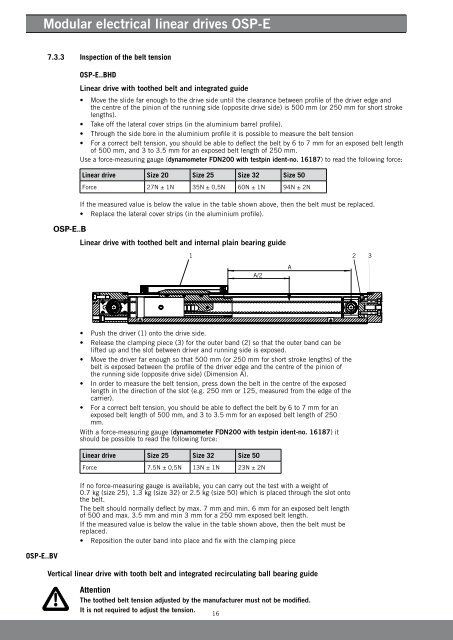
<strong>Modular</strong> <strong>electrical</strong> <strong>linear</strong> <strong>drives</strong> <strong>OSP</strong>-E7.3.3 Inspection of the belt tension<strong>OSP</strong>-E..BHDLinear drive with toothed belt and integrated guide• Move the slide far enough to the drive side until the clearance between profile of the driver edge andthe centre of the pinion of the running side (opposite drive side) is 500 mm (or 250 mm for short strokelengths).• Take off the lateral cover strips (in the aluminium barrel profile).• Through the side bore in the aluminium profile it is possible to measure the belt tension• For a correct belt tension, you should be able to deflect the belt by 6 to 7 mm for an exposed belt lengthof 500 mm, and 3 to 3.5 mm for an exposed belt length of 250 mm.Use a force-measuring gauge (dynamometer FDN200 with testpin ident-no. 16187) to read the following force:Linear drive Size 20 Size 25 Size 32 Size 50Force 27N ± 1N 35N ± 0,5N 60N ± 1N 94N ± 2N<strong>OSP</strong>-E..BIf the measured value is below the value in the table shown above, then the belt must be replaced.• Replace the lateral cover strips (in the aluminium profile).Linear drive with toothed belt and internal plain bearing guide• Push the driver (1) onto the drive side.• Release the clamping piece (3) for the outer band (2) so that the outer band can belifted up and the slot between driver and running side is exposed.• Move the driver far enough so that 500 mm (or 250 mm for short stroke lengths) of thebelt is exposed between the profile of the driver edge and the centre of the pinion ofthe running side (opposite drive side) (Dimension A).• In order to measure the belt tension, press down the belt in the centre of the exposedlength in the direction of the slot (e.g. 250 mm or 125, measured from the edge of thecarrier).• For a correct belt tension, you should be able to deflect the belt by 6 to 7 mm for anexposed belt length of 500 mm, and 3 to 3.5 mm for an exposed belt length of 250mm.With a force-measuring gauge (dynamometer FDN200 with testpin ident-no. 16187) itshould be possible to read the following force:Linear drive Size 25 Size 32 Size 50Force 7.5N ± 0,5N 13N ± 1N 23N ± 2N<strong>OSP</strong>-E..BVIf no force-measuring gauge is available, you can carry out the test with a weight of0.7 kg (size 25), 1.3 kg (size 32) or 2.5 kg (size 50) which is placed through the slot ontothe belt.The belt should normally deflect by max. 7 mm and min. 6 mm for an exposed belt lengthof 500 and max. 3.5 mm and min 3 mm for a 250 mm exposed belt length.If the measured value is below the value in the table shown above, then the belt must bereplaced.• Reposition the outer band into place and fix with the clamping pieceVertical <strong>linear</strong> drive with tooth belt and integrated recirculating ball bearing guideAttentionThe toothed belt tension adjusted by the manufacturer must not be modified.It is not required to adjust the tension.16