Style 232 Restrained Flexible Coupling For Carbon Steel ... - Victaulic
Style 232 Restrained Flexible Coupling For Carbon Steel ... - Victaulic
Style 232 Restrained Flexible Coupling For Carbon Steel ... - Victaulic

You also want an ePaper? Increase the reach of your titles
YUMPU automatically turns print PDFs into web optimized ePapers that Google loves.
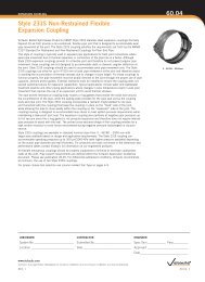
RESTRAINED COUPLING<strong>Style</strong> <strong>232</strong> <strong>Restrained</strong> <strong>Flexible</strong> <strong>Coupling</strong>60.05RESTRAINT RINGSdLZLCType 1 - Restraint Ring LocationZLCd L L ddBack Weld - Must notextend past the backedge of the restraint ringType 2 - Restraint Ring LocationZLCLType 3 - Restraint Ring LocationdEPipe EndSRestraint Ring Single FlareRestraint Ring Single FlareBevel Groove Weld DetailBevel Groove Weld DetaildEPipe EndSRestraint Ring Double FlareRestraint Bevel Groove Ring Double Weld Detail FlareBevel Groove Weld DetailLS(E)S(E)S(E)LddNominalPipeSizeIn./mm661650721800781950842100902250(1) (2)Restraint RingMaximumWorkingPressureWidth (Z) Diameter (d) Location (L)psi/kPa Body Type In./mm In./mm In./mm10012.504.1323/8690 317.5 104.815014.504.7521/21035 368.3 120.720015.004.5023/41375 381.0 114.325016.50313.751725 419.1 95.335016.50313.752410 419.1 95.310012.504.1323/8690 317.5 104.815014.504.7521/21035 368.3 120.720015.004.5023/41375 381.0 114.325016.50313.751725 419.1 95.335016.50313.752410 419.1 95.310012.504.1323/8690 317.5 104.815014.504.7521/21035 368.3 120.717515.004.5023/41200 381.0 114.320016.50313.751375 419.1 95.330016.50313.752065 419.1 95.310012.504.1323/8690 317.5 104.815014.504.7521/21035 368.3 120.717515.004.5023/41200 381.0 114.320016.50313.751375 419.1 95.330016.50313.752065 419.1 95.310012.504.1323/8690 317.5 104.812514.504.7521/2860 368.3 120.715015.004.5023/41035 381.0 114.320016.50313.751375 419.1 95.325016.50313.751725 419.1 95.3(3) (4)Weld Size (E)In.(1) <strong>For</strong> allowable test or transient pressure, the maximum working pressure may be increased to 11/2 times the values shown.(2) <strong>For</strong> applications other than air or gas, where a liquid or other medium is flowing through pipe, restraint ring weldrequirements are as follows:Type 1 couplings require a full circumferential single flare bevel groove weld based on weld sizes shown in table.Type 2 and Type 3 couplings require a full circumferential double flare bevel groove weld based on the weld sizesshown in the table.<strong>For</strong> low pressure air or gas applications, where the weight of the medium flowing through the pipe is not aconsideration, a single flare bevel groove weld and/or less than a full circumference of weld may be allowed toattach the restraint rings. Contact <strong>Victaulic</strong> for specific details. Each restraint ring shipment includes restraint ringplacement and welding data that is specific to application or project requirements.(3) Restraint rings must be welded perpendicular to the pipe axis with a tolerance of L± 1/16"/1.6 mm.(4) Flare bevel groove weld size in table is the minimum requirement. Depth of preparation S = (d) ÷ 2;Weld size E ≈ S * 0.625 per AWS D1.1. <strong>For</strong> a double flare bevel groove weld, the weld on the back side of therestraint ring must not extend beyond the outermost edge of the ring. The coupling shoulder must have unrestrictedcontact with the ring and the pipe O.D.Note: The data in this table only applies when carbon steel couplings are being used on carbon steel pipe.1/85/321/45/165/161/85/321/45/165/161/85/321/45/165/161/85/321/45/165/161/85/321/45/165/16www.victaulic.comVICTAULIC IS A REGISTERED TRADEMARK OF VICTAULIC COMPANY. © 2013 VICTAULIC COMPANY. ALL RIGHTS RESERVED.60.05_16REV_M