Style 232 Restrained Flexible Coupling For Carbon Steel ... - Victaulic
Style 232 Restrained Flexible Coupling For Carbon Steel ... - Victaulic
Style 232 Restrained Flexible Coupling For Carbon Steel ... - Victaulic

Create successful ePaper yourself
Turn your PDF publications into a flip-book with our unique Google optimized e-Paper software.
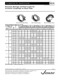
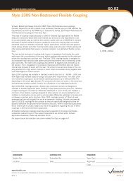
RESTRAINED COUPLING60.05<strong>Style</strong> <strong>232</strong> <strong>Restrained</strong> <strong>Flexible</strong> <strong>Coupling</strong><strong>Victaulic</strong> Bolted Split-Sleeve Products (VBSP) <strong>Style</strong> <strong>232</strong> carbon steel couplings (formerlyDepend-O-Lok FxF) provide a fully restrained, flexible pipe joint that satisfies the requirementsset forth by the AWWA C227 Standard for Bolted, Split-Sleeve <strong>Restrained</strong> and Non-<strong>Restrained</strong><strong>Coupling</strong>s for Plain-End Pipe.This style of coupling creates a restrained joint commonly used in buried or exposed pipeapplications for field joint connections where joint flexibility and thrust restraint is required.Typical applications include water and wastewater treatment pipelines, force main and watertransmission piping, slurry lines, penstocks and other piping applications that require arestrained, flexible connection. The coupling provides ease of installation and comes standardwith an epoxy coating for protection against corrosion. The use of a heat-shrink sleeve or tapesystem can be used with minimal effort due to the low profile configuration.The dual-arched coupling body houses o-ring gaskets that provide the radial seal around thecircumference of the pipe, while a sealing plate provides for the axial seal across the couplingbody and pipe joint. The <strong>Style</strong> <strong>232</strong> coupling incorporates a restraint ring welded to each pipeend (furnished with the coupling) allowing the coupling housing to straddle the restraint rings,and confining the rings under the coupling body in order to create a fully restrained joint. Thecoupling housing and restraint ring welds are designed to accommodate hoop stress and endloads to meet system pressure requirements. <strong>Style</strong> <strong>232</strong> restrained flexible couplings also performat negative pipe pressures up to full vacuum. The o-ring gasket is not pressure responsiveand therefore does not require internal pipe pressure to assist with the seal. The archedcross-sectional design provides stiffness to resist forces encountered during negative pressure(submerged) or vacuum service.<strong>Style</strong> <strong>232</strong> couplings are available in standard nominal sizes from 8 – 144"/200 – 3600 mmwith larger sizes available based on design and application requirements. The <strong>Style</strong> <strong>232</strong>restrained coupling can accommodate operating pressures up to 400 psi/2750 kPa (withhigher pressure available) depending on the actual pipe diameter and wall thickness. <strong>For</strong>pressures and sizes not shown in the dimension and performance tables contact <strong>Victaulic</strong> forinformation on our engineered products.<strong>Victaulic</strong> restrained couplings provide a flexible pipe connection and are not designed orintended to transfer significant shear or bending loads across the pipe joint. Therefore, a singlecoupling will not allow for differential settlement to occur at the joint. However, a minimumof two flexible couplings designed to allow dynamic (in-service) deflection, and installed incombination, can be used to accommodate differential settlement at a pipe joint or betweena pipeline and a structure. <strong>Victaulic</strong> recommends <strong>Style</strong> 233/233S couplings for this purposeas they are specifically designed to allow for dynamic deflection and provide thrust restraint atthe joint. Refer to publications 60.07 and 60.08 for product details and 26.20 for guidelinesregarding the use of these couplings in differential settlement applications.All flexible bolted spit-sleeve couplings require proper support to eliminate undesirable loadsat the joint. Pipe support requirements are defined within the Application Guidelines document.Please see publication 26.20.<strong>For</strong> proper closure tool selection see column marked Tool Type on pages 6-9.8 – 144"/200 – 3600mmJOB/OWNER CONTRACTOR ENGINEERSystem No.___________________________ Submitted By_________________________ Spec Sect_____________ Para___________Location_____________________________ Date ________________________________ Approved____________________________Date ________________________________www.victaulic.comVICTAULIC IS A REGISTERED TRADEMARK OF VICTAULIC COMPANY. © 2013 VICTAULIC COMPANY. ALL RIGHTS RESERVED.REV_M60.05_1
RESTRAINED COUPLING60.05<strong>Style</strong> <strong>232</strong> <strong>Restrained</strong> <strong>Flexible</strong> <strong>Coupling</strong>PRODUCT GUIDEProduct <strong>Style</strong> GuideSubmittal Number <strong>Style</strong> Number <strong>Coupling</strong>/Body Material Application60.01 230 <strong>Carbon</strong> <strong>Steel</strong> Non-<strong>Restrained</strong> <strong>Coupling</strong>60.02 230S Stainless <strong>Steel</strong> Non-<strong>Restrained</strong> <strong>Coupling</strong>60.03 231 <strong>Carbon</strong> <strong>Steel</strong> Expansion <strong>Coupling</strong>60.04 231S Stainless <strong>Steel</strong> Expansion <strong>Coupling</strong>60.05 <strong>232</strong> <strong>Carbon</strong> <strong>Steel</strong> <strong>Restrained</strong> <strong>Coupling</strong>60.06 <strong>232</strong>S Stainless <strong>Steel</strong> <strong>Restrained</strong> <strong>Coupling</strong>60.07 233 <strong>Carbon</strong> <strong>Steel</strong> <strong>Restrained</strong> <strong>Coupling</strong> <strong>For</strong> Dynamic Joint Deflection60.08 233S Stainless <strong>Steel</strong> <strong>Restrained</strong> <strong>Coupling</strong> <strong>For</strong> Dynamic Joint Deflection60.09 234 <strong>Carbon</strong> <strong>Steel</strong> <strong>Restrained</strong> Single-Gasket <strong>Coupling</strong>60.10 234S Stainless <strong>Steel</strong> <strong>Restrained</strong> Single-Gasket <strong>Coupling</strong>SEGMENTED COUPLINGSThe <strong>Style</strong> <strong>232</strong> dimension tables list the minimum number of coupling housing segments for a particularpipe size. <strong>For</strong> special applications, restrained couplings are available in two (or more) segments toallow for installation of the coupling over an existing pipe joint or to facilitate ease of handling for largersize couplings. The o-ring gaskets (except Silicone) can be furnished “split” to allow for field bondingwhen an existing pipe joint configuration does not allow for installation of a complete o-ring onto thepipe end.BODY TYPECross-SectionsNOTE: Body type is notoptional and will be determinedby system requirements.Type 1 coupling is the basic split-sleeve coupling that restrains pipe ends and is generally used for smallerdiameter, low pressure applications.Type 2 coupling is a shouldered coupling. This is a heavy duty coupling to accommodate higher pressures forcertain pipe diameters. The shoulders welded to the edge of the coupling body provide a vertical bearing surfacefor the restraint rings and provide additional cross-sectional stiffness.Type 3 coupling is a flat-body variation of the Type 2 with a reinforced, offset closure and thick body design forhigh pressure applications. As with all <strong>Style</strong> <strong>232</strong> couplings, the Type 3 coupling is designed to restrain the pipeends at full axial thrust generated by higher operating pressures.www.victaulic.comVICTAULIC IS A REGISTERED TRADEMARK OF VICTAULIC COMPANY. © 2013 VICTAULIC COMPANY. ALL RIGHTS RESERVED.60.05_2REV_M
RESTRAINED COUPLING60.05<strong>Style</strong> <strong>232</strong> <strong>Restrained</strong> <strong>Flexible</strong> <strong>Coupling</strong>COUPLING COMPONENTS1. Body – Dual arch cross-section used on Type 1 and Type 2. A thick, flat cross-section is used forType 3.2. Shoulders (Type 2 and Type 3 only) – Provide additional stiffness, allow for larger o-ring gasketand provide vertical bearing surface for restraint rings.3. Closure Plates – Low profile bolt pads for installation and tightening of coupling; gap betweenplates of installed coupling allows for field flexibility.4. Sealing Plate – Provides axial seal across the coupling body and pipe joint.5. O-ring Gaskets – Provide circumferential seal.6. FastenersStuds – High Strength Threaded RodNuts – Heavy Hex NutsWashers – SAE small pattern flat washers7. Restraint Rings – Attached to pipe ends to create a restrained joint.15475126246733ONE SEGMENT HOUSINGTWO SEGMENT HOUSINGwww.victaulic.comVICTAULIC IS A REGISTERED TRADEMARK OF VICTAULIC COMPANY. © 2013 VICTAULIC COMPANY. ALL RIGHTS RESERVED.REV_M60.05_3
RESTRAINED COUPLING<strong>Style</strong> <strong>232</strong> <strong>Restrained</strong> <strong>Flexible</strong> <strong>Coupling</strong>60.05MATERIAL SPECIFICATIONSBody<strong>Carbon</strong> <strong>Steel</strong> conforming to ASTM A36 or ASTM A1011 (for gauge thicknesses)Shoulders (Type 2 and Type 3)<strong>Carbon</strong> <strong>Steel</strong> conforming to ASTM A36Closure Plates<strong>Carbon</strong> <strong>Steel</strong> conforming to ASTM A36Sealing PlateStainless <strong>Steel</strong> conforming to ASTM A240 316LO-ring GasketsStandard (Specify choice on order):• EPDM -30ºF to +230ºF/-34ºC to +110ºCCold and hot water within allowable temperature range; dilute acids; excellent resistance tothe deteriorative effects of ozone, oxygen, heat and most chemicals not involving hydrocarbons.NOT RECOMMENDED FOR PETROLEUM SERVICES.• Silicone -30ºF to +350ºF/-34ºC to +177ºCDry, hot air applications; excellent resistance to many chemicals.NOT RECOMMENDED FOR HOT WATER OR STEAM APPLICATIONS.• Isoprene -40ºF to +160ºF/-40ºC to +71ºCWater; salt water; sewage; good resistance to oxygen and dilute acidsServices listed are general service recommendations only. Refer to a chemical elastomer guidefor specific applications and suitability of gasket material for services that are not listed.Optional gasket (specify choice on order):• Nitrile -20ºF to +180ºF/-28ºC to +82ºCWater; petroleum products, vegetable and mineral oils; air with oil vapors within allowable temperaturerange; good resistance to hydrocarbons; acids and bases.• Fluouroelastomer +20ºF to +300ºF/-7ºC to +149ºCOutstanding resistance to heat and most chemicals.• Neoprene -30ºF to +180ºF/-34ºC to +82ºCWater and wastewater; good resistance to ozone, effects of UV and some oils.• Services listed are general service recommendations only. Refer to a chemical elastomer guide forRestraint Ringsspecific applications and suitability of gasket material for services that are not listed.<strong>Carbon</strong> <strong>Steel</strong> conforming to ASTM A108 Grade 1018FastenersStuds - <strong>Carbon</strong> <strong>Steel</strong> conforming to ASTM A193 Grade B7 zinc plated.Optional: Stainless <strong>Steel</strong> conforming to ASTM A193 Grade B8M 316 Class 2Nuts - Heavy hex nuts<strong>Carbon</strong> <strong>Steel</strong> conforming to ASTM A194 Grade 2H zinc platedOptional: Stainless <strong>Steel</strong> conforming to ASTM A194 Grade 8M 316Washers - <strong>Carbon</strong> <strong>Steel</strong> SAE small pattern flat washers conforming to ASTM F436 SAE pattern zinc platedOptional: Stainless <strong>Steel</strong> Type 316 SAE pattern.www.victaulic.comVICTAULIC IS A REGISTERED TRADEMARK OF VICTAULIC COMPANY. © 2013 VICTAULIC COMPANY. ALL RIGHTS RESERVED.60.05_4REV_M
RESTRAINED COUPLING60.05<strong>Style</strong> <strong>232</strong> <strong>Restrained</strong> <strong>Flexible</strong> <strong>Coupling</strong>LININGS AND COATINGSStandard (specify choice on order):• Liquid Epoxy:Liquid epoxy is applied per AWWA C210, 16 mils minimum DFT and is NSF61 approved. Epoxy canbe applied as a primer for field applied top coat where UV protection due to sunlight exposure isrequired. A supplemental corrosion protection system such as heat shrink sleeve or tape coat systemis recommended for buried applications.• Fusion Bonded Epoxy:Fusion bonded epoxy is applied with an electrostatic spray system using a long cure epoxy powderthat offers excellent chemical resistance and corrosion protection. Fusion bonded epoxy is appliedper AWWA C213, 12 mils minimum DFT and is NSF61 approved.Optional (specify choice on order):• Phenolic Alkyd Primer:Phenolic Alkyd primer is a lead-free and chromate-free, fast-drying, corrosion-resistant primer thataccepts a variety of high-performance topcoats, but is not recommended for immersion service byitself. This primer system is typically applied at 2 to 3 mils DFT.• Other Coating Systems (Available Upon Request):A water based enamel coating is available. This paint offers an aesthetic coating for minimal protection,short-term installations or where corrosion protection is not a consideration. Fusion bondednylon for chemical and abrasion resistance, as well as other coatings such as organic zinc primersand hot dipped galvanizing may be available upon request may also be available.PIPE END DIMENSIONALTOLERANCE AND OVALITY<strong>For</strong> specific pipe diameter tolerances, pipe ovality (roundness) requirements and minimum/maximumpipe diameter allowance, refer to the tables included in the Installation Manuals (below) and 26.20Application Guidelines.I-<strong>232</strong>.S1 - <strong>Style</strong>s <strong>232</strong>/<strong>232</strong>S <strong>Restrained</strong> <strong>Coupling</strong> (Types 1 & 2, One-Segment)I-<strong>232</strong>.S2 - <strong>Style</strong>s <strong>232</strong>/<strong>232</strong>S <strong>Restrained</strong> <strong>Coupling</strong> (Types 1 & 2, Two-Segments)I-<strong>232</strong>.T3S2 - <strong>Style</strong> <strong>232</strong> <strong>Restrained</strong> <strong>Coupling</strong> (Type 3, Two-Segments)www.victaulic.comVICTAULIC IS A REGISTERED TRADEMARK OF VICTAULIC COMPANY. © 2013 VICTAULIC COMPANY. ALL RIGHTS RESERVED.REV_M60.05_5
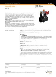
RESTRAINED COUPLING<strong>Style</strong> <strong>232</strong> <strong>Restrained</strong> <strong>Flexible</strong> <strong>Coupling</strong>60.05DIMENSIONSZ1-SEGMENTZ(1) (2) (3) <strong>Coupling</strong> Dimensions (4) (5) (6)NominaIPipeSizeIn./mm820010250123001435016400184502050024600ActualPipe O.D.RangeIn./mm7.00 - 8.88177.8 - 225.69.00 - 10.88228.6 - 276.411.00 - 12.88279.4 - 327.213.00 - 14.88330.2 - 378.015.00 - 16.88381.0 - 428.817.00 - 18.88431.8 - 479.619.00 - 21.88482.6 - 555.822.00 - 26.88558.8 - 682.8MaximumWorkingPressurepsi/kPa200BodyThicknessIn.Width(Z)In./mm10.00Min. No. of<strong>Coupling</strong>SegmentsNo. of Fasteners -Fastener DimensionsDia. x LengthIn. x In.ApproximateWeightEachLbs/Kg.21.011 ga.1 3 - 5/8 x 51375 254.0 9.530010 ga.10.501 3 - 5/8 x 528.02065 266.7 12.720010 ga.10.001 3 - 5/8 x 524.01375 254.0 10.93003/1610.501 3 - 5/8 x 541.02065 266.7 18.615010 ga.10.001 3 - 5/8 x 528.01035 254.0 12.73003/1610.501 3 - 3/4 x 645.02065 266.7 20.410010 ga.10.001 3 - 5/8 x 531.0690 254.0 14.13003/1610.501 3 - 3/4 x 650.02065 266.7 22.7753/1610.001 3 - 3/4 x 644.0515 254.0 20.02003/1610.501 3 - 3/4 x 657.01375 266.7 25.93001/412.501 4 - 3/4 x 685.02065 317.5 38.6503/1610.001 3 - 3/4 x 648.0345 254.0 21.82003/1610.501 3 - 3/4 x 662.01375 266.7 28.13001/412.501 4 - 3/4 x 694.02065 317.5 42.6253/1610.001 3 - 3/4 x 652.0170 254.0 23.62003/1610.501 3 - 3/4 x 668.01375 266.7 30.83001/412.501 4 - 3/4 x 6102.02065 317.5 46.3253/1610.001 3 - 3/4 x 661.0170 254.0 27.71503/1610.501 3 - 3/4 x 681.01035 266.7 36.72501/412.501 4 - 3/4 x 6119.01725 317.5 54.03003/812.502 8 - 7/8 x 8248.02065 317.5 112.5(1) <strong>Coupling</strong>s must be used on pipe with a minimum wall thickness that meets the requirements of AWWA C200 for carbon steel pipe.(2) <strong>For</strong> actual Pipe O.D. round down to the nearest 1/8" to determine proper coupling size required.(3) <strong>For</strong> allowable test or transient pressure, the maximum working pressure may be increased to 11/2 times the values shown.(4) 1-segment couplings may be available as 2-segment couplings to allow for in-place pipe installations. Contact <strong>Victaulic</strong> for details.(5) <strong>Coupling</strong> weights are based on nominal pipe diameter and include all accessories. Weight may vary based on actual size of pipe.(6) Closure Tool Recommendations:*A= CTM-01 Small Manual Closure ToolB= CTM-02 Large Manual Closure ToolC= CTH-01 10-Ton Hydraulic Closure ToolD= CTH-02 25-Ton Hydraulic Closure Tool*<strong>For</strong> more details on closure tools refer to page 18.Note: The data in this table only applies when carbon steel couplings are being used on carbon steel pipe.BodyTypeToolType1 B,C2 B,C1 B,C2 B,C1 B,C2 B,C1 B,C2 B,C1 B,C2 B,C2 C1 B,C2 B,C2 C1 B,C2 B,C2 C1 B,C2 B,C2 C2 C2-SEGMENTwww.victaulic.comVICTAULIC IS A REGISTERED TRADEMARK OF VICTAULIC COMPANY. © 2013 VICTAULIC COMPANY. ALL RIGHTS RESERVED.60.05_6REV_M
RESTRAINED COUPLING<strong>Style</strong> <strong>232</strong> <strong>Restrained</strong> <strong>Flexible</strong> <strong>Coupling</strong>60.05DIMENSIONSZ1-SEGMENTZ(1) (2) (3) <strong>Coupling</strong> Dimensions (4) (5) (6)NominaIPipeSizeIn./mm3075036900421050481200541350601500ActualPipe O.D.RangeIn./mm27.00 - 32.88685.8 - 835.233.00 - 38.88838.2 - 987.639.00 - 44.88990.6 - 1140.045.00 - 50.881143.0 - 1292.451.00 - 56.881295.4 - 1444.857.00 - 62.881447.8 - 1597.2MaximumWorkingPressurepsi/kPa100BodyThicknessIn.Width(Z)In./mm10.50Min. No. of<strong>Coupling</strong>SegmentsNo. of Fasteners -Fastener DimensionsDia. x LengthIn. x In.ApproximateWeightEachLbs/Kg.97.03/161 3 - 3/4 x 6690 266.7 44.02001/412.501 4 - 3/4 x 6146.01375 317.5 66.23003/812.502 8 - 7/8 x 8293.02065 317.5 132.91501/412.501 4 - 3/4 x 6171.01035 317.5 77.62503/812.502 8 - 7/8 x 8337.01725 317.5 152.93001/214.502 8 - 1 x 8520.02065 368.3 235.91501/412.501 4 - 3/4 x 6195.01035 317.5 88.52003/812.502 8 - 7/8 x 8381.01375 317.5 172.83001/214.502 8 - 1 x 8590.02065 368.3 267.61001/412.501 4 - 3/4 x 6220.0690 317.5 99.81503/812.502 8 - 7/8 x 8425.01035 317.5 192.82501/214.502 8 - 1 x 8658.01725 368.3 298.53005/815.002864.02065 381.0 8 - 1 x 8391.91503/812.502 8 - 7/8 x 8459.01035 317.5 208.22001/214.502 8 - 1 x 8727.01375 368.3 329.82505/815.002 8 - 1 x 8956.01725 381.0 433.63003/416.502 10 - 11/4 x 101434.02065 419.1 650.5400116.502 10 - 11/4 x 101708.02750 419.1 774.71503/812.502 8 - 7/8 x 8503.01035 317.5 228.22001/214.502 8 - 1 x 8796.01375 368.3 361.12505/815.002 8 - 1 x 81047.01725 381.0 474.93003/416.502 10 - 11/4 x 101567.02065 419.1 710.8400116.5021869.02750 419.1 10 - 11/4 x 10 847.8(1) <strong>Coupling</strong>s must be used on pipe with a minimum wall thickness that meets the requirements of AWWA C200 for carbon steel pipe.(2) <strong>For</strong> actual Pipe O.D. round down to the nearest 1/8" to determine proper coupling size required.(3) <strong>For</strong> allowable test or transient pressure, the maximum working pressure may be increased to 11/2 times the values shown.(4) 1-segment couplings may be available as 2-segment couplings to allow for in-place pipe installations. Contact <strong>Victaulic</strong> for details.(5) <strong>Coupling</strong> weights are based on nominal pipe diameter and include all accessories. Weight may vary based on actual size of pipe.(6) Closure Tool Recommendations:*A= CTM-01 Small Manual Closure ToolB= CTM-02 Large Manual Closure ToolC= CTH-01 10-Ton Hydraulic Closure ToolD= CTH-02 25-Ton Hydraulic Closure Tool*<strong>For</strong> more details on closure tools refer to page 18.Note: The data in this table only applies when carbon steel couplings are being used on carbon steel pipe.BodyTypeToolType2 B,C2 C2 C2 C2 C2 C2 C2 C2 C2 C2 C2 C2 C2 C2 C2 C3 D3 D2 C2 C2 C3 D3 D2-SEGMENTwww.victaulic.comVICTAULIC IS A REGISTERED TRADEMARK OF VICTAULIC COMPANY. © 2013 VICTAULIC COMPANY. ALL RIGHTS RESERVED.REV_M60.05_7
RESTRAINED COUPLING<strong>Style</strong> <strong>232</strong> <strong>Restrained</strong> <strong>Flexible</strong> <strong>Coupling</strong>60.05DIMENSIONSZ1-SEGMENTZ2-SEGMENT(1) (2) (3) <strong>Coupling</strong> Dimensions (4) (5) (6)NominaIPipeSizeIn./mm661650721800781950842100902250ActualPipe O.D.RangeIn./mm63.00 - 68.881600.2 - 1749.669.00 - 74.881752.6 - 1902.075.00 - 80.881905.0 - 2054.481.00 - 86.882057.4 - 2206.887.00 - 92.882209.8 - 2359.2MaximumWorkingPressurepsi/kPa100BodyThicknessIn.Width(Z)In./mm12.50Min. No. of<strong>Coupling</strong>SegmentsNo. of Fasteners -Fastener DimensionsDia. x LengthIn. x In.ApproximateWeightEachLbs/Kg.537.03/82 8 - 7/8 x 8690 317.5 243.61501/214.502 8 - 1 x 8849.01035 368.3 385.12005/815.002 8 - 1 x 81139.01375 381.0 516.62503/416.502 10 - 11/4 x 101675.01725 419.1 759.8350116.502 10 - 1 1/4 x 101997.02410 419.1 905.81003/812.502 8 - 7/8 x 8581.0690 317.5 263.51501/214.502 8 - 1 x 8918.01035 368.3 416.42005/815.002 8 - 1 x 81231.01375 381.0 558.42503/416.502 10 - 11/4 x 101816.01725 419.1 823.7350116.502 10 - 1 1/4 x 102169.02410 419.1 983.91003/812.502 8 - 7/8 x 8614.0690 317.5 278.51501/214.502 8 - 1 x 8987.01035 368.3 447.71755/815.002 8 - 1 x 81322.01200 381.0 599.62003/416.502 10 - 11/4 x 101924.01375 419.1 872.7300116.502 10 - 1 1/4 x 102297.02065 419.1 1041.91003/812.502 8 - 7/8 x 8658.0690 317.5 298.51501/214.502 8 - 1 x 81040.01035 368.3 471.11755/815.002 8 - 1 x 81394.01200 381.0 632.32003/416.502 10 - 11/4 x 102056.01375 419.1 932.6300116.502 10 - 1 1/4 x 102458.02065 419.1 1114.91003/812.502 8 - 7/8 x 8692.0690 317.5 313.91251/214.502 8 - 1 x 81093.0860 368.3 495.81505/815.002 8 - 1 x 81485.01035 381.0 673.62003/416.502 10 - 11/4 x 102170.01375 419.1 984.3250116.502 10 - 1 1/4 x 102594.01725 419.1 1176.6(1) <strong>Coupling</strong>s must be used on pipe with a minimum wall thickness that meets the requirements of AWWA C200 for carbon steel pipe.(2) <strong>For</strong> actual Pipe O.D. round down to the nearest 1/8" to determine proper coupling size required.(3) <strong>For</strong> allowable test or transient pressure, the maximum working pressure may be increased to 11/2 times the values shown.(4) 1-segment couplings may be available as 2-segment couplings to allow for in-place pipe installations. Contact <strong>Victaulic</strong> for details.(5) <strong>Coupling</strong> weights are based on nominal pipe diameter and include all accessories. Weight may vary based on actual size of pipe.(6) Closure Tool Recommendations:*A= CTM-01 Small Manual Closure ToolB= CTM-02 Large Manual Closure ToolC= CTH-01 10-Ton Hydraulic Closure ToolD= CTH-02 25-Ton Hydraulic Closure Tool*<strong>For</strong> more details on closure tools refer to page 18.Note: The data in this table only applies when carbon steel couplings are being used on carbon steel pipe.BodyTypeToolType2 C2 C2 C3 D3 D2 C2 C2 C3 D3 D2 C2 C2 C3 D3 D2 C2 C2 C3 D3 D2 C2 C2 C3 D3 Dwww.victaulic.comVICTAULIC IS A REGISTERED TRADEMARK OF VICTAULIC COMPANY. © 2013 VICTAULIC COMPANY. ALL RIGHTS RESERVED.60.05_8REV_M
RESTRAINED COUPLING<strong>Style</strong> <strong>232</strong> <strong>Restrained</strong> <strong>Flexible</strong> <strong>Coupling</strong>60.05DIMENSIONSZ1-SEGMENTZ(1) (2) (3) <strong>Coupling</strong> Dimensions (4) (5) (6)NominaIPipeSizeIn./mm962400108270012030001443600ActualPipe O.D.RangeIn./mm93.00 - 101.882362.2 - 2587.8102.00 - 113.882590.8 - 2892.6114.00 - 125.882895.6 - 3197.4126.00 - 150.003200.4 - 3810.0MaximumWorkingPressurepsi/kPa100BodyThicknessIn.Width(Z)In./mm12.50Min. No. of<strong>Coupling</strong>SegmentsNo. of Fasteners -Fastener DimensionsDia. x LengthIn. x In.ApproximateWeightEachLbs/Kg.745.03/82 8 - 7/8 x 8690 317.5 337.91251/214.502 8 - 1 x 81176.0860 368.3 533.41505/815.002 8 - 1 x 81595.01035 381.0 723.52003/416.502 10 - 11/4 x 102277.01375 419.1 1032.8250116.502 10 - 1 1/4 x 102721.01725 419.1 1234.2753/812.502 8 - 7/8 x 8813.0515 317.5 368.81001/214.502 8 - 1 x 81298.0690 368.3 588.81503/416.502 10 - 1 1/4 x 102493.01035 419.1 1130.8200116.502 10 - 1 1/4 x 102977.01375 419.1 1350.3753/812.502 8 - 7/8 x 8890.0515 317.5 403.71001/214.502 8 - 1 x 81420.0690 368.3 644.11503/416.502 10 - 1 1/4 x 102741.01035 419.1 1243.3200116.502 10 - 1 1/4 x 103275.01375 419.1 1485.5503/812.502 8 - 7/8 x 81026.0345 317.5 465.41005/815.002 8 - 1 x 82249.0690 381.0 1020.11253/416.502 10 - 1 1/4 x 103173.0860 419.1 1439.2175116.502 10 - 1 1/4 x 103788.01200 419.1 1718.2(1) <strong>Coupling</strong>s must be used on pipe with a minimum wall thickness that meets the requirements of AWWA C200 for carbon steel pipe.(2) <strong>For</strong> actual Pipe O.D. round down to the nearest 1/8" to determine proper coupling size required.(3) <strong>For</strong> allowable test or transient pressure, the maximum working pressure may be increased to 11/2 times the values shown.(4) 1-segment couplings may be available as 2-segment couplings to allow for in-place pipe installations. Contact <strong>Victaulic</strong> for details.(5) <strong>Coupling</strong> weights are based on nominal pipe diameter and include all accessories. Weight may vary based on actual size of pipe.(6) Closure Tool Recommendations:*A= CTM-01 Small Manual Closure ToolB= CTM-02 Large Manual Closure ToolC= CTH-01 10-Ton Hydraulic Closure ToolD= CTH-02 25-Ton Hydraulic Closure Tool*<strong>For</strong> more details on closure tools refer to page 18.Note: The data in this table only applies when carbon steel couplings are being used on carbon steel pipe.BodyTypeToolType2 C2 C2 C3 D3 D2 C2 C3 D3 D2 C2 C3 D3 D2 C2 C3 D3 D2-SEGMENTwww.victaulic.comVICTAULIC IS A REGISTERED TRADEMARK OF VICTAULIC COMPANY. © 2013 VICTAULIC COMPANY. ALL RIGHTS RESERVED.REV_M60.05_9
RESTRAINED COUPLING<strong>Style</strong> <strong>232</strong> <strong>Restrained</strong> <strong>Flexible</strong> <strong>Coupling</strong>60.05PERFORMANCENominalPipeDiameterIn./mm820010250123001435016400184502050024600MaximumWorkingPressurepsi/kPa<strong>Carbon</strong> <strong>Steel</strong>(1) (2) (3) (3) (4) (5)MaximumWorkingPressurepsi/kPaStainless <strong>Steel</strong>MaximumWorkingPressurepsi/kPaDuctile IronPipe EndSeparationMin - MaxIn./mm0.38 - 0.75Max.Allow. StaticDeflectionDegreesMax.PermissibleEnd Loadlbf/N10053Body Type200 200 20014° 0'1375 1375 1375 9.7 - 19.1 44718300 300 3000.38 - 0.7524° 0'150802065 2065 2065 9.7 - 19.1 67078200 200 2000.38 - 0.7513° 30'157081375 1375 1375 9.7 - 19.1 69873300 300 3000.38 - 0.7523° 30'235622065 2065 2065 9.7 - 19.1 104809150 150 1500.38 - 0.7513° 15'169651035 1035 1035 9.7 - 19.1 75462300 300 2500.38 - 0.7523° 15'339292065 2065 1725 9.7 - 19.1 150935100 100 1000.38 - 0.7513° 0'15394690 690 690 9.7 - 19.1 68475300 300 2500.38 - 0.7523° 0'461812065 2065 1725 9.7 - 19.1 20542575 75 750.38 - 0.7512° 30'15080515 515 515 9.7 - 19.1 67078200 200 2000.38 - 0.7522° 30'402121375 1375 1375 9.7 - 19.1 178874300 300 3000.63 - 1.0022° 30'603192065 2065 2065 16.0 - 25.4 26831050 50 500.38 - 0.7512° 15'12723345 345 345 9.7 - 19.1 56597200 200 1750.38 - 0.7522° 15'508941375 1375 1200 9.7 - 19.1 226387300 300 2500.63 - 1.0022° 15'763412065 2065 1725 16.0 - 25.4 33958025 25 250.38 - 0.7512° 0'7854170 170 170 9.7 - 19.1 34936200 200 1500.38 - 0.7522° 0'628321375 1375 1035 9.7 - 19.1 279490300 300 2500.63 - 1.0022° 0'942482065 2065 1725 16.0 - 25.4 41923525 25 250.38 - 0.7511° 45'11310170 170 170 9.7 - 19.1 50308150 150 1250.38 - 0.7521° 45'678581035 1035 860 9.7 - 19.1 301849250 250 2000.63 - 1.0021° 45'1130971725 1725 1375 16.0 - 25.4 503082300 250 2000.63 - 1.0021° 45'1357172065 1725 1375 16.0 - 25.4 603398(1) <strong>For</strong> allowable test or transient pressure, the maximum working pressure may be increased to 1 1/2 times the value shown.(2) Pipe end separations shown in the table assume the pipe is in a non-deflected state. Maximum allowable axial pipe movement at the joint is thedifference between the maximum and minimum pipe separation. At maximum pipe end separation, axial movement can only occur via pipeexpansion into the joint and vice versa.(3) Pipe end movement and deflection are non-concurrent.(4) Published static deflection values are intended for installation only. <strong>For</strong> allowable in-service or dynamic deflection, use 1/2 of the published staticvalues. The coupling closure should be located 90 degrees from the direction of joint deflection.(5) The maximum permissible end loads listed in the table are calculated using the nominal pipe O.D. The actual maximum permissible end loadwill be less or greater than the published figures depending on the actual pipe O.D.www.victaulic.comVICTAULIC IS A REGISTERED TRADEMARK OF VICTAULIC COMPANY. © 2013 VICTAULIC COMPANY. ALL RIGHTS RESERVED.60.05_10REV_M
RESTRAINED COUPLING<strong>Style</strong> <strong>232</strong> <strong>Restrained</strong> <strong>Flexible</strong> <strong>Coupling</strong>60.05PERFORMANCENominalPipeSizeIn./mm3075036900421050481200541350601500MaximumWorkingPressurepsi/kPa<strong>Carbon</strong> <strong>Steel</strong>(1) (2) (3) (3) (4) (5)MaximumWorkingPressurepsi/kPaStainless <strong>Steel</strong>MaximumWorkingPressurepsi/kPaDuctile IronPipe EndSeparationMin - MaxIn./mm0.38 - 0.75Max.Allow. StaticDeflectionDegreesMax.PermissibleEnd Loadlbf/N70686Body Type100 100 10021° 15'690 690 690 9.7 - 19.1 314426200 200 1500 .63 - 1.0021° 15'1413721375 1375 1035 16.0 - 25.4 628853300 200 1500 .63 - 1.0021° 15'2120582065 1375 1035 16.0 - 25.4 943279150 150 1250 .63 - 1.0021° 6'1526811035 1035 860 16.0 - 25.4 679161250 175 1250 .63 - 1.0021° 6'2544691725 1200 860 16.0 - 25.4 1131935300 200 1750 .63 - 1.0021° 6'3053632065 1375 1200 16.0 - 25.4 1358322150 150 1250 .63 - 1.0021° 0'2078161035 1035 860 16.0 - 25.4 924413200 150 1250 .63 - 1.0021° 0'2770881375 1035 860 16.0 - 25.4 1<strong>232</strong>551300 300 1500 .63 - 1.0031° 0'4156332065 1375 1035 16.0 - 25.4 1848827100 100 1000 .63 - 1.0020° 50'189056690 690 690 16.0 - 25.4 804931150 125 1000 .63 - 1.0020° 50'2714341035 860 690 16.0 - 25.4 1207397250 175 1250 .63 - 1.0020° 50'4523891725 1200 860 16.0 - 25.4 201<strong>232</strong>8300 250 2000 .63 - 1.0020° 50'5428672065 1725 1375 16.0 - 25.4 2414794150 100 750 .63 - 1.0020° 45'3435331035 690 515 16.0 - 25.4 1528112200 150 1250 .63 - 1.0020° 45'4580441375 1035 860 16.0 - 25.4 2037482250 200 1750 .63 - 1.0020° 45'5725551725 1375 1200 16.0 - 25.4 2546853300 300 2500 .75 - 1.0030° 30'6870662065 2065 1725 19.1 - 25.4 3056223400 300 2500 .75 - 1.0030° 30'9160882750 2065 1725 19.1 - 25.4 4074965150 100 750 .63 - 1.0020° 40'4241151035 690 515 16.0 - 25.4 1886558200 125 1000 .63 - 1.0020° 40'5654871375 860 690 16.0 - 25.4 2515410250 200 1750 .63 - 1.0020° 40'7068581725 1375 1200 16.0 - 25.4 3144263300 250 2000 .75 - 1.0030° 27'8482302065 2065 1375 19.1 - 25.4 3773115400 250 2000 .75 - 1.0030° 27'11309732750 1725 1375 19.1 - 25.4 5030821(1) <strong>For</strong> allowable test or transient pressure, the maximum working pressure may be increased to 1 1/2 times the value shown.(2) Pipe end separations shown in the table assume the pipe is in a non-deflected state. Maximum allowable axial pipe movement at the joint is thedifference between the maximum and minimum pipe separation. At maximum pipe end separation, axial movement can only occur via pipeexpansion into the joint and vice versa.(3) Pipe end movement and deflection are non-concurrent.(4) Published static deflection values are intended for installation only. <strong>For</strong> allowable in-service or dynamic deflection, use 1/2 of the published staticvalues. The coupling closure should be located 90 degrees from the direction of joint deflection.(5) The maximum permissible end loads listed in the table are calculated using the nominal pipe O.D. The actual maximum permissible end loadwill be less or greater than the published figures depending on the actual pipe O.D.www.victaulic.comVICTAULIC IS A REGISTERED TRADEMARK OF VICTAULIC COMPANY. © 2013 VICTAULIC COMPANY. ALL RIGHTS RESERVED.REV_M60.05_11
RESTRAINED COUPLING<strong>Style</strong> <strong>232</strong> <strong>Restrained</strong> <strong>Flexible</strong> <strong>Coupling</strong>60.05PERFORMANCENominalPipeSizeIn./mm661650721800781950842100902250MaximumWorkingPressurepsi/kPa<strong>Carbon</strong> <strong>Steel</strong>(1) (2) (3) (3) (4) (5)MaximumWorkingPressurepsi/kPaStainless <strong>Steel</strong>MaximumWorkingPressurepsi/kPaDuctile IronPipe EndSeparationMin - MaxIn./mm0.63 - 1.00Max. Allow. Max. PermissibleStatic DeflectionDegreesEnd Loadlbf/N0° 37'342119Body Type100 100 75690 690 515 2 16.0 - 25.4 1521823150 125 1000.63 - 1.0020° 37'5131791035 860 690 16.0 - 25.4 2282735200 200 1500.63 - 1.0020° 37'6842391375 1375 1035 16.0 - 25.4 3043646250 250 2000.75 - 1.0030° 24'8552991725 1725 1375 19.1 - 25.4 3804558350 250 2000.75 - 1.0030° 24'11974182410 1725 1375 19.1 - 25.4 5326381100 75 750.63 - 1.0020° 30'407150690 515 515 16.0 - 25.4 1811095150 125 1000.63 - 1.0020° 30'6107261035 860 690 16.0 - 25.4 2716643200 175 1500.63 - 1.0020° 30'8143011375 1200 1035 16.0 - 25.4 3622191250 250 2000.75 - 1.0030° 22'10178761725 1725 1375 19.1 - 25.4 4527739350 250 2000.75 - 1.0030° 22'14250262410 1725 1375 19.1 - 25.4 6338834100 75 500.63 - 1.0020° 34'477836690 515 345 16.0 - 25.4 2125522150 100 750.63 - 1.0020° 34'7167541035 690 515 16.0 - 25.4 3188283175 150 1250.63 - 1.0020° 34'8362131200 1035 860 16.0 - 25.4 3719663200 200 1750.75 - 1.0030° 22'9556721375 1375 1200 19.1 - 25.4 4251043300 200 1750.75 - 1.0030° 22'14335092065 1375 1200 19.1 - 25.4 6376565100 75 500.63 - 1.0020° 29'554177690 515 345 16.0 - 25.4 2465102150 100 750.63 - 1.0020° 29'8312651035 690 515 16.0 - 25.4 3697653175 150 1250.63 - 1.0020° 29'9698101200 1035 860 16.0 - 25.4 4313929200 200 1500.75 - 1.0030° 19'11083541375 1375 1035 19.1 - 25.4 4930204300 200 1500.75 - 1.0030° 19'16625312065 1375 1035 19.1 - 25.4 7395306100 75 500.63 - 1.0020° 27'636173690 515 345 16.0 - 25.4 2829837125 100 750.63 - 1.0020° 27'795216860 690 5115 16.0 - 25.4 3537296150 150 1000.63 - 1.0020° 27'9542591035 1035 690 16.0 - 25.4 4244755200 200 1500.75 - 1.0030° 18'12723451375 1375 1035 19.1 - 25.4 5659673250 200 1500.75 - 1.0030° 18'15904311725 1375 1035 19.1 - 25.4 7074591(1) <strong>For</strong> allowable test or transient pressure, the maximum working pressure may be increased to 1 1/2 times the value shown.(2) Pipe end separations shown in the table assume the pipe is in a non-deflected state. Maximum allowable axial pipe movement at the joint is thedifference between the maximum and minimum pipe separation. At maximum pipe end separation, axial movement can only occur via pipeexpansion into the joint and vice versa.(3) Pipe end movement and deflection are non-concurrent.(4) Published static deflection values are intended for installation only. <strong>For</strong> allowable in-service or dynamic deflection, use 1/2 of the published staticvalues. The coupling closure should be located 90 degrees from the direction of joint deflection.(5) The maximum permissible end loads listed in the table are calculated using the nominal pipe O.D. The actual maximum permissible end loadwill be less or greater than the published figures depending on the actual pipe O.D.www.victaulic.comVICTAULIC IS A REGISTERED TRADEMARK OF VICTAULIC COMPANY. © 2013 VICTAULIC COMPANY. ALL RIGHTS RESERVED.60.05_12REV_M
RESTRAINED COUPLING<strong>Style</strong> <strong>232</strong> <strong>Restrained</strong> <strong>Flexible</strong> <strong>Coupling</strong>60.05PERFORMANCENominalPipeSizeIn./mm962400108270012030001443600MaximumWorkingPressurepsi/kPa<strong>Carbon</strong> <strong>Steel</strong>(1) (2) (3) (3) (4) (5)MaximumWorkingPressurepsi/kPaStainless <strong>Steel</strong>MaximumWorkingPressurepsi/kPaDuctile IronPipe EndSeparationMin - MaxIn./mm0.63 - 1.00Max. Allow. Max. PermissibleStatic DeflectionDegreesEnd Loadlbf/N0° 25'723823Body Type100 50 50690 345 345 2 16.0 - 25.4 3219725125 75 500.63 - 1.0020° 25'904779860 515 345 16.0 - 25.4 4024656150 125 1000.63 - 1.0020° 25'10857341035 1200 690 16.0 - 25.4 4829588200 175 1250.75 - 1.0030° 16'14476461375 1200 860 19.1 - 25.4 6439450250 175 1250.75 - 1.0030° 16'18095571725 1200 860 19.1 - 25.4 804931375 50 250.63 - 1.0020° 22'687066515 345 170 16.0 - 25.4 3056223100 75 600.63 - 1.0020° 22'916088690 515 345 16.0 - 25.4 4074965150 150 1250.75 - 1.0030° 15'13741331035 1035 860 19.1 - 25.4 6112447200 150 1250.75 - 1.0030° 15'18321771375 1035 860 19.1 - 25.4 814992975 50 250.63 - 1.0020° 20'848230515 345 170 16.0 - 25.4 3773115100 50 500.63 - 1.0020° 20'1130973690 345 345 16.0 - 25.4 5030821150 125 1000.75 - 1.0030° 13'16964601035 806 690 19.1 - 25.4 7546231200 125 1000.75 - 1.0030° 13'22619471375 860 690 19.1 - 25.4 1006164150 25 250.63 - 1.0020° 17'814301345 170 170 16.0 - 25.4 3622191100 75 750.63 - 1.0020° 17'1628602690 515 515 16.0 - 25.4 7244382125 125 1000.75 - 1.0030° 11'2035752860 860 690 19.1 - 25.4 9055477175 125 1000.75 - 1.0030° 11'28500531200 860 690 19.1 - 25.4 12677668(1) <strong>For</strong> allowable test or transient pressure, the maximum working pressure may be increased to 1 1/2 times the value shown.(2) Pipe end separations shown in the table assume the pipe is in a non-deflected state. Maximum allowable axial pipe movement at the joint is thedifference between the maximum and minimum pipe separation. At maximum pipe end separation, axial movement can only occur via pipeexpansion into the joint and vice versa.(3) Pipe end movement and deflection are non-concurrent.(4) Published static deflection values are intended for installation only. <strong>For</strong> allowable in-service or dynamic deflection, use 1/2 of the published staticvalues. The coupling closure should be located 90 degrees from the direction of joint deflection.(5) The maximum permissible end loads listed in the table are calculated using the nominal pipe O.D. The actual maximum permissible end loadwill be less or greater than the published figures depending on the actual pipe O.D.www.victaulic.comVICTAULIC IS A REGISTERED TRADEMARK OF VICTAULIC COMPANY. © 2013 VICTAULIC COMPANY. ALL RIGHTS RESERVED.REV_M60.05_13
RESTRAINED COUPLING<strong>Style</strong> <strong>232</strong> <strong>Restrained</strong> <strong>Flexible</strong> <strong>Coupling</strong>60.05RESTRAINT RINGSdLZLCType 1 - Restraint Ring LocationZLCd L L ddBack Weld - Must notextend past the backedge of the restraint ringType 2 - Restraint Ring LocationZLCLType 3 - Restraint Ring LocationdEPipe EndSRestraint Ring Single FlareRestraint Ring Single FlareBevel Groove Weld DetailBevel Groove Weld DetaildEPipe EndSRestraint Ring Double FlareRestraint Bevel Groove Ring Double Weld Detail FlareBevel Groove Weld DetailLS(E)S(E)S(E)LddNominalPipeSizeIn./mm820010250123001435016400184502050024600(1) (2)MaximumWorkingPressurepsi/kPa200Body TypeWidth (Z)In./mm10.00Diameter (d)In./mmRestraint Ring(3) (4)Location (L)In./mm2.7511/41375 254.0 69.930010.5021/43.382065 266.7 85.720010.0011/42.751375 254.0 69.930010.5021/43.382065 266.7 85.715010.0011/42.751035 254.0 69.930010.5021/43.382065 266.7 85.710010.0011/42.75690 254.0 69.930010.5021/43.382065 266.7 85.77510.0011/42.75515 254.0 69.920010.5021/43.381375 266.7 85.730012.504.1323/82065 317.5 104.85010.0011/42.75345 254.0 69.920010.5021/43.381375 266.7 85.730012.504.1323/82065 317.5 104.82510.0011/42.75170 254.0 69.920010.5021/43.381375 266.7 85.730012.504.1323/82065 317.5 104.82510.0011/42.75170 254.0 69.915010.5021/43.381035 266.7 85.725012.504.1323/81725 317.5 104.830012.504.1323/82065 317.5 104.8Weld Size (E)In.(1) <strong>For</strong> allowable test or transient pressure, the maximum working pressure may be increased to 11/2 times the values shown.(2) <strong>For</strong> applications other than air or gas, where a liquid or other medium is flowing through pipe, restraint ring weldrequirements are as follows:Type 1 couplings require a full circumferential single flare bevel groove weld based on weld sizes shown in table.Type 2 and Type 3 couplings require a full circumferential double flare bevel groove weld based on the weld sizesshown in the table.<strong>For</strong> low pressure air or gas applications, where the weight of the medium flowing through the pipe is not aconsideration, a single flare bevel groove weld and/or less than a full circumference of weld may be allowed toattach the restraint rings. Contact <strong>Victaulic</strong> for specific details. Each restraint ring shipment includes restraint ringplacement and welding data that is specific to application or project requirements.(3) Restraint rings must be welded perpendicular to the pipe axis with a tolerance of L± 1/16"/1.6 mm.(4) Flare bevel groove weld size in table is the minimum requirement. Depth of preparation S = (d) ÷ 2;Weld size E ≈ S * 0.625 per AWS D1.1. <strong>For</strong> a double flare bevel groove weld, the weld on the back side of therestraint ring must not extend beyond the outermost edge of the ring. The coupling shoulder must have unrestrictedcontact with the ring and the pipe O.D.3/323/323/323/323/323/323/323/323/323/321/83/323/321/83/323/321/83/323/321/81/8Note: The data in this table only applies when carbon steel couplings are being used on carbon steel pipe.www.victaulic.comVICTAULIC IS A REGISTERED TRADEMARK OF VICTAULIC COMPANY. © 2013 VICTAULIC COMPANY. ALL RIGHTS RESERVED.60.05_14REV_M
RESTRAINED COUPLING<strong>Style</strong> <strong>232</strong> <strong>Restrained</strong> <strong>Flexible</strong> <strong>Coupling</strong>60.05RESTRAINT RINGSdLZLCType 1 - Restraint Ring LocationZLCd L L ddBack Weld - Must notextend past the backedge of the restraint ringType 2 - Restraint Ring LocationZLCLType 3 - Restraint Ring LocationdEPipe EndSRestraint Ring Single FlareRestraint Ring Single FlareBevel Groove Weld DetailBevel Groove Weld DetaildEPipe EndSRestraint Ring Double FlareRestraint Bevel Groove Ring Double Weld Detail FlareBevel Groove Weld DetailLS(E)S(E)S(E)LddNominalPipeSizeIn./mm3075036900421050481200541350601500(1) (2)MaximumWorkingPressurepsi/kPaBody TypeWidth (Z)In./mmDiameter (d)In./mmRestraint Ring10010.503.3821/4690 266.7 85.720012.504.1323/81375 317.5 104.830012.504.1323/82065 317.5 104.815012.504.1323/81035 317.5 104.825012.504.1323/81725 317.5 104.830014.504.7521/22065 368.3 120.715012.504.1323/81035 317.5 104.820012.504.1323/81375 317.5 104.830014.504.7521/22065 368.3 120.710012.504.1323/8690 317.5 104.815012.504.1323/81035 317.5 104.825014.504.7521/21725 368.3 120.730015.004.5023/42065 381.0 114.315012.504.1323/81035 317.5 104.820014.504.7521/21375 368.3 120.725015.004.5023/41725 381.0 114.330016.50313.752065 419.1 95.340016.50313.752750 419.1 95.315012.504.1323/81035 317.5 104.820014.504.7521/21375 368.3 120.725015.004.5023/41725 381.0 114.330016.50313.752065 419.1 95.340016.50313.752750 419.1 95.3(3) (4)Location (L)In./mmWeld Size (E)In.(1) <strong>For</strong> allowable test or transient pressure, the maximum working pressure may be increased to 11/2 times the values shown.(2) <strong>For</strong> applications other than air or gas, where a liquid or other medium is flowing through pipe, restraint ring weldrequirements are as follows:Type 1 couplings require a full circumferential single flare bevel groove weld based on weld sizes shown in table.Type 2 and Type 3 couplings require a full circumferential double flare bevel groove weld based on the weld sizesshown in the table.<strong>For</strong> low pressure air or gas applications, where the weight of the medium flowing through the pipe is not aconsideration, a single flare bevel groove weld and/or less than a full circumference of weld may be allowed toattach the restraint rings. Contact <strong>Victaulic</strong> for specific details. Each restraint ring shipment includes restraint ringplacement and welding data that is specific to application or project requirements.(3) Restraint rings must be welded perpendicular to the pipe axis with a tolerance of L± 1/16"/1.6 mm.(4) Flare bevel groove weld size in table is the minimum requirement. Depth of preparation S = (d) ÷ 2;Weld size E ≈ S * 0.625 per AWS D1.1. <strong>For</strong> a double flare bevel groove weld, the weld on the back side of therestraint ring must not extend beyond the outermost edge of the ring. The coupling shoulder must have unrestrictedcontact with the ring and the pipe O.D.3/321/81/81/81/85/321/81/85/321/81/85/321/41/85/321/45/165/161/85/321/45/165/16Note: The data in this table only applies when carbon steel couplings are being used on carbon steel pipe.www.victaulic.comVICTAULIC IS A REGISTERED TRADEMARK OF VICTAULIC COMPANY. © 2013 VICTAULIC COMPANY. ALL RIGHTS RESERVED.REV_M60.05_15
RESTRAINED COUPLING<strong>Style</strong> <strong>232</strong> <strong>Restrained</strong> <strong>Flexible</strong> <strong>Coupling</strong>60.05RESTRAINT RINGSdLZLCType 1 - Restraint Ring LocationZLCd L L ddBack Weld - Must notextend past the backedge of the restraint ringType 2 - Restraint Ring LocationZLCLType 3 - Restraint Ring LocationdEPipe EndSRestraint Ring Single FlareRestraint Ring Single FlareBevel Groove Weld DetailBevel Groove Weld DetaildEPipe EndSRestraint Ring Double FlareRestraint Bevel Groove Ring Double Weld Detail FlareBevel Groove Weld DetailLS(E)S(E)S(E)LddNominalPipeSizeIn./mm661650721800781950842100902250(1) (2)Restraint RingMaximumWorkingPressureWidth (Z) Diameter (d) Location (L)psi/kPa Body Type In./mm In./mm In./mm10012.504.1323/8690 317.5 104.815014.504.7521/21035 368.3 120.720015.004.5023/41375 381.0 114.325016.50313.751725 419.1 95.335016.50313.752410 419.1 95.310012.504.1323/8690 317.5 104.815014.504.7521/21035 368.3 120.720015.004.5023/41375 381.0 114.325016.50313.751725 419.1 95.335016.50313.752410 419.1 95.310012.504.1323/8690 317.5 104.815014.504.7521/21035 368.3 120.717515.004.5023/41200 381.0 114.320016.50313.751375 419.1 95.330016.50313.752065 419.1 95.310012.504.1323/8690 317.5 104.815014.504.7521/21035 368.3 120.717515.004.5023/41200 381.0 114.320016.50313.751375 419.1 95.330016.50313.752065 419.1 95.310012.504.1323/8690 317.5 104.812514.504.7521/2860 368.3 120.715015.004.5023/41035 381.0 114.320016.50313.751375 419.1 95.325016.50313.751725 419.1 95.3(3) (4)Weld Size (E)In.(1) <strong>For</strong> allowable test or transient pressure, the maximum working pressure may be increased to 11/2 times the values shown.(2) <strong>For</strong> applications other than air or gas, where a liquid or other medium is flowing through pipe, restraint ring weldrequirements are as follows:Type 1 couplings require a full circumferential single flare bevel groove weld based on weld sizes shown in table.Type 2 and Type 3 couplings require a full circumferential double flare bevel groove weld based on the weld sizesshown in the table.<strong>For</strong> low pressure air or gas applications, where the weight of the medium flowing through the pipe is not aconsideration, a single flare bevel groove weld and/or less than a full circumference of weld may be allowed toattach the restraint rings. Contact <strong>Victaulic</strong> for specific details. Each restraint ring shipment includes restraint ringplacement and welding data that is specific to application or project requirements.(3) Restraint rings must be welded perpendicular to the pipe axis with a tolerance of L± 1/16"/1.6 mm.(4) Flare bevel groove weld size in table is the minimum requirement. Depth of preparation S = (d) ÷ 2;Weld size E ≈ S * 0.625 per AWS D1.1. <strong>For</strong> a double flare bevel groove weld, the weld on the back side of therestraint ring must not extend beyond the outermost edge of the ring. The coupling shoulder must have unrestrictedcontact with the ring and the pipe O.D.Note: The data in this table only applies when carbon steel couplings are being used on carbon steel pipe.1/85/321/45/165/161/85/321/45/165/161/85/321/45/165/161/85/321/45/165/161/85/321/45/165/16www.victaulic.comVICTAULIC IS A REGISTERED TRADEMARK OF VICTAULIC COMPANY. © 2013 VICTAULIC COMPANY. ALL RIGHTS RESERVED.60.05_16REV_M
RESTRAINED COUPLING<strong>Style</strong> <strong>232</strong> <strong>Restrained</strong> <strong>Flexible</strong> <strong>Coupling</strong>60.05RESTRAINT RINGSdLZLCType 1 - Restraint Ring LocationZLCd L L ddBack Weld - Must notextend past the backedge of the restraint ringType 2 - Restraint Ring LocationZLCLType 3 - Restraint Ring LocationdEPipe EndSRestraint Ring Single FlareRestraint Ring Single FlareBevel Groove Weld DetailBevel Groove Weld DetaildEPipe EndSRestraint Ring Double FlareRestraint Bevel Groove Ring Double Weld Detail FlareBevel Groove Weld DetailLS(E)S(E)S(E)LddNominalPipeSizeIn./mm962400108270012030001443600(1) (2)MaximumWorkingPressurepsi/kPaBody TypeWidth (Z)In./mmDiameter (d)In./mmRestraint Ring10012.504.1323/8690 317.5 104.812514.504.7521/2860 368.3 120.715015.004.5023/41035 381.0 114.320016.50313.751375 419.1 95.325016.50313.751725 419.1 95.37512.504.1323/8515 317.5 104.810014.504.7521/2690 368.3 120.715016.50313.751035 419.1 95.320016.50313.751375 419.1 95.37512.504.1323/8515 317.5 104.810014.504.7521/2690 368.3 120.715016.50313.751035 419.1 95.320016.50313.751375 419.1 95.35012.504.1323/8345 317.5 104.810015.004.5023/4690 381.0 114.312516.50313.75860 419.1 95.317516.50313.751200 419.1 95.3(3) (4)Location (L)In./mmWeld Size (E)In.(1) <strong>For</strong> allowable test or transient pressure, the maximum working pressure may be increased to 11/2 times the values shown.(2) <strong>For</strong> applications other than air or gas, where a liquid or other medium is flowing through pipe, restraint ring weldrequirements are as follows:Type 1 couplings require a full circumferential single flare bevel groove weld based on weld sizes shown in table.Type 2 and Type 3 couplings require a full circumferential double flare bevel groove weld based on the weld sizesshown in the table.<strong>For</strong> low pressure air or gas applications, where the weight of the medium flowing through the pipe is not aconsideration, a single flare bevel groove weld and/or less than a full circumference of weld may be allowed toattach the restraint rings. Contact <strong>Victaulic</strong> for specific details. Each restraint ring shipment includes restraint ringplacement and welding data that is specific to application or project requirements.(3) Restraint rings must be welded perpendicular to the pipe axis with a tolerance of L± 1/16"/1.6 mm.(4) Flare bevel groove weld size in table is the minimum requirement. Depth of preparation S = (d) ÷ 2;Weld size E ≈ S * 0.625 per AWS D1.1. <strong>For</strong> a double flare bevel groove weld, the weld on the back side of therestraint ring must not extend beyond the outermost edge of the ring. The coupling shoulder must have unrestrictedcontact with the ring and the pipe O.D.1/85/321/45/165/161/85/325/165/161/85/325/165/161/81/45/165/16Note: The data in this table only applies when carbon steel couplings are being used on carbon steel pipe.www.victaulic.comVICTAULIC IS A REGISTERED TRADEMARK OF VICTAULIC COMPANY. © 2013 VICTAULIC COMPANY. ALL RIGHTS RESERVED.REV_M60.05_17
RESTRAINED COUPLING60.05<strong>Style</strong> <strong>232</strong> <strong>Restrained</strong> <strong>Flexible</strong> <strong>Coupling</strong>CLOSURE TOOLSMANUAL TOOLManual Tools• CTM-01: for use on 5" and 8" body widths• CTM-02: for use on 10" body widthsfor use on 12" body widths with thickness of 3/16" or lessHydraulic Tools• CTH-01*: for use on 12" body widths with thickness of 1/4" or greaterfor use on 14", 16" and 18" body widths• CTH-02: for use on all type 3 couplings• Hydraulic tool package comes standard with:• one (1) tool head• one (1) hydraulic cylinder• one (1) hydraulic hose• one (1) hand pump* A CTH-01 hydraulic closure tool can be used in applications where the CTM-02 manualclosure tool is recommended.HYDRAULIC TOOLNote: The closure tools listed above are designed specifically for <strong>Victaulic</strong> <strong>Style</strong> 230, 231,<strong>232</strong> and 233 couplings. If ordering custom product, contact <strong>Victaulic</strong> for appropriate toolselection.www.victaulic.comVICTAULIC IS A REGISTERED TRADEMARK OF VICTAULIC COMPANY. © 2013 VICTAULIC COMPANY. ALL RIGHTS RESERVED.60.05_18REV_M
RESTRAINED COUPLING<strong>Style</strong> <strong>232</strong> <strong>Restrained</strong> <strong>Flexible</strong> <strong>Coupling</strong>60.05PRODUCT CONFIGURATORC 0<strong>232</strong> 0144 50 S 2 D E P SS0Actual Pipe O.D. * BodyPSI/kPa RubberClass <strong>Style</strong> Inches^ Fraction Type Segments Rating Compound PaintC 0<strong>232</strong> 0007through015000 – 013 – 1/825 – ¼38 – 3/850 – ½63 – 5/875 – ¾88 – 7/8S – <strong>Carbon</strong> 1 – One2 – TwoA – 25/170B – 50/345C – 75/515D – 100/690E – 125/860F – 150/1035G – 175/1200H – 200/1375J – 250/1725K – 300/2065L – 350/2410M –400/2750E – EPDMI – IsopreneL – SiliconeT – NitrileV – NeopreneO – Fluoroelastomer^ <strong>Coupling</strong>s are available in a range of nominal sizes from 8 – 144".* <strong>For</strong> actual pipe O.D. round down to the nearest 1/8" to determine proper coupling size required.HardwareF – Fusion S – <strong>Carbon</strong>bonded epoxy X – StainlessP – Orange G – GalvanizedenamelT – Shop primerB – Liquid epoxyN – Fusionbonded nylonG – Galvanized0 – NoneRing andPipe MaterialSO – <strong>Carbon</strong><strong>Steel</strong> Ring on<strong>Carbon</strong> <strong>Steel</strong>PipeDO – <strong>Carbon</strong><strong>Steel</strong> Ring onDuctile IronPipeXO- Stainless<strong>Steel</strong> Ring onStainless<strong>Steel</strong> PipeENGINEERED PRODUCTSOPTIONS<strong>For</strong> non-standard products the <strong>Victaulic</strong> Engineered Products group can assist with specialtyjoints designed to meet the specific size, pressure and temperature requirements of your system.WARRANTYRefer to the Warranty section of the current Price List or contact <strong>Victaulic</strong> for details.NOTEThis product shall be manufactured by <strong>Victaulic</strong> or to <strong>Victaulic</strong> specifications. All products to beinstalled in accordance with current <strong>Victaulic</strong> installation/assembly instructions. <strong>Victaulic</strong> reserves theright to change product specifications, designs and standard equipment without notice and withoutincurring obligations.TESTING<strong>Victaulic</strong> <strong>Style</strong> <strong>232</strong> couplings are designed to allow for a 50 percent increase over the publishedmaximum working pressure for test and/or transient pressures. Due to the huge volume of air thatcan be involved in jobsite air testing and the nature of air or gas that is pressurized, jobsite air testingshould be limited to 25 psi/175 kPa or less.<strong>Victaulic</strong> offers a dished head assembly prepared with a restraint ring for the <strong>Style</strong> <strong>232</strong> coupling forfield testing a section of pipeline or to end a pipeline and allow for future expansion. Contact <strong>Victaulic</strong>for details.<strong>For</strong> complete contact information, visit www.victaulic.com60.05 3366 REV M UPDATED 08/2013VICTAULIC IS A REGISTERED TRADEMARK OF VICTAULIC COMPANY. © 2013 VICTAULIC COMPANY. ALL RIGHTS RESERVED.60.05