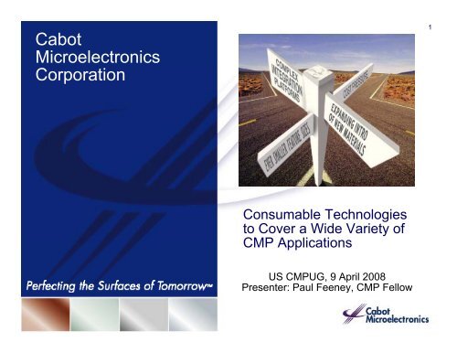
Cabot Microelectronics Corporation - NCCAVS - User Groups
Cabot Microelectronics Corporation - NCCAVS - User Groups
Cabot Microelectronics Corporation - NCCAVS - User Groups
- No tags were found...

You also want an ePaper? Increase the reach of your titles
YUMPU automatically turns print PDFs into web optimized ePapers that Google loves.
Why Do We Need New CMP Applications?3• New CMP applications arise when continuous improvement ofconsumables and equipment are not sufficient• New applications are driven by smaller dimensions– Requirements for a given CMP process get tougher• Step function in performance needed• Need to optimize away from general purpose consumables– IC integration changes with each new advanced node• New and more complex structures t drive new combinations ofexisting materials• Increased complexity leads to segmentation of requirements• New materials required to get chip performance and yield– Benefits of CMP spilled over into DRAM and NVRAM/flash• Accelerated by performance requirements and falling CMP CoO©2008 <strong>Cabot</strong> <strong>Microelectronics</strong> <strong>Corporation</strong>
ITRS 2007 Planarization Applications4First tYear of fICP Production2007200820092010201120122013201420152016201720182019202020212022DRAM 1/2 Pitch65nm 57nm 50nm 45nm 40nm 35nm 32nm 28nm 25nm 22nm 20nm 18nm 16nm 14nm 13nm 12nmMAJOR APPLICATIONSDielectricsShallow trench isolation (STI)[direct]Premetal dielectric (PMD)[target & selective]Interlevel dielectric (ILD)[memory]New applications[i.e. Si nitride]ConductorsPolysilicon [selective& target]Tungsten/buff[contact & via]Copper/barrier[4.0 > κ eff > 2.5]Copper/new barrier[2.7 > κ eff > 2.0]Copper/new barrier[2.2 > κ eff > 1.4]New applications[i.e. new contact]This legend indicates the time during which research, development, and qualification/pre-production should be taking place for the solution.Research RequiredDevelopment UnderwayQualification / Pre-ProductionContinuous Improvement©2008 <strong>Cabot</strong> <strong>Microelectronics</strong> <strong>Corporation</strong>
ITRS 2007 Planarization Consumables5First Year of IC ProductionDRAM 1/2 Pitch200765nm200857nm200950nm201045nm201140nm201235nm201332nm201428nm201525nm201622nm201720nm201818nm201916nm202014nm202113nm202212nmCONSUMABLESFluidsHigh solids slurriesSlurries with low solids/defects/costOptimized formulations fromtunable platformsFluids for chemical enhancedplanarization and ECMPGeneral cleaning solutionsCleaning and buff solutions tailoredto applicationsPadsUrethane pads for new applicationsAbrasive containing padsRange of alternative pads forplanarity/defects/costThis legend indicates the time during which research, development, and qualification/pre-production should be taking place for the solution.Research RequiredDevelopment UnderwayQualification / Pre-ProductionContinuous Improvement©2008 <strong>Cabot</strong> <strong>Microelectronics</strong> <strong>Corporation</strong>
Core Product PipelineAdvanced Solutions Across Applications6Produ uct Evolut tionTungstenW2000SeriesW6000SeriesW7000SeriesAdvancedDielectric / ILD Copper BarrierSemi-SperseSeriesD1300SeriesD3500/D4500SeriesD6700SeriesD8100SeriesC5000SeriesC6000SeriesC7000SeriesC8000SeriesB5200SeriesB6618B7000SeriesB8500SeriesCMPPadsD100EmergingMaterialsAluminumRutheniumNitrideDielectricPolyNoble MetalsMetal Gates© 2008 <strong>Cabot</strong> <strong>Microelectronics</strong> <strong>Corporation</strong>
Tungsten Solutions for Advanced Technologies7X = Benchmark W2000©2008 <strong>Cabot</strong> <strong>Microelectronics</strong> <strong>Corporation</strong>
Edge-Over-Erosion (EOE) Performance8AMATMirra 300 mmEOE is significantly reduced / eliminated withour advanced WIN products©2008 <strong>Cabot</strong> <strong>Microelectronics</strong> <strong>Corporation</strong>
Best-in-Class Defect Performance9©2008 <strong>Cabot</strong> <strong>Microelectronics</strong> <strong>Corporation</strong>
W7300 Best-in-Class Performance Buff Step101 st Step: W2000 1:1 dil700605600500520Plug Device0.16 um/25% density40030020010002916570Erosion (Å)MicroscratchesBuff polish timeSignificant reduction in both defectivity and erosion after W7300 buff step©2008 <strong>Cabot</strong> <strong>Microelectronics</strong> <strong>Corporation</strong>
WIN W7300 B21 / Epic ® D100 ComboErosion Performance – Mirra 200mm11WBApps117: Patterned Plug Oxide ErosionD100 vs IC1000 for WIN W7300-B21 on Ebara400350200 nm Via,25% pattern densityIC1000 PadD100 PadOxide Er rosion (Å/min)300250200150100500Polish ProcessBSP = 225 hPaSCP = 275 hPaRRP = 225 hPaCS = 55 rpmSFR = 150 ml/minPolish time = 60 sPS (IC1000) = 100 rpmPS (D100) = 125 rpm0 5 10 15 20 25 30 35 40 45 50 55Overpolish Time (s)©2008 <strong>Cabot</strong> <strong>Microelectronics</strong> <strong>Corporation</strong>
D100 Improved Defectivity12Defect and Scratch Counts(MIT 854 Mask Patterned Wafers)500400To otal Defects300200100Avg Scratch CountAverage Scratch 18 Count18Average Scratch CountAvg Scratch28Count28D100PadCon. Baseline hardpad> 35% defectivity ect ty reduction by using D100 pads©2008 <strong>Cabot</strong> <strong>Microelectronics</strong> <strong>Corporation</strong>
D100 Longer Pad Life13W Removal Rat te (A/min)6000500040003000200010000253345Con. hard padend of lifeEpic D100 pad life, 2.3xHVM SimulationWafer Run Number** 15 mils groove depthCoO Benefitfrom D100 pad34564594512451545184521452445274530453345364539454245‣Longer pad life confirmedin high volumemanufacturing‣2.5x conventional hard pad‣4x polyurethane impregnatedpolyester pad‣Improved CoO forCustomers©2008 <strong>Cabot</strong> <strong>Microelectronics</strong> <strong>Corporation</strong>
iDIEL D6720and Extension to STI ApplicationsD6720D6720-B1014Abrasive TypeHydrothermal CerianoneChemistryMechanismpH ~ 5.1High Purity (no KOH)Rate Control AdditiveBalanced Chemical& Mechanicalhigh Ox/SiN selectivitySelf-Stopping Additive(SSA)Self-StoppingWhen Added to C2Mean Particle Size~ 90 nmnoneParticle Concentration(POU)Method of Use< 1.0%2X ConcentratedPOU or In-line mixingwithB10orbyitselfitselfnonePOU MixingWith D6720©2008 <strong>Cabot</strong> <strong>Microelectronics</strong> <strong>Corporation</strong>
1.21.0iDIEL D6720Dielectric Removal on ILD PatternSS25E-70% StackD6720-70% Stack15ThicknessNormalized0.80.60.40.220,000A8,000APlanarity Target (SH + ~1500A)>30% Reductionin Polish Time0.00 20 40 60 80 100 120 140 160Polishing Time( sec)D6720 planarizes faster compared to SS25E (polishing time can be shorter)©2008 <strong>Cabot</strong> <strong>Microelectronics</strong> <strong>Corporation</strong>
iDIEL D6720Defectivity on TEOS (Post HF Data)16Defect Comparison Between SS25E and D6720700600N Mean StDev SE MeanD6720-DCN 127 59.7 48.4 4.3SS25E-DCN 468 180.0 87.7 4.1DCN Co ounts (> 0.22 25 um)5004003002001000D6720SS25ED6720 shows 3X reduction in defectivity compared to SS25E©2008 <strong>Cabot</strong> <strong>Microelectronics</strong> <strong>Corporation</strong>
iDIEL D6720POU Mixing of SSA - ILD Test Pattern1717000Re emaining ox xide thicknes ss (A)15000130001100090007000D6720 only = 5490AD6720+B10 (2:1) = 1540A5000POU addition of SSA (B10) to D6720 reduces WID variation >3X10% 30% 50% 70% 90%Pattern Density(%)©2008 <strong>Cabot</strong> <strong>Microelectronics</strong> <strong>Corporation</strong>
iDIEL D8100 vs. iDIEL D6720POU Mixing of SSA - STI Test Pattern (Logic)1816001400Active Ox xide Thickne ess (a)12001000800600400Range ~ 400ARange~790AD6720+B10 (135:65)=90 sec200D8100-A10+B10 (135:65) = 90 sec010 20 30 50 70 90Pattern Density (%)D8100 is better than D6720 for planarity on STI test pattern©2008 <strong>Cabot</strong> <strong>Microelectronics</strong> <strong>Corporation</strong>
350030002500iDIEL D8100 vs. CompetitionSTI Test Pattern (Logic)Competitor 1:3 dil, 120 secSS25 1:1 dil, 60secD8100-A10 + B10 (135:65), 120 s19Step Heigh ht (A)20001500100050000% 20% 40% 60% 80% 100%Pattern DensityD8100 is better than competitor slurry for planarity on STI test pattern©2008 <strong>Cabot</strong> <strong>Microelectronics</strong> <strong>Corporation</strong>
Formulation Design for C810020Functional Group for Cu +2 ComplexationNFFC NFFC NFFC NFFCCu(0) Cu(0) Cu(0)Cu+2Prevents Cu-ion DissolutionCu +2 Cu +2 Cu +2 Cu +2 Cu +2• pH buffered near neutral tobalance oxidation/dissolutionmechanismsBaseline“Dualfunction”AdditiveE-Chem Measurement• Addition of “dual functional”additive for Cu surfacepassivationNFFC = “Novel Film Formation Chemistry”©2008 <strong>Cabot</strong> <strong>Microelectronics</strong> <strong>Corporation</strong>
Next Generation Copper Slurry - iCue ® C810021C8100 Slurry PropertiesCharacteristicC8100Dilution Ratio5X 9 –: 10X1pH (at POU)6 – 6 7ParticleParticle % (at POU)Nano-Colloidal Silica, 50 Silica nm0.50.5%– 1.0%Peroxide Addition1%C8100 Selectivity©2008 <strong>Cabot</strong> <strong>Microelectronics</strong> <strong>Corporation</strong>
Polishing Tool Fault Simulation – iCue ® C8100C8100 - Copper Blanket Defect Pareto vs Tool Hang-up Time300mm AMAT Reflexion221000No Corrosion800600400200SP1 Defect Count053060053060053060053060053060053060Hang Time0No Defect FoundSur urface Particle / ResidueCorrosionNon-CMPScratchRandom Cou ntHangTime053060Note: SP1 Copper Defect Threshold @ 0.25um©2008 <strong>Cabot</strong> <strong>Microelectronics</strong> <strong>Corporation</strong>
D100 Enhanced Planarity231.0099 %‣ Copper Planarity‣ D100 dramaticallyenhances bulk Cuplanarization efficiency‣ D100 delivers improveddishing and erosionperformance100umstep removed(%)hy (A)Topograp1.050.950.900.850.800.7525020015010050100um step PlanarizationD100 padHard padCu Dishing & ErosionEpic ® D100Hard pad(754 Wafers)88 %(800AZ Wafers)0100 um 50 um 10 um 9/1 umErosion©2008 <strong>Cabot</strong> <strong>Microelectronics</strong> <strong>Corporation</strong>
Impact of Wettability on Low-K Rate24Low k Rate Control forRs Variability ReductionNo InhibitorLowk RR (A/m min)SecondGenerationBarrierTailored Inhibitor PackageFirstGenerationBarrierSelectiveInhibitorDual Inhibitor System(BD-1 Specific)Contact Angle©2008 <strong>Cabot</strong> <strong>Microelectronics</strong> <strong>Corporation</strong>
Low K Removal Mechanism25Oxide (hydrolyzed) IncorporatedBlack Diamond SurfaceRR (hybrid) > or = RR (TEOS)Black Diamond(k= 2.7-2.8)Surfactant(BD Inhibitor)Carbon Rich BD Surface(More Hydrophobic)©2008 <strong>Cabot</strong> <strong>Microelectronics</strong> <strong>Corporation</strong>
Verification of Mechanism26©2008 <strong>Cabot</strong> <strong>Microelectronics</strong> <strong>Corporation</strong>
Tailored System Shows Enhanced Rs27Customer Validation of Rs Variability ReductionTailored system wafers have lower SD thancontrol slurry ~ 49% improvement.Overpolish Sensitivity©2008 <strong>Cabot</strong> <strong>Microelectronics</strong> <strong>Corporation</strong>
Drawback of Passivation Chemistry28Suppression of Copper RateCopper ProtrusionRequires Copper Rate Tunability©2008 <strong>Cabot</strong> <strong>Microelectronics</strong> <strong>Corporation</strong>
Copper Rate Control Mechanisms29• Film Formation Control—Rate Suppression.– Inhibitor Level—BTA for example.– Oxidizer Level—Peroxide for example. Validation of Robust Film• Promotion Chemistry.– Complexing Agent.• Structural Control.Enhanced Protection of CopperComplexer + BTAComplexer + BTA+ Gen 2 PackageChosenComplexerIncreasing Hydrophobicity ofCu Complexing AgentYellow chosen based onbalance between FilmFormation and Removal©2008 <strong>Cabot</strong> <strong>Microelectronics</strong> <strong>Corporation</strong>
Increased “Chemical” Cu Rate Reduces Protrusion30Copper DishingData Shown for Model System Performance (unoptimized performance).Latest Performance Shows Dishing < 100 Å, Erosion < 100 Å.©2008 <strong>Cabot</strong> <strong>Microelectronics</strong> <strong>Corporation</strong>
New CMP Applications In FEOL31• Strain Engineering©2008 <strong>Cabot</strong> <strong>Microelectronics</strong> <strong>Corporation</strong>– eSiGe, SiC, Si 3 N 4– Selective and non-selective CMPsteps• Replacement Metal Gate– New Dielectric• Poly/Ox/Nit non-selective• Ox and/or Nit stop on Poly– Metal Damascene• Metal Silicides (NiSi, CoSi,YbSi, etc.)• Al, TaCN, Ru• New Transistor Structures– New Dielectric• Nit stop on OX, Nit/Ox nonselective• Si Replacement• Ge, III/IV (InSb), InGaAs
New CMP Applications In BEOL32• Alternative Liner CMP– Ru, CuMn• Dielectric Cap– Carbides, Nitrides• New Dielectric CMP– Porous Low-k– Air Gap– Low Stress CMP?• Metal wire CMP Otherthan Cu?– Al?• New Contact Metal CMP– Cu, Rh©2008 <strong>Cabot</strong> <strong>Microelectronics</strong> <strong>Corporation</strong>
Additional New IC Related CMP Applications33• DRAM– New capacitor materials: Ru, TiN, Noble Metal?– Advanced poly CMP with high planarity• FLASH– “Reverse” Poly for floating gate• New Non-Volatile Memory– PRAM (GST CMP)– FeRAM (Noble Metal)• 3D IC’s– Through Si Vias– Thinning©2008 <strong>Cabot</strong> <strong>Microelectronics</strong> <strong>Corporation</strong>
Emerging Dielectrics and Exotic Materials34Other FEOLDielectricsNitride/OxideSelectiveNitride/OxideNon selectiveColloidal Silica andCeria PlatformsSiCRuGST©2008 <strong>Cabot</strong> <strong>Microelectronics</strong> <strong>Corporation</strong>
Emerging Metals and Exotic Materials35Noble MetalsTreated AluminaPlatformsAlRu©2008 <strong>Cabot</strong> <strong>Microelectronics</strong> <strong>Corporation</strong>
Developing Finishing Solutions for Multiple Applications36• Prime Silicon Wafer• Flat Panel Displays• Precision Optics• Compound Semiconductor• Healthcare• Defense/Aerospace• Solar Energy• Data Storage/Hard Disk Drive©2008 <strong>Cabot</strong> <strong>Microelectronics</strong> <strong>Corporation</strong>
L8821 Slurry Technology371. Unique complexerstabilizing iH2O2 forconsistent removal rates2. > 10 mg/min removal rateover pad life for greaterthroughput with 7-9 nmsize particles3. ~1A surface roughness(AFM R a )4. Less scratch severity©2008 <strong>Cabot</strong> <strong>Microelectronics</strong> <strong>Corporation</strong>
ESF Opportunities - Examples385-inch FSMAluminum Mirror PolishingProducing the best aluminum mirrorsSingle Point Diamond Turning•Grating effect due to turning marks•Limited to > 50A rms•Use limited to narrow frequency rangeESF Polishing processNo grating effectAchieve < 15A rmsEnable use in wide frequency rangeSilicon Carbide PolishingEnabling higher rateCMC vs. Competition©2008 <strong>Cabot</strong> <strong>Microelectronics</strong> <strong>Corporation</strong>ESF Gen I - commercialized2 X rate vs. PORAchieve 1 A rms reliablyESF Gen II – In development10 X rate vs. PORAchieve 1 A rms reliablyR R (nm/hr)2000150010005000PennSt.Univ.Fla.CollsilicaESFGen IESFGen II
Summary39•Growing number of CMP applications drivesstrong need for consumables innovation•Innovation being achieved to support IC needs•Technology being extended outside of IC’s©2008 <strong>Cabot</strong> <strong>Microelectronics</strong> <strong>Corporation</strong>
<strong>Cabot</strong><strong>Microelectronics</strong><strong>Corporation</strong>40Perfectingthe Surfacesof fTomorrow