Manual - Zephyr
Manual - Zephyr
Manual - Zephyr

You also want an ePaper? Increase the reach of your titles
YUMPU automatically turns print PDFs into web optimized ePapers that Google loves.
www.zephyronline.com
SAFETY NOTICE ................................................................. 2-3LIST OF MATERIALS....................................................... 4INSTALLATIONDucting Calculation Sheet....................................... 5Mounting Height & Clearance................................ 6Ducting Options ........................................................... 7 ................................................... 8Mounting the Range Hood ...................................... 9Mounting the Hood and Duct Cover ................... 10Ductless Recirculation .............................................. 11CONTROLS..................................................................................... 12Table of ContentsMAINTENANCECleaning and Installing Filters ............................... 13Lights................................................................................ 14TROUBLESHOOTING................................................................ 15LIST OF PARTS AND ACCESSORIES .............................. 161
READ AND SAVE THESE INSTRUCTIONSwww.zephyronline.comImportant Safety NoticeWARNINGTO REDUCE THE RISK OF FIRE OR ELECTRIC SHOCK, DO NOT USE THIS FAN WITH ANY SOLID-STATE CONTROL DEVICE.WARNINGTO REDUCE THE RISK OF FIRE ELECTRIC SHOCK, OR INJURY TO PERSONS, OBSERVE THE FOLLOWING:a. Use this unit only in the manner intended by the manufacturer, if you have questions, contact the manufacturer.b. Before servicing or cleaning unit, switch power off at service panel and lock panel to prevent power from being switched on accidentally.When the service disconnecting means cannot be locked, securely fasten a prominent warning device, such as a tag, to the servicepanel.CAUTIONFor general ventilating use only. Do not use to exhaust hazardous or explosive materials and vapors. Take care when using cleaningagents or detergents. Suitable for use in household cooking area.WARNINGTO REDUCE THE RISK OF RANGE TOP GREASE FIRE:a. Never leave surface units unattended at high settings. Boilovers cause smoking and greasy spillovers that may ignite. Heat oils slowlyon low or medium settings. d. Use proper pan size. Always use cookware appropriate for the size of the surface element. f. Use high setting on hood only when necessary.g. Don’t leave hood unattended when cooking.h. Always use cookware and utensils appropriate for the type of and amount of food being prepared.WARNINGTO REDUCE THE RISK OF INJURY TO PERSONS IN THE EVENT OF A RANGE TOP FIRE, OBSERVE THE FOLLOWING: b. NEVER PICK UP A FLAMING PAN – You may be burned.c. DO NOT USE WATER, including wet dishcloths or towels – a violent steam explosion will result.d. Use an extinguisher ONLY if:1. You know you have a Class ABC extinguisher, and you already know how to operate it. WARNINGTO REDUCE THE RISK OF FIRE, ELECTRIC SHOCK OR INJURY TO PERSONS, OBSERVE THE FOLLOWING: back-drafting. Follow the heating equipment manufacturer’s guideline and safety standards such as those published by the Nationalthe local code authorities.c. When cutting or drilling into wall or ceiling, do not damage electrical wiring and other hidden utilities.d. Ducted fans must always vent to the outdoors.e. If this unit is to be installed over a tub or shower, it must be marked as appropriate for the application and be connected to a GFIg. NEVER place a switch where it can be reached from a tub or shower.h. Make sure the power is off before installing, wiring or maintenancing.2
WARNINGTO REDUCE THE RISK OF FIRE, USE ONLY METAL DUCTWORK.CAUTIONattics, crawl spaces or garages.OPERATIONand loose clothing.The manufacturer declines all responsibility in the event of failure to observe the instructions given here for installation,maintenance and suitable use of the product. The manufacturer further declines all responsibility for injury due tonegligence and the warranty of the unit automatically expires due to improper maintenance.*NOTE: Please check www.zephyronline.com for revisions before doing any custom work.ELECTRICAL REQUIREMENTSImportant:Observe all governing codes and ordinances.It is the customer’s responsibility: - To assure that the electrical installation is adequate and in conformance with National Electrical Code, ANSI/NFPA 70latest edition* or CSA standards C22.1-94, Canadian Electrical Code, Part 1 and C22.2 No.0-M91 - latest edition** andall local codes and ordinances.ground path is adequate.Do not ground to a gas pipe.Do not have a fuse in the neutral or ground circuit.*National Fire Protection Association Batterymarch Park, Quincy, Massachusetts 02269** CSA International 8501 East Pleasant Valley Road, Cleveland, Ohio 44131-5575This appliance requires a 120V 60Hz electrical supply and connected to an individual properly grounded branch circuitprotected by a 15 or 20 ampere circuit breaker or time delay fuse. Wiring must be 2 wire with ground. Please also refer toElectrical Diagram on product.and install appropriate connector if necessary.Important Safety Notice3
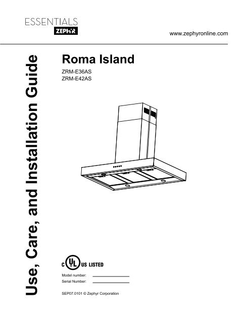
www.zephyronline.comList of MaterialsMODEL: ZRM-E36AS, ZRM-E42AS2 Thick Trim Pieces2 Top Duct Covers 1 Top Support Frame2 Thin Trim Pieces2 Bottom Duct Covers1 Bottom Support Frame1 Hood4 Halogen Light Bulbs (pre-installed)2 Metal Filters (3 - ZRM-E42AS)HARDWARE PACKAGE CONTENTS3 Wire Nuts4 M6*50Wood Screws1 Damper with 2 clips4 ø14 OD / ø6.5 IDWashers4 M5 Wing Nuts10 M4*8Philips Head Screws12 M3*2.5Philips Head Screwsnote: hardware is in metric measurements.No Ducting or Installation Tools Included.4
Duct pieces3-1/ 4” x 10”Rect.,straight7” Round,straight8” Round,straight3-1/ 4” x 10”Rect.90 0elbow3-1/ 4” x 10”Rect.45 0elbow3-1/ 4” x 10”Rect.90 0flat elbow3-1/ 4” x 10”Rect.wall capwith damper3-1/ 4” x 10”Rect.to6” roundtransition3-1/ 4” x 10”Rect.to6” roundtransition90 0 elbow6” Round,90 0 elbowEquivalent numberlength x used = Tot a l1 Ft. x ( ) = Ft.1 Ft. x ( ) = Ft.1 Ft. x ( ) = Ft.15 Ft. x ( ) = Ft.9 Ft. x ( ) = Ft.24 Ft. x ( ) = Ft.30 Ft. x ( ) = Ft.5 Ft. x ( ) = Ft.20 Ft. x ( ) = Ft.15 Ft. x ( ) = Ft.Duct pieces6”- 8” Roundwall capwith damper6”- 8” Round,roof cap6” round to3-1/ 4” x 10”rect.transition6” round to3-1/ 4” x 10”rect.transition90 0 elbow7” or 8”Round,90 0 elbow7” or 8”Round,45 0 elbow7” or 8”Roundwall capwith damper7” or 8”Round,roof cap7” round to3 1/ 4” x 10”rect.transition7” round to3-1/ 4” x 10”rect.transition90 0 elbowEquivalent numberlength x used = Tot a l30 Ft. x ( ) = Ft.30 Ft. x ( ) = Ft.1 Ft. x ( ) = Ft.16 Ft. x ( ) = Ft.15 Ft. x ( ) = Ft.9 Ft. x ( ) = Ft.30 Ft. x ( ) = Ft.30 Ft. x ( ) = Ft.8 Ft. x ( ) = Ft.23 Ft. x ( ) = Ft.Installation – Ducting Calculation Sheet6” Round,45 0 elbow9 Ft. x ( ) = Ft.Subtotal column 2 =Ft.Subtotal column 1 =Ft.Subtotal column 1 =Ft.Total ductwork =Ft.Maximum Duct Length: For satisfactory air movement,the total duct length of a 3 1/ 4” x 10” rectangular 6” or 7”diameter round duct should not exceed 100 equivalent feet.5
www.zephyronline.comInstallation – Mounting Height & ClearanceDUCTINGmin. ducted 28”min. recirc. 32“max. 39”min. 28”max. 36”min. ducted 92” (7’8“)min. recirc. 96” (8’)max. 111” (9’3”)Note: Bottom duct covers may be cut down by 4” to expose top duct cover louver holes.This may be necessary if the customer is recirculating the hood, has an 8’ ceiling andwants the hood mounted between 29 - 32 inches above the cooking surface.A minimum of 6” round or 3-1/4 x 10” rectangularAlways use rigid type metal ducts only. FlexibleUse calculation worksheet to compute total ductwork.ALWAYS, when possible, reduce the number oftransitions and turns. If a long duct run is required,increase duct size from 6” to 7” or 8”.If turns or transitions are required: Install as faraway from opening and as far apart, between 2,as possible.4”36”Minimum mount height between range top to hoodbottom should be no less than 28”.Maximum mount height should be no higher than36”.It is important to install the hood at the propermounting height. Hoods mounted too low couldmounted too high will be hard to reach and willIf available, also refer to range manufacturer’sheight clearance requirements and recommendedhood mounting height above range. Always checkyour local codes for any differences.Mounting Height (Recirculating)Minimum Ceiling Height 8’. Hood mounted 28”Maximum Ceiling Height 9’3”. Hood mounted 36”Mounting Height (Ducted)Duct cover extension kit available for ceilingheights up to 12 feet. Turn to page 16 for partnumber and ordering information.DAMAGE-SHIPMENT / INSTALLATION:• Please fully inspect unit for damage beforeinstallation.• If the unit is damaged in shipment, return theunit to the store in which it was bought forrepair or replacement.• If the unit is damaged by the customer, repairor replacement is the responsibility of thecustomer. be made by arrangement between customerand installer.6
WARNING FIRE HAZARDNEVER exhaust air or terminate duct work into spaces between walls, crawl spaces, ceiling, attics or garages.All exhaust must be ducted to the outside, unless using the recirculating option.Use single wall rigid Metal ductwork only.Some Ducting OptionsRoof Pitch w/Flashing & Capside wall capw/ gravity damperInstallation – Ducting OptionsSoffit or crawl spaceductlessrecirculating7
www.zephyronline.comInstallation – 11 5/8”4 1/2”Front of Hood14”(blower housing)36” or 42” 27”Top of Hood(blower housing)C/Lø5 7/8”electricalK/O1 5/8”3”min. ducted 28”min. recirc. 32”max. 39”4”10 3/4”3/4”7 1/8”Side of Hood12”Top Support Frame(ceiling bracket)12 3/8”10 1/8”8 3/4”7 7/8”1/4”FRONTFRONT1 1/8”8
Ceiling JoistsWood BlockingTop Support FrameBottom Support FrameHoodFront123456Installation – Mounting the Hood!CAUTION: At least two installers arerequired due to the weight and size of thehood. minimum 2 x 42. Fasten top support frame to desired location on ceiling using 4 2” wood screws with washers. The widersection of the support bracket faces the front of the hood.3. Determine height requirement and secure bottom support frame to top support frame by using 8 M4*72 on each angle bracket4. Lift hood and align the locking tabs on top of hood with the 3 tab cut-outs on bottom of support frame.Make sure the 4 threaded posts on top of the hood pass through the holes on bottom support frame.Slide hood forward to lock into place.5. Secure hood to bottom support frame by fastening 4 wing-nuts over the 4 threaded corner posts on top ofhood body.6. Install damper, duct work and electrical. If using hood in recirculating mode you must install the airdiverter plate before assembling the duct covers. Turn to page 11 for instructions.!WARNING: Electrical wiring must be done by a qualified person(s) inaccordance with all applicable codes and standards. This range hood must beproperly grounded. Turn off electrical power at service entrance before wiring.9
www.zephyronline.comInstallation – Mounting the Hood and Duct CoverTop Support FrameTop Duct CoversBottom Duct CoversBottom Support Frame9781110Thick Trim PieceThin Trim Piece With louver holes3 on eachsideLarger screw holes on the duct cover lip should overlapthe smaller holesdown to hide louvered holes.8. Secure top duct covers to top of support frame using 2 M4*7 screws.9. Assemble bottom duct covers over top duct covers and support frame. Use 6 M3*2.5 screws3 on each sideLarger screw holes on the duct cover lip shouldoverlap the smaller holes1 on each side11. The top duct covers may be shorter than the bottom duct covers. It may be necessary to measureand cut the 2 thick trim pieces before installing them into left and right seams of top duct covers.1 on each side10
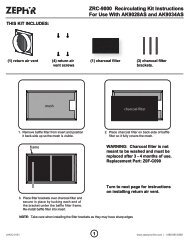
Ductless recirculating is intended for applications where an exhaust duct work is not possible to be installed.When converted, the hood functions as a recirculating hood rather than an exhaust hood. Fumes and exhaustcirculated back within the home.We recommend to ALWAYS exhaust air outside of the home by employing existing or installing new ductis not possible should you recourse to converting the hood into a recirculating hood.Filter set. Order according to its Part number below. The standard Metal Filters are intended to capturecirculation.RECIRCULATING KIT (REQUIRED IF NO DUCTING IS USED)Hood Model Part No. Filters in Pkg.ZRA-E36AS ZRC-0150 2ZRA-E42AS ZRC-0151 31. Assemble mounting brackets and plastic collar onto airdiverter plate as shown in the image to the right. Secureair diverter plate to top support frame using 4 screws.Air diverter openings should face the louver holes of thetop duct cover. Run 6” ducting from top of hood to plasticcollar on air diverter plate and seal with aluminum ducttape.Note: Damper is not necessary when using hood inrecirculating mode. Installation – Ductless RecirculationCharcoal Filter Dimensions:9in x 6 3/8in228mm x 162mm11
www.zephyronline.comControlsBlower OffLights On/OffBlower On/Speed SelectionBlower OffThe blower will be switched off by pressing:Blower On/Speed SelectionSwitch blower on and select speeds 1 - 3 by pressing:Lights On/OffSwitch lights on and off by pressing:12
SURFACE MAINTENANCE:Clean periodically with hot soapy water and clean cotton cloth. Do not use corrosive or abrasive detergent ,or steel wool/scouring pads which will scratch and damage surface.For heavier soil use liquid degreaser.After cleaning it is recommended that you use non-abrasive stainless steel polish/cleaners, to polish and buffout the stainless luster and grain. Always scrub lightly, with clean cotton cloth, and with the grain.Metal Filtersnot be replaced on a regular basis but are required to be kept clean.Filters should be cleaned after every 30 hours of use or once a month.Remove and clean by hand or in dishwasher on low heat. Spray degreasing detergent and leave to soak ifheavily soiled.Replacing Metal Filtersprolonged use, replace with following partnumber:Hood Model: Part No. Qty. to Order.ZRM-E36AS 50200018 2ZRM-E42AS 50200018 3or broken mesh or damaged frame.Metal Filter Dimensions:15 3/4in. x 11in.400mm x 279mmMaintenance – Cleaning and Installing Filters13
www.zephyronline.comMaintenance – LightsREPLACING LIGHT BULBSCAUTION: Light bulb becomes extremely hot when turned on.DO NOT touch bulb until switched off and cooled. Touching hot bulbs could cause serious burns.Make sure all power is turned off and bulbs are not hot.stops and falls out.the bulb or use a rubber/latex glove and turn counter clockwise.For <strong>Zephyr</strong> part numbers please turn to page 16 of the manual.14
TROUBLESHOOTING PROCEDURES FOR ROMAIssue Cause What to doAfter installation,the unit doesn’twork.Light works,but motor is notturning.The unit isvibrating.The motor isworking, but thelights are not.The hood isnot venting outproperly.Metal Filter isvibrating.1. The power source is not turned ON. 1. Make sure the circuit breaker and the unit’spower is ON.2. The power line and the cable locking connectoris not connecting properly.3. The switch board and control board wirings aredisconnected.2. Check the power connection with the unit isconnected properly.3. Make sure the wirings between the switchboard and control board are connectedproperly.4. The switch board or control board is defective. 4. Change the switch board or control board.1. The motor is defective, possibly seized. 1. Change the motor.2. The thermally protected system detects if themotor is too hot to operate and shuts the motordown.2. The motor will function properly after thethermally protected system cool down.3. Damaged capacitor. 3. Change the capacitor.4. The switch board or control board is defective. 4. Change defective part.1. The motor is not secure in place. 1. Tighten the motor in place.2. Damaged blower wheel. 2. Replace the blower.3. The hood is not secured in place. 3. Check the installation of the hood.4. The switch board or control board is defective. 4. Change defective part.1. Defective halogen bulb. 1. Change the halogen bulb.2. The light bulb is loose. 2. Tighten the light bulb.1. The hood might be hanging to high from thecook top.2. The wind from the opened windows or openeddoors in the surrounding area are affecting theventilation of the hood.1. Adjust the distance between the cook top andthe bottom of the hood within 28” and 36”range.2. Close all the windows and doors to eliminate3. Blockage in the duct opening or ductwork. 3. Remove all the blocking from the duct work orduct opening.4. The direction of duct opening is against the wind. 4. Adjust the duct opening direction.5. Using the wrong size of ducting. 5. Change the ducting to at least 6” or higherfor the internal blower and 8” or higher for theexternal blower. Troubleshooting15
www.zephyronline.comList of Parts and AccessoriesDESCRIPTIONPART#Replacement Parts Optional AccessoriesRecirculating Kit, ZRM-E36ASZRC-0150Recirculating Kit, ZRM-E42ASZRC-0151 Duct Cover Extension KitZ1C-00RMTo order parts, visit us online at http://store.zephyronline.com or call us at 1.888.880.836816
Limited WarrantySTAPLE YOUR RECEIPT HEREProof of the original purchasedate is needed to obtainservice under warrantyTO OBTAIN SERVICE UNDER WARRANTY OR FOR ANY SERVICE RELATED QUESTIONS, please call:1-888-880-8368<strong>Zephyr</strong> Corporation (referred to herein as “we” or “us”) warrants to the original consumer purchaser (referred to hereinas “you” or “your”) of <strong>Zephyr</strong> products (the “Products”) that such Products will be free from defects in materials or workmanshipas follows:Two Year Limited Warranty for Parts: For two years from the date of your original purchase of the Products, we willprovide, free of charge, Products or parts to replace those that failed due to manufacturing defects. We may choose, inour sole discretion, to repair or replace parts before we elect to replace the Products.One Year Limited Warranty for Labor: For one year from the date of your original purchase of the Products, we willprovide, free of charge, the labor cost associated with repairing the Products or parts to replace those that failed due tomanufacturing defects. After the first year from the date of your original purchase, you are responsible for all labor costsassociated with this warranty.Warranty Exclusions: This warranty covers only repair or replacement, at our option, of defective Products or partsand does not cover any other costs related to the Products including but not limited to: (a) normal maintenance andservice required for the Products and consumable parts such as light bulbs, metal and carbon filters and fuses; (b) anyProducts or parts which have been subject to freight damage, misuse, negligence, accident, faulty installation or installationcontrary to recommended installation instructions, improper maintenance or repair (other than by us); (c) commercialuse of the Products or use otherwise inconsistent with its intended purpose; (d) natural wear of the finish of the Productsor wear caused by improper maintenance, use of corrosive and abrasive cleaning products, pads, and oven cleanerproducts; (e) chips, dents or cracks caused by abuse or misuse of the Products; (f) service trips to your home to teachyou how to use the Products; or (g) damage to the Products caused by accident, fire, floods or act of God. If you areoutside our service area, additional charges may apply for shipping costs for warranty repair at our designated servicelocations and for the travel cost to have a service technician come to your home to repair, remove or reinstall the Products.After the first year from the date of your original purchase, you are also responsible for all labor costs associatedwith this warranty.Limitations of Warranty. OUR OBLIGATION TO REPAIR OR REPLACE, AT OUR OPTION, SHALL BE YOUR SOLEAND EXCLUSIVE REMEDY UNDER THIS WARRANTY. WE SHALL NOT BE LIABLE FOR INCIDENTAL, CONSE-QUENTIAL OR SPECIAL DAMAGES ARISING OUT OF OR IN CONNECTION WITH THE USE OR PERFORMANCE OFTHE PRODUCTS. THE EXPRESS WARRANTIES IN THE PRECEDING SECTION ARE EXCLUSIVE AND IN LIEU OFALL OTHER EXPRESS WARRANTIES. WE HEREBY DISCLAIM AND EXCLUDE ALL OTHER EXPRESS WARRAN-TIES FOR THE PRODUCTS, AND DISCLAIM AND EXCLUDE ALL WARRANTIES IMPLIED BY LAW, INCLUDINGTHOSE OF MERCHANTABILITY AND FITNESS FOR A PARTICULAR PURPOSE. Some states or provinces do notallow limitations on the duration of an implied warranty or the exclusion or limitation of incidental or consequential damages,so the above limitations or exclusions may not apply to you. To the extent that applicable law prohibits the exclusionof implied warranties, the duration of any applicable implied warranty is limited to the same two-year perioddescribed above. Any oral or written description of the Products is for the sole purpose of identifying the Products andshall not be construed as an express warranty. Prior to using, implementing or permitting use of the Products, you shalldetermine the suitability of the Products for the intended use, and you shall assume all risk and liability whatsoever inconnection with such determination. We reserve the right to use functionally equivalent refurbished or reconditionedparts or Products as warranty replacements or as part of warranty service. This warranty is not transferable from theoriginal purchaser and applies in the United States and Canada.To Obtain Service Under Limited Warranty: To qualify for warranty service, you must: (a) notify us at the address ortelephone number stated below within 60 days of the discovery of the defect; (b) give the model number and part identificationnumber and serial number; and (c) describe the nature of any defect in the Product or part. At the time of therequest for warranty service, you must present evidence of your proof of purchase and proof of the original purchasedate. If we determine that the warranty exclusions listed above apply or if you fail to provide the necessary documentationto obtain service, you will be responsible for all shipping, travel, labor and other costs related to the services.<strong>Zephyr</strong> Corporation, Service Department, 395 Mendell Street, San Francisco, CA 94124 1-888-880-8368APR08.0101