manual sealless steel strapping tool model a337 ... - Acme Packaging
manual sealless steel strapping tool model a337 ... - Acme Packaging
manual sealless steel strapping tool model a337 ... - Acme Packaging

You also want an ePaper? Increase the reach of your titles
YUMPU automatically turns print PDFs into web optimized ePapers that Google loves.
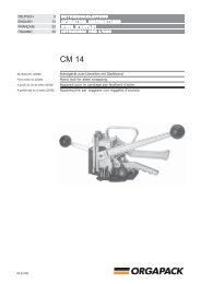
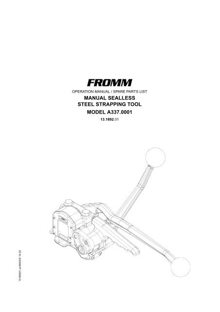
OPERATION MANUAL / SPARE PARTS LISTMANUAL SEALLESSSTEEL STRAPPING TOOLMODEL A337.000113.1892.0113189201.en/MAS/© 10.02
INDEXPAGE1 SAFETY INSTRUCTIONS 22 WARRANTY CONDITIONS AND LIABILITY 43 APPROPRIATE USE 44 TECNICAL DATA 45 CHART OF TYPES A337.0001 56 OPERATION LEVERS 67 OPERATION 68 SPARE PARTS LIST 13.1892.01 109 SEAL CONTROL 1210 SEAL ADJUSTMENT 1311 CLEANING 1312 EXCHANGE OF WEARING PARTS 141 SAFETY INSTRUCTIONSRead these instructions carefully. Failure to follow these instructions can result in severe personal injury.Eye injury hazardFailure to wear safety glasses with side shields can result in severe eye injury or blindness. Always wearsafety glasses with side shields which conform to ANSI Standard Z87.1.OperationTool must not be used by persons not properly trained in their use. Before tensioning strap, read andunderstand the <strong>tool</strong> operating instructions. Failure to follow the operating instructions or improper loadpositioning could result in strap breakage.Become familiar with your <strong>tool</strong> and keep fingers away from areas that can pinch or cut.2
JointsYou are fully responsible to review the joints made by your <strong>tool</strong>. Become familiar with the seal control and sealadjustment described in this operation <strong>manual</strong>. Misformed joints may not secure the load and could causeserious injury. Never handle or ship any load with improperly formed joints.Dispensing strapOnly dispense strap from a dispenser specifically designed for strap.Tuck strap end back into dispenser when not in use.Protective glovesWhen handling strap, always wear protective gloves.Strap warningsNever use strap as a means of pulling or lifting loads. Failure to follow these warnings can result in severepersonal injury.Strap breakage hazardImproper operation of the <strong>tool</strong>, excessive tensioning, using strap not recommended for this <strong>tool</strong> or sharpcorners on the load can result in a sudden loss of strap tension or in strap breakage during tensioning, whichcould result in the following:• A sudden loss of balance causing you to fall.• Both <strong>tool</strong> and strap flying violently towards your face.Note as follows:• If the load corners are sharp, use edge protectors.• Place the strap correctly around a properly positioned load.• Positioning yourself in-line with the strap, during tensioning and sealing, can result in severe personalinjury from flying strap or <strong>tool</strong>. When tensioning or sealing, position yourself to one side of the strap andkeep all bystanders away.• Use the correct strap quality, strap width, strap gauge and strap tensile strength recommended in this<strong>manual</strong> for your <strong>tool</strong>. Using strap not recommended for this <strong>tool</strong> can result in strap breakage duringtensioning.Cutting tensioned strapWhen cutting <strong>strapping</strong>, use the proper <strong>strapping</strong> cutter and keep other personnel and yourself at a safedistance from the strap. Always stand to side of the strap, away from the direction the loosened strap end willfly. Use only cutters designed for strap and never hammers, pliers, hacksaws, axes, etc.Fall hazardKeep your working area tidy. Untidiness of your working area may cause a risk of injury. Maintaining improperfooting and/or balance when operating the <strong>tool</strong> can cause you to fall. Before tensioning and especially inelevated areas, always establish good balance. Both feet should be securely placed on a flat, solid surface,especially when working in elevated areas. Do not use the <strong>tool</strong> when you are in an awkward position.Pay attention to the rules and regulations for preventions of accident which are valid for the work place.Tool hazardsA well maintained <strong>tool</strong> is a safe <strong>tool</strong>!Check <strong>tool</strong> regularly for broken or worn parts. Do not operate a <strong>tool</strong> with broken or worn parts.Never modify any <strong>tool</strong>. Modification can result in severe bodily injury.3
2 WARRANTY CONDITIONS AND LIABILITYFROMM Holding AG warrants all its <strong>strapping</strong> <strong>tool</strong>s and machine heads during a period of 90 days from thedate of sale. The warranty includes all deficiencies clearly resulting from poor manufacturing or faulty materials.Damage claims as a result of production shutdowns and claims for damage to persons and to propertyresulting from warranty deficiencies cannot be asserted by the customer.The warranty excludes:• wearing parts• deficiencies resulting from improper installing, incorrect handling and maintaining the <strong>tool</strong>• deficiencies resulting from using the <strong>tool</strong> without or with defective security- and safety devices• disregard of directions in the operation <strong>manual</strong>• arbitrary modifications of the <strong>tool</strong>• deficient control of wearing parts• deficient repair works of the <strong>tool</strong>• Use of consumable products not recommended by FROMM Holding AGWe reserve the right to modify the product at any time in order to improve its quality.3 APPROPRIATE USEThe <strong>tool</strong> <strong>model</strong> A337 has been designed to strap packages with <strong>steel</strong> <strong>strapping</strong> exclusively.The warranty / liability excludes:• non appropriate use of the <strong>tool</strong>,• disregard of directions in the operation <strong>manual</strong>,• disregard of control- and maintenance instructions.4 TECNICAL DATADimensions without suspension bracketTool:Package:Length: 430 mm / 16.9" 730 mm / 28.7"Width: 160 mm / 6.3" 230 mm / 9.1"Height: 315 mm / 12.4" 180 mm / 7.1"Weight: 4.45 kg / 9.8 lbs 1.67 kg / 3.8 lbsTensioning force4 KN / 900 lbs (270 N / 60 lbs <strong>manual</strong> force)Sealing forceThe <strong>manual</strong> force required for sealing is approx. 200 N / 45 lbs.Joint strengthApprox. 80% of the strap’s tensile strength.Steel <strong>strapping</strong>Width:Thickness:Quality:9.5 - 20 mm / 3/8 - 3/4" (see chart of types)0.38 - 0.63 mm / .015 - .025" (see chart of types)Fundamentally the A337 allows the use of all current <strong>steel</strong> straps with tensile strengthsranging from 700 to 1100 N/mm 2 / 100 000 - 160 000 psi (see chart of types).Straps with a low breaking elongation are unsuitable.4 A3370001enT1.man
5 CHART OF TYPES A337.0001Item No. Model Strap width Strap thickness13.1850 A337/9.5/0.38-0.50 9.5mm / 3/8" 0.38-0.50mm / .015-.020"13.1860 A337/10/0.38-0.50 10.0mm 0.38-0.50mm / .015-.020"13.1870 A337/12.7/0.38-0.50 12.7mm / 1/2" 0.38-0.50mm / .015-.020"13.1872 A337/12.7/0.50-0.63 12.7mm / 1/2" 0.50-0.63mm / .020-.025"13.1880 A337/13/0.38-0.50 13.0mm 0.38-0.50mm / .015-.020"13.1882 A337/13/0.50-0.63 13.0mm 0.50-0.63mm / .020-.025"13.1890 A337/16/0.38-0.50 16.0mm / 5/8" 0.38-0.50mm / .015-.020"13.1892 A337/16/0.50-0.63 16.0mm / 5/8" 0.50-0.63mm / .020-.025"13.1910 A337/19/0.38-0.50 19.0mm / 3/4" 0.38-0.50mm / .015-.020"13.1912 A337/19/0.50-0.63 19.0mm / 3/4" 0.50-0.63mm / .020-.025"13.1920 A337/20/0.38-0.50 20.0mm 0.38-0.50mm / .015-.020"13.1922 A337/20/0.50-0.63 20.0mm 0.50-0.63mm / .020-.025"AccessoriesItem No. Designation RemarksN4.1411 Hexagon socket screw key Delivered with the machine.A33.0121 Susp. bracket for vertical and horizontal operation To be ordered separately in case of need.A33.0122 Tang for horizontal operation To be ordered separately in case of need.A33.0121VerticalA33.0121HorizontalA33.0122HorizontalA3370001enT1.man5
6 OPERATION LEVERSTensioning handleSealing leverRocker7 OPERATIONFeeding the <strong>strapping</strong> around thepackageThe <strong>strapping</strong> is fed around the package in thedirection as shown in the illustration. The <strong>strapping</strong>end is held tightly with the left hand and pulled firmlytowards the operator with the right hand.Loading the <strong>strapping</strong>The rocker is raised with the right hand. The left handinserts the two straps lying precisely upon anotherinto the <strong>tool</strong> until they hit the strap stops.The lower strap end must slightly protrude the end ofthe base plate.Be certain that the <strong>strapping</strong> is held by the strap guide.6 A3370001enT1.man
Tensioning the <strong>strapping</strong>The <strong>tool</strong> is held tightly with the left hand being placed on thesealing lever. The tensioning handle is now moved forward andbackward with the right hand until the desired tension isattained.Sealing the <strong>strapping</strong>The sealing lever is moved forward using the left hand until ithits the stop. The lever is then moved back to its initial position.When sealing, the right hand absorbs the sealing force byholding the tensioning handle.Releasing the <strong>tool</strong>Hold the cut off strap end with the left hand, lift the rocker withthe right hand and push the <strong>tool</strong> from the applied strap to theright.Releasing the feed wheel after faulty operationIf the feed-wheel is jammed with the strap and the rocker cannotbe released the following procedure is necessary to remove the<strong>strapping</strong> from the <strong>tool</strong>:• loosen screws N1.1571 and N11.1126.N1.1571 = 90 NmN1.1571 = 110 Nm• lift rocker and remove <strong>steel</strong> <strong>strapping</strong> from the <strong>tool</strong>.• retighten screws N1.1571 and N11.1126 with a torque of90 resp. 110 Nm (800 resp. 970 lbs).N11.1126 = 90 NmRockerA3370001enT1.man7
A12 3N1.1807N1.1571A33.7028A33.7023A33.0114BA33.7018A33.7001A33.5121Œ A33.5122Œ N3.3160 A33.5117A33.0105N2.2138Œ A33.7017A33.0115Œ N3.3160A33.7003N1.3513N2.2109CA33.7021Œ A33.7019A33.5118ŒN3.3160A33.5107N2.2110N4.9152A33.7016A33.7006N2.4902A33.5113A33.7020 ŒA33.5114N2.2147N1.6203N41.9128N1.6503N1.1806N1.1304DN1.1912A33.7032A33.5127A33.0117A38.3210A33.7103EN3.2348N1.6220N2.2172N1.110613189201.z
8 SPARE PARTS LIST 13.1892.0113.1892.01 A337/16/0.50-0.63 A337.0001.01 29.02.00Item-No. in group Pcs. Description Dimension Field[A33.0105] 1 BEARING PICK-UP ATTACHMENT B2[A33.0114] 1 SEALING HOUSING A4[A33.0115] 1 DIE AND CUTTER SUPPORT B2[A33.0116] 1 ROCKER C6[A33.0117] 1 END COVER D3[A33.0118] 1 TENSION HANDLE C7[A33.0120] 1 SEALING HANDLE A5A33.3110 2 TENSIONING PAWL C5A33.3124 2 RING HALF D6A33.5107 * 1 PUNCH C3A33.5113 * 1 DIE HALF C3A33.5114 * 1 DIE HALF C3A33.5117 1 ROLLER B3A33.5118 1 PARALLEL PIN C2A33.5121 1 EYE B2A33.5122 A33.0105 1 BEARING PICK-UP ATTACHMENT B2A33.5127 1 EJECTOR SCREW D4A33.5224 2 SPACER RING D5[A33.7001] A33.0114 1 SEALING HOUSING B4A33.7003 A33.0115 1 DIE AND CUTTER SUPPORT B3A33.7006 1 BASE PLATE C4A33.7012 1 HOLDER C5A33.7016 * 1 CUTTER C3A33.7017 2 GUIDE GIB B3A33.7018 1 ECCENTRIC SHAFT B3A33.7019 1 GUIDE GIB C2A33.7020 1 GUIDE GIB C2A33.7021 1 SIDE PLATE C2A33.7022 1 COVER DISK A5A33.7023 1 EJECTOR A3A33.7028 1 STRAP STOP A3A33.7032 1 EJECTOR D4A33.7033 A33.0120 1 SEALING HANDLE A5[A33.7101] A33.0116 1 ROCKER C7A33.7103 A33.0117 1 END COVER D3A33.7104 A33.0118 1 TENSION HANDLE D7[A33.7108] 1 TENSION SHAFT D5A33.7114 * 1 TENSIONING WHEEL D5A33.7120 1 STRAP GUIDE D4A38.3129 * 1 GRIPPER C5A38.3210 1 PIVOT PIN D3A43.1207 1 DISK D7N11.1126 1 SCREW M10 X 1 X 39 C4N1.1106 1 SCREW M6 X 20 E2N1.1166 A33.0116 1 SCREW M5 X 30 C7N1.1304 2 SCREW M3 X 8 C4N1.1571 2 HEXAGON SCREW M12 X 1.25 X 90 A4N1.1806 4 SCREW M4 X 10 C3N1.1807 5 SCREW M5 X 12 A3+N1.1912 6 FLAT HEAD SCREW M5 X 16 D1N1.2135 1 COUNTERSUNK SCREW M5 X 12 A5[ ] = Group * = Wearing parts10 13189201.een.fm
13.1892.01 A337/16/0.50-0.63 A337.0001.01 29.02.00Item-No. in group Pcs. Description Dimension FieldN1.3513 1 SOCKET SET SCREW M10 X 40 B4N1.6203 2 SPRING LOCK WASHER M3 C4N1.6207 A33.0116 1 SPRING LOCK WASHER M5 C7N1.6220 1 SPRING LOCK WASHER M6 E3N1.6326 2 SUPPORTING DISK 30 X 42 X 2.5 C6+N1.6503 6 SAFETY WASHER M5 C2N2.1122 1 SECURITY RING E21 D7N2.2109 2 PARALLEL PIN 8 m6 X 30 B4N2.2110 A33.0115 2 PARALLEL PIN 4 m6 X 10 C3N2.2138 1 PARALLEL PIN 4 m6 X 12 B4N2.2147 1 PARALLEL PIN 3 m6 X 10 C4N2.2172 A33.0117 2 PARALLEL PIN 5 m6 X 30 E3N2.4902 2 HAMMER HEAD BOLT 1.85 X 4.76 C1N2.4906 A33.0120 1 HAMMER HEAD BOLT 5,31 X 12,7 A5N2.5154 2 PRESSURE SPRING 0.45 X 3.9 X 7 C5N2.5215 1 PRESSURE SPRING 2,25X11,75X125 B6N3.2348 A33.0117 1 NEEDLE CASE E4N3.2606 A33.0117 1 PACKING RING D4N3.2904 1 PIN 4 X 8 B4N3.3160 A33.0105 1 SLIDE-BEARING B2N3.3160 A33.0115 2 SLIDE-BEARING B2+N3.3164 A33.0114 1 SLIDE-BEARING B4N3.4507 A33.0116 1 NEEDLE FREE WHEELING E6N41.9128 1 ADHESIVE LABEL C2N4.1116 A33.0118 1 GRIP BALL C7N4.1116 A33.0120 1 GRIP BALL B6N4.1411 1 SOCKET WRENCH 5 mm --N4.9152 1 NUMBER PLATE A337 C1[ ] = Group * = Wearing parts13189201.een.fm11
9 SEAL CONTROLA regular control of the seal is necessary. The seal can be checked visually and the person controlling caneasily judge the quality of the seal. When checking the seal the following illustrations must be compared.Correct sealA correct seal must be conform to the illustration. This means that the depth with which the upper strap hooksinto the lower one must be 1 – 1.5 mm ( 0.039 – 0.059”) in min. and must not exceed 2 mm (0.079”). The upperstrap must be sheared clean and the cutter must not leave scratch marks on the lower strap.Incorrect seal (the sealing mechanism is adjusted too high)This stamped seal is not deep enough and the upper strap is not sheared.The tensile strength of this seal isinsufficient and the <strong>strapping</strong> must be taken away from the package. The <strong>tool</strong> must be readjusted immediately(see SEAL ADJUSTMENT).Incorrect seal (the sealing mechanism is adjusted too low)This stamped seal is too deep and the lower strap is scratched by the cutter. Although the tensile strength ofthis seal is sufficient the <strong>strapping</strong> must be taken away from the package because of the scratched lower strap.The <strong>tool</strong> must be readjusted immediately (see SEAL ADJUSTMENT).12 A3370001enT2.man
10 SEAL ADJUSTMENTThe sealing- and cutting depth of the sealing mechanism and the cutter can be adjusted by using a hexagonkey N4.1411 (size 5 mm) and turning the adjustment screw infinitely variable. The hexagon key N4.1411 issupplied with the <strong>tool</strong>.Sealing depth is excessiveTurning the adjustment screw in a clockwise direction reduces the sealing depth.Sealing depth is insufficientTurning the adjustment screw in a counter clockwise direction increases the sealing depth.N4.141111 CLEANINGIn case of heavy dirt and when painted straps are used the punch, dies, gripper and feed-wheel must becleaned regularly.Normally it is sufficient to blow out the parts with the help of an air gun.A3370001enT2.man13
12 EXCHANGE OF WEARING PARTSExchange of the feed wheel and the gripper• Disassemble cylinder screw in the end plate.• Lift the rocker and remove end plate, strap guide, supporting disk and feed wheel from the tension shaft.• Unscrew holder and remove it together with the gripper from the base plate.• Fitting in opposite order.Feed wheelSupporting diskStrap guideEnd plateRockerGripperHolderImportant!The fastening screw for the holder has to be secured with LOCTITE 222.Observe assembling position of the feed wheel14 A3370001enT2.man
Exchange of the punch, the dies and the cutter• Disassemble the ejector and the ejector screw.• Unscrew the strap stop and pull the upper ejector together with the strap stop out of the <strong>tool</strong>.• Unscrew the side plate and disassemble both guide gibs.• Slightly lift the sealing lever and remove bearing pick-up attachment, link and the die- and cutter piston fromthesealingbody.• Clean all parts and replace the worn ones.• Fitting in opposite order.Strap stop with upper ejectorDieandcutterpistonwithlinkDies left and rightBearing pick-up attachmentGuide gibsCutterPunchEjectorEjector screwImportant!Bearing areas and guides have to be greased.The fastening screws for the punch and the dies have to be secured with LOCTITE 222.A3370001enT2.man15
16 A3370001enT2.man