Logisim Tutorial
Logisim Tutorial
Logisim Tutorial
- No tags were found...

You also want an ePaper? Increase the reach of your titles
YUMPU automatically turns print PDFs into web optimized ePapers that Google loves.
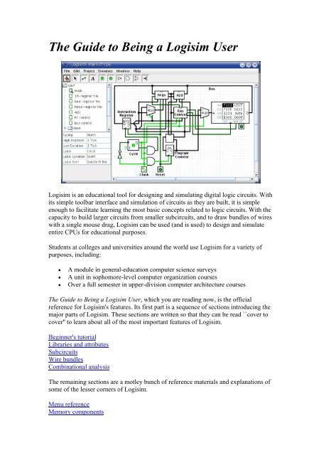
Next: Step 2: Adding wiresStep 1: Adding gatesRecall that we're trying to build the following circuit in <strong>Logisim</strong>.Building a circuit is easiest by inserting the gates first as a sort of skeleton forconnecting wires into the circuit later. The first thing we're going to do is to add thetwo AND gates. Click on the AND tool in the toolbar ( , the next-to-last tool listed).Then click in the editing area where you want the AND gates to go. Be sure to leaveplenty of room for stuff on the left.Notice the five dots on the left side of the AND gate. These are spots where wires canbe attached. It happens that we'll just use two of them for our XOR circuit; but forother circuits, you may find that having more than two wires going to an AND gate isuseful.Now add the other gates. First click on the OR tool ( ); then click where you want it.And select the NOT tool ( ) and put those two gates into the canvas.
I left a little space between the NOT gates and the AND gates; if you want to, though,you can put them up against each other and save yourself the effort of drawing a wirein later.Now we want to add the two inputs x and y into the diagram. Select the input pin ( ),and place the pins down. You should also place an output pin ( ) next to the ORgate's output. (Again, though I'm leaving a bit of space between the OR gate and theoutput pin, you might choose to place them right next to each other.)If you decide you don't like where you placed something, then you can right-click (orcontrol-click) anything in the canvas to view a pop-up menu. Choose Delete. You canalso rearrange things using the select tool ( ).Next: Step 2: Adding wiresNext: Step 3: Adding text
Step 2: Adding wiresAfter you have all the components blocked out on the canvas, you're ready to startadding wires. Select the wiring tool ( ). Then start dragging from one position toanother in the canvas area, and a wire will start to appear between the two points.Wires in <strong>Logisim</strong> must be horizontal or vertical. To connect the upper input to theNOT gate and the AND gate, then, I added three different wires.<strong>Logisim</strong> automatically connects wires to the gates and to each other. This includesautomatically drawing the circle at a T T intersection as above, indicating that the wiresare connected.As you draw wires, you may see some blue or gray wires. Blue in <strong>Logisim</strong> indicatesthat the value at that point is ``unknown'', and gray indicates that the wire is notconnected to anything. This is not a big deal temporarily. But by the time you finishyour circuit, none of your wires should be blue or gray. (The unconnected legs of theOR gate will still be blue: That's fine.)If you do have a blue or a gray wire after you think everything ought to be connected,then something is going wrong. It's important that you connect wires to the rightplaces. <strong>Logisim</strong> draws little dots on the components to indicate where wires ought toconnect. As you proceed, you'll see the dots turn from blue to light or dark green.Once you have all the wires connected, all of the wires you inserted will themselvesbe light or dark green.
Next: Step 3: Adding textNext: Step 4: Testing your circuitStep 3: Adding textAdding text to the circuit isn't necessary to make it work; but if you want to showyour circuit to somebody (like a teacher), then some labels help to to communicate thepurpose of the different pieces of your circuit.Select the text tool ( ). You can click on an input pin and start typing to give it alabel. (It's better to click directly on the input pin than to click where you want thetext to go, because then the label will move with the pin.) You can do the same for theoutput pin. Or you could just click any old place and start typing to put a labelanywhere else.Next: Step 4: Testing your circuitNext: User's Guide
Step 4: Testing your circuitOur final step is to test our circuit to ensure that it really does what we intended.<strong>Logisim</strong> is already simulating the circuit. Let's look again at where we were.Note that the input pins both contain 0s; and so does the output pin. This already tellsus that the circuit already computes a 0 when both inputs are 0.Now to try another combination of inputs. Select the poke tool ( ) and start pokingthe inputs by clicking on them. Each time you poke an input, its value will toggle. Forexample, we might first poke the bottom input.When you change the input value, <strong>Logisim</strong> will show you what values travel downthe wires by drawing them light green to indicate a 1 value or dark green (almostblack) to indicate a 0 value. You can also see that the output value has changed to 1.So far, we have tested the first two rows of our truth table, and the outputs (0 and 1)match the desired outputs.
By poking the switches through different combinations, we can verify the other tworows. If they all match, then we're done: The circuit works!To archive your completed work, you might want to save or print your circuit. TheFile menu allows this, and of course it also allows you to exit <strong>Logisim</strong>. But why quitnow?Now that you are finished with tutorial, you can experiment with <strong>Logisim</strong> by buildingyour own circuits. If you want to build circuits with more sophisticated features, thenyou should navigate through the rest of the help system to see what else you can do.<strong>Logisim</strong> is a powerful program, allowing you to build up and test huge circuits; thisstep-by-step process just scratches the surface.Next: User's GuideLibraries and AttributesIn this section, we'll examine how to use the other two major regions of the <strong>Logisim</strong>window, the explorer pane and the attribute table.The explorer paneThe attribute tableTool and component attributesNext: The explorer pane.
The explorer paneLibraries contain components that can be dropped into circuits. They are displayed asfolders in the explorer pane; to access a library's components, you have only todouble-click the corresponding folder. Below, I have opened the Gates library andselected the NAND tool from it. You can see that <strong>Logisim</strong> now stands ready to addNAND gates into the circuit.If you look through the choices in the Gates library, you'll notice that there was noneed for us to develop a XOR circuit earlier: It's built into <strong>Logisim</strong>.When you create a project, it automatically includes the Base and Gates libraries. But<strong>Logisim</strong> includes many other libraries, too: To load one, go to the Project menu, in theLoad Library submenu, and choose Built-in Library.... A dialog box will appearallowing you to choose which libraries you want to add. If you choose Plexers, forexample, then you will be able to add multiplexers, demultiplexers, and decoders.You can load as many libraries as you like.In the Load Library submenu, you can see that <strong>Logisim</strong> has three categories oflibraries.• Built-in libraries are libraries that are distributed with <strong>Logisim</strong>. These aredocumented in the Library Reference.• <strong>Logisim</strong> libraries are projects built within <strong>Logisim</strong> and saved to the disk. Youcan develop a set of circuits in a single project (as described in the Subcircuitssection of this guide) and then use that set of circuits as a library for anotherprojects.• JAR libraries are libraries that are developed in Java but not distributed with<strong>Logisim</strong>. You can download JAR libraries that others have written, or you canwrite your own as described in the JAR Libraries section of this guide.Developing a JAR library is much more difficult than developing a <strong>Logisim</strong>library, but the components can be much fancier, including things likeattributes and interaction with the user. The built-in libraries (other than Base)
were written using the same API as JAR libraries can use, so they aptlydemonstrate the range of functionality that the JAR libraries can support.When loading a JAR library, <strong>Logisim</strong> will prompt you to select the JAR file,and then it will prompt you to type a class name. This class name should beprovided by whoever distributed the JAR file to you.To remove a library, choose Unload Library... from the Project menu. <strong>Logisim</strong> willprevent you from unloading libraries that contain components used in a circuit, thatappear in the toolbar, or that are mapped to a mouse button.Incidentally, a library technically contains tools, not components. Thus, in the Baselibrary you'll find the Poke Tool ( ), the Select Tool ( ), and other tools that don'tcorrespond directly to individual components. Most libraries, though, contain onlytools for adding individual components; all built-in libraries other than the Baselibrary are like this.Next: The attribute table.The attribute tableMany components have attributes, which are properties for configuring how thecomponent behaves or appears. The attribute table is for viewing and displaying acomponent's attribute values.To select which component's attributes you wish to view, click the component usingthe Select tool ( ). (You can also right-click (or control-click) the component andchoose Show Attributes from the popup menu. Also, manipulating a component viathe Poke tool ( ) or the Text tool ( ) will display that component's attributes.)The below screen shot demonstrates what things look like after selecting the upperinput of our XOR circuit and scrolling down to view the Label Font attribute.
Note the pale teal (i.e., light blue) oval surrounding the pin, called a halo: Thisindicates whose attributes are displayed in the attribute table.To modify an attribute value, click on the value. The interface for modifying theattribute will depend on which attribute you are changing; in the case of the LabelFont attribute, a dialog box will appear for selecting the new font; but some attributes(like Label) will allow you to edit the value as a text field, while others (like LabelLocation) will display a drop-down menu from which to select the value.Each component type has a different set of attributes; to learn what they mean, go tothe relevant documentation in the Library Reference.Some components have attribute values that cannot be changed. One example of thisis the AND gate's Gate Size attribute: As soon as you create an AND gate, is size isfixed. If you want an AND gate of a different size, then you'll need to change theattributes for the tool, which we'll discuss next.Next: Tool attributes.Tool attributesEvery tool for adding components to a circuit also has a set of attributes, which areimparted to the components created by the tool, although the components' attributesmay be changed later without affecting the tool's attributes. When you select a tool,<strong>Logisim</strong> will change the attribute table to display that tool's attributes.For example, suppose we want to create smaller AND gates. We've already seen thatan AND gate's Gate Size attribute is not editable. But the Gate Size attribute iseditable for the AND gate tool: To view and edit this attribute, click the tool's icon inthe toolbar (or the explorer pane), and change its Gate Size attribute.
Now, we can delete the two existing AND gates and add two new AND gates in theirplace. This time, they will be narrow. (If you chose to reduce the number of inputs to3, the AND gate would not have vertical extension on the left side. But you'd alsohave to rewire the circuit so that the wires hit the AND gate's left side.)With some tools, the icon reflects some of the attributes' values. One example of thisis with the Pin tool, whose icon faces the same way as its Facing attribute says.The tools in the toolbar each have a separate attribute set from the corresponding toolsin the explorer pane. Thus, even though we changed the toolbar's AND tool to createnarrow AND gates, the AND tool in the Gates library will still create wide AND gatesunless you change its attributes too.In fact, the input pin and output pin tools in the default toolbar are both instances ofthe Base library's Pin tool, but the three attribute sets are different. The icon for thePin tool is drawn as a circle or a square depending on the value of its ``Output?''attribute.<strong>Logisim</strong> provides a handy shortcut for changing the Facing attribute that controls thedirection in which many components face: Typing an arrow key while that tool isselected automatically changes the direction of the component.Next: User's Guide.
SubcircuitsAs you build circuits that are more and more sophisticated, you will want to buildsmaller circuits that you can use multiple times in larger circuits. In <strong>Logisim</strong>, such asmaller circuit that is used in a larger circuit is called a subcircuit.If you're familiar with computer programming, you're familiar with the subprogramconcept (called subroutines, functions, or methods in different languages). Thesubcircuit concept is analogous to the concept in computer programming, and it isused for the same purposes: To break a large job into bite-sized pieces, to save theeffort of defining the same concept multiple times, and to facilitate debugging.Creating circuitsUsing subcircuitsDebugging subcircuits<strong>Logisim</strong> librariesNext: Creating circuits.Creating circuitsEvery <strong>Logisim</strong> project is actually a library of circuits. In its simplest form, eachproject has only one circuit (called "main" by default), but it is easy to add more:Select Add Circuit... from the Project menu, and type any name you like for the newcircuit you want to create.Suppose we want to build a 1x2 multiplexer named "1x2 MUX." After adding thecircuit, <strong>Logisim</strong> will look like this.In the explorer pane, you can now see that the project now contains two circuits,"main", and "1x2 MUX." <strong>Logisim</strong> draws a magnifying glass over the icon of thecircuit currently being viewed; the current circuit name also appears in the window'stitle bar.
After editing the circuit to appear like a 1x2 multiplexer, we might end up with thefollowing circuit.Next: Using subcircuits.Using subcircuitsNow suppose we want to build a 2x4 multiplexer using instances of our 1x2multiplexer. Of course, we would first create a new circuit, which we'll call "2x4MUX." To add 1x2 multiplexers into our circuit, we click the 1x2 MUX circuit oncein the explorer pane to select it as a tool, and then we can add copies of it, representedas boxes, by clicking within the canvas.If you click the 1x2 MUX circuit twice in the explorer pane, then the window wouldswitch to editing the 1x2 MUX circuit instead.After building up the circuit, we end up with the following.
Our circuit for a 2x4 multiplexer uses three copies of the 1x2 multiplexer, each drawnas a box with pins along the side. The pins on this box correspond to the input andoutput pins in the 1x2 MUX circuit. The two pins on the west side of the boxcorrespond to the two pins that face east in the 1x2 MUX circuit; the pin on the box'seast side corresponds to the 1x2 MUX's west-facing pin (which happens to be anoutput pin); and the pin on the box's south side corresponds to the 1x2 MUX's northfacingpin. The order of the two pins on the box's west side correspond to the sametop-down ordering that apears in the subcircuit. (If there were several pins on thebox's north or south side, they would correspond to the same left-right order in thesubcircuit.)If the pins in the subcircuit's layout have labels associated with them, then <strong>Logisim</strong>will display that label in a tip (that is, a temporary text box) when the user hovers themouse over the corresponding location of the subcircuit component. (If you find thesetips irritating, you can disable them via the Project Options window's Canvas tab.)Several other components will display these tips, too: For some of the pins of a builtinflip-flop, for example, hovering over it explains what that pin does.Incidentally, every pin to a circuit must be either an input or an output. Manymanufactured chips have pins that behave as an input in some situations and as anoutput in others; you cannot construct such chips within <strong>Logisim</strong>.
<strong>Logisim</strong> will maintain different state information for all subcircuits appearing in acircuit. For example, if a circuit contains a flip-flop, and that circuit is used as asubcircuit several times, then each subcircuit's flip-flop will have its own value whensimulating the larger circuit.Now that we have the 2x4 multiplexer defined, we can now use it in other circuits.<strong>Logisim</strong> has no limits on how deeply circuits can be nested - though it will object tonesting circuits within themselves!Note: There's nothing wrong with editing a circuit that is being used as a subcircuit;in fact, this is quite common. Be aware, though, that any changes to a circuit's pins(adding, deleting, or moving them) will rearrange them also in the containing circuit.Thus, if you change any pins in a circuit, you will also need to edit any circuits usingit as a subcircuit.Next: Debugging subcircuits.Debugging subcircuitsAs you test larger circuits, you will likely find bugs. To nail down what's goingwrong, exploring what's going on in the subcircuits while running the overall circuitcan help. From viewing the overall circuit, you can do this by bringing up thesubcircuit's popup menu (right-click or control-click its box). Then choose the Viewoption.After choosing this, the view will switch to the subcircuit.
Notice that the pins' values in the subcircuit match the values being sent to them in itscontaining circuit.While in the subcircuit, you can change it however you want; any changes to pins'values will be propagated within the containing circuit. (If you attempt to toggle a pinusing the Poke Tool, <strong>Logisim</strong> will pop up a dialog box asking whether you want tocreate a new state; responding Yes will divorce the state viewed with the subcircuitfrom the outer circuit's state, while responding No will cancel the toggle request.)Once you have completed viewing and/or editing the parent circuit either by doubleclickingit in the explorer pane, or via the Go Out To State submenu of the Simulatemenu.Next: <strong>Logisim</strong> libraries.<strong>Logisim</strong> librariesEvery <strong>Logisim</strong> project is automatically a library that can be loaded into other <strong>Logisim</strong>projects: Just save it into a file and then load the library within another project. All ofthe circuits defined in the first project will then be available as subcircuits for thesecond. This feature allows you to reuse common components across projects and toshare favorite components with your friends (or students).Each project has a designated "main circuit," which can be changed to refer to thecurrent circuit via the Set As Main Circuit option in the Project menu. The onlysignificance of this is that the main circuit is the one that is displayed when you firstopen the project. The default name of the circuit in a newly created file ("main") hasno significance at all, and you can feel free to delete or rename that circuit.With a loaded <strong>Logisim</strong> library, you are allowed to view circuits and manipulate theirstates, but <strong>Logisim</strong> will prevent you from altering them.If you want to alter a circuit in a loaded <strong>Logisim</strong> library, then you need to open itseparately within <strong>Logisim</strong>. As soon as you save it, the other project should
automatically load the modified version immediately; but if it does not, you can rightclickthe library folder in the explorer pane and select Reload Library.Next: User's Guide.Wire bundlesIn simple <strong>Logisim</strong> circuits, most wires carry only one bit; but <strong>Logisim</strong> also allows youto create wires that bundle together multiple bits. The number of bits traveling along awire is that wire's bit width.Creating bundlesSplittersWire colorsNext: Creating bundles.Creating bundlesEvery input and output on every component in the circuit has a bit width associatedwith it. Many of <strong>Logisim</strong>'s built-in components include attributes allowing you tocustomize the bit widths of their inputs and outputs.The below screen shot illustrates a simple circuit for finding the bitwise AND of twothree-bit inputs; each pin has its Bit Width attribute customized for dealing with threebitdata, as with the pictured AND gate attributes.Notice that the input and output pins are drawn with three bits, and the output is thebitwise AND of the inputs.For components, all inputs and outputs must have their bit widths defined. In contrast,a wire's bit width is undefined: Instead, the wire's width adapts to the components towhich it is attached. If a wire connects two components demanding different bitwidths, <strong>Logisim</strong> will complain of ``Incompatible widths'' and indicate the offendinglocations in orange. In the below, the output pin's Bit Width attribute has been
changed to 1, and so <strong>Logisim</strong> complains that the wire cannot connect a three-bit valueto a one-bit value.Wires that connect incompatible locations (drawn in orange) do not carry values.For single-bit wires, you can see at a glance what value it is carrying because <strong>Logisim</strong>colors the wire light or dark green depending the value. It does not display values formulti-bit wires: They are simply black. You can, though, probe a wire by clicking itusing the poke tool ( ).This probing feature is helpful for debugging circuits using wire bundles.Next: Splitters.SplittersWhen you work with multi-bit values, you will often want to route different bits indifferent directions. The Base library's splitter tool ( allows you to accomplish this.For example, suppose we want to build a circuit taking an eight-bit input andoutputting the AND of its two nibbles (the upper four bits and the lower four bits).We will have an eight-bit value coming from the input pin, and we want to split thatinto two four-bit values. In the below circuit, we have used a splitter to accomplishthis.
In this example, the splitter happens to actually split an incoming value into multipleoutgoing values. But splitters can also combine multiple values into a single value. Infact, they are non-directional: They can send values one way at one time and anotherway later, and they can even do both at the same time, as in the below example wheretwo values are fed rightward and the middle value feeds leftward.The key to understanding splitters is their attributes. In the following, the term splitend refers to one of the multiple wires on one side, while the term combined endrefers to the single wire on the other side.• The Facing attribute tells where the split ends should be relative to thecombined end. This cannot be changed once a splitter is dropped into thecircuit.
• The Fan Out attribute specifies how many split ends there are. This alsocannot be changed once a splitter is dropped into the circuit.• The Bit Width attribute specifies the bit width of the combined end.• The Bit x attribute says which split end corresponds to bit x of the combinedend. If multiple bits correspond to the same split end, then their relativeordering will be the same as in the combined end. <strong>Logisim</strong> splitters cannothave a bit from the combined end correspond to multiple split ends.Note that any change to the Fan Out or Bit Width attributes will reset all Bit xattributes so that they will distribute the bits of the combined value as evenly aspossible among the split ends.Next: Wire colors.Wire colorsWe are now in a position to summarize the full rainbow of colors that <strong>Logisim</strong> wirescan take on. The following little circuit illustrates all of them at once.• Gray: The wire's bit width is unknown. This occurs because the wire is notattached to any components' inputs and outputs. (All inputs and outputs have adefined bit width.)• Blue: The wire is for carrying a one-bit value, but the value it is carrying isnot known. In the above example, this is occurring because the NOT gate'sinput is unknown, and so its output is also unknown.• Dark green: The wire is carrying a one-bit 0 value.• Bright green: The wire is carrying a one-bit 1 value.• Black: The wire is carrying a multi-bit value. Some or all of the bits may notbe specified.• Red: The wire is carrying an error value. This usually arises becauseconflicting values on the wire. (The other possibility would be that a librarycomponent is programmed to emit an error value for another reason; in thebuilt-in libraries, though, error values arise only from propagating other errorvalues.) In the above example, we have one input pin placing a 0 on the wireand another placing a 1 on the wire, causing a conflict. Multi-bit wires willturn red when any of the bits carried are error values.
• Orange: The components attached to the wire do not agree in bit width. Anorange wire is effectively "broken": It does not carry values betweencomponents.Next: User's Guide.Combinational analysisAll circuits fall into one of two well-known categories: In a combinational circuit,all circuit outputs are a strict combination of the current circuit inputs, whereas in asequential circuit, some outputs may depend on past inputs (the sequence of inputsover time).The category of combinational circuits is the simpler of the two. Practitioners usethree major techniques for summarizing the behavior of such circuits.• logic circuits• Boolean expressions, which allow an algebraic representation of how thecircuit works• truth tables, which list all possible input combinations and the correspondingoutputsThe Combinational Analysis module of <strong>Logisim</strong> allows you to convert between thesethree representations in all directions. It is a particularly handy way of creating andunderstanding circuits with a handful of one-bit inputs and outputs.Opening Combinational AnalysisEditing the truth table
Creating expressionsGenerating a circuitNext: Opening Combinational Analysis.Opening Combinational AnalysisThe bulk of the Combinational Analysis module is accessed through a single windowof that name allowing you to view truth tables and Boolean expressions. This windowcan be opened in two ways.Via the Window menuSelect Combinational Analysis, and the current Combinational Analysis window willappear. If you haven't viewed the window before, the opened window will representno circuit at all.Only one Combinational Analysis window exists within <strong>Logisim</strong>, no matter howmany projects are open. There is no way to have two different analysis windows openat once.Via the Project menuFrom a window for editing circuits, you can also request that <strong>Logisim</strong> analyze thecurrent circuit by selecting the Analyze Circuit option from the Project menu. Before<strong>Logisim</strong> opens the window, it will compute Boolean expressions and a truth tablecorresponding to the circuit and place them there for you to view.For the analysis to be successful, each input must be attached to an input pin, and eachoutput must be attached to an output pin. <strong>Logisim</strong> will only analyze circuits with atmost eight of each type, and all should be single-bit pins. Otherwise, you will see anerror message and the window will not open.In constructing Boolean expressions corresponding to a circuit, <strong>Logisim</strong> will firstattempt to construct a Boolean expressions corresponding exactly to the gates in thecircuit. But if the circuit uses some non-gate components (such as a multiplexer), or ifthe circuit is more than 100 levels deep (unlikely), then it will pop up a dialog boxtelling you that deriving Boolean expressions was impossible, and <strong>Logisim</strong> willinstead derive the expressions based on the truth table, which will be derived byquietly trying each combination of inputs and reading the resulting outputs.After analyzing a circuit, there is no continuing relationship between the circuit andthe Combinational Analysis window. That is, changes to the circuit will not bereflected in the window, nor will changes to the Boolean expressions and/or truthtable in the window be reflected in the circuit. Of course, you are always free toanalyze a circuit again; and, as we will see later, you can replace the circuit with acircuit corresponding to what appears in the Combinational Analysis window.
Limitations<strong>Logisim</strong> will not attempt to detect sequential circuits: If you tell it to analyze asequential circuit, it will still create a truth table and corresponding Booleanexpressions, although these will not accurately summarize the circuit behavior. (Infact, detecting sequential circuits is provably impossible, as it would amount tosolving the Halting Problem. Of course, you might hope that <strong>Logisim</strong> would make atleast some attempt - perhaps look for flip-flops or cycles in the wires - but it doesnot.) As a result, the Combinational Analysis system should not be usedindiscriminately: Only use it when you are indeed sure that the circuit you areanalyzing is indeed combinational!<strong>Logisim</strong> will make a change to the original circuit that is perhaps unexpected: TheCombinational Analysis system requires that each input and output have a uniquename that conforming to the rules for Java identifiers. (Roughly, each character musteither a letter or a digit, and the first character must be a letter. No spaces allowed!) Itattempts to use the pins' existing labels, and to use a list of defaults if no label exists.If an existing label doesn't follow the Java-identifier rule, then <strong>Logisim</strong> will attempt toextract a valid name from the label if at all possible.Incidentally, the ordering of the inputs in the truth table will match their top-downordering in the original circuit, with ties being broken in left-right order. (The sameapplies to the ordering of outputs.)Next: Editing the truth table.Editing the truth tableOn opening the Combinational Analysis window, you will see that it consists of fivetabs.
This page describes the first three tabs, Inputs, Outputs, and Table. The next page ofthe guide describes the last two tabs, Expression and Minimized.The Inputs and Outputs tabsThe Inputs tab allows you to view and edit the list of inputs. To add new inputs, typeit in the field at the pane's bottom, and click Add. If you want to rename an existinginput, select it in the list in the pane's upper left region; then type the name and clickRename.To remove an input, select it from the list and click Remove. You can also reorder theinputs (which affects the order of columns in the truth table and in the generatedcircuit) using the Move Up or Move Down buttons on an input.All actions affect the truth table immediately.The Outputs tab works in exactly the same way as the Inputs tab, except of course itworks with the list of outputs instead.The Table tabThe only item under the Table tab is the current truth table, diagrammed in theconventional order, with inputs constituting the columns on the left and outputsconstituting the columns on the right.You can edit the current values appearing in the output columns by clicking on thevalue of interest. The values will cycle through 0, 1, and x (representing a "don'tcare"). As we'll see on the next page, any don't-care values allow the computation ofminimized expressions some flexibility.
You can also navigate and edit the truth table using the keyboard. And you can copyand paste values using the clipboard. The clipboard can be transferred to anyapplication supporting tab-delimited text (such as a spreadsheet).If the truth table is based on an existing circuit, you may see some pink squares in theoutput columns with "!!" in them. These correspond to errors that occurred whilecalculating the value for that row - either the circuit seemed to be oscillating, or theoutput value was an error value (which would be pictured as a red wire in the <strong>Logisim</strong>circuit). Hovering your mouse over the entry should bring up a tool tip describingwhich type of error it was. Once you click on the error entry, you will be in the 0-1-xcycle; there is no way to go back.Next: Creating expressions.Creating expressionsFor each output variable, the Combinational Analysis window maintains twostructures - the relevant column of the truth table, and a Boolean expression -specifying how each output relates to its input. You can edit either the truth table orthe expression; the other will automatically change as necessary to keep themconsistent.As we will see on the next page, the Boolean expressions are particularly usefulbecause the Combinational Analysis window will use these when told to build acircuit corresponding to the current state.You can view and edit the expressions using the window's last two tabs, theExpression tab and the Minimized tab.
The Expression tabThe Expression tab allows you to view and edit the current expression associated witheach output variable. You can select the output expression you want to view and editusing the selector labeled "Output:" at the pane's top.Just below the selector will appear the expression formatted in a particularly commonnotation, where an OR is represented as addition, an AND is represented asmultiplication, and a NOT is denoted with a bar above the portion affected by theNOT.The text pane below this displays the same information in ASCII form. Here, a NOTis represented with a tilde ('~').You can edit the expression in the text pane and click the Enter button to make it takeeffect; doing this will also update the truth table to make it correspond. The Clearbutton clears the text pane, and the Revert button changes the pane back torepresenting the current expression.Note that your edited expression will be lost if you edit the truth table.In addition to multiplication and addition standing for AND and OR, an expressionyou type may contain any of C/Java logical operators, as well as simply the wordsthemselves.highest precedence ~ ! NOT(none) & && AND^ XOR
lowest precedence + | || ORThe following examples are all valid representations of the same expression. Youcould also mix the operators.~a (b + c)!a && (b || c)NOT a AND (b OR c)In general, parentheses within a sequence of ANDs (or ORs or XORs) do not matter.(In particular, when <strong>Logisim</strong> creates a corresponding circuit, it will ignore suchparentheses.)The Minimized tabThe final tab displays a minimized sum-of-products expression corresponding to acolumn of the truth table. You can select which output's minimized expression youwant to view using the selector at top.If there are four or fewer inputs, a Karnaugh map corresponding to the variable willappear below the selector. You can click the Karnaugh map to change thecorresponding truth table values. The Karnaugh map will also display the currentlyselected terms for the minimized expression as solid semitransparent roundedrectangles.Below this is the minimized expression itself, formatted as in the Expression tab'sdisplay. If there are more than four inputs, the Karnaugh map will not appear; but theminimized expression will still be computed. (<strong>Logisim</strong> uses the Quine-McCluskeyalgorithm to compute the minimized expression. This is equivalent to a Karnaughmap, but it applies to any number of input variables.)
The Set As Expression button allows you to select the minimized expression as theexpression corresponding to the variable. This will generally not be necessary, as editsto the truth table result in using the minimized expression for the changed column; butif you enter an expression through the Expression tab, this can be a convenient way toswitch to the corresponding minimized expression.Next: Generating a circuit.Generating a circuitThe Build Circuit button will construct a circuit whose gates correspond to thecurrently chosen expressions for each output. The circuit's inputs and outputs will bedisplayed in top-down order corresponding to how they appear under the Inputs andOutputs tabs. Generally speaking, the constructed circuit will be attractive; and,indeed, one application of <strong>Logisim</strong>'s Combinational Analysis module is to beautifypoorly drawn circuits. Still, as with any automatic formatting, it will not express thestructural details that a human-drawn circuit would.When you click the Build Circuit button, a dialog box will appear prompting you tochoose which project where you want the circuit and the name you wish to give it. Ifyou type the name of an existing circuit, then that circuit will be replaced (after<strong>Logisim</strong> prompts you to confirm that you really want to do this).The Build Circuit dialog includes two options. The Use Two-Input Gates Only optionspecifies that you want all gates constructed to have two inputs. (NOT gates, ofcourse, constitute an exception to this rule.) The Use NAND Gates Only optionspecifies that you would like it to translate the circuit into one using only NANDgates. You can select both options if you want to use only two-input NAND gates.<strong>Logisim</strong> cannot construct a NAND-only circuit for an expression containing any XORoperators. This option will therefore be disabled if any outputs' expressions containXORs.Next: User's Guide.Memory componentsThe RAM and ROM components are two of the more useful components in <strong>Logisim</strong>'sbuilt-in libraries. However, because of the volume of information they can store, theyare also two of the most complex components.Documentation about how they work within a circuit can be found on the RAM andROM pages of the Library Reference. This section of the User's Guide explains theinterface allowing the user to view and edit memory contents.Poking memoryPop-up menus and files<strong>Logisim</strong>'s integrated hex editor
Next: Poking memory.Poking memoryYou can manipulate the contents of memory using the Poke Tool, but the interface forthis is severely limited by space constraints: For more than the simplest editing, youwill probably find the integrated hex editor far more convenient.Nonetheless, to view and edit values within the circuit, the Poke Tool has two modesof operation: You can edit the address displayed, and you can edit an individual value.To edit the address displayed, click outside the display rectangle. <strong>Logisim</strong> will draw ared rectangle around the top address.• Typing hexadecimal digits will change the top address accordingly.• Typing the Enter key will scroll down one line.• Typing the Backspace key will scroll up one line.• Typing the space bar will scroll down one page (four lines).To edit a particular value, click the value within the display rectangle. <strong>Logisim</strong> willdraw a red rectangle around that address.• Typing hexadecimal digits will change the value at the address currently beingedited.• Typing the Enter key will move to editing the value just below it in the display(down one line).• Typing the Backspace key will move to editing the value at the previousaddress.• Typing the space bar will move to editing the value at the following address.Next: Pop-up menus and files.Pop-up menus and filesThe pop-up menu for memory includes four options in addition to the optionscommon to all components:• Edit Contents: Bring up a hex editor for editing the contents of memory.• Clear Contents: Resets all values in memory to 0.• Load Image...: Resets all values in memory based on the values found in a fileusing the format described below.• Save Image...: Stores all values in memory into a file using the formatdescribed below.The file format used for image files is intentionally simple; this permits you to write aprogram, such as an assembler, that generates memory images that can then be loadedinto memory. As an example of this file format, if we had a 256-byte memory whose
first five bytes were 2, 3, 0, 20, and -1, and all subsequent values were 0, then theimage would be the following text file.v2.0 raw02030014ffThe first line identifies the file format used (currently, there is only one file formatrecognized). Subsequent values list the values in hexadecimal, starting from address0; you can place several such values on the same line. <strong>Logisim</strong> will assume that anyvalues unlisted in the file are zero.The image file can use run-length encoding; for example, rather than list the value 00sixteen times in a row, the file can include 16*00 rather than repeat 00 sixteen times.Notice than the number of repetitions is written in base 10. Files produced by <strong>Logisim</strong>will use run-length encoding for runs of at least four values.Next: Hex editor.Hex editor<strong>Logisim</strong> includes an integrated hex editor for viewing and editing the contents ofmemory. To access it, bring up a pop-menu for the memory component and selectEdit Contents.... For ROM components, which have the memory contents as part ofthe attribute value, you can alternatively access the hex editor by clicking thecorresponding attribute value.The numbers in italics at left display memory addresses, written in hexadecimal. Theother numbers display values starting from that memory address; the hex editor maydisplay four, eight, or sixteen values per line, depending on what fits in the window.To help with counting, each group of four values has a larger space between.You can navigate through memory using the scroll bar or using the keyboard (thearrow keys, home, end, page up, and page down). Typing hexadecimal characters willalter the currently selected value.You can select a range of values by dragging the mouse, shift-clicking the mouse, ornavigating through memory with the keyboard while depressing the shift key. Values
may be copied and pasted using the Edit menu; the clipboard can also be transferredinto other applications.Next: User's Guide.LoggingIn testing a large circuit, and for documenting a circuit's behavior, a log of past circuitbehavior. This is the purpose for <strong>Logisim</strong>'s logging module, which allows you toselect components whose values should be logged; optionally, you can specify a fileinto which the log should be placed.Note: The logging module is in alpha phase; it may be buggy, and it is subject tosignificant changes in the future. While bug reports and suggestions are welcome forall of <strong>Logisim</strong>, they are particularly welcome concerning this relatively new feature. Ifyou do not send comments, then it will likely not change.You can enter the logging module via the Logging... option from the Simulate menu.It brings up a window with three tabs.We will discuss each of these tabs separately.The Selection tabThe Table tabThe File tabEach project has only one logging window; when you switch to viewing anothercircuit within the project, the logging window switches automatically to logging the
other circuit instead. That is, it does this unless you are moving up or down within thesame simulation, in which case the logging module does not change.Note that when the logging module switches to logging another simulation, it willcease any logging into a file. Should you switch back to the simulation again, it willremember the configuration for that simulation, but you will need to re-enable the filelogging manually.Next: The Selection tab.The Selection tabThe Selection tab allows you to select which values should be included in the log. Thewindow below corresponds to the following circuit.The tab is divided into three vertical areas. The first (leftmost) is a list of allcomponents in the circuit whose values can be logged. Among the built-in libraries,the following types of components support logging.
Base library: Pin, Probe, and Clock componentsMemory library: All componentsFor components with labels associated with them, their names correspond to thelabels; other components' names specify their type and their location within thecircuit. Any subcircuits will also appear in the list; they cannot be selected forlogging, but eligible components within them can be. Note that the RAM componentrequires you to choose which memory address(es) should be logged; it allows loggingonly for the first 256 addresses.The last (rightmost) vertical area lists those components that have been selected. Also,it indicates the radix (base) in which the component's multi-bit values will be logged;the radix does not have a significant effect on one-bit values.The middle column of buttons allows the manipulation of the items within theselection.• Add adds the currently selected item(s) on the left side into the selection.• Change Radix cycles the radix for the currently selected component in theselection between 2 (binary), 10 (decimal), and 16 (hexadecimal).• Move Up moves the currently selected component in the selection forwardone spot.• Move Down moves the currently selected component in the selection backone spot.• Remove removes the currently selected component in the selection.Next: The Table tab.The Table tabThe Table tab displays the current log graphically.
The table contains a column for each component in the selection. Each row in theselection displays a snapshot of the simulation after a propagation of values hascompleted. Any duplicate rows are not added into the log. Note that only the mostrecent 400 rows are displayed. Some rows may have empty entries if thecorresponding component was not in the selection at the time that the row wascomputed.The displayed table is for review only; it is not interactive.Next: The File tab.The File tabThe File tab allows you to specify a file into which the log should be placed.
At the top is an indicator of whether file logging is in progress and a button forenabling or disabling it. (Note that you cannot enable it until a file is selected below.)The button allows you to pause and restart file entry. When you switch in the projectwindow to viewing another simulation, the file logging is automatically halted; if youreturn to the original one and want logging to continue, you will need to re-enable thefile logging manually using the button at top.In the middle is an indicator of what file is being logged to. To change it, use theSelect... button. On selecting a file, file logging will automatically start. If you select apre-existing file, <strong>Logisim</strong> will ask whether you want to overwrite the file or appendthe new entries onto the end.At bottom you can control whether a header line should be placed into the fileindicating which items are in the selection. If header lines are added, then a newheader line will be placed into the file whenever the selection changes.File formatEntries are placed into the file in tab-delimited format corresponding closely to whatappears under the Table tab. (One difference is that any header lines will give the fullpath to components lying in subcircuits.) The format is intentionally simple so thatyou can feed it into another program for processing, such as a Python/Perl script or aspreadsheet program.So that a script can process the file at the same time as <strong>Logisim</strong> is running, <strong>Logisim</strong>will flush the new records onto the disk every 500 ms. Note that <strong>Logisim</strong> may alsointermittently close and later re-open the file during the simulation, particularly ifseveral seconds have elapsed without any new records being added.