Automatic Valve Proving Control LDU11 - Romstal
Automatic Valve Proving Control LDU11 - Romstal Automatic Valve Proving Control LDU11 - Romstal
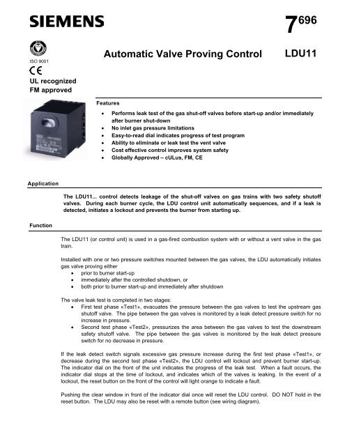
ISO 9001Automatic Valve Proving Control7 696LDU11UL recognizedFM approvedFeatures• Performs leak test of the gas shut-off valves before start-up and/or immediatelyafter burner shut-down• No inlet gas pressure limitations• Easy-to-read dial indicates progress of test program• Ability to eliminate or leak test the vent valve• Cost effective control improves system safety• Globally Approved – cULus, FM, CEApplicationThe LDU11... control detects leakage of the shut-off valves on gas trains with two safety shutoffvalves. During each burner cycle, the LDU control unit automatically sequences, and if a leak isdetected, initiates a lockout and prevents the burner from starting up.FunctionThe LDU11 (or control unit) is used in a gas-fired combustion system with or without a vent valve in the gastrain.Installed with one or two pressure switches mounted between the gas valves, the LDU automatically initiatesgas valve proving either• prior to burner start-up• immediately after the controlled shutdown, or• both prior to burner start-up and immediately after shutdownThe valve leak test is completed in two stages:• First test phase «Test1», evacuates the pressure between the gas valves to test the upstream gasshutoff valve. The pipe between the gas valves is monitored by a leak detect pressure switch for noincrease in pressure.• Second test phase «Test2», pressurizes the area between the gas valves to test the downstreamsafety shutoff valve. The pipe between the gas valves is monitored by the leak detect pressureswitch for no decrease in pressure.If the leak detect switch signals excessive gas pressure increase during the first test phase «Test1», ordecrease during the second test phase «Test2», the LDU control will lockout and prevent burner start-up.The indicator dial on the front of the unit indicates the progress of the leak test. When a fault occurs, theindicator dial stops at the time of lockout, and indicates which of the valves is leaking. In the event of alockout, the reset button on the front of the control will light orange to indicate a fault.Pushing the clear window in front of the indicator dial once will reset the LDU control. DO NOT hold in thereset button. The LDU may also be reset with a remote button (see wiring diagram).
- Page 3: Mechanical designThe LDU control in
- Page 6 and 7: Wiring and setting of LDU… Single
- Page 8 and 9: Trouble ShootingIn the event of a l
- Page 10 and 11: Connection examples for leak test b
- Page 12: Represented By:POWER EQUIPMENT COMP
ISO 9001<strong>Automatic</strong> <strong>Valve</strong> <strong>Proving</strong> <strong>Control</strong>7 696<strong>LDU11</strong>UL recognizedFM approvedFeatures• Performs leak test of the gas shut-off valves before start-up and/or immediatelyafter burner shut-down• No inlet gas pressure limitations• Easy-to-read dial indicates progress of test program• Ability to eliminate or leak test the vent valve• Cost effective control improves system safety• Globally Approved – cULus, FM, CEApplicationThe <strong>LDU11</strong>... control detects leakage of the shut-off valves on gas trains with two safety shutoffvalves. During each burner cycle, the LDU control unit automatically sequences, and if a leak isdetected, initiates a lockout and prevents the burner from starting up.FunctionThe <strong>LDU11</strong> (or control unit) is used in a gas-fired combustion system with or without a vent valve in the gastrain.Installed with one or two pressure switches mounted between the gas valves, the LDU automatically initiatesgas valve proving either• prior to burner start-up• immediately after the controlled shutdown, or• both prior to burner start-up and immediately after shutdownThe valve leak test is completed in two stages:• First test phase «Test1», evacuates the pressure between the gas valves to test the upstream gasshutoff valve. The pipe between the gas valves is monitored by a leak detect pressure switch for noincrease in pressure.• Second test phase «Test2», pressurizes the area between the gas valves to test the downstreamsafety shutoff valve. The pipe between the gas valves is monitored by the leak detect pressureswitch for no decrease in pressure.If the leak detect switch signals excessive gas pressure increase during the first test phase «Test1», ordecrease during the second test phase «Test2», the LDU control will lockout and prevent burner start-up.The indicator dial on the front of the unit indicates the progress of the leak test. When a fault occurs, theindicator dial stops at the time of lockout, and indicates which of the valves is leaking. In the event of alockout, the reset button on the front of the control will light orange to indicate a fault.Pushing the clear window in front of the indicator dial once will reset the LDU control. DO NOT hold in thereset button. The LDU may also be reset with a remote button (see wiring diagram).
Mechanical designThe LDU control includes:- The synchronous motor with its gear train and step action sequence switch- The camshaft with its 15 nonadjustable cams- The program indicator at the head of the camshaft- One main and one auxiliary relay- The lockout relay which can be electrically reset from a remote location- The unit fuse and a spare fuseThe plug-in base carries the following terminals:- 24 connection terminals- 3 earth terminals- 3 neutral terminals, prewired to terminal 2 (neutral input)The front dial provides information about the program sequence, the type of fault and the point in time thefault occurred, using easy-to-remember symbols.Technical dataGeneral unit dataEnvironmentalconditionsMains voltage- <strong>LDU11</strong>.523A17- <strong>LDU11</strong>.523A27AC 100 V –15 %...AC 110 V +10 %AC 220 V –15 %...AC 240 V +10 %Mains frequency 50...60 Hz ±6 %Power consumption- During the test3.5 VA- During operation2.5 VAPrimary fuse (external)T10 / 500VUnit fuse T6.3H250V to IEC 127Perm. input current at terminal 15 APerm. Current rating of control terminals 4 ARequired switching capacityof pressure switchmin. 1 A, AC 250 VMountingIn a panel or control cabinetMounting orientationNo restrictionsDegree of protection NEMA 1, 2, 5, 12, 13Weight- <strong>LDU11</strong>...4 lbs- Plug-in base½ lbTransportTemperature range -58...+140 °FOperationTemperature range -5...+140 °FApprovals (110 V only):FM J.I. 1Z2A6.AF Dec 1995cULusFile MH26883CSA Certificate 1370842Approvals (110 V and 220 V):CE Electromagnetic compatibility EMC 89 / 336 EEC incl. 92 / 31 EECCE Directive for gas appliances90 / 396 EECPage 3/11
Program and lockout indicatorIn the event of lockout, the LDU control stops and the position indicator on the front of theunit lights bright orange. The symbol that stops above the reading mark indicates the testphase during which lockout occurred and also gives the number of programming steps completedfrom the start of this test phase (1 step = 2.5 seconds). In the event of lockout, allterminals receiving voltage from the control unit will be deenergized, except terminal 13,which is used for lockout indication. The clear window in front of the indicator dial is thereset button. Push once to reset the unit. After a reset, the programming mechanism automaticallyreturns to its start position to immediately program a new valve leak test.NoteDo not press and hold the reset button for more than 10 seconds.Calculating the leakage rate escaping from a length of pipeV Leak = (P I -Pset )P xatmxxt TestLegendSymbol UnitDescriptionVleak ft 3 / hr <strong>Valve</strong> leakage rate in ft 3 per hourPI PSI Inlet gas pressure. Pressure upstream of both shut-off valves.Pset PSI Gas pressure setting on pressure switch I (normally set to 50 % of PI)Patm PSI Atmospheric Pressure downstream of gas valves. Typically 14.7 PSI.V ft 3 / hr Volume between the gas valves to be tested. See table (1).Ttest seconds Fixed at 22.5 seconds for test 1, and 27.5 seconds for test 2.Pipe SizeTotal Gas Volume (cu ft)" NPT by Pipe Length between valvesSiemensVGD<strong>Valve</strong>s.5 ft. 1 ft. 1.5 ft. 2 ft. 3.25 ft. 5 ft.0.50 0.006 0.008 0.01 0.0130.75 0.01 0.0125 0.015 0.021.00 0.01 0.013 0.016 0.019 0.025 0.0341.50 0.026 0.022 0.032 0.042 0.052 0.064 0.0882.00 0.028 0.043 0.055 0.067 0.078 0.102 0.1382.50 0.046 0.08 0.103 0.13 0.15 0.177 0.2473.00 0.054 0.17 0.191 0.222 0.242 0.311 0.44.00 0.106 0.21 0.3 0.37 0.466 0.508 0.65Table 1. Volume between gas valves.Example leak detection calculations can be found in the following section under single and dualswitches.Page 5/11
Wiring and setting of LDU… Single Leak Detection Pressure Switch:<strong>LDU11</strong>1415NCCNOPressure Switch I1617During Test 1, power is on Terminal 15. After the area between the gas valves has beenevacuated of pressure, the switch should have power through terminal 15 to terminal 16. If themain gas valve is leaking, the area between the gas valves fills with gas, leak detection pressureswitch I trips, sending power to terminal 17, causing a lockout.During Test 2, Terminal 15 is powered, and with pressure between the gas valves, terminal 17will also be powered. If the blocking gas valve is leaking, the area between the gas valves lossespressure. Leak detection pressure switch I trips, power is sent to terminal 16, resulting in alockout.Leak detection pressure switch should be set at 50% of the gas pressure upstream of themain shut-off valve.Example Leakage Rate CalculationUsing Siemens 1-1/2” VGD gas valves with an inlet gas pressure of .5 PSI,calculate the expected leakage rate which will cause the <strong>LDU11</strong> to lockout setting one leak detectionpressure switch at .25 PSI:V Leak = (P I -Pset )P xatmxxt TestPI= .5 PSIPset = .25 PSIV Leak =(.5 - .25) * .026 * 360014.7 * 22.5 (test1)= 0.07 ft 3 /hrPatmV= 14.7 PSI= .026 ft 3 (From table 1)V Leak =(.5 - .25) * .026 * 360014.7 * 27.5 (test2)= 0.06 ft 3 /hrTtest = 22.5 s (test 1)= 27.5 s (test 2)In this example, if the 1 st gas valve is leaking at a rate of 0.07 ft 3 /hr orgreater, the LDU will lockout during test 1. If the 2 nd gas valve is leakingat a rate of 0.06 ft 3 /hr or greater, the LDU will lockout during test 2.NoteIf the maximum permissible gas leakage rate (Vleak) exceeds the desired leakage testingrate, use dual leak detection pressure switches.Page 6/11
Wiring and setting of LDU… Dual Leak Detection Pressure Switches:<strong>LDU11</strong>1415NCCNOPressure Switch GNCCNOPressure Switch A1617During Test 1, Terminal 15 is powered. After the area between the gas valves has beenevaluated of pressure, pressure G switch should have power through terminal 15 to terminal 16.If the main gas valve is leaking, the area between the gas valves fills with gas, pressure switch Atrips, sending power to terminal 17, causing a lockout.Switch A needs to be set up to a maximum of 50% of the available gas pressure through thevalves. The lower the pressure switch is set, the smaller of a leak will be detected through theblocking (downstream) gas valve. Setting the switch at or near atmospheric pressure may causenuisance lockouts.During Test 2, Terminal 15 is powered. With pressure between the gas valves, terminal 17 willalso have power through pressure switch A. If the blocking gas valve is leaking, the areabetween the gas valves losses pressure, and pressure switch G trips, power is sent to terminal16, causing a lockout.Pressure Switch G need to be set at a minimum of 50%, up to 90%, of the inlet gas pressurethrough the valves. The higher this switch is set, the smaller a leak will be detected through themain (upstream) gas valve. Setting the pressure switch G at or near the inlet pressure maycause nuisance lockouts due to regulator fluctuations.ExampleUsing Siemens 1-1/2” VGD gas valves with an inlet gas pressure of .5 PSI, calculate the expectedleakage rate which will cause the <strong>LDU11</strong> to lockout with two LDU pressure switches, Paset at .1 PSI, and Pg set at .4 PSI:(Pressure differential* V * 3600V Leak = P atmx t TestPIPa= .5 PSI= .1 PSIV Leak =(.1) * .026 * 360014.7 * 22.5 (test1)= 0.027 ft 3 /hrPgPatm= .4 PSI= 14.7 PSIV Leak =(.5 - .4) * .026 * 360014.7 * 27.5 (test2)= 0.022 ft 3 /hrV= .026 ft 3 (From table 1)T test = 22.5 s (test 1)= 27.5 s (test 2)In this example, if the 1 st gas valve is leaking at a rate of 0.027 ft 3 /hr or greater,the LDU will lockout during test 1. If the 2 nd gas valve is leaking at a rate of0.022 ft 3 /hr or greater, the LDU will lockout during test 2.Page 7/11
Trouble ShootingIn the event of a lockout, the following steps need to be performed to determine the cause.1) Check the leak detection switch to ensure it is an automatic reset switch.2) Determine at which point in the leak test sequence the lockout occurred, by viewing thefront dial of the LDU control.3) If the lockout occurs during Test 1, manually leak test the upstream gas valve as recommendedby NFPA 86. If the main valve is leaking, lockout the appliance and replace thevalve.4) If the lockout occurs during Test 2, proceed to step 5.5) Determine the set-point of the leak test pressure switch. Check the inlet pressure in thegas train and the set point of the leak detection switch. Use the guidelines on the previouspages. Re-adjusting the leak detect pressure switch and reset the LDU.6) Check the wiring and functionality of the leak test pressure switch. If faulty, replaceand/or rewire.7) Manually leak test the downstream valve as recommended by NFPA 86. If found to beleaking, lockout the appliance and replace the valve.8) Reset the LDU by pushing the clear window in front of the indicator dial (do not hold in).9) Contact local Siemens combustion representative for assistance.Page 8/11
Connection examples for leak test before burner start-up:The LDU control may be wired in many different manners, depending upon application, burnercontrol version and sequence of operations. Below is the generic wiring diagram for performing thetest before burner start-up. Contact Siemens with questions or for assistance.<strong>LDU11</strong>...Line VoltageBurnerOperating<strong>Control</strong>(ON/OFF)OptionalRemoteResetButton181329Downstream(Blocking) SOVN411Upstream(Main) SOV513External Alarm(Optional)7Vent <strong>Valve</strong>(Optional)Flame SafeguardTerminalsTerminal whichPowers MainGas <strong>Valve</strong>s1012141516NCCTerminal whichPowers FlameSafeguard617NO<strong>Automatic</strong> ResetPressure Switch(See Options)Page 9/11
Connection examples for leak test before burner start-up and after shut down with LFL burner control:Below is the wiring diagram using a LFL flame safeguard performing the leak test before burnerstart-up and after a controlled shut-down. This diagram only depicts the wires that are connectedto the LDU control. Please consult Siemens manual 7451 for further wiring instructionsfor the LFL burner control.<strong>LDU11</strong>...LFL FlameSafeguardTerminalsOptional RemoteReset Button182N419Downstream(Blocking) SOV9311Upstream(Main) SOV10413External Alarm(Optional)8514111976Proof-of-ClosureSwitch(es)202123248151617NCNOC<strong>Automatic</strong> ResetPressure Switch(See Options)Burner Operating<strong>Control</strong> (On/Off)612102219The base plates of the LDU and LFL controls are the same dimensions. Each is keyed during production inorder that the controls may not be installed into the incorrect base plate.Page 10/11
Dimensions in inchesDimensions<strong>LDU11</strong>... with plug-inbase AGM11518,91 17/165/81 1/16 1 1/161 3/81/444213 14 15 16 17 18 19 20 21 22 23 241218,9111098765314,42432N321AGM11©April 2003 Siemens Building TechnologiesDraft - Subject to changePage 11/11
Represented By:POWER EQUIPMENT COMPANY2011 Williamsburg RoadRichmond, VA 23231Ph. 804-236-3800Fx. 804-236-3882www.peconet.com


