HYDRAULIC FLUID CONVERSION FROM MIL-PRF - BellCustomer ...
HYDRAULIC FLUID CONVERSION FROM MIL-PRF - BellCustomer ...
HYDRAULIC FLUID CONVERSION FROM MIL-PRF - BellCustomer ...

You also want an ePaper? Increase the reach of your titles
YUMPU automatically turns print PDFs into web optimized ePapers that Google loves.
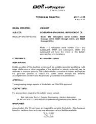
TECHNICAL BULLETIN412CF-12-1023 January 2013MODEL AFFECTED:SUBJECT:412CF<strong>HYDRAULIC</strong> <strong>FLUID</strong> <strong>CONVERSION</strong> <strong>FROM</strong> <strong>MIL</strong>-<strong>PRF</strong>-5606 TO <strong>MIL</strong>-<strong>PRF</strong>-87257HELICOPTERS AFFECTED: Serial numbers 46400 through 46499.[Serial number 46500 and subsequent will have theintent of this bulletin accomplished prior to delivery.]COMPLIANCE:At customer’s option.DESCRIPTION:Bell Helicopter has determined that <strong>MIL</strong>-<strong>PRF</strong>-87257 (C-072) hydraulic fluid isacceptable for use as an alternate for the current <strong>MIL</strong>-<strong>PRF</strong>-5606 (C-002) hydraulic fluidused in the Model 412CF helicopters. Part I of this bulletin provides a procedure toretrofit helicopter with the appropriate decals. Part II of this bulletin providesrecommended procedures for introducing the new hydraulic fluid into the systems.APPROVAL:The engineering design aspects of this bulletin are FAA/ODA approved.CONTACT INFO:For any questions regarding this bulletin, please contact:Bell Helicopter Product Support Engineering - Medium HelicoptersTel: 450-437-6201 / 1-800-363-8028 / psemedium@bh.comTB 412CF-12-102Page 1 of 9ECCN EAR99
MANPOWER:Approximately 1.0 man-hour is required to accomplish Part 1 of this bulletin.Accomplishment of Part 2 of this bulletin using attrition method during normalmaintenance will not require additional man-hours. The mixing of fluids per the attachedprocedure will require a total of approximately 9.0 man-hours.WARRANTY:There is no warranty credit applicable for parts or labor associated with this bulletin.MATERIAL:Required Material:The following material is required for the accomplishment of this bulletin and may beobtained through your Bell Helicopter Textron Supply Center.Part Number Nomenclature Qty205-076-142-105205-076-224-101DecalDecal22Consumable Material:The following material is required to accomplish this bulletin, but may not requireordering, depending on the operator’s consumable material stock levels. This materialmay be obtained through your Bell Helicopter Textron Supply Center.Part Number Nomenclature Qty Reference *<strong>MIL</strong>-<strong>PRF</strong>-872573950 ScotchcalCommercialHydraulic FluidEdge SealerAliphatic NaphthaA/RA/RA/RC-072C-349C-305* C-XXX numbers refer to the consumables list in BHT-ALL-SPM Standard Practices Manual.SPECIAL TOOLS:None required.WEIGHT AND BALANCE:Not affected.ELECTRICAL LOAD DATA:Not affected.TB 412CF-12-102Page 2 of 9ECCN EAR99
REFERENCES:C-12-146-000/MY-001 Illustrated Parts BreakdownBHT-412CF-IPB Illustrated Parts BreakdownC-12-146-000/MF-001 Maintenance ManualPUBLICATIONS AFFECTED:C-12-146-000/MY-001Illustrated Parts BreakdownBHT-412CF-IPB Illustrated Parts BreakdownC-12-146-000/MF-001 Maintenance ManualBHT-412CF-FM-1 Flight ManualC-12-146-000/MB-002 Flight ManualC-12-146-000/MS-002 Standard Practice ManualBHT-ALL-SPM Standard Practice ManualACCOMPLISHMENT INSTRUCTIONS:PART I. Decal Replacement1. Prepare helicopter for maintenance.2. Gain access to both hydraulic reservoirs by removing forward pylon fairing.3. Remove existing decals P/N 205-076-142-103 from hydraulic reservoirs P/N 205-076-135-007/-109. Thoroughly wipe surfaces with a clean cloth dampened withAliphatic Naphtha (C-305) prior to receiving the new decals.4. Install new decals P/N 205-076-142-105 on hydraulic reservoirs P/N 205-076-135-007/-109.5. Remove existing decals P/N 205-076-224-001 from No.1 and No.2 hydraulic groundtest fitting area. Thoroughly wipe surfaces with a clean cloth dampened withAliphatic Naphtha (C-305) prior to receiving the new decals.6. Install new decals P/N 205-076-224-101 on No.1 and No.2 hydraulic ground testfitting area.7. Apply clear edge sealer (C-349) allowing 1/8 inch overlap on all sides of newlyinstalled decals in steps 4 and 6.8. Reinstall forward pylon fairing.9. Make an entry in the helicopter logbook and historical records indicating compliancewith Part I of this Technical Bulletin.TB 412CF-12-102Page 3 of 9ECCN EAR99
PART II. Fluid ConversionMethod 1:Introduction of fluid by attrition.-NOTE-This method will not permit taking advantage of the improvedcharacteristics of hydraulic fluid C-072 until full conversionhas been accomplished.1. This method is accomplished by adding C-072 hydraulic fluid during normalservicing of the aircraft (topping off).2. Make an entry in the helicopter logbook and historical service records indicatingcompliance with Part II Method 1 (intermixed fluids) of this Technical Bulletin.Method 2:Complete fluid replacement of all hydraulic systems to C-072 hydraulicfluid.Phase 11. Hydraulic test stand.a. Provide a hydraulic test stand conforming to requirements stated in C-12-146-000/MF-001 Chapter 29.-NOTE-If hydraulic test stand does not have dual hoses, perform thefollowing procedure on each system in turn.b. Drain fluid from hydraulic test stand until 50% of the total capacity of C-002hydraulic fluid remains. Discard excess hydraulic fluid per applicable shoppractice.c. Replace drained hydraulic test stand fluid with C-072.2. Aircraft Procedures.a. Flight controls.(1) Remove hydraulic test coupling access doors for hydraulic system No.1 andNo.2 below left cargo door opening.(2) Connect hydraulic test stand to hydraulic systems No.1 and No.2 quickdisconnect fittings.TB 412CF-12-102Page 4 of 9ECCN EAR99
(3) Apply electrical power to the aircraft.(4) Using hydraulic test stand apply 1000 psi to aircraft hydraulic pressuresystems No.1 and No.2.(5) Let hydraulic test stand run for 30 minutes.(6) Stroke flight control actuators (collective, both cyclic, tail rotor) by movingthe cyclic control, collective control and operating the pedals through 5complete cycles.(7) Cycle HYDR SYS No.1 and HYDR SYS No.2 switches, located on thepedestal miscellaneous control panel, to the ON and OFF position 5 times inapproximately 2 second intervals.(8) Turn off hydraulic test stand.(9) Turn off electrical power.b. Rotor brake.(1) Remove doors/panels to gain access to rotor brake bleed valve.(2) Slip rubber hose on the end of valve extension and run it to a suitablecontainer or place rags and container under bleed valves to catch fluidduring bleeding.(3) Fully loosen bleed valve on brake assembly.(4) Slowly pull master cylinder lever down and hold. Do not allow lever to passcenter into the park position.(5) Close bleed valve and replenish master cylinder with C-072.(6) Repeat (3) through (5).(7) Repeat (1) through (6) for the other bleed valve.(8) Bleed each bleed valve per C-12-146-000/MF-001 Chapter 63.(9) Reinstall doors and panels.TB 412CF-12-102Page 5 of 9ECCN EAR99
Phase 2 – After 3 flight hours or two weeks following Phase 11. Hydraulic test stand.-NOTE-If hydraulic test stand does not have dual hoses, perform thefollowing procedure on each system in turn.a. Drain hydraulic test stand of hydraulic fluid mix and discard per applicable shoppractice.b. Add 75% of the total cart capacity of hydraulic fluid C-072 and 25% of the totalcart capacity of hydraulic fluid C-002.2. Aircraft Procedures.a. Flight controls.(1) Remove hydraulic test coupling access doors for hydraulic system No.1 andNo.2 below left cargo door opening.(2) Connect hydraulic test stand to hydraulic system No.1 and No.2 quickdisconnect fittings.(3) Apply electrical power to the aircraft.(4) Using hydraulic test stand apply 1000 psi to aircraft hydraulic pressuresystems No.1 and No.2.(5) Let ground cart run for 30 minutes.(6) Stroke flight control actuators (collective, both cyclic, tail rotor) by movingthe cyclic control, collective control and operating the pedals through 5complete cycles.(7) Cycle HYDR SYS No.1 and HYDR SYS No.2 switches, located on thepedestal miscellaneous control panel, to the ON and OFF position 5 times inapproximately 2 second intervals.(8) Turn off hydraulic test stand.(9) Turn off electrical power.b. Rotor brake.TB 412CF-12-102Page 6 of 9ECCN EAR99
(1) Remove doors/panels to provide access to rotor brake bleed valve.(2) Slip rubber hose on the end of valve extension and run to a suitablecontainer or place rags and container under bleed valves to catch fluidduring bleeding.(3) Fully loosen bleed valve on brake assembly.(4) Slowly pull master cylinder lever down and hold. Do not allow lever to passcenter into the park position.(5) Close bleed valve and replenish master cylinder with C-072.(6) Repeat (3) through (5).(7) Repeat (1) through (6) for the other bleed valve.(8) Bleed each bleed valve per C-12-146-000/MF-001 Chapter 63.(9) Reinstall doors and panels.Phase 3 – After 3 flight hours or two weeks following Phase 21. Hydraulic test stand.-NOTE-During Phase 3, the oil from the return line is directed into asuitable container. To avoid wasting fluid, perform all stepsreported below in tight sequence without leaving systempressurized unnecessarily. If stops are required to preparethe next step, turn off hydraulic test stand.a. Drain hydraulic test stand of fluid mix, discard per applicable shop practice.b. Completely fill with C-072 (100% of the total hydraulic test stand capacity).2. Aircraft Procedures.a. Remove forward pylon fairing, giving access to reservoirs.b. Completely drain fluid from No.1 and No. 2 hydraulic reservoirs into a suitablecontainer by disconnecting hose from suction outlet fitting.c. Refill both No.1 and no. 2 hydraulic reservoirs with C-072 to correct level.TB 412CF-12-102Page 7 of 9ECCN EAR99
d. Flight controls.(1) Remove hydraulic test coupling access doors for hydraulic system No.1 andNo.2 below left cargo door opening.(2) Connect hydraulic test stand hoses to both aircraft hydraulic quickdisconnect fittings. Disconnect the return hoses from the hydraulic teststand and direct them into an appropriate container to collect the discardedfluid.(3) Apply electrical power to the aircraft.(4) Turn on hydraulic test stand in order to supply 1000 psi of pressure and 3GPM flow to System 1 only. System 2 must remain unpressurized.(5) Stroke flight control actuators (collective, both cyclic, tail rotor) by movingthe cyclic control, collective control and operating the pedals through 5complete cycles.(6) Cycle HYDR SYS No.1 switch, located on the pedestal miscellaneouscontrol panel, to the ON and OFF position 5 times in approximately 2second intervals.(7) Let the hydraulic test stand run for 1 minute.(8) Turn off hydraulic test stand.(9) Turn on hydraulic test stand in order to supply 1000 psi of pressure and 3GPM flow to System 2 only. System 1 must remain unpressurized.(10) Stroke flight control actuators (collective, both cyclic, tail rotor) by movingthe cyclic control, collective control and operating the pedals through 5complete cycles.(11) Cycle and HYDR SYS No.2 switch, located on the pedestal miscellaneouscontrol panel, to the ON and OFF position 5 times in approximately 2second intervals.(12) Let the hydraulic test stand run for 1 minute.(13) Turn off hydraulic test stand.(14) Hook up both return lines to manifold cart and turn on both hydraulicsystems to 1000 psi and 5 GPM.(15) Leave ground cart running for 5 minutes.TB 412CF-12-102Page 8 of 9ECCN EAR99
(16) Turn off hydraulic test stand.(17) Turn off electrical power.(18) Replenish each reservoir level to proper levels if required.(19) Replace all 4 hydraulic filters.e. Rotor brake.(1) Remove doors/panels to provide access to rotor brake bleed valve.(2) Slip rubber hose on the end of valve extension and run to a suitablecontainer or place rags and container under bleed valves to catch fluidduring bleeding.(3) Fully loosen bleed valve on brake assembly.(4) Slowly pull master cylinder handle down and hold. Do not allow handle topass center into the park position.(5) Close bleed valve and replenish master cylinder with C-072.(6) Repeat (3) through (5).(7) Repeat (1) through (6) for the other bleed valve.(8) Bleed each bleed valve per C-12-146-000/MF-001 Chapter 63.(9) Reinstall fairings, doors and panels, make helicopter ready for flight.3. Make an entry in the helicopter logbook and historical service records indicatingcompliance with Part II Method 2 (complete fluid conversion) of this TechnicalBulletin.TB 412CF-12-102Page 9 of 9ECCN EAR99