Flowserve Gaseous Noise Control Brochure - Flowserve Corporation
Flowserve Gaseous Noise Control Brochure - Flowserve Corporation
Flowserve Gaseous Noise Control Brochure - Flowserve Corporation

Create successful ePaper yourself
Turn your PDF publications into a flip-book with our unique Google optimized e-Paper software.
flowserve.com<strong>Flowserve</strong> <strong>Gaseous</strong> <strong>Noise</strong> <strong>Control</strong>Experience In Motion1
IndexSectionPage1 Introduction to <strong>Noise</strong>........................................... 31.1 Pressure Profiles Through <strong>Control</strong> Valves........ 31.2 <strong>Gaseous</strong> Severe Service.................................... 31.3 Factors Impacting <strong>Noise</strong>................................... 31.4 Prediction Techniques....................................... 71.5 Additional Selection Factors.............................. 72 Product Comparison............................................ 83 Stealth.................................................................. 104 TigerTooth............................................................ 125 MegaStream......................................................... 136 Type III................................................................. 147 Type II.................................................................. 148 Type I................................................................... 159 RLS-System......................................................... 1610 MultiStream......................................................... 1611 Multi-Hole............................................................ 1712 SilentPac.............................................................. 1713 Z-Trim.................................................................. 1814 Downstream Plates.............................................. 192
flowserve.comThe Bernoulliprinciple:When the fluidpressure in thevalve drops, thefluid velocityrises.1. Introduction to <strong>Noise</strong>1.1 Pressure Profiles Through <strong>Control</strong> ValvesAs a fluid travels through a conventional single-seatedglobe-style control valve, a vena contracta (point of narrowestflow restriction) develops directly downstream ofthe narrowest throttling point. At the point of vena contractathe fluid reaches a minimum pressure and maximumvelocity which rapidly recovers to a lower pressure thanthe inlet pressure (see Figure 1.1: Pressure Drop througha <strong>Control</strong> Valve). Due to the Bernoulli principle, when thefluid pressure in the valve drops, the fluid velocity rises(see Figures 1.2: Velocity through a <strong>Control</strong> Valve). Asthe velocity of the fluid increases, the noise generated byturbulence in the fluid also increases. A significant rise invelocity can produce noise beyond safe limits.1.2 <strong>Gaseous</strong> Severe ServiceHigh pressure drops in gas services will generate turbulencein the fluid flow downstream of the pressure drop.As a direct result of the turbulence, noise is radiated tothe surrounding area by the downstream piping system(Figure 1.3: <strong>Noise</strong> Radiating from Downstream Piping).In situations where equipment damage or personal injurycould be caused by a noise source, attenuation is mandatory.Tests have demonstrated that control valve noise increasesproportional to the velocity cubed (SPL ~ V3). Moderatelyhigher velocities can produce significantly loudernoise. Substantial noise can be generated even when velocitiesare significantly less than sonic.Mechanical vibration accompanies high acoustic noiselevels. Acoustic noise and mechanical vibration levels aregreatly compounded (up to 50 times) when the frequencyof the excitation matches acoustic and/or mechanicalnatural frequencies of the system.<strong>Noise</strong> suppression solutions should always be consideredin high pressure drop, high flow rate or resonantnoise applications.<strong>Control</strong> Valve noise is measured in decibels (dBa). Decibelsuse a logarithmic scale, doubling the energy level ofsound pressure wave will cause the noise level to increaseby about 6 dBa. The dBa scale is structured to the humanear, the lowest noise a human can hear is around 0 dBaand a rivet gun is around 100 dBa. Ear protection shouldbe considered when noise levels are above 85 dBa.Uncontrolled noise is a significant problem that can leadto serious health problems, vibration and equipmentdamage. The health problems caused by noise are oftenthought to be limited to hearing damage. However, exposureto excessive noise can cause damage to internalorgans, and in extreme cases, can kill. Vibration damageis the most common equipment damage, leading toworn, failed parts, broken support systems and sensorinstability. In some rare cases, noise levels can spiral outof control even rupturing lines. Often equipment damagecaused by noise is hidden, constantly wearing outparts that require frequent replacement. <strong>Noise</strong> predictionsshould be performed on all controls valves flowinggasses to verify the suitability of the equipment.1.3 Factors Impacting <strong>Noise</strong>Fluid VelocityThe most frequently used solution to high levels of controlvalve noise is to reduce the pressure from the valve inlet tooutlet gradually, eliminating pressure and velocity spikesthroughout the trim (Figure 1.4: Pressure through a Multi-Stage Valve). By lowering the pressure gradually, lowervelocities are created. The lower velocities generate lowernoise levels. Successfully applying this technique requirescontrolling the gas velocity through the valve trim and atall points from the inlet to the outlet of the valve.Occasionally fluid velocities at the valve outlet or even inthe downstream pipe can cause excessive noise. In these3
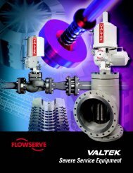
flowserve.comOSFigure 1.3: <strong>Noise</strong> Radiating from Downstream PipingSmall Flow PassagesSmall flow passages accentuate the friction formed bythe passage walls. As the passage grows smaller, morepressure is required to force the fluid to flow. Many valvedesigns use small passages to create frictional losses toreduce the pressure.Mutual ImpingementBy directing two flows to impact each other at 180 degrees,a highly turbulent zone is created. This turbulentzone dissipates energy. With one flow working againstthe opposing flow, the pressure is reduced without addingvelocity to the flow.TurnsEach sudden turn in the fluid flow path will cause thepressure in a fluid to drop. A small velocity increase occursas the fluid makes the turn. The angle of the turn canhave a dramatic effect on the energy loss from the fluidas it makes the turn. Angles sharper than 90 degrees aredifficult to manufacture, but have more of an effect onreducing pressure.Peak Frequency EffectMost noise in a control valve produces a range of frequencieswhich have a bell-curve type distribution anda peak frequency. Changes in the geometry of the valvedesign will shift this peak frequency.Increasing PressureFigure 1.4: Pressure Through a Multi-Stage ValveShifting the peak frequency higher is very desirable fortwo primary reasons. First, it can shift the frequency outof the range of human hearing. This lowers the perceivednoise and reduces the damage to human organs. Second,it reduces the level of noise that can pass through thepipe. The natural frequency of pipe is low. When the frequencyof the noise matches the natural frequency of thepipe, the pipe will resonate in sympathy, easily passingthe noise from the inside to the outside of the pipe. Higherfrequencies don’t have this resonance and will passless noise out of a pipe. Higher peak frequencies will becontained inside the pipe better than lower frequencies.5
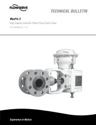
Gallery Flow AreaInlet PassagewayOutlet PassageInternal Trim Flow AreaFigure 1.5: Critical Velocity ZonesA common method to raise the peak frequency is to makesmaller outlet holes in the noise control device. Cutting ahole diameter in half can lower the overall noise level byup to five decibels.WaveCracker TechnologyWaveCracker is a technology that reduces noise as flowpasses through passages with irregularly shaped crosssections. Tests have shown this technology effectivelycan reduce noise by more than ten decibels.WaveCracker works by forming an irregular cross sectionshape (see Figure 1.6: WaveCracker Passages). Soundwaves reflecting off the walls of the passage have irregularpatterns. These irregular patterns cause the soundpressure wave to lose intensity as it moves down thepassage.Mass FlowLower pressure drops across control valves will producesignificant noise if the mass flow rate is high. This happensmost often in large valves when many small noisegeneration sites combine to produce a loud cumulativenoise level. Combating this problem is more difficultsince taking the pressure drop in small stages may notbe effective.Acoustical AttenuationAcoustical attenuation can provide a barrier which blocksnoise. This can be done in many ways, from insulatingthe pipe to increasing the distance to the noise source.Careful engineering of a noise solution includes evaluatingany existing or potential attenuation.Harmonic VibrationHarmonic vibration occurs when the natural frequency ofthe pipe and valve approach a common frequency. Thiscauses a noise with a single frequency and a characteristicsound that is often called screech. Since screech occurswhen the frequency of the valve and pipe match, itis not easily predicted. However, simple changes in thevalve geometry can usually solve the problem.6
flowserve.comWave Cracker PassageFigure 1.6: WaveCracker PassagesReflective Surfaces<strong>Noise</strong> coming from a pipe can be amplified by reflectivesurfaces. <strong>Noise</strong> predictions assume a free field, whichis defined as no reflective surfaces. A single flat surfacenear the control valve, like a concrete floor, can add threedecibels to the noise. Each flat hard surface can add anotherthree decibels. Two hard flat surfaces that are parallelto each other will add substantially more than six decibels.Adding walls, a ceiling and a floor can add thirty to fortydecibels.1.4 Prediction TechniquesA number of prediction techniques exist with varying levelsof accuracy for different applications. Using differentprediction techniques to predict the noise of an applicationwill often result is widely varying results. Unfortunately, nostandard exists which is the most accurate for all possibleconditions. Therefore, when noise is a critical factor a studyof the flow conditions, valve design, and the available noiseprediction methods should be undertaken.Valve Manufacturer StandardsMost manufacturers have proprietary techniques which willproduce acceptable predictions under a certain range ofconditions and with equipment the manufacturer is familiarwith. When used outside of the acceptable range or withother equipment, predicted noise calculations can be significantlydifferent than actual noise produced.IEC 60543-8-2In an effort to provide an accurate standard that can be usedto compare different manufacturers, the IEC committeehas developed the IEC standard 60543-8-2. Although thisprediction method is not perfect for all conditions or valvestyles, this method does create a clear baseline to comparedifferent valve models1.5 Additional Selection FactorsThe following factors should be considered before applyingexpensive noise suppression equipment:• How much noise attenuation is actually required?• What are the low-cost alternatives to noise attenuation?• If noise attenuation devices are necessary, what lowercostequipment can be specified? If the predicted soundpressure level (SPL) exceeds 85 or 90 dBA, noise suppressiondevices should be considered. However, highernoise levels may be acceptable if the noise is not associatedwith equip-ment damage and is located in a remotelocation away from people. Other possible low-cost alternativesto noise suppression equipment are:• Piping insulation• Discharging the valve directly into a vessel (allowingthe noise to be absorbed by the vessel)• Relocating the noise source (such as the downstreampiping) outside an enclosed area• Reversing the flow direction through the valve• Reducing the pressure drop across the valve.7
2. Product ComparisonDesign Globe, Multi-Stage <strong>Noise</strong> <strong>Control</strong> Globe, Multi-Stage <strong>Noise</strong> <strong>Control</strong> Globe, Multi-Stage <strong>Noise</strong> <strong>Control</strong>Type Stealth TigerTooth MegaStreamBase Valve Mark Series Mark Series Mark SeriesSize Range 3˝ to 36˝ 1½˝ to 36˝ 1˝ to 36˝Cv Range to 4000 4 to 4000 5 to 10100Flow Direction Flow under the plug Flow under the plug Flow under the plugPressure Stages 6 to 20 2 to 8 1 to 7Features • Attenuation of up to 40 dBa• WaveCracker• Stealth is the most efficient highpressure drop noise attenuation trimever developed• Stealth uses laser-cut discs to createstacked disc seat retainers. The cutsin the discs form channels for thefluid to pass through.• Attenuation of up to 30 dBa• Can be taken apart for cleaning orrepair• TigerTooth uses stacked discs withgrooves, or teeth, to take multiplestaged pressure drops• Self-cleaning design with large passages• Attenuation of up to 20 dBa• MegaStream uses nested cylindersin place of the seat retainer. Eachdrilled cylinder represents a stage ofpressure reductionDesign Globe, Multi-Stage <strong>Noise</strong> <strong>Control</strong> Globe, Multi-Stage <strong>Noise</strong> <strong>Control</strong> Globe, Multi-Stage <strong>Noise</strong> <strong>Control</strong>Type RLS-System MultiStream Multi-hole plugBase Valve FlowTop, FlowPro FlowTop, FlowPro FlowTop, FlowProSize Range 1˝ to 12˝ ½˝ to 12˝ ½˝ to 12˝Cv Range Engineered up to 820 4.6 to 1040 2.9 to 1040Flow DirectionBidirectional Flow,Liquid flow to close Gas flow to openFlow under the plugBidirectional FlowPressure Stages 2 to 6 1 to 4 1Features • Attenuation of up to 30 dBa dependingon the operating conditions• Efficient, modular design• Every stage is controlled, whichresults in a high efficiency even atpartial load• For gas, steam and liquid service toreduce noise• Attenuation of up to 20 dBa dependingon the operating conditions• Efficient, modular design• Easy upgrade from standard, no trimset changes• For gas, steam and liquid service toreduce noise• Attenuation of up to 15 dBa dependingon the operating conditions• Efficient, modular design• For gas, steam and liquid service toreduce noise8
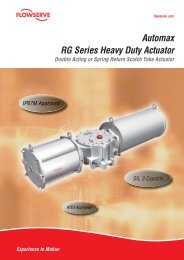
3. StealthIntroductionThe most sophisticated noise attenuation design, Stealth trimeffectively reduces sound pressure levels in the most demandingapplications (Figure 3.1: <strong>Control</strong> Valve with Stealth Trim).The advanced Stealth design combines the most effective noiseand pressure control mechanisms to produce the most efficientnoise reduction trim ever created.DesignStealth is produced by laser cutting circular discs to form fluidpassageways and then braising the discs together to form aseat retainer (Figure 3.2: Stealth Stack). Three different discsare cut and matched together to form a flow path set (Figure3.3: Stealth Discs) (Figure 3.4: Stealth Flow Passage). A numberof disc sets are then stacked together and the whole assembly isbraised together to form a stack.Similar to TigerTooth an important mechanism reducing thepressure in Stealth trim is the sudden expansion and contractionphenomenon that takes place as the flow passes over theteeth. The Stealth trim’s ability to gradually reduce pressurewithout generating high velocities is important for the reductionof noise in the process line.In addition to reducing the pressure gradually, Stealth takes advantageof frequency shifting by providing small outlet holeswhich raise the frequency and lower the noise.An important feature in the noise control capabilities of theStealth is the WaveCracker technology which provides extranoise attenuation without creating extra pressure drops in thevalve.Trim exit flow paths on the Stealth are angled to direct the flowto the valve exit. This feature increases the flow capacity of thevalve and lowers the noise by reducing exit turbulence.Combining the pressure reduction, and velocity control featureswith the noise elimination features of the Stealth produces themost advanced noise elimination technology available.Figure 3.1: <strong>Control</strong> Valve with Stealth Trim10
flowserve.comBase Valve DesignBase valves for the Stealth include the Mark One and Mark 100.Mechanisms at Work• Pressure <strong>Control</strong>• Velocity <strong>Control</strong>• Attenuation• Frequency Shifting• <strong>Noise</strong> Cancellation• WaveCrackerFigure 3.2: Stealth StackFigure 3.3: Stealth DiscsFigure 3.4: Stealth Flow Passage11
4. TigerToothIntroductionDecades of field experience has proven the sophisticated designof the TigerTooth to be one of the most effective noisereduction trims available. Designed to be most effective at highpressure drops, the TigerTooth design effectively reduces thesound pressure levels in the most demanding applications(Figure 4.1: <strong>Control</strong> Valve with TigerTooth Trim).DesignThe TigerTooth design employs highly engineered concentricgrooves (or teeth) machined into the face and backside of aseries of circular stacked discs (called a stack), which form theseat retainer (Figure 4.2: Cross-Sectioned TigerTooth Seat Retainer).Legs separate one disc from another, providing a gapbetween individual discs, forming flow passages.Figure 4.2: Cross-Sectioned TigerTooth Seat RetainerAn important mechanism reducing the pressure inTigerToothtrim is the sudden expansion and contraction phenomenon thattakes place as the flow passes over the teeth. The TigerToothvalve’s ability to gradually reduce pressure without generatinghigh velocities is important for the reduction of noise in theprocess line.In addition to the standard linear and bi-linear designs, Tiger-Tooth can also be designed with a full-open area at the top of thestack to provide additional flow capacity. This design flexibilityallows the TigerTooth to take very high pressure drops whenthrottling low and still deliver high capacities when required,while generating exceptionally low noise levels.Passages in the TigerTooth design are self cleaning. Passagesgrow wider as the fluid passes from the inside to the outside.This allows large solids to easily pass through the trim.Base Valve DesignBase valves for the TigerTooth include the Mark One, Mark Two,Mark Eight, and Mark 100.Figure 4.1: <strong>Control</strong> Valve with TigerTooth TrimMechanisms at Work• Pressure <strong>Control</strong>• Velocity <strong>Control</strong>• Attenuation12
flowserve.com5. MegaStreamIntroductionThe MegaStream design employs a heavy duty drilled-hole seatretainer (cage) with up to seven stages to lower noise levels(Figure 5.1: <strong>Control</strong> Valve with Two Stage MegaStream Trim).With decades of proven experience, the MegaStream controlvalve is the one of the most common solutions to control valvenoise.DesignPressure drops are distributed between the throttling point ofthe plug and seat ring as well as the stages of the retainer. Eachstage is designed to take a small pressure drop, avoiding thehigh velocities present in single-throttling-point trims. Fluid expansionand velocity are controlled by increasing the flow areasof each subsequent stage.Cutting the MegaStream retainer hole size in half will reduce thenoise level by up to 7 dBa through frequency shifting effects.Holes sizes are optimized to balance noise and manufacturability.A standard two stage MegaStream constructed from heavy dutydrilled-hole cylinders. Standard designs eliminate special engineeringwhich results in lower costs and quicker deliveries.Because of parts interchangeability with standard seat retainers,one and two-stage attenuators can be fitted into conventionalMark Series valves without special or additional parts.When more attenuation is needed, seat retainers incorporatingfrom three to seven drilled-hole stages are available. Most ofthe base valve parts are still interchangeable with standard valveconstruction.Special designs are available when process conditions require aspecialized solution. For example, guiding the plug in the cageeliminates the seat ring as a throttling point, which can providemore attenuation at low throttling points.Base Valve DesignBase valves for the MegaStream retainer include the Mark One,Mark Two, Mark Eight, and Mark 100.Mechanisms at Work• Pressure <strong>Control</strong>• Velocity <strong>Control</strong>• Attenuation• Frequency ShiftingFigure 5.1: <strong>Control</strong> Valve with Two Stage MegaStream Trim13
6. Type III 7. Type IIIntroductionUsing the same skirt guided drilled-hole plug as the Type II designand a heavy duty drilled-hole cage, the Type III design iscreated (Figure 6.1: Type III Trim). The Type III system is mosteffective at reducing noise generated by higher pressure drops.The Type III trim offers one or two stages of pressure reductionin a heavy duty design.DesignWhen using two stages of pressure drop, the Type III designhas a skirt guided drilled-hole plug, and a heavy duty drilledholecage. In the single stage style, the heavy duty drilled-holecage is used. Both styles use cage guiding to throttle each stagefor effective noise control over the complete range. Each stagetakes part of the pressure drop to produce the minimum noisewhile still attenuating noise generated upstream. Both designwork by attenuating upstream noise and shifting the noise frequencyhigher.Standardized designs allow for quicker deliveries and lowercosts.Base Valve DesignAvailable in a number of Kammer platforms, the most commonlyused is the 35000 series control valve.Mechanisms at Work• Pressure <strong>Control</strong>• Velocity <strong>Control</strong>• Attenuation• Frequency ShiftingFigure 6.1: Type III TrimIntroductionBy adding a skirt guided drilled-hole plug to the attenuators usedin the Type I design, the Type II design is created (Figure 7.1: TypeII Trim). The Type II system is most effective at reducing noisegenerated by moderate to high pressure drops. The Type II trimoffers up to four stages of pressure reduction.DesignWhen using all four stages of pressure drop, the Type II designhas a skirt guided drilled-hole plug, an inner perforated metalstage, a metal mesh silencer and an outer perforated metalstage. Each stage takes part of the pressure drop to produce theminimum noise while still attenuating noise generated upstream.When only a single stage is required, the skirt guided drilled-holeplug is used. The three stage design uses a skirt guided drilledholeplug along with both the inner and outer stages of the cage.Adding the baffle creates the four stage style. All three designswork by attenuating upstream noise and shifting the noise frequencyhigher.Standardized designs allow for quicker deliveries and lowercosts.Base Valve DesignAvailable in a number of Kammer platforms, the most commonlyused is the 35000 series control valve.Mechanisms at Work• Pressure <strong>Control</strong>• Velocity <strong>Control</strong>• Attenuation• Frequency ShiftingFigure 7.1: Type II Trim14
flowserve.comAs a fluid travels through aconventional single-seatedglobe-style control valve, avena contracta (point of narrowestflow restriction) developsdirectly downstreamof the narrowest throttlingpoint.8. Type IFigure 8.1: Type I TrimThe Type I low noise baffles reduce noise generated by moderatepressure drops (Figure 8.1: Type I Trim). By only changing a fewof parts, the noise reducing cage can be added to the standardvalve without special plugs or seat rings. <strong>Control</strong> of the processis through the standard contoured plug, yielding high turndownand great control. Available with one stage, two stages or twostages with baffles, the Type I trim offers up to three stages ofpressure reduction.When using all three stages of pressure drop, the Type I designhas an inner perforated metal stage, a metal mesh silencerand an outer perforated metal stage. Each stage takes part ofthe pressure drop to produce the minimum noise while still attenuatingnoise generated upstream. When only a single stageis required, the outer perforated metal stage is used. The twostage design uses both the outer and inner stages to create twopressure drops. Adding the baffle creates the three stage style.As the number of stages increase, the noise attenuation also in-creases. All three designs work by attenuating upstream noisewhile shifting the noise frequency higher.Standardized designs allow for quicker deliveries and lowercosts.Available in a number of Kammer platforms, the most commonis the 35000 series control valve.• Pressure <strong>Control</strong>• Frequency Shifting• Velocity <strong>Control</strong>• Attenuation15
9. RLS-System10. MultiStreamIntroductionAvailable with two or three individually throttled stages, (Figure9.1: RLS-System Trim) the RLS-System eliminates noise inmoderate to high pressure drops.DesignBy individually throttling each stage, fluid expansion and velocityis tightly controlled for maximum efficiency at all plug positions.Available with two or three stages, the RLS-System is simple,robust and effective. Using a four flange body, the three stageRLS-System provides for more pressure drop than the two stagesystem. Using small holes in each stage for frequency shifting,the RLS-System produces lower noise levels while attenuatingupstream noise. Standardized designs allow for quicker deliveriesand lower costs.Base Valve DesignAvailable in the FlowTop, FlowPro.Mechanisms at Work• Velocity <strong>Control</strong>• Attenuation• Frequency ShiftingFigure 9.1: RLS-System TrimIntroductionAvailable with five stages, (Figure 10.1: MultiStream Trim) theMultiStream eliminates noise in moderate to high pressuredrops.DesignUsing four drilled hole stages (three downstream of the plug andone upstream) and a contoured plug, the MultiStream providesexceptional nose reduction and excellent turndown. Using smallholes in each stage for frequency shifting, the MultiStream produceslower noise levels while attenuating upstream noise.Base Valve DesignAvailable in the FlowTop and FlowPro.Mechanisms at Work• Pressure <strong>Control</strong>• Velocity <strong>Control</strong>• Attenuation• Frequency ShiftingFigure 10.1: MultiStream Trim16
flowserve.com11. Multi-Hole 12. SilentPacIntroductionUsing a cost effective skirt guided plug head with drilled holes(Figure 11.1: Multi-Hole Trim) the Multi-Hole reduces noisegenerated by moderate pressure drops. Using special plugs andseat rings, all other valve parts remain the same.DesignThe Multi-Hole generates less noise than conventional designsby using small drilled holes in the plug skirt to shift the frequencyand lower noise. Small holes provide effective attenuation ofnoise generated upstream of the plug skirt, lowering the noisetransmitted downstream.Standardized designs allow for quicker deliveries and lowercosts.Base Valve DesignAvailable in the FlowTop and FlowPro.Mechanisms at Work• Pressure <strong>Control</strong>• Velocity <strong>Control</strong>• Attenuation• Frequency ShiftingFigure 11.1: Multi-Hole TrimIntroductionThe SilentPac low noise baffles (Figure 12.1: SilentPac Trim)reduce noise generated by moderate pressure drops. By onlychanging a couple of parts, the noise reducing cage can beadded to the standard valve without special plugs or seat rings.<strong>Control</strong> of the process is through the standard contoured plug,yielding high turndown and great control.DesignStainless steel wire mesh attenuator. The stainless steel attenuatoris welded together to form a single robust part. The processfluid diffuses through the cage silencing noise generatedupstream with very little noise generation.Standardized designs allow for quicker deliveries and lowercosts.Base Valve DesignAvailable in the FlowTop and FlowPro.Mechanisms at Work• Pressure <strong>Control</strong>• Velocity <strong>Control</strong>• Attenuation• Frequency ShiftingFigure 12.1: SilentPac Trim17
13. Z-TrimFigure 13.1: Setball <strong>Control</strong> Valve with Z-TrimIntroductionZ-Trim combines the benefits of an advanced control valve withthe simplicity of a ball valve. Most effective with low to mediumpressure drops, the Z-trim excels at eliminating noise in highflow services. Using the standard Setball (Figure 13.1: Setball<strong>Control</strong> Valve with Z-Trim) or Duball (Figure 13.2: Duball <strong>Control</strong>Valve Z-Trim) as a platform, adding the Z-Trim requires only onepart to be changed.<strong>Noise</strong> <strong>Control</strong> DesignThe simple design of the Z-Trim gets it’s effective noise reductionby passing the fluid through as many as five stages of pressurereduction. Increasing passage areas of each subsequent stageof the Z-Trim allows the gas to expand while maintaining lowvelocities for lower noise.and the valve develops full capacity. This feature gives effectivenoise attenuation at the low end, where pressure drops are high,and still delivers the high capacity expected from a ball valve.Base Valve DesignThe Z-Trim is available in the Duball, Setball and ShearStreamSB control valves.Mechanisms at Work• Pressure <strong>Control</strong>• Velocity <strong>Control</strong>• Attenuation• Frequency ShiftingEach stage provides both attenuation of upstream noise and limitsthe velocity through the trim minimizing noise generation.As the valve opens, fewer stages are taken until the ball is open18
flowserve.com14. Downstream PlatesFigure 14.1: <strong>Control</strong> Valve with Downstream PlatesIntroductionInstalling anti-noise plates downstream of a control valve is asimple, cost effective way to reduce control valve noise, withoutmaking any changes to the valve (see Figure 14.1: <strong>Control</strong>Valve with Downstream Plates). Plates provide lower noise bylowering turbulence, providing back pressure to the valve andproviding attenuation on noise generated inside the valve. Toprovide successful noise attenuation downstream plates needto be fit for the individual application. Plates are most effectivein low to medium pressure drop applications.<strong>Noise</strong> <strong>Control</strong> DesignEach plate incorporates one or more stages. <strong>Noise</strong> controlplates are similar to orifice plates, but have many small passagesinstead of one large hole. Some may have metal mesh orother devices to attenuate noise. Several plate designs are offeredby <strong>Flowserve</strong>, all incorporating the same basic operatingprinciples. To control downstream line turbulence, each stageabsorbs a portion of the pressure drop. As each stage absorbspressure, it also attenuates noise and turbulence developed upstreamof the plate.Base Valve Design<strong>Noise</strong> control plates are used with all styles of <strong>Flowserve</strong> controlvalves.Mechanisms at Work• Pressure <strong>Control</strong>• Velocity <strong>Control</strong>• Attenuation• Frequency Shifting19
<strong>Flowserve</strong> Worldwide<strong>Flowserve</strong> Flow <strong>Control</strong> Division1350 N. Mt. Springs ParkwaySpringville, UT 84663USAPhone: 801 489 8611Fax: 801 489 3719<strong>Flowserve</strong> Essen GmbHManderscheidtstr. 1945141 EssenGermanyPhone: +49 (0)201 8919 5Fax: +49 (0)201 8919 662<strong>Flowserve</strong> (Austria) GmbH<strong>Control</strong> Valves-Villach OperationKasernengasse 69500 VillachÖsterreichPhone: 43 (0) 4242 41 181 0Fax: 43 (0) 4242 41181 50<strong>Flowserve</strong> Australia Pty Ltd.14 Dalmore DriveScoresby Victoria 3179AustraliaPhone: 61 (3) 9759 3300Fax: 61 (3) 9759 3301<strong>Flowserve</strong> India <strong>Control</strong>s Pvt Ltd.Plot # 4, 1A, Road #8 EPIP WhitefieldBangalore, Karnataka, 560066IndiaPhone: 91 80 40146200Fax: 91 80 28410286<strong>Flowserve</strong> Fluid Motion and<strong>Control</strong> (Suzhou)Co., Ltd.No.35, Baiyu Road,Suzhou Industrial Park, SuzhouJiangsu Province, P.R. 215021ChinaPhone: 86 512 6288 8790Fax: 86 512 6288 8736<strong>Flowserve</strong> Pte Ltd12 Tuas Avenue 20Singapore 638824SingaporePhone: 65 6879 8900Fax: 65 6862 4940<strong>Flowserve</strong> de VenezuelaZona Industrial Av. 68No. 149B-155 Zona Industrial IIMaracaibo, Zulia 1042VenezuelaPhone: 582 61 736.1771Fax: 582 61 736.1912<strong>Flowserve</strong> <strong>Corporation</strong>PO Box 209Al Khobar 31952Saudi ArabiaPhone: 9663 857 3146Fax: 9665 4915276<strong>Flowserve</strong>Unit 1, 12 Director RoadSpartan Exit 2Kempton ParkGauteng 1613South AfricaPhone: 27 (0) 11 923 7300Fax: 27 (0) 11 974 6420To find your local <strong>Flowserve</strong> representative,visit www.flowserve.com or call USA 1 800 225 6989FCD FCENBR0067-02 – 01/11<strong>Flowserve</strong> Regional<strong>Flowserve</strong> Canada Corp.9044 - 18th StreetEdmonton, Alberta T6P 1K6CanadaPhone: 780-449-4850Fax: 780-449-4851<strong>Flowserve</strong> Flow <strong>Control</strong>Quick Response Center104 Chelsea ParkwayBoothwyn, PennsylvaniaUSAPhone: 610 497 8600Fax: 610 497 6680<strong>Flowserve</strong> Flow <strong>Control</strong>Quick Response Center5114 Railroad StreetDeer Park, Texas 77536USAPhone: 281 479 9500Fax: 281 479 8511<strong>Flowserve</strong> Flow <strong>Control</strong>Quick Response Center2920 W. Cardinal DriveBeaumont, Texas 77705USAPhone: 409 842 6600Fax: 409 840 5213<strong>Flowserve</strong> <strong>Corporation</strong> has established industry leadership in the design and manufacture of its products. When properly selected, this <strong>Flowserve</strong> product is designed to perform its intended function safely during its useful life.However, the purchaser or user of <strong>Flowserve</strong> products should be aware that <strong>Flowserve</strong> products might be used in numerous applications under a wide variety of industrial service conditions. Although <strong>Flowserve</strong> can (and oftendoes) provide general guidelines, it cannot provide specific data and warnings for all possible applications. The purchaser/user must therefore assume the ultimate responsibility for the proper sizing and selection, installation,operation, and maintenance of <strong>Flowserve</strong> products. The purchaser/user should read and understand the Installation Operation Maintenance (IOM) instructions included with the product, and train its employees and contractors in the safe use of <strong>Flowserve</strong> productsin connection with the specific application.While the information and specifications contained in this literature are believed to be accurate, they are supplied for informative purposes only and should not be considered certified or as a guarantee of satisfactory results by reliance thereon. Nothing containedherein is to be construed as a warranty or guarantee, express or implied, regarding any matter with respect to this product. Because <strong>Flowserve</strong> is continually improving and upgrading its product design, the specifications, dimensions and information containedherein are subject to change without notice. Should any question arise concerning these provisions, the purchaser/user should contact <strong>Flowserve</strong> <strong>Corporation</strong> at any one of its worldwide operations or offices.© 2007 <strong>Flowserve</strong> <strong>Corporation</strong>, Irving, Texas, USA. <strong>Flowserve</strong> is a registered trademark of <strong>Flowserve</strong> <strong>Corporation</strong>.flowserve.com20