You also want an ePaper? Increase the reach of your titles
YUMPU automatically turns print PDFs into web optimized ePapers that Google loves.
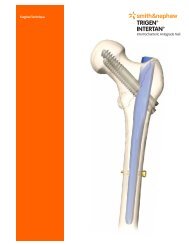
TRIGEN META-NAIL Tibial Nail SystemSurgical TechniqueTable of ContentsIndications............................................................2Implant Specifications ........................................3Surgical TechniquePatient Positioning ....................................................4Incision and Entry Point ............................................6Entry Portal Acquisition ............................................7Entry Portal................................................................8Alternative Technique: Entry Portal ..........................8Fracture Reduction ....................................................10Reducer Removal ......................................................10Implant Measurement ..............................................11Unreamed Technique................................................12Reamed Technique ..................................................13Nail Assembly ..........................................................15Nail Insertion ............................................................16Check Nail Depth......................................................17Locking Screw Measurement ..................................19Locking Screw Insertion............................................19Proximal Locking: Static ............................................20Proximal Locking: Dynamic ......................................20Proximal Locking: Compression ..............................21Distal Locking............................................................21Blocking Screw Insertion TechniqueIncision & Entry Point................................................23Entry Portal Acquisition ............................................23AP Blocking Screw Insertion ....................................24ML Blocking Screw Insertion ....................................25Blocking Screw Insertion With Reducer....................26Stability Blocking Screw Insertion ............................27Nail Cap Insertion ....................................................28Nail ExtractionStandard Technique..................................................30Percutaneous Technique ..........................................30Guide Rod Jamming Technique................................31Catalog Information ............................................32Nota BeneThe technique description herein is made available to the healthcare professional to illustrate theauthors' suggested treatment for the uncomplicated procedure. In the final analysis, the preferredtreatment is that which addresses the needs of the patient.1
IndicationsThe TRIGEN META-NAIL Tibial Nail is indicatedfor fractures of the proximal and distal third ofthe tibia, including the shaft, stable and unstablefractures, non-unions, mal-unions, and for theprophylactic nailing of impending pathologicalfractures.2
TRIGEN META-NAIL Tibial Nail Specifications10ºSpecificationsTRIGEN META-NAIL Tibia(8.5mm)TRIGEN META-NAIL TibiaMaterial TI6AL4V TI6AL4V27mmDiameter 8.5mm 10, 11.5 & 13mmLengths 16-50cm* 16-50cm*Nail Color Grey goldCross Section Round RoundDriving End of Nail (All Kneeand Distal Tibial)Proximal Diameter(driving end)Distal Diameter(non-driving end)12mm8.5mm12mm (10, 11.5 dia.)13mm (13 dia.)10, 11.5 & 13mmSmallest Thru Diameter 4.8mm 5.0mmWall Thickness1.9mm2.3mm (10)3.0mm (11.5)2.3mm (13)Guide Bolt Thread 5/16-24 UNF 5/16-24 UNFScrew Diameter 4.5mm 5.0mmScrew Color Grey goldMajor Diameter 4.5mm 5.0mmMinor Diameter (core) 4.0mm 4.3mmScrew Lengths 25-65mm 25-110mmHex Size 4.7mm 4.7mmTop View of NailAlternative Hex DriversRT Femoral & Recon7.0mm Cannulated ScrewPERI-LOC Locking ScrewAlternative Modes No NoProximal Locking(Driving End)Static LockLocations/OrientationsStatic Locking HoleDimensions17mm/45° Screw Locked w/META-NAIL Cap23mm/45° Threaded w/bushing30mm/25° Threaded40mm/25° ThreadedThreaded 4.3mm minor dia.Threaded 4.7mm major dia.RT Femoral & Recon7.0mm Cannulated ScrewPERI-LOC 4.7mm Hex Driver,PROFIX 4.7mm Hex DriverThreaded 4.5mm minor dia.Threaded 5.3mm major dia.60mmCompression/DynamicSlot LocationCompression/DynamicSlot Diameter/Length10mm4.7mm/7mm10mm5.3mm/7mm2ºML ViewNon-driving End of Nail(AP view)NOTE: These views are not to scale and should be used as apictorial representation only.Degree of Proximal Bend(Herzog)10° 10°Proximal Bend Location 27mm 27mmDistal Locking(Non-Driving End)Static Lock Locations/OrientationsStatic Locking HoleDimensions25mm/ML15mm/AP5mm/ML (Threaded)4.7mm**25mm/ML15mm/AP5mm/ML (Threaded)5.3mm**Degree of Distal Bend 2° 2°Distal Bend Location 60mm 60mm*Set does not include all sizes; Outlier sizes may be special order only.**Most distal hole threaded.3
Surgical TechniquePatient PositioningPosition the patient supine on a radiolucenttable with the unaffected limb extended awayfrom the affected limb. Alternatively, a fracturetable may be used with a pin inserted throughthe calcaneus to place the leg in traction.Flex the affected limb 80-90° and check forlength and rotation by comparison to theunaffected limb.Use a bolster or radiolucent triangle to maintainlimb position. Rotate the C-Arm to ensureoptimal AP and lateral visualization of the entiretibia. A distraction device may also be applied toobtain and/or maintain traction.4
Instruments for Opening the Proximal Tibia3.2mm Tip Threaded Guide WireCat. No. 7163-1690Mini ConnectorCat. No. 7163-118612.5mm Entry ReamerCat. No. 7163-1116HoneycombCat. No. 7167-4075T-HandleCat. No. 7167-4076Entry Portal TubeCat. No. 7167-40603.2mm T-Handle TrocarCat. No. 7167-4074Entry Portal HandleCat. No. 7167-4092Cannulated AwlCat. No. 7167-40005
Surgical Technique (continued)Incision and Entry PointAssemble the Honeycomb (7167-4075), EntryHandle (7167-4092) and Entry Tube (7167-4060).The pieces will lock in place securely at either0° or 180°.A 2cm incision is made in-line with theintramedullary canal. This may be patellarsplitting, medial or lateral parapatellar in itsorientation.The entry point is located just medial to thelateral tibial eminence in the AP view, andin-line with the anterior cortex andintramedullary canal in the lateral.6
Entry Portal AcquisitionAttach a 3.2mm Tip Threaded Guide Wire(7163-1690) to the drill via the Mini Connector(7163-1186) and insert into the proximal tibia to adepth of 4-6cm. The Entry Portal instrumentationserves as a soft tissue protector.In the instance of suboptimal Guide Wireinsertion, rotate the Honeycomb within theEntry Tube to the desired location and insertanother 3.2mm Tip Threaded Guide Wire.Avoid over-insertion of the Guide Wire as this canestablish a false trajectory and lead to fracturemalalignment.7
Surgical Technique (continued)Entry PortalAfter definitive Guide Wire placement, removethe Honeycomb from the Entry Tube along withany additionally inserted Guide Wires andattach the 12.5mm Entry Reamer (7163-1116) topower. Advance over the Guide Wire throughthe Entry Tube to a depth of 4-6cm. Maintainalignment so as to avoid penetration of theposterior cortex.Check position via radiographic imaging andthen remove the 12.5mm Entry Reamer and3.2mm Tip Threaded Guide Wire.Alternative Technique:Entry PortalAttach the T-Handle (7167-4076) to theCannulated Awl (7167-4000) and insert intothe proximal tibia to a depth of 4-6cm. Introducethe 3.2mm T-Handle Trocar (7167-4074) into theback of the assembly prior to insertion in orderto prevent awl slippage and accumulation ofcortical bone within the cannulation.Cannulated Awlwith T-Handle3.2mm T-HandleTrocar8
Instruments for Fracture Reduction & ReamingEntry Portal TubeCat. No. 7167-4060Entry Portal HandleCat. No. 7167-4092RulerCat. No. 7167-4079GripperCat. No. 7167-4080ObturatorCat. No. 7167-4078Flexible Reamer ShaftCat. No. 7111-8200T-HandleCat. No. 7167-4076ReducerCat. No. 7167-4077Reamer HeadsCat. No. 7111-8231–82463.0mm x 1000mm Ball Tip Guide RodCat. No. 7163-16269
Surgical Technique (continued)Fracture ReductionInsert the back end of the 3.0mm Ball Tip GuideRod (7163-1626) into the front of the Gripper(7167-4080) and gently close the trigger-grip.Connect the Reducer and Reducer Connector(7167-4077) so that the words “Slot Orientation”are in line with the opening at the tip. Completethe assembly by connecting it to the T-Handle.Note: If blocking screws are desired at this pointin the procedure, refer to the blocking screwtechnique section (pp 22-28).Advance the Reducer into the intramedullarycanal and use the curved tip to direct the3.0mm Ball Tip Guide Rod past the fracture intothe region of the distal epiphyseal scar. TheGuide Rod should be center-center in the APand lateral views.Reducer RemovalOnce the Guide Rod is at the desired depth,detach the Gripper and remove the Reducerfrom the tibial canal. Slide the Obturator(7167-4078) into the back of the T-Handleduring extraction in order to maintain GuideRod position within the canal.10
Surgical Technique (continued)Unreamed TechniqueRadiographic templating is used to determinenail size. The appropriate diameter implant willprovide translational fill within the isthmus of theintramedullary canal. Generally, selection of anail approximately 1-1.5mm less than thenarrowest canal measurement on the Lateralradiograph assists in avoiding implantincarceration during insertion.Note: The 7.6mm diameter of the Reducerprovides an initial “sound” for determining canalwidth in small diameter tibias.TRIGEN META-NAIL Tibial Nail Radiographic TemplateCat. No. 7118-081012
Reamed TechniqueRadiographic templating and intra-operativemeasurement will determine nail size. Beginningwith the 9.0mm Front Cutting Reamer Head(7111-8231) and Flexible Reamer Shaft(7111-8200), ream the intramedullary canalsequentially in half millimeter increments to asize 1-1.5mm larger than the selected nail size.Ensure Guide Rod placement during reamingby inserting the Obturator into the back of theReamer unit during retraction. Continue toconfirm Guide Rod placement in the distal tibiathroughout reaming. Periodically move thereamer back and forth in the canal to cleardebris from the cutting flutes.13
Surgical Technique (continued)Instruments for Nail Assembly & InsertionGuide Bolt WrenchCat. No. 7163-1140META-NAIL Anterior DropCat. No. 7165-45019.0mm Drill SleeveCat. No. 7163-1152META-NAIL Drill GuideCat. No. 7165-4502META-NAIL ExtensionDrill GuideCat. No. 7165-45034.0mm Drill SleeveCat. No. 7167-4083Extension Guide BoltCat. No. 7165-45054.0mm Long Pilot Drill*Cat. No. 7163-1110Short ImpactorCat. No. 7165-4521Guide Bolt LongCat. No. 7165-4506ImpactorCat. No. 7167-4081T-HandleCat. No. 7167-4076Slotted HammerCat. No. 7167-4082* 4.0mm Long Pilot Drill (7163-1110) is interchangeable with 4.0mm AO Long Drill (7163-1121)14
Nail AssemblyAttach the META-NAIL Drill Guide (7165-4502)to the nail with the Guide Bolt Long (7165-4506)and tighten with the Guide Bolt Wrench(7163-1140) and T-Handle. The nail is correctlyaligned when:1. The line on the insertion barrel matches the lineof the nail2. The “A” on the nail matches the “A” on theinsertion barrel3. The apex of the nail’s proximal Herzog Bendfaces posterior and the Drill Guide isoriented anteriorThe bevel on the front of the nail marks theconnection to the Drill Guide and can be seen inthe lateral view as a means for determiningproximal insertion depth.Note: It is recommended to use the standardDrill Guide and Guide Bolt Long for compressionor dynamic locking as the longer insertion barrelfacilitates countersinking of the nail.Note: The assembly and insertion of the grey8.5mm diameter META-NAIL Tibial Nail followsthe same technique as the 10mm, 11.5mm and13mm diameter nails.Attach the Anterior Drop (7165-4501) to the DrillGuide and verify targeting accuracy by insertinga gold 9.0mm Drill Sleeve (7163-1152) and silver4.0mm Drill Sleeve (7167-4083) into the Dropand passing a 4.0mm Long Pilot Drill (7163-1110)*through the assembly. An incorrectly attachednail will not target.* 4.0mm Long Pilot Drill (7163-1110) is interchangeable with 4.0mm AO Long Drill (7163-1121)15
Surgical Technique (continued)Nail InsertionRemove the Anterior Drop and attach theImpactor (7167-4081) to the Drill Guide. Orientthe Drill Guide assembly in the AP position andadvance the nail over the Guide Rod by lightblows from the Slotted Hammer (7167-4082) tothe desired depth.Additional reaming of the intramedullary canalmay be indicated if excessive force is requiredto insert the nail.Verify fracture reduction as the nail crosses thefracture site paying close attention to rotation,length, alignment, distraction and/or shortening.Check final nail position in both the AP andlateral views for correct alignment.For proximal interlocking with the leg inextension use the Extension Drill Guide(7165-4503) and Extension Guide Bolt(7165-4505). The long insertion barrel of thestandard Drill Guide may impinge upon thedistal femoral condyles and prevent nailinterlocking with the tibia in full extension.16
Check Nail DepthProximalIn the lateral view, confirm nail position byobserving the notch present at the nail/DrillGuide junction. Each gauge on the insertionbarrel represents a 10mm depth interval. Ifcompression or dynamic locking is desired, itis recommended to countersink the nailapproximately 10mm in order to avoid implantprominence.DistalIn the AP and lateral views, confirm that thenail has been inserted to the desired depth.Distal third tibia fractures require at least threelocking screws to maintain stability, so optimalinsertion depth is essential. Remove theGuide Rod once the nail has been fully seatedand attach the Anterior Drop.Note: Following nail insertion, confirm that thenail and Drill Guide are securely connected ashammering can loosen the Guide Bolt.17
Surgical Technique (continued)Instruments for Standard, Dynamic & Compression LockingNail Cap Set ScrewCat. No. 7165-6000Screw Length SleeveCat. No. 7167-4085META-NAIL Anterior DropCat. No. 7165-4501Medium HexdriverCat. No. 7163-1066Mini ConnectorCat. No. 7163-11864.0mm Drill SleeveCat. No. 7167-40839.0mm Drill SleeveCat. No. 7163-1152Screwdriver ReleaseCat. No. 7167-40844.0mm Long Pilot Drill*Cat. No. 7163-1110Disposable Compression DriverCat. No. 7165-45174.0mm Short Drill**Cat. No. 7163-1117T-HandleCat. No. 7167-4076Screw Depth GaugeCat. No. 7163-1189* 4.0mm Long Pilot Drill (7163-1110) is interchangeable with 4.0mm AO Long Drill (7163-1121)** 4.0mm Short Drill (7163-1117) is interchangeable with 4.0mm AO Short Drill (7163-1123)18
Locking Screw MeasurementThere are three (3) methods:1. Gold 9.0mm Drill Sleeve, silver 4.0mm DrillSleeve and 4.0mm Long Pilot Drill*2. Screw Depth Gauge (7163-1189)3. Screw Length Sleeve (7167-4085) and 4.0mmShort Drill (7163-1117)**123Locking Screw InsertionProximal locking options include three (3)statically locked threaded holes and one (1)slot that allows for both fracture compressionand/or dynamization. These are targetedthrough the orange and blue color-coded holeson the Anterior Drop.Distal locking options include three (3) staticallylocked holes, two (2) ML and one (1) AP. Themost distal ML hole is threaded for additionalstability.Gold 5.0mm locking screws are compatiblewith 10mm, 11.5mm and 13mm diameter nailsand grey 4.5mm locking screws with 8.5mmdiameter nails.Note: Do not use the 4.0mm Short Step Drill(7164-1123) when drilling for a grey 4.5mmlocking screw. Its diameter transitions from4.0mm to 4.7mm and will drill too large a hole inthe near cortex. This may compromise lockingscrew purchase.* 4.0mm Long Pilot Drill (7163-1110) is interchangeable with 4.0mm AO Long Drill (7163-1121)** 4.0mm Short Drill (7163-1117) is interchangeable with 4.0mm AO Short Drill (7163-1123)19
Surgical Technique (continued)Proximal Locking: StaticMake a small incision at the site of screw entryand insert the gold 9.0mm Drill Sleeve and silver4.0mm Drill Sleeve through the static slot on theAnterior Drop down to bone. Drill both corticeswith the 4.0mm Long Pilot Drill*.Measure for screw length using either thecalibrations on the 4.0mm Long Pilot Drill* or byremoving the 4.0mm Drill Sleeve and using theScrew Depth Gauge. Attach the appropriatelength screw to the end of the MediumHexdriver (7163-1066) and insert through thegold 9.0mm Drill Sleeve on power until the laseretched ring on the Hexdriver reaches the back ofthe Drill Sleeve. Attach the T-Handle to theHexdriver and tighten the screw by hand.Proximal Locking: DynamicWith the nail countersunk approximately 10mm,make a small incision at the site of screw entryand insert the gold 9.0mm Drill Sleeve and silver4.0mm Drill Sleeve through the dynamic slot onthe Anterior Drop down to bone. Drill bothcortices with the 4.0mm Long Pilot Drill*.Screw measurement and insertion follows thepreviously described technique.* 4.0mm Long Pilot Drill (7163-1110) is interchangeable with 4.0mm AO Long Drill (7163-1121)20
Proximal Locking: CompressionThere are two (2) methods:1. With the nail countersunk approximately 10mm,lock the nail distally first (see below) to ensureeffective compression and insert a screwthrough the proximal dynamic slot as previouslydescribed. Remove the gold 9.0mm Drill Sleeveand Medium Hexdriver. Attach the CompressionDriver (7165-4517) to the T-Handle and insert theassembly through the Guide Bolt into the top ofthe nail until it contacts the most proximal5.0mm locking screw. Turn the CompressionDriver clockwise to drive the locking screwdistally and compress the fracture up to 7mm.2.Lock the nail distally, fully insert the dynamiclocking screw as previously described andremove the Drill Guide/Anterior Drop assembly.Insert the Nail Cap Set Screw (7165-6000) intothe top of the nail and advance with the MediumHexdriver/T-Handle assembly until the fracture iscompressed and the Nail Cap Set Screw hasfully engaged the locking screw.Distal LockingDistal locking is typically approached from themedial side using a free hand technique.Confirm fracture reduction and align the C-Armin either the AP or lateral position depending onwhich locking screw is to be inserted. Obtain a“perfect circle” image of the locking hole and usea blunt object to approximate the location of thelocking hole by dimpling the skin.Make a stab incision at the site, insert the4.0mm Short Drill*, and drill both cortices.Measure for screw length using the ScrewDepth Gauge. Alternatively, leave the 4.0mmShort Drill* in place, insert the Screw LengthSleeve down to bone, and read the exposedcalibrations off the drill. Insert the appropriatelength screw using the T-Handle/Hexdriverassembly.* 4.0mm Short Drill (7163-1117) is interchangeable with 4.0mm AO Short Drill (7163-1123)21
Surgical Technique (continued)Instruments for Blocking Screw Insertion8.5mm/10.0mmScrew CartridgeCat. No. 7165-451111.5mm/13.0mmScrew CartridgeCat. No. 7165-4513Offset BlockingScrew CartridgeCat. No. 7165-4514Tibia BlockingScrew AttachmentCat. No. 7165-4509Blocking Screw Alignment PinCat. No. 7165-452311.0mm T-HandleAwlCat. No. 7165-45224.0mm Long Pilot Drill*Cat. No. 7163-1110Blocking ScrewDeviceCat. No. 7165-45154.0mm Drill SleeveCat. No. 7167-4083T-HandleCat. No. 7167-40769.0mm Drill SleeveCat. No. 7163-1152Medium HexdriverCat. No. 7163-1066Mini ConnectorCat. No. 7163-1186* 4.0mm Long Pilot Drill (7163-1110) is interchangeable with 4.0mm AO Long Drill (7163-1121)22
Blocking Screw Technique:Incision & Entry PointA 2cm incision is made in-line with theintramedullary canal. This may be patellarsplitting, medial or lateral parapatellar in itsorientation.The entry point is located just medial to thelateral tibial eminence in the AP view and in-linewith the anterior cortex and intramedullary canalin the lateral.Entry Portal AcquisitionInsert the 11.0mm T-Handle Awl (7165-4522)manually to a depth just proximal to the fracture.Note: When creating the initial entry point, payclose attention to the trajectory of the Awl andit’s relationship to the anatomic axis of the tibia.Correct Awl trajectory in the proximal fragmentmust be established prior to alignment with theanatomic axis of the distal fragment. This willensure accurate fracture reduction when the nailis inserted.23
Surgical Technique (continued)AP Blocking Screw InsertionIn order to prevent varus or valgus malalignmentof the proximal fragment, blocking screws maybe placed in the AP plane. Attach the BlockingScrew Device (7165-4515) to the 11.0mmT-Handle Awl and move it into the desiredposition in the AP plane.Note: The Blocking Screw Alignment Pins(7165-4523) can be screwed into the three (3)threaded holes on the metal handle of theBlocking Screw Device to serve as externalpoints of reference during fracture alignment.Tighten the device to the Awl and insertthe appropriate Blocking Screw Cartridge(7165-4511, 7165-4513, 7165-4514). Adjust theCartridge proximally or distally within theBlocking Screw Device to determine blockingscrew position.Insert the gold 9.0mm Drill Sleeve and silver4.0mm Drill Sleeve into the desired cartridgehole and down to bone. Drill both cortices withthe 4.0mm Long Pilot Drill*. Screw length isdetermined by reading the exposed drill bitcalibrations or by removing the 4.0mm DrillSleeve and measuring with the Screw DepthGauge. Insert the screw with the MediumHexdriver/T-Handle assembly until the screwengages the far cortex.Note: Use caution during drilling and insertion ofblocking screws in the AP plane. Plunging thedrill bit past the posterior cortex or insertion ofa screw that is too long may damage theneurovascular structures located posterior tothe proximal tibia.* 4.0mm Long Pilot Drill (7163-1110) is interchangeable with 4.0mm AO Long Drill (7163-1121)24
Following implantation of the proximal blockingscrew and fracture reduction, pass the 11.0mmT-Handle Awl into the distal fragment.Re-position either the Blocking Screw Cartridgeor the Awl as necessary and follow thepreviously described technique for blockingscrew insertion.ML Blocking Screw InsertionIn order to prevent anterior or posteriormalalignment of the proximal fragment, blockingscrews may also be placed in the ML plane.Attach the Blocking Screw Device to the 11.0mmT-Handle Awl and rotate it into the desiredposition in the ML plane.Tighten the device to the Awl and insert theappropriate Blocking Screw Cartridge. Adjustthe Cartridge proximally or distally within theBlocking Screw Device to determine blockingscrew position. Blocking screw insertion followsthe previously described technique.25
Surgical Technique (continued)Blocking Screw Insertionwith ReducerBlocking screw insertion can also be performedby attaching the Blocking Screw Deviceto the Reducer instead of the 11.0mm T-HandleAwl. Blocking screw insertion follows thepreviously described technique.Final View: AP & ML BlockingScrew InsertionOnce blocking screw insertion is complete,remove the Blocking Screw Device from the11.0mm T-Handle Awl or Reducer and obtain bothAP and lateral radiographic images to confirmaccurate placement.The Awl or Reducer provides a good indicationof the nail’s insertion trajectory based uponthe location of the blocking screws. Followingconfirmation of proper screw placement,proceed with nail insertion following theMETA-NAIL Tibial Nail insertion technique.26
Stability Locking Screw InsertionFollowing nail insertion and confirmation offracture reduction, blocking screws can beplaced on either side of the nail in themetaphyseal region for additional stability.Screws may be inserted in both the AP andML planes.With the nail inserted, attach the Tibia BlockingScrew Attachment (7165-4509) to the AnteriorDrop (Triangle to Triangle for AP screws andSquare to Square for ML screws). Follow thepreviously described technique for Cartridgepositioning and blocking screw insertion.Note: The AP blocking screws targeted throughthe two (2) holes built into the Anterior Dropcannot be used if the most inferior obliqueproximal locking screw has been inserted.27
Surgical Technique (continued)Final View: Stability BlockingScrewsOnce stability blocking screw insertion iscomplete, remove the Blocking ScrewAttachment and Anterior Drop from the DrillGuide and obtain both AP and lateralradiographic images to confirm accurateplacement.TRIGEN Nail Cap Insertion:OptionalRemove the Drill Guide/Anterior Dropassembly. Attach the selected Nail Cap to theMedium Hexdriver/T-Handle assembly andinsert into the top of the nail until tight.A Nail Cap cannot be used if a Nail Cap SetScrew is implanted or if a locking screw isinserted in the dynamic locking position. Thetip of the Nail Cap will contact the lockingscrew and prevent complete engagement ofthe Nail Cap with the nail.Note: If cross-threading occurs, rotate theNail Cap counterclockwise until its threadsline up with those of the nail. Proceed withinsertion until tight.28
Instruments for Implant Removal3.2mm Tip Threaded Guide WireCat. No. 7163-1690Mini ConnectorCat. No. 7163-118612.5mm Entry ReamerCat. No. 7163-1116Disposable Nail Extractor***Cat. No. 7163-1320ImpactorCat. No. 7167-4081One Piece Impactor**Cat. No. 7163-11853.0mm x 1000mm Ball Tip Guide Rod*Cat. No. 7163-1626T-HandleCat. No. 7167-4076Medium HexdriverCat. No. 7163-1066Slotted HammerCat. No. 7167-4082* Additional Guide Rods listed on page 31** The One Piece Impactor is located in the original TRIGEN Instrument Set (7163-1326)*** The Disposable Nail Extractor (7163-1320) is interchangeable with the Large Nail Extractor (7163-1278) located in the originalTRIGEN Instrument Set (7163-1326) and the HFN Instrument Set (7170-0001)29
Surgical Technique (continued)Nail Extraction: OptionalStandard TechniqueRemove the Nail Cap or Nail Cap Set Screw ifimplanted and all of the distal locking screwswith the Medium Hexdriver/T-Handle assembly.Remove all of the proximal locking screws exceptfor one in the same manner.Thread the Impactor (7167-4081) or One PieceImpactor (7163-1185)* into the back of theDisposable Nail Extractor (7163-1320)** and thenthread the assembly into the top of the nail.Remove the remaining proximal locking screwand then extract the nail with a back-slappingmotion using the Slotted Hammer.Percutaneous TechniqueThis technique assumes the absence of a NailCap or Nail Cap Set Screw. Remove all distallocking screws and all but one of the proximallocking screws as previously described. Underfluoroscopy, insert a 3.2mm Tip Threaded GuideWire into the top of the nail on power or byhand. Make a 2cm incision around the pin andadvance the 12.5mm Entry Reamer over the pinand into the top of the nail to remove any bonyin-growth.Thread the Impactor or One Piece Impactor* intothe back of the Disposable Nail Extractor** andthen thread the assembly into the top ofthe nail. Remove the remaining proximallocking screw and then extract the nail with aback-slapping motion.Note: The tip of the Entry Reamer is straight forapproximately 1cm before flaring out. It is thisportion of the Entry Reamer that enters the top ofthe nail.* The One Piece Impactor is located in the original TRIGEN Instrument Set (7163-1326)** The Disposable Nail Extractor (7163-1320) is interchangeable with the Large Nail Extractor located in the original TRIGEN InstrumentSet (7163-1326) and the HFN(tm) Instrument Set (7170-0001)30
An Alternative Method for ExtractionGuide Rod Jamming TechniqueAdvance the end of a 3.0mm Ball Tip Guide Rodthrough the end of the nail. Insert a 2.0mmSmooth Guide Rod (7111-8280) in the samemanner. With both Guide Rods in place attachthe Gripper to the end of the 3.0mm Ball TipGuide Rod and pull it back so that it wedges theball tip against the 2.0mm Smooth Guide Rod.Backslap against the Gripper with the SlottedHammer to extract the nail.Guide RodsCat. No. Description7111-8280 2.0mm x 900mm Smooth(RUSSELL-TAYLOR System)*7111-8202 3.0mm x 900mm Ball Tip(RUSSELL-TAYLOR System)*7163-1626 3.0mm x 1000mm Ball Tip(TRIGEN System)Additional Removal ItemsCat. No. Description115074 Large Extractor Hook*115073 Small Extractor Hook*914658 Large Easy Out**914659 Small Easy Out*** Available sterile packed. For nail removal only, do not use for nail insertion** Located in RUSSELL-TAYLOR Extraction Kit (Set #7508) available through Loaners31
Catalog Information – ImplantsTRIGEN Internal Captured Screws4.5mm and 5.0mmSet No. 7163-1321Cat. No. Length7164-2125 Internal Hex Captured Screw 4.5mm X 25mm7164-2130 Internal Hex Captured Screw 4.5mm X 30mm7164-2135 Internal Hex Captured Screw 4.5mm X 35mm7164-2140 Internal Hex Captured Screw 4.5mm X 40mm7164-2145 Internal Hex Captured Screw 4.5mm X 45mm7164-2150 Internal Hex Captured Screw 4.5mm X 50mm7164-2225 Internal Hex Captured Screw 5.0mm X 25mm7164-2230 Internal Hex Captured Screw 5.0mm X 30mm7164-2235 Internal Hex Captured Screw 5.0mm X 35mm7164-2240 Internal Hex Captured Screw 5.0mm X 40mm7164-2245 Internal Hex Captured Screw 5.0mm X 45mm7164-2250 Internal Hex Captured Screw 5.0mm X 50mm7164-2255 Internal Hex Captured Screw 5.0mm X 55mm7164-2260 Internal Hex Captured Screw 5.0mm X 60mm7164-2265 Internal Hex Captured Screw 5.0mm X 65mm7164-2270 Internal Hex Captured Screw 5.0mm X 70mm7164-2275 Internal Hex Captured Screw 5.0mm X 75mmTRIGEN META-NAIL 8.5mm TibialSet No. 7165-3002Cat. No. Length Availability7165-5016* META-NAIL Tibial 8.5mm x 16cm Outlier7165-5018* META-NAIL Tibial 8.5mm x 18cm Outlier7165-5020* META-NAIL Tibial 8.5mm x 20cm Outlier7165-5022* META-NAIL Tibial 8.5mm x 22cm Outlier7165-5024 META-NAIL Tibial 8.5mm x 24cm Implant set7165-5026 META-NAIL Tibial 8.5mm x 26cm Implant set7165-5028 META-NAIL Tibial 8.5mm x 28cm Implant set7165-5029 META-NAIL Tibial 8.5mm x 29cm Outlier7165-5030 META-NAIL Tibial 8.5mm x 30cm Implant set7165-5031 META-NAIL Tibial 8.5mm x 31cm Outlier7165-5032 META-NAIL Tibial 8.5mm x 32cm Implant set7165-5033 META-NAIL Tibial 8.5mm x 33cm Implant set7165-5034 META-NAIL Tibial 8.5mm x 34cm Implant set7165-5035 META-NAIL Tibial 8.5mm x 35cm Implant set7165-5036 META-NAIL Tibial 8.5mm x 36cm Implant set7165-5037 META-NAIL Tibial 8.5mm x 37cm Implant set7165-5038 META-NAIL Tibial 8.5mm x 38cm Implant set7165-5039 META-NAIL Tibial 8.5mm x 39cm Outlier7165-5040 META-NAIL Tibial 8.5mm x 40cm Outlier7165-5041 META-NAIL Tibial 8.5mm x 41cm Outlier7165-5042 META-NAIL Tibial 8.5mm x 42cm Outlier7165-5043* META-NAIL Tibial 8.5mm x 43cm Outlier7165-5044* META-NAIL Tibial 8.5mm x 44cm Outlier7165-5046 META-NAIL Tibial 8.5mm x 46cm Outlier7165-5048 META-NAIL Tibial 8.5mm x 48cm Outlier7165-5050 META-NAIL Tibial 8.5mm x 50cm Outlier* Available through special order32
TRIGEN META-NAIL 10mm TibialSet No. 7165-3000Cat. No. Length Availability7165-5116* META-NAIL Tibial 10mm x 16cm Outlier7165-5118* META-NAIL Tibial 10mm x 18cm Outlier7165-5120* META-NAIL Tibial 10mm x 20cm Outlier7165-5122* META-NAIL Tibial 10mm x 22cm Outlier7165-5124* META-NAIL Tibial 10mm x 24cm Outlier7165-5126 META-NAIL Tibial 10mm x 26cm Outlier7165-5128 META-NAIL Tibial 10mm x 28cm Implant set7165-5129 META-NAIL Tibial 10mm x 29cm Outlier7165-5130 META-NAIL Tibial 10mm x 30cm Implant set7165-5131 META-NAIL Tibial 10mm x 31cm Outlier7165-5132 META-NAIL Tibial 10mm x 32cm Implant set7165-5133 META-NAIL Tibial 10mm x 33cm Outlier7165-5134 META-NAIL Tibial 10mm x 34cm Implant set7165-5135 META-NAIL Tibial 10mm x 35cm Implant set7165-5136 META-NAIL Tibial 10mm x 36cm Implant set7165-5137 META-NAIL Tibial 10mm x 37cm Implant set7165-5138 META-NAIL Tibial 10mm x 38cm Implant set7165-5139 META-NAIL Tibial 10mm x 39cm Implant set7165-5140 META-NAIL Tibial 10mm x 40cm Implant set7165-5141 META-NAIL Tibial 10mm x 41cm Outlier7165-5142 META-NAIL Tibial 10mm x 42cm Outlier7165-5143 META-NAIL Tibial 10mm x 43cm Outlier7165-5144 META-NAIL Tibial 10mm x 44cm Outlier7165-5146* META-NAIL Tibial 10mm x 46cm Outlier7165-5148* META-NAIL Tibial 10mm x 48cm Outlier7165-5150* META-NAIL Tibial 10mm x 50cm Outlier* Available through special order33
Catalog Information – Implants (continued)TRIGEN META-NAIL 11.5mm TibialSet No. 7165-3001Cat. No. Length Availability7165-5216* META-NAIL Tibial 11.5mm x 16cm Outlier7165-5218* META-NAIL Tibial 11.5mm x 18cm Outlier7165-5220* META-NAIL Tibial 11.5mm x 20cm Outlier7165-5222* META-NAIL Tibial 11.5mm x 22cm Outlier7165-5224* META-NAIL Tibial 11.5mm x 24cm Outlier7165-5226 META-NAIL Tibial 11.5mm x 26cm Outlier7165-5228 META-NAIL Tibial 11.5mm x 28cm Outlier7165-5229 META-NAIL Tibial 11.5mm x 29cm Outlier7165-5230 META-NAIL Tibial 11.5mm x 30cm Implant set7165-5231 META-NAIL Tibial 11.5mm x 31cm Outlier7165-5232 META-NAIL Tibial 11.5mm x 32cm Implant set7165-5233 META-NAIL Tibial 11.5mm x 33cm Outlier7165-5234 META-NAIL Tibial 11.5mm x 34cm Implant set7165-5235 META-NAIL Tibial 11.5mm x 35cm Implant set7165-5236 META-NAIL Tibial 11.5mm x 36cm Implant set7165-5237 META-NAIL Tibial 11.5mm x 37cm Implant set7165-5238 META-NAIL Tibial 11.5mm x 38cm Implant set7165-5239 META-NAIL Tibial 11.5mm x 39cm Implant set7165-5240 META-NAIL Tibial 11.5mm x 40cm Implant set7165-5241 META-NAIL Tibial 11.5mm x 41cm Outlier7165-5242 META-NAIL Tibial 11.5mm x 42cm Outlier7165-5243 META-NAIL Tibial 11.5mm x 43cm Outlier7165-5244 META-NAIL Tibial 11.5mm x 44cm Outlier7165-5246* META-NAIL Tibial 11.5mm x 46cm Outlier7165-5248* META-NAIL Tibial 11.5mm x 48cm Outlier7165-5250* META-NAIL Tibial 11.5mm x 50cm Outlier* Available through special order34
TRIGEN META-NAIL 13mm TibialCat. No. Length Availability7165-5316* META-NAIL Tibial 13mm x 16cm Outlier7165-5318* META-NAIL Tibial 13mm x 18cm Outlier7165-5320* META-NAIL Tibial 13mm x 20cm Outlier7165-5322* META-NAIL Tibial 13mm x 22cm Outlier7165-5324* META-NAIL Tibial 13mm x 24cm Outlier7165-5326* META-NAIL Tibial 13mm x 26cm Outlier7165-5328* META-NAIL Tibial 13mm x 28cm Outlier7165-5329* META-NAIL Tibial 13mm x 29cm Outlier7165-5330 META-NAIL Tibial 13mm x 30cm Outlier7165-5331 META-NAIL Tibial 13mm x 31cm Outlier7165-5332 META-NAIL Tibial 13mm x 32cm Outlier7165-5333 META-NAIL Tibial 13mm x 33cm Outlier7165-5334 META-NAIL Tibial 13mm x 34cm Outlier7165-5335 META-NAIL Tibial 13mm x 35cm Outlier7165-5336 META-NAIL Tibial 13mm x 36cm Outlier7165-5337 META-NAIL Tibial 13mm x 37cm Outlier7165-5338 META-NAIL Tibial 13mm x 38cm Outlier7165-5339 META-NAIL Tibial 13mm x 39cm Outlier7165-5340 META-NAIL Tibial 13mm x 40cm Outlier7165-5341 META-NAIL Tibial 13mm x 41cm Outlier7165-5342 META-NAIL Tibial 13mm x 42cm Outlier7165-5343 META-NAIL Tibial 13mm x 43cm Outlier7165-5344 META-NAIL Tibial 13mm x 44cm Outlier7165-5346* META-NAIL Tibial 13mm x 46cm Outlier7165-5348* META-NAIL Tibial 13mm x 48cm Outlier7165-5350* META-NAIL Tibial 13mm x 50cm OutlierNail Cap Set ScrewCat. No. 7165-6000TRIGEN Nail CapsCat. No. Length7163-4000 0mm7163-4005 5mm7163-4010 10mm7163-4015 15mm7163-4020 20mm* Available through special order35
Catalog Information – InstrumentsTRIGEN META-NAIL Blocking Screw InstrumentsSet No. 7165-4001Blocking Screw DeviceCat. No. 7165-4515Tibia Blocking Screw AttachmentCat. No. 7165-450911.0mm T-Handle AwlCat. No. 7165-45228.5mm/10mm Blocking Screw CartridgeCat. No. 7165-451111.5mm/13mm Blocking Screw CartridgeCat. No. 7165-4513Offset Blocking Screw CartridgeCat. No. 7165-4514Blocking Screw Alignment PinCat. No. 7165-4523Retrograde Femoral Blocking ScrewAttachment*Cat. No. 7165-4508Blocking Screw Instrument CaseCat. No. 7165-4552Blocking Screw Instrument LidCat. No. 7165-4553* Not used in META-NAIL tibial technique36
TRIGEN META-NAIL InstrumentsSet No. 7165-4002META-NAIL Anterior DropCat. No. 7165-4501META-NAIL Drill GuideCat. No. 7165-4502META-NAIL Extension Drill GuideCat. No. 7165-4503Extension Guide Bolt (23mm)Cat. No. 7165-4505Guide Bolt Long (51mm)Cat. No. 7165-4506META-NAIL Instrument CaseCat. No. 7165-4551META-NAIL Instrument LidCat. No. 7165-4550Long Screw Length SleeveCat. No. 7165-4520Short ImpactorCat. No. 7165-452137
Catalog Information – Instruments (continued)Instruments used if you have TRIGEN BaseSet No. 7167-4012Medium HexdriverCat. No. 7163-1066Short HexdriverCat. No. 7163-106812.5mm Entry ReamerCat. No. 7163-1116Guide Bolt WrenchCat. No. 7163-11409.0mm Drill SleeveCat. No. 7163-1152Multipurpose DriverCat. No. 7163-1161Mini ConnectorCat. No. 7163-1186Screw Depth GaugeCat. No. 7163-1189Cannulated AwlCat. No. 7167-4000Entry Portal TubeCat. No. 7167-40603.2mm T-Handle TrocarCat. No. 7167-4074HoneycombCat. No. 7167-4075Flexible Reamer ShaftCat. No. 7111-8200Reamer HeadsCat. No. 7111-8231-824638
T-HandleCat. No. 7167-4076ReducerCat. No. 7167-4077ObturatorCat. No. 7167-4078RulerCat. No. 7167-4079GripperCat. No. 7167-4080ImpactorCat. No. 7167-4081Slotted HammerCat. No. 7167-40824.0mm Drill SleeveCat. No. 7167-4083Screwdriver ReleaseCat. No. 7167-4084Screw Length SleeveCat. No. 7167-4085Entry Portal HandleCat. No. 7167-409239
Catalog Information – Instruments (continued)Instruments used if you have existing TRIGEN setSet No. 7163-1326Medium HexdriverCat. No. 7163-1066Short HexdriverCat. No. 7163-1068GripperCat. No. 7163-1100Entry ToolCat. No. 7163-111412.5mm Entry ReamerCat. No. 7163-1116ObturatorCat. No. 7163-1122ReducerCat. No. 7163-1124RulerCat. No. 7163-1128Guide Bolt WrenchCat. No. 7163-1140HammerCat. No. 7163-11509.0mm Drill SleeveCat. No. 7163-11524.0mm Drill SleeveCat. No. 7163-1156Multipurpose DriverCat. No. 7163-1161T-HandleCat. No. 7163-117240
Mini ConnectorCat. No. 7163-1186Screw Depth GaugeCat. No. 7163-1189Screw Driver Release HandleCat. No. 7163-1208One Piece ImpactorCat. No. 7163-1185Flexible Reamer ShaftCat. No. 7163-1192Reamer HeadsCat. No. 7111-8231-8242META-NAIL DisposablesSet No. 7165-40034.0mm Long Pilot Drill*Cat. No. 7163-11104.0mm Short Drill**Cat. No. 7163-11173.0mm x 1000mm Ball Tip Guide RodCat. No. 7163-16263.2mm Tip Threaded Guide WireCat. No. 7163-1690TRIGEN META-NAIL DisposableCompression DriverCat. No. 7165-4517Disposable Nail Extractor***Cat. No. 7163-1320* 4.0mm Long Pilot Drill (7163-1110) is interchangeable with 4.0mm AO Long Drill (7163-1121)** 4.0mm Short Drill (7163-1117) is interchangeable with 4.0mm AO Short Drill (7163-1123)*** The Disposable Nail Extractor (7163-1320) is interchangeable with the Large Nail Extractor (7163-1278) located in the originalTRIGEN Instrument Set (7163-1326) and the HFN Instrument Set (7170-0001)41
Orthopaedic Trauma &Clinical TherapiesSmith & Nephew, Inc.1450 Brooks RoadMemphis, TN 38116USAwww.smith-nephew.comTelephone: 1-901-396-2121Information: 1-800-821-5700Orders/Inquiries: 1-800-238-7538Trademark of Smith & Nephew. Certain marks Reg. US Pat. & TM Off. 3001313103015d 7118-1112 02/07