APC Symmetra PX User Manual - Gruber Power
APC Symmetra PX User Manual - Gruber Power
APC Symmetra PX User Manual - Gruber Power

You also want an ePaper? Increase the reach of your titles
YUMPU automatically turns print PDFs into web optimized ePapers that Google loves.
<strong>Symmetra</strong> <strong>PX</strong> UPS10-80 kW208 VOperation andMaintenance <strong>Manual</strong>
<strong>Symmetra</strong> ® <strong>PX</strong>10-80 kW, 208VOperation and Maintenance <strong>Manual</strong>
ContentsIMPORTANT SAFETY INSTRUCTIONS . . . . . . . . . . . . . . . . . . . . . 1SAVE THESE INSTRUCTIONS . . . . . . . . . . . . . . . . . . . . . . . . . . . 1Symbols used in this guide . . . . . . . . . . . . . . . . . . . . . . . . . . . . 1ON, OFF & STAND-BY Switch Positions . . . . . . . . . . . . . . . . . . . 2Total <strong>Power</strong> OFF Procedure . . . . . . . . . . . . . . . . . . . . . . . . . . . . 3Introduction . . . . . . . . . . . . . . . . . . . . . . . . . . . . . . . . . . . . . . . 4Overview of System Components . . . . . . . . . . . . . . . . . . . . . . . 5Weights . . . . . . . . . . . . . . . . . . . . . . . . . . . . . . . . . . . . . . . . . . 6Operation . . . . . . . . . . . . . . . . . . . . . . . . . . . . . . . . . . . . . . . . 7Functional Schematic Dual Mains / Single Mains . . . . . . . . . . . . 9Control Functions . . . . . . . . . . . . . . . . . . . . . . . . . . . . . . . . . . . 9Control Screen . . . . . . . . . . . . . . . . . . . . . . . . . . . . . . . . . . . . 10Status Functions . . . . . . . . . . . . . . . . . . . . . . . . . . . . . . . . . . . 11Status screens . . . . . . . . . . . . . . . . . . . . . . . . . . . . . . . . . . . . . 12Set-up Functions . . . . . . . . . . . . . . . . . . . . . . . . . . . . . . . . . . . 13Setup screens . . . . . . . . . . . . . . . . . . . . . . . . . . . . . . . . . . . . . 14Accessories screen . . . . . . . . . . . . . . . . . . . . . . . . . . . . . . . . . . 15Logging Screen . . . . . . . . . . . . . . . . . . . . . . . . . . . . . . . . . . . . 15Display screens . . . . . . . . . . . . . . . . . . . . . . . . . . . . . . . . . . . . 16Diag screens . . . . . . . . . . . . . . . . . . . . . . . . . . . . . . . . . . . . . . 16Help screens . . . . . . . . . . . . . . . . . . . . . . . . . . . . . . . . . . . . . . . 7Network Connection/<strong>APC</strong> Web Management Card . . . . . . . . . 17Quick Configuration . . . . . . . . . . . . . . . . . . . . . . . . . . . . . . . . 18Module and Card Replacement . . . . . . . . . . . . . . . . . . . . . . . . 19How to replace <strong>Power</strong> Modules . . . . . . . . . . . . . . . . . . . . . . . . 19How to Replace Cards . . . . . . . . . . . . . . . . . . . . . . . . . . . . . . . 20How to replace Intelligence Modules . . . . . . . . . . . . . . . . . . . . 21How to obtain replacement modules . . . . . . . . . . . . . . . . . . . . 21Replacement Parts and Numbers . . . . . . . . . . . . . . . . . . . . . . . 22<strong>Symmetra</strong> ® <strong>PX</strong> 10-80 kW, 208V – Operation & Maintenance Guide – 990-1430 REV01i
Troubleshooting . . . . . . . . . . . . . . . . . . . . . . . . . . . . . . . . . . . 23General Status . . . . . . . . . . . . . . . . . . . . . . . . . . . . . . . . . . . . . 23General Fault . . . . . . . . . . . . . . . . . . . . . . . . . . . . . . . . . . . . . . 25Module failure . . . . . . . . . . . . . . . . . . . . . . . . . . . . . . . . . . . . . 26Threshold Alarm . . . . . . . . . . . . . . . . . . . . . . . . . . . . . . . . . . . 26Bypass . . . . . . . . . . . . . . . . . . . . . . . . . . . . . . . . . . . . . . . . . . . 27System Start-Up (if applicable) . . . . . . . . . . . . . . . . . . . . . . . . . 28Secure the UPS by Setting the Stabilizing Feet . . . . . . . . . . . . . 28Level the UPS (Recommended) . . . . . . . . . . . . . . . . . . . . . . . . . 28<strong>Power</strong> Module Installation . . . . . . . . . . . . . . . . . . . . . . . . . . . . 29Installing . . . . . . . . . . . . . . . . . . . . . . . . . . . . . . . . . . . . . . . . . 29Securing . . . . . . . . . . . . . . . . . . . . . . . . . . . . . . . . . . . . . . . . . 30Network Cable Installation (if required) . . . . . . . . . . . . . . . . . . 31System Start-Up Procedure . . . . . . . . . . . . . . . . . . . . . . . . . . . 32Life Support Policy/Warranty . . . . . . . . . . . . . . . . . . . . . . . . . 34Life Support Policy . . . . . . . . . . . . . . . . . . . . . . . . . . . . . . . . . . 34Factory Warranty . . . . . . . . . . . . . . . . . . . . . . . . . . . . . . . . . . 35ii<strong>Symmetra</strong> ® <strong>PX</strong> 10-80 kW, 208V – Operation & Maintenance Guide – 990-1430 REV01
IMPORTANT SAFETY INSTRUCTIONSSAVE THESE INSTRUCTIONSThis guide contains important instructions for the <strong>Symmetra</strong> <strong>PX</strong> that should be followed whenhandling the UPS, Battery Enclosures, and Batteries.Symbols used in this guideWARNING!Risk of Electric Shock.CAUTION!Read this information.Indicates important information.Indicates a heavy load that should not be lifted without assistance.Indicates that more information is available on this subject in a different section of thismanual.Indicates that more information is available on the same subject in a different manual.Do not lift heavy loadswithout assistance.120 lb<strong>Symmetra</strong> ® <strong>PX</strong> 10-80 kW, 208V – Operation & Maintenance Guide – 990-1430 REV01 1
IMPORTANT SAFETY INSTRUCTIONSWARNING!Hazardous electrically-charged parts inside the UPS are energized from the batterysupply even when the AC power is disconnected. Follow Total <strong>Power</strong> Off Procedureto completely de-energize the system.CAUTION!For configurations including customer-supplied external batteries, refer tomanufacturer’s battery installation and maintenance instructions.ON, OFF & STAND-BY Switch PositionsIndicates that a switch or current protection device is in the ON position.Indicates the OFF position for a switch or a breakerIndicates that a switch is in the STAND-BY position2 <strong>Symmetra</strong> ® <strong>PX</strong> 10-80 kW, 208V – Operation & Maintenance Guide – 990-1430 REV01
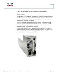
?XR Co municationsBA TERY UNITIMPORTANT SAFETY INSTRUCTIONSTotal <strong>Power</strong> OFF ProcedureWARNING!Before electrical installation begins, verify that the UPS is in the Total <strong>Power</strong> Off modeby following this procedure.UPSINTE LIGENCE MODULE INTE LIGENCE MODULE1Set the SystemEnable Switch tothe STAND-BYposition.SYSTEMENABLECAUTION!To ensure solid stability, do not pull Battery Units outbeyond the Red Disconnect Line unless completelyremoving them from the enclosure.1Set the DC Disconnect onALL Battery Enclosures inyour configuration to theOFF position.DOCUMENT STORAGE<strong>Symmetra</strong>® <strong>PX</strong>10 - 40 kW, 2 0 VBasic Operation GuideBatteryEnclosure2Disconnect allBattery Units byremoving orpulling out to RedDisconnect Line.BATTERY UNIT3Set the upstream Utility<strong>Power</strong> to the OFF orLOCKED OUT position. Ifthe UPS has dual mainssupply, set both suppliesto the OFF or LOCKEDOUT position. Note: Followproper lock out tagprocedures.OFFONOFF<strong>Symmetra</strong> ® <strong>PX</strong> 10-80 kW, 208V – Operation & Maintenance Guide – 990-1430 REV01 3
IntroductionAfter the UPS has been wired electrically, it is ready for start-up. This guide will allow you to quicklystart up the UPS. It contains information on Safety, System Components, Securing the UPS, ModuleInstallation, Network Cable Installation, Start-Up Procedure, and Basic Troubleshooting.4 <strong>Symmetra</strong> ® <strong>PX</strong> 10-80 kW, 208V – Operation & Maintenance Guide – 990-1430 REV01
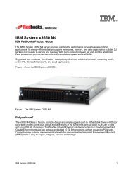
?Overview of System ComponentsIntelligenceModules (2)NetworkManagement CardCable<strong>Power</strong>ModuleBays<strong>Power</strong>ViewDisplay<strong>Power</strong> ModuleBatteryCommunicationCableBypass StaticSwitch ModuleSystem ID CardDOCUMENT STORAGE<strong>Symmetra</strong>® <strong>PX</strong>10 - 40 kW, 200 VBasic Operation GuideDocumentationStorage TrayInput /Output ChassisSystem <strong>Power</strong> SupplySystem<strong>Power</strong>SupplyCards (2)SystemEnable SwitchSYSTEMENABLEXR CommunicationRemote ComputerDisplay<strong>Power</strong> View InterfaceDisplay/Computer InterfacePort 1Port 2System <strong>Power</strong> SupplySmartSlots (2)Display / ComputerInterface CardBattery Comm CardTerminatorsResetPSU Sub Supply Switch Gear Monitor CardPSU SubSupplyLink RXTX10/10010/100Base-TStatusAP9617 Network Management CardSwitch GearMonitor CardNetworkManagementCard<strong>Symmetra</strong> ® <strong>PX</strong> 10-80 kW, 208V – Operation & Maintenance Guide – 990-1430 REV01 5
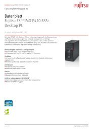
?Overview of System ComponentsWeightsUPS (empty)600 lb. (275 kg)<strong>Power</strong> Module60 lb. (26 kg)DOCUMENT STORAGE<strong>Symmetra</strong>® <strong>PX</strong>10 - 40 kW, 200 VBasic Operation Guide6 <strong>Symmetra</strong> ® <strong>PX</strong> 10-80 kW, 208V – Operation & Maintenance Guide – 990-1430 REV01
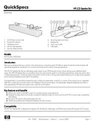
OperationThe <strong>Power</strong>View is the user control interface used to configure the functionality, monitor the system,set alarm thresholds, and to provide audible and visual alarms.Four LED indicatorsreport the operationalstatus of the UPS.Liquid crystaldisplay (LCD)Five navigation keys are used toselect and open menu items, toaccess information, change systemparameters, and to launch contextsensitivehelp.LOAD ONON BATTBYPASSChrg 100%Load 000%120Vin 000Vout 60HzRuntime: 00hr 30mESC?9FAULT123456 7 81234LOAD ON LEDON BATT LEDBYPASS LEDFAULT LEDWhen green, the <strong>Symmetra</strong> <strong>PX</strong> UPS is providing power to the loadequipment.When yellow, power is flowing from the batteries to the <strong>Power</strong> Modules.When yellow, power to the load is being supplied through the Static BypassSwitch.When red, an fault condition exists.5LCDDisplays alarms, status data, instructional help, and configuration items.67UP and DOWNnavigation keysENTER keySelects menu items and accesses information.Opens menu items and input changes to system parameters.89HELP keyESC keyLaunches context-sensitive help.Returns to previous screen displayed.<strong>Symmetra</strong> ® <strong>PX</strong> 10-80 kW, 208V – Operation & Maintenance Guide – 990-1430 REV01 7
OperationPress ESCESCsystem status information.until you get to the Top-Level Status Screen, which provides you with basicChrg 100%Load 000%120Vin 000Vout 60HzRuntime: 0hr 0mTop-Level Status Screen(factory default)Press Enter to open the Top-Level Menu screen. This screen is the launching pad tocommand, configure, and monitor the system.SelectorArrowControlStatusSetupAccessoriesLoggingDisplayDiagsHelpTop-Level MenuPress Up and Downto navigate the selector arrow and view all sub-menu screens.Bat Voltage: 218VBat Capacity 100.0%Runtime: 01hr 30min32 Batts, 00BadBattery Module Status ScreenCapacity: 80.0kVAFault Tolerance: n+1Total UPS Modules: 9Bad UPS Modules: 00<strong>Power</strong> Module Status ScreenScroll arrows indicate additional screensPress Up, Down and Enter to move input arrow to select and enterinformation.Low Batt Dur:Shutdwn Dly:Return Dly:Return Bat Cap:2min20sec0secLow Batt Dur:Shutdwn Dly:Return Dly:0% Return Bat Cap:Shutdown Menu10min20sec0sec0%Shutdown MenuInput arrows indicate changeable options8 <strong>Symmetra</strong> ® <strong>PX</strong> 10-80 kW, 208V – Operation & Maintenance Guide – 990-1430 REV01
OperationFunctional Schematic Dual Mains / Single MainsOnly present insingle mainsinstallations.Bypass InputMains InputBypass StaticSwitch Module<strong>Power</strong> ModuleLoadControl FunctionsTurn load on/off:1Graceful Turn OffStart Runtime CalTurn Load On2UPS LOAD IS OFFControl Sub-MenuLoad Off ScreenTurn into/out of bypass:1 UPS into BypassDo Self TestSimulate <strong>Power</strong> FailGraceful RebootControl Menu2UPS IS BYPASSEDBypassed Screen<strong>Symmetra</strong> ® <strong>PX</strong> 10-80 kW, 208V – Operation & Maintenance Guide – 990-1430 REV01 9
OperationControl ScreenFrom the Control screen, you can select the following items:UPS into BypassDo Self TestSimulate <strong>Power</strong> FailGraceful RebootGraceful Turn OffStart Runtime CalTurn Load On/OffPlace into or return from maintenance bypass operationInitiate a system of self-tests and diagnostics.Simulate a power failureTurn off and start load equipment in an ordinary manner.Shut down load equipment in an orderly manner.Begin runtime calibration of the UPS.Apply power to or shut down the <strong>Symmetra</strong> <strong>PX</strong> UPS10 <strong>Symmetra</strong> ® <strong>PX</strong> 10-80 kW, 208V – Operation & Maintenance Guide – 990-1430 REV01
OperationStatus FunctionsVerify general module status:Control LoggingCapacity: 80.0kVA1 Status Display 2 Fault Tolerance: n+1Setup DiagsTotal Pwr Modules: 9Accessories HelpBad Pwr Modules: 0Top-Level MenuSub-Sub-Sub-Sub-Sub Status ScreenVerify voltage on all phases:1ControlStatusSetupAccessoriesLoggingDisplayDiagsHelp20 Vin Vbyp Vout1 119.6 119.2 0.02 119.4 119.4 0.03 119.6 119.3 0.0Top-Level MenuStatus ScreenVerify battery voltage/capacity:1 2Control LoggingStatus DisplaySetup DiagsAccessories HelpTop-Level MenuBat Voltage: 218.6VBat Capacity: 100.0%Runtime: 1hr 30min32 Batts, 0 BadSub-Sub-Sub-Sub Status Screen<strong>Symmetra</strong> ® <strong>PX</strong> 10-80 kW, 208V – Operation & Maintenance Guide – 990-1430 REV01 11
OperationStatus screensThe status screen display information regarding load, battery, power module voltage, and current.Status Screen 1.VinVoutIoutThe input voltage (V), output voltage (V), and output current (A) for each phase(1-3).Status Screen 2.%load assuming noredundancyPercentage of the load in relation to the total capacity of all power modules.Status Screen 3.%load allowing forn+ redundancyPercentage of the load, allowing for the redundancy in your system.Status Screen 4.FrequenciesThe input and output frequency in hertz (Hz).Status Screen 5.Batt VoltageBatt CapacityRuntime#Batts#BadActual voltage of the DC bus (volts).Percentage of battery capacity availableThe available runtime for battery operation in hours and minutesThe number of installed battery modules.The number of failed battery modules.12 <strong>Symmetra</strong> ® <strong>PX</strong> 10-80 kW, 208V – Operation & Maintenance Guide – 990-1430 REV01
OperationStatus Screen 6.Capacity: kVAFault ToleranceTotal Pwr ModulesBad Pwr ModulesThe system load capacity.The configured redundancy for your UPS (n+0, n+1, n+2...).The number of power modules installedThe number of failed power modules installedStatus Screen 7.Alarm ThresholdsFault Tolerance n+0Runtime hr minload: kVASettings configured for the thresholds that trigger alarms.The alarm threshold for reduced redundancy.The alarm threshold for reduced runtime.Alarm indication of the load exceeding the configured redundancyStatus Screen 8.Self TestLst XfrStatusIMRIMStatus of the last self-testInformation on the last transfer to battery operation.General UPS status.Status of the main intelligence module.Status of the redundant intelligence module.Set-up FunctionsDisplay parameters are set to factory defaults.Changing factory default settings:Control Logging1 Status Display 2SetupAccessoriesDiagsHelpTop-Level MenuSettings:ShutdownDefaultsOutput FreqSettings MenuAlarmsBypassCopyOther<strong>Symmetra</strong> ® <strong>PX</strong> 10-80 kW, 208V – Operation & Maintenance Guide – 990-1430 REV01 13
OperationSetup screensFrom the Setup screen, you can select the following items:ShutdownConfigure the following system shutdown conditions:Low Batt Dur: Low battery duration is the time from low battery signal to theshutdown of the load. This signal is sent to the server using shutdown software(PC + PCNS).Shutdwn Dly: Shutdown delay is the time from when the UPS receives ashutdown command (usually sent by a server) to the shutdown of UPS power tothe load equipment. This delay allows load equipment time to finish shutdownprocesses.Return Dly: Return delay is the amount of time the UPS wants to turn on after apower outage has ended.DefaultsOutput FrequencyAlarmsReturn Bat Cap: Return battery capacity is the minimum percentage of batterycapacity required for the UPS to turn the load on.Return all UPS settings to their default values.Set the desired output frequencyRedundancy: The state of redundancy that will trigger an alarm. Choices are:• N+0 – an alarm will occur only when there is more load than all functioningpower modules can support;• N+1 – an alarm will occur when there are no spare power modules in goodcondition;• N+2 – an alarm will occur when there is only one functioning power module.Load: When the load is greater than this threshold, an alarm will sound.BypassCopyOtherRuntime: When the time the UPS can power the load is less than this threshold,an alarm will sound. This alarm is the result of an increase in load or a decrease inbattery capacity.Set the conditions in which the UPS will automatically go into bypass operation.Copy the UPS settings.Self Test: Set the UPS to perform a self-test automatically at periodic intervals.USP ID: Provide a unique name for the UPS.Vout Reporting: Set the reporting to the number of the tap to which the mostsignificant load is wired on the output transformer.Output: Set the UPS output voltage.BatFrAmpHour: Set the Ampere-Hour rating of external battery enclosures thatare not <strong>APC</strong> <strong>Symmetra</strong> <strong>PX</strong> Battery Enclosures.14 <strong>Symmetra</strong> ® <strong>PX</strong> 10-80 kW, 208V – Operation & Maintenance Guide – 990-1430 REV01
OperationAccessories screenControlStatusSetupAccessoriesTop-Level MenuLoggingDisplayDiagsHelpFrom the Accessories screen, you can view the status of <strong>APC</strong> accessories connected to the UPS.Logging ScreenControlStatusSetupAccessoriesTop-Level MenuLoggingDisplayDiagsHelpThe Logging screen allows you to customize the UPS log. The following items are accessible fromthis screen:View LogView StatisticsConfigure LoggingList Event GroupsPoint to an entry in the log and press the Enter key to view a description of theevent. The display logs the most recent 64 events.View statistics of the events logged.Set the type of events that are recorded in the log. To log a type of event, chooseOn.• View the list of event types.• <strong>Power</strong> Events• UPS Control Events• <strong>User</strong> Activities• UPS Fault Events• Measure UPS EventsFor each group, press the Enter key to display each event listed under the group.Clear LogClear all events currently stored in the log.<strong>Symmetra</strong> ® <strong>PX</strong> 10-80 kW, 208V – Operation & Maintenance Guide – 990-1430 REV01 15
OperationDisplay screensControlStatusSetupAccessoriesTop-Level MenuLoggingDisplayDiagsHelpThe Display screens allow you to customize the UPS display interface. The following items areaccessible from this screen:Date:PasswordInformationBeeperContrastConfigSet the correct date (day:month:year) and time (hour:minute).Protect the password against unauthorized configuration changes.View the model number, serial number, date of manufacture, and revision numberof the display interface.Configure the audible alarm interface.:At UPSAt DispVolClickSet the contrast on the LCD.Personalize the Top-Level Status screen. Choose each line you want displayedfrom a list of options. To change a line, move the selection arrow to the line youwant to change and press the ENTER key. Scroll up or down the list to find thedata you want displayed and press the ENTER key to save you changes. Press theESC key to discard your changes.Diag screensControlStatusSetupAccessoriesTop-Level MenuLoggingDisplayDiagsHelpThe Diagnostic screens provide information for use in troubleshooting. The following items areaccessible from this screen:16 <strong>Symmetra</strong> ® <strong>PX</strong> 10-80 kW, 208V – Operation & Maintenance Guide – 990-1430 REV01
DisplayDisplay/Computer InterfaceXR Co municationPort 1ResetLink-RX/TX10/1 010/1 0Base-TStatusAP9617 Network Management CardOperationFault & DiagnosticsLists any failures found.If any status except ON or OK is displayed, a module or card must be replaced.The Faults and diagnostics screen will describe the location of the failed module/card. If you do not have a redundant intelligence module installed, you must placethe UPS in bypass operation before you remove an intelligence module.Lists external device status.If any status except ON or OK is displayed, a module, card or battery must bereplaced. If you do not have a redundant intelligence module installed, you mustplace the UPS in bypass operation before you remove an intelligence module.Help screensTo access the display interface context-sensitive help screens, press the ? key.Network Connection/<strong>APC</strong> Web Management CardComputerInterfaceRemote Computer<strong>Power</strong> View Interface10/100Base-TResetLink-RX/TX10/100StatusAP9617 Network Management CardSerial portDOCUMENT STORAGE<strong>Symmetra</strong>® <strong>PX</strong>10 - 40 kW, 200 VBasic Operation Guide20-foot Network Cable supplied with the UPS.<strong>Symmetra</strong> ® <strong>PX</strong> 10-80 kW, 208V – Operation & Maintenance Guide – 990-1430 REV01 17
OperationQuick ConfigurationDisregard the procedures in this section if you have an <strong>APC</strong> InfrastruXure Manager aspart of your system. See the InfraStruXure Manager’s documentation for moreinformation.You must configure three TCP/IP settings before the Management Card can operate on a network:• IP address• Subnet mask• Default GatewayFrom the <strong>Power</strong>View Display:1ControlStatusSetupAccessoriesLoggingDisplayDiagsHelp2Web/SNMP Mngmnt CardNetwork SetupView Network SetupTop-Level MenuAccessories Menu3IP>>159.215.086.082Mask>>255.255.255.000Gway>>159.215.086.001Accept changes4IP>>159.215.086Mask>>255.255.255.000Gway>>159.215.086.001Accept changesNetwork Set-up ScreenNetwork Set-up ScreenIf a Default Gateway is unavailable, use the IP address of a computer located on the same subnetas the Management Card that is usually running. The Management Card uses the DefaultGateway to test the network when traffic is very light. See “Watchdog Features” in the“Introduction” of the Network Management Card <strong>User</strong>’s Guide CD (.\doc\usrguide.pdf) formore information about the watchdog role of the Default Gateway. The Management Card<strong>User</strong>’s Guide CD is located in the documentation storage tray.18 <strong>Symmetra</strong> ® <strong>PX</strong> 10-80 kW, 208V – Operation & Maintenance Guide – 990-1430 REV01
?XR Co municationsModule and Card ReplacementWARNING!Only trained persons familiar with the construction and operation of the equipment andthe electrical and mechanical hazards involved, may install and remove systemcomponents.How to replace <strong>Power</strong> Modules1INTE LIGENCE MODULE INTE LIGENCE MODULETo de-activate themodule, turn LockingLatch (with arrowpointing towards themodule) counterclockwiseuntil itpoints downwards.DOCUMENT STORAGE<strong>Symmetra</strong>® <strong>PX</strong>10 - 40 kW, 2 0 VBasic Operation Guide<strong>Symmetra</strong> ® <strong>PX</strong> 10-80 kW, 208V – Operation & Maintenance Guide – 990-1430 REV01 19
System <strong>Power</strong> SupplyXR CommunicationDisplayPort 1Remote<strong>Power</strong>View ComputerPort 2InterfaceSystem <strong>Power</strong> SupplyResetSwitch Gear Monitor CardStatusXR Co municationRemoteDisplay<strong>Power</strong>ViewDisplay / Computer InterfacePort 1Port 2?XR Co municationsModule and Card ReplacementUnscrew springactivatedknobs onboth sides of themodule until theypop out. Standingon either side of theUPS, 2 people cannow pull the modulealmost free ofthe UPS (the lockmechanism preventsthe modulefrom being pulledclear of the UPS).With the module stillresting in the UPS,release the lock bypushing the blackplastic tab on eitherside of the module22Pull out the module. Display showsmessage saying it has decreasedthe number of power modules.Reverse procedures for installation.INTE LIGENCE MODULE INTE LIGENCE MODULE3DOCUMENT STORAGE<strong>Symmetra</strong>® <strong>PX</strong>10 - 40 kW, 2 0 VBasic Operation Guide<strong>Power</strong> Module will not start unless Locking Latch is engaged.How to Replace CardsDisplay / Computer InterfacePSU Sub SupplyLink-RX/TX10/1 010/1 0Base-TDOCUMENT STORAGE<strong>Symmetra</strong>® <strong>PX</strong>10 - 40 kW, 2 0 VBasic Operation GuideAP9617 Network Management CardLoosen the 2 Phillips screws atboth sides of the card. Carefullypull out the card. Reverseprocedures for installation.Display shows message saying ithas registered the new card.System <strong>Power</strong> SupplyDisplayRemote<strong>Power</strong>ViewDisplay / Computer InterfaceXR CommunicationPort 1PSU Sub SupplyPort 2System <strong>Power</strong> SupplySwitch Gear Monitor Card20 <strong>Symmetra</strong> ® <strong>PX</strong> 10-80 kW, 208V – Operation & Maintenance Guide – 990-1430 REV01
Module and Card ReplacementHow to replace Intelligence ModulesOne intelligence module can be replaced without interrupting power to the connected equipmentprovided another functioning intelligence module is installed.Loosen the 2 Phillips screws at both sides of the module (top of module). As soon as the left side screw is loose, themodule will be deactivated. Display shows message saying it has decreased the number of cards. Reverse proceduresfor installation.INTE LIGENCE MODULE INTE LIGENCE MODULEINTELLIGENCE MODULE INTELLIGENCE MODULEHow to obtain replacement modulesTo obtain a replacement module, contact <strong>APC</strong> Customer Support at 1 (800) 800 4272.1. In the event of a module failure, the display interface may display additional “fault list” screens.Press any key to scroll through these fault lists, record the information, and relay it to therepresentative.2. If possible, call <strong>APC</strong> Customer Support from a telephone that is within reach of the <strong>Symmetra</strong><strong>PX</strong> UPS display interface so that you can gather and report additional information to therepresentative.3. Be prepared to provide a detailed description of the problem. A representative will help yousolve the problem over the telephone, if possible, or will give you a return materialauthorization (RMA) number. If a module is returned to <strong>APC</strong>, this RMA number must beclearly printed on the outside of the package.4. If the <strong>Symmetra</strong> <strong>PX</strong> UPS is within the warranty period, repairs will be performed free of charge.If it is not within the warranty period, there will be a charge for repair. Review <strong>APC</strong> ‘s warrantypolicy.<strong>Symmetra</strong> ® <strong>PX</strong> 10-80 kW, 208V – Operation & Maintenance Guide – 990-1430 REV01 21
Module and Card ReplacementSee section on Warranty for more information5. If the <strong>Symmetra</strong> <strong>PX</strong> UPS is covered by an <strong>APC</strong> service contract, have that information availableand give ti to the representative.Replacement Parts and NumbersPart80kW Enclosure Only10kW <strong>Power</strong> ModuleIntelligence Module<strong>Symmetra</strong> 3-Phase 80 kVA Bypass Static Switch ModuleSystem <strong>Power</strong> Supply CardPSU Supply BoardDisplay and Computer Interface CardSwitch Gear Monitoring CardSystem ID CardBattery Communication CardWeb Card, SNMPBattery Enclosure onlyNoSYCF80KFSYPM10KFSYMIM4SYSW80KFSYCSPSSYCSSSYCDCISYCSGMONSYCSYSIDSYCXRCOMAP9617 Web/Management Slot CardSYCF8BFWARNING!Only trained persons familiar with the construction and operation of the equipment, and theelectrical and mechanical hazards involved, may install and remove system components.22 <strong>Symmetra</strong> ® <strong>PX</strong> 10-80 kW, 208V – Operation & Maintenance Guide – 990-1430 REV01
TroubleshootingThis section lists all of the alarm and status messages that are displayed on the UPS display interface.A suggested corrective action is listed with each message to help you troubleshoot problems.If a problem is reported, ensure that the system component in question is correctly installed (referto section on Modular & Card Replacement.General StatusDisplay Message Meaning Corrective ActionInput Freq outsideconfigured rangeAC adequate for UPS butnot for bypassLow/No AC input,startup on batteryIntelligence ModuleinsertedIntelligence ModuleremovedRedundant IntelligenceModule insertedRedundant IntelligenceModule removedThe input frequency to the UPS isoutside the configured range. Theoutput frequency will not synchronizewith the input frequency.Normal bypass is not available.The <strong>Symmetra</strong> <strong>PX</strong> UPS will functiononline with the input voltage, but inthe event that bypass is required, theinput voltage is notadequate to power the loadequipment.Input voltage is not adequate to startthe <strong>Symmetra</strong> <strong>PX</strong> UPS. If start-upproceeds, the <strong>Symmetra</strong> <strong>PX</strong> UPS willfunction in battery operation.An Intelligence Module has beeninstalled into the <strong>Symmetra</strong> <strong>PX</strong> UPS.An Intelligence Module has beenremoved from the <strong>Symmetra</strong> <strong>PX</strong>UPS.An intelligence Module has beeninstalled into the <strong>Symmetra</strong> <strong>PX</strong> UPS.An Intelligence Module has beenremoved from the <strong>Symmetra</strong> <strong>PX</strong>UPS.Option 1: Improve the frequency ofthe incoming voltage.Option 2: Widen range of acceptableincomingfrequency using the display interface.Select Start-UP, Setup, OUtput, FreqSelect).Option 3:Proceed with startup. Normal bypassis not available.Option #1: Improve the incomingvoltage.Option #2: Proceed with startup.Normal bypass is not available.Option 1: Cancel start-up untilacceptable input voltage is present.No corrective action necessary.Check that the intelligence modulesare properly inserted and that thefastening screw is tight.No corrective action necessary.Check that the intelligence modulesare properly inserted and that thefastening screw is tight.<strong>Symmetra</strong> ® <strong>PX</strong> 10-80 kW, 208V – Operation & Maintenance Guide – 990-1430 REV01 23
TroubleshootingDisplay Message Meaning Corrective Action# of batteries changedsince last ON# of Pwr moduleschanged since last ONAt least one battery module has beenadded or removed from the UPS sincethe last time the <strong>Power</strong> ON commandwas used.At least one battery module has beenadded or removed from the UPS sincethe last time the Pwr ON commandwas used.Check that all battery units areinstalled correctly.Check that all power modules areproperly inserted, the two fasteningscrews are tight, and the locking latchis engaged.# of batteries increased At least on battery module has beenadded to the system.# of batteries decreased At least one battery module has beenremoved from the system.No corrective action necessary.Ensure that all battery units areproperly inserted.# of Pwr Modulesincreased# of Pwr Modulesdecreased# of External BatteryCabinets increased# of External Battery0Cabinets decreasedRedundancy RestoredAt least one power module has beenadded to the systemAt least one power module has beenremoved from the system.At least one external battery cabinethas been connected to the <strong>Symmetra</strong><strong>PX</strong> UPSAt least one external battery cabinethas been disconnected from the<strong>Symmetra</strong> <strong>PX</strong> UPSA loss of power module redundancyoccurred and the redundancy has beenrestored. Either additional moduleshave been installed or the load hasbeen reduced.No corrective action necessary.Check that all power modules areproperly inserted, the two fasteningscrews are tight, and the locking latchis engaged.No corrective action necessary.Ensure that all Battery Enclosure’scommunication cables are properlyconnected and that the LEDs areilluminated on the Batterycommunication cards.No corrective action necessary.24 <strong>Symmetra</strong> ® <strong>PX</strong> 10-80 kW, 208V – Operation & Maintenance Guide – 990-1430 REV01
TroubleshootingGeneral FaultDisplay Message Meaning Corrective ActionNeed Bat ReplacementThe Redundant IntelligenceModule is in controlUPS FaultOn BatteryShutdown or unable totransfer to batt due tooverloadLoad Shutdown fromBypass. Input Freq/Voltsoutside limitsFault, Battery ChargerFailureOne or more batterymodules are in need of replacementThe Main Intelligence Module hasfailed, and the redundant intelligencemodule is functioning as the primaryintelligence module.A fault has occurred in a power module.This will always occur with apower module failure message.The <strong>Symmetra</strong> <strong>PX</strong> UPS has transferredto battery operation due to theinput going out of acceptable range.At this time the batteries will dischargeuntil the input is restored to anacceptable range.The <strong>Symmetra</strong> <strong>PX</strong> UPS has shutdown because an overload occurredand bypass is not available.The <strong>Symmetra</strong> <strong>PX</strong> UPS has transferredto battery operation because theinput is out of acceptable range.The battery charger in one or more ofthe power modules failedRefer to Module Replacement Sectionfor procedures.Replace the Main Intelligence Module.Referto Module ReplacementSection for procedures.Contact <strong>APC</strong> Technical Support at (1)(800) 800-4272.No corrective action necessary.Note: Runtime is limited in duration.Prepare to shut down the <strong>Symmetra</strong><strong>PX</strong> UPS and the load equipment orrestore incoming voltage.Option 1: Reduce the load to eliminateoverload.Option 2: If possible, add powermodules to eliminate overload.Option 3: Replace failed power modulesto eliminate overload.Correct the input voltage problem.Refer to Module Replacement Sectionfor procedures.Fault, Internal Tempexceeded normal limitsInput circuit breakertripped openThe temperature of one or more batteryunits has exceeded system specifications.The input circuit breaker on the <strong>Symmetra</strong><strong>PX</strong> UPS is open. Input voltageis disconnected to the <strong>Symmetra</strong> <strong>PX</strong>UPS.Ensure that the ambient temperaturemeets the specifications of the system.Option 1: If this occurs with an overloadcondition, decrease the load andreset the breaker.Option 2: If no overload conditionexists, reset the breaker. If it tripsopen again, contact <strong>APC</strong> TechnicalSupport at (1) (800) 800-4272.System level fan failedA cooling fan in the <strong>Symmetra</strong> <strong>PX</strong>UPS failed.Contact <strong>APC</strong> Technical Support at (1)(800) 800-4272.<strong>Symmetra</strong> ® <strong>PX</strong> 10-80 kW, 208V – Operation & Maintenance Guide – 990-1430 REV01 25
TroubleshootingModule failureDisplay Message Meaning Corrective ActionBad Battery ModuleA battery module has failed andrequires replacement.Refer to Module Replacement Sectionfor procedures.Bad <strong>Power</strong> ModuleA power module has failed andrequires replacement.Refer to Module Replacement Sectionfor procedures.Intelligence Module isinstalled and failedThe Main Intelligence Module hasfailed and requires replacement.Replace the Main Intelligence Module.Refer to Module ReplacementSection for procedures.Redundant IntelligenceModule is installed andfailedThe Redundant Intelligence Modulehas failed and requires replacement.Replace the Redundant IntelligenceModule. Refer to Module ReplacementSection for procedures.Threshold AlarmDisplay Message Meaning Corrective ActionRedundancy has beenlostThe <strong>Symmetra</strong> no longer detectsredundant power modules. Eitherpower module(s) have failed, or theload has increased.Option 1: If possible, installadditional power modules.Option 2: Replace failed modules.Refer to Module Replacement Sectionfor procedures.Runtime is below alarmthresholdActual power module redundancy hasfallen below user-specifiedredundancy alarm threshold. Eitherpower module(s) failed or the loadincreased.Option 1: If possible, installadditional power modules.Option 2: Replace failed modules.Refer to Module Replacement Sectionfor procedures.Option 3: Decrease load orreconfigure threshold.Runtime is below alarmthresholdThe predicted runtime is lower thanthe user-specified minimum runtimealarm threshold. Either the batterycapacity has decreased, or the loadhas increasedOption 1: Allow the battery modulesto recharge.Option 2: If possible, increase thenumber of battery modules.Option 3: Reduce load or reconfigurethreshold.Load is above kW alarmthresholdThe load has exceeded the userspecified load alarm thresholdReduce load or re-configurethreshold.26 <strong>Symmetra</strong> ® <strong>PX</strong> 10-80 kW, 208V – Operation & Maintenance Guide – 990-1430 REV01
TroubleshootingDisplay Message Meaning Corrective ActionLoad is No Longer aboveAlarm ThresholdMin Runtime RestoredThe load exceeded the load alarmthreshold and the situation has beencorrected either because the loaddecreased or the threshold wasincreased.The system runtime dropped belowthe configured minimum and has beenrestored. Additional battery moduleswere installed, the existing batterymodules were recharged, the load wasreduced, or the threshold was raised.No corrective action necessaryNo corrective action necessaryBypassDisplay Message Meaning Corrective ActionBypass is not in range(either freq or voltage)Backfeed contactor stuckin OFF positionBackfeed contactor stuckin ON positionUPS in bypass due tointernal faultUPS in bypass due tooverloadSystem is inMaintenance bypassFault, Bypass RelayMalfunctionThe frequency and/orvoltage is out of acceptable range forbypass. This message occurs whenthe <strong>Symmetra</strong> is online, and indicatesthat the bypass mode may not beavailable if required.The <strong>Symmetra</strong> <strong>PX</strong> UPS is stuck in thebypass position and cannot go online.The <strong>Symmetra</strong> <strong>PX</strong> UPS is stuck in theon-line position and cannot go tobypass.The <strong>Symmetra</strong> <strong>PX</strong> UPS hastransferred to bypass mode because afault has occurredThe load exceeded the system powercapacity. The <strong>Symmetra</strong> <strong>PX</strong> UPS hasswitched to bypass modeThe <strong>Symmetra</strong> <strong>PX</strong> UPS is in bypassbecause it has been commanded intobypass or due to an internal fault.The bypass relay has malfunctioned.Option 1: Correct the input voltage toprovide acceptable voltage and/orfrequency.Option 2: Decrease the sensitivity toinput frequency. (Select Startup,Setup, OutputFreq, and select avalue).Contact <strong>APC</strong> Technical Support. at(1) (800) 800-4272.Contact <strong>APC</strong> Technical Support. at(1) (800) 800-4272.Contact <strong>APC</strong> Technical Support. at(1) (800) 800-4272.Option 1: Decrease the load.Option 2: If possible, add a powermodule to the system.No corrective action necessary. Ifother alarms exist, troubleshoot baseon other alarms.Contact <strong>APC</strong> Technical Support. at(1) (800) 800-4272.If the system works in bypass, ensure the presence of AC mains supply input.If a problem persists, note UPS model #, serial #, and date purchased before calling Tech Support at:1 (800) 800 4272.<strong>Symmetra</strong> ® <strong>PX</strong> 10-80 kW, 208V – Operation & Maintenance Guide – 990-1430 REV01 27
System Start-Up (if applicable)System start-up is included with your system. If you have to move your system to a new location andneed a new start-up, remove all power modules and follow the Total <strong>Power</strong> Off Procedure. Raise thestabilizing feet.Secure the UPS by Setting the Stabilizing FeetAfter the electrical wiring has been completed, secure the UPS in its final operating position. Use a13/14-mm wrench (shipped with UPS) to adjust all 4 stabilizing feet until pads make solid contactwith the floor.Level the UPS (Recommended)Adjust stabilizing feet to level from front to back and left to right.13/14-mm wrenchCAUTION!Do not move the UPS after the stabilizing feet have been lowered, or equipmentdamage may occur.28 <strong>Symmetra</strong> ® <strong>PX</strong> 10-80 kW, 208V – Operation & Maintenance Guide – 990-1430 REV01
?System Start-Up (if applicable)<strong>Power</strong> Module InstallationWARNING!Only <strong>APC</strong>-trained personnel familiar with the construction and operation of theequipment, and the electrical and mechanical hazards involved, may install and removesystem components.CAUTION!Before installing any modules in the UPS, ensure that the System Enable Switch is left in theSTAND-BY position (if not, see section on Total <strong>Power</strong> Off.At least 1 Battery Module (4 Battery Units) is required in the battery enclosure and theDC breaker to be on to start up the system. If using value line battery cabinets, batteryconfiguration will need to be entered manually through display,Installing9th8th7th6th5th4th3rd2nd1stStarting from thelowest available bay,remove as many blindplates as the number of<strong>Power</strong> Modules to beinstalled. Install <strong>Power</strong>Modules and pushcompletely into theUPS.DOCUMENT STORAGE<strong>Symmetra</strong>® <strong>PX</strong>10 - 40 kW, 200 VBasic Operation Guide<strong>Symmetra</strong> ® <strong>PX</strong> 10-80 kW, 208V – Operation & Maintenance Guide – 990-1430 REV01 29
?System Start-Up (if applicable)Securing1 2Fasten screws using ascrewdriver.Engage Locking Latch.Turn knob on right side ofUPS clockwise until arrowfaces module.DOCUMENT STORAGE<strong>Symmetra</strong>® <strong>PX</strong>10 - 40 kW, 2 0 VBasic Operation Guide3Make sure that theLocking Latch onBypass StaticSwitch Module isengaged.The <strong>Power</strong> Module will not start unless the Locking Latch is engaged.After the installation and securing of the <strong>Power</strong> Modules, make sure that the lockinglatch on the Bypass Static Switch Module is engaged30 <strong>Symmetra</strong> ® <strong>PX</strong> 10-80 kW, 208V – Operation & Maintenance Guide – 990-1430 REV01
?Network Cable Installation (if required)Use 20-ft. standard Cat 5 Data cable (supplied).WARNING!Ensure Total <strong>Power</strong> Off beforeremoving side panel3Unlock right-sidepanel using keyDepresslatches4INTE LIGENCE MODULE INTE LIGENCE MODULEPull out panel5Remove leftterminator fromPort I. Save forreinstallation inBattery Enclosure.Install BatteryCommunicationCable in Port I.ConnectBatteryCommCable toport 2.1DisplayDisplay / Computer InterfaceXR CommunicationsRemote<strong>Power</strong> ViewPort 1 Port 2ComputerInterfaceResetSwitch Gear Monitor CardDOCUMENT STORAGE<strong>Symmetra</strong>® <strong>PX</strong>10 - 40 kW, 2 0 VBasic Operation GuideLink-RX/TX10/10010/100Base-TStatusAP9617 Network Management2 Connect Network CommCable to Network Port as requiredLift panel off UPS6Route cablesthrough frontholes of UPS.Exit UPS frombottom or topas requiredIf your UPS has been installed in-between devices and side panels cannot be removedthe Bypass Static Switch Module can be removed to gain access.<strong>Symmetra</strong> ® <strong>PX</strong> 10-80 kW, 208V – Operation & Maintenance Guide – 990-1430 REV01 31
System Start-Up Procedure1Utility <strong>Power</strong> ON 2Battery EnclosureSwitch ON2System EnableSwitch ONONSYSTEMENABLEOFFWait approximately 30 seconds for system to boot up. Display will show a fault if<strong>Power</strong> Module Locking Latch is not engaged.PressESCstatus informationuntil you get to the Top-Level Status Screen, which provides you with basic systemLOAD ONON BATTBYPASSFAULTChrg 100%Load 000%120Vin 000Vout 60HzRuntime: 00hr 30mTop-Level Status ScreenESC?Press Enter to open the Top-Level Menu screen. This screen is the launching pad tocommand, configure, and monitor the system.ControlStatusSetupAccessoriesTop-Level MenuLoggingDisplayDiagsHelp32 <strong>Symmetra</strong> ® <strong>PX</strong> 10-80 kW, 208V – Operation & Maintenance Guide – 990-1430 REV01
System Start-Up ProcedurePress the down key and then the enter key to select Status. Verify that all power, batteryand intelligence modules are detected by the system and are functioning correctly by scrolling downand reviewing all status screens. Please note that the intelligence modules are monitored underthe “Miscellaneous” Status Screen (submenu under Status).Bat Voltage: 218VBat Capacity 100.0%Runtime: 01hr 30min32 Batts, 00BadTypical Status ScreenIf a problem is reported, ensure that the system component in question is correctlyinstalled. If the problem persists, refer to Basic Troubleshooting.From the Control Menu, choose Turn Load On.Load On LED should now be lit.Turn Load OnDo Self TestSimulate <strong>Power</strong> FailGraceful RebootControl Menu ScreenLOAD ONON BATTUPS Load is ON.BYPASSFAULTConfirm Menu ScreenThe UPS is now ready to support the load equipment.For further operation, <strong>Power</strong>View features, and configuration, see Basic OperationGuide and Product <strong>Manual</strong> CD (shipped with unit) and visit our website: www.apc.com.If you are using a network connection, please refer to the enclosed Product <strong>Manual</strong> CD.<strong>Symmetra</strong> ® <strong>PX</strong> 10-80 kW, 208V – Operation & Maintenance Guide – 990-1430 REV01 33
Life Support Policy/WarrantyLife Support PolicyAmerican <strong>Power</strong> Conversion Corporation, its affiliates and subsidiaries world-wide, (“<strong>APC</strong>”) do notrecommend the use of any of their products in life support applications where failure or malfunctionof the <strong>APC</strong> product can be reasonably expected to cause failure of the life support device or tosignificantly affect its safety or effectiveness. <strong>APC</strong> does not permit the use of any of its products indirect patient care. <strong>APC</strong> will not knowingly sell its products for use in such applications unless thelife support system or direct patient care device is part of a whole facility/building into which theUPS is integrated and unless <strong>APC</strong> receives in writing assurances satisfactory to <strong>APC</strong> that: (a) theUPS system will be configured in a manner that will provide N+1 power redundancy to the criticalload (b) the end-user assumes all risks and signs the <strong>APC</strong> System Configurations and Use Form, and(c) the customer and operators of the <strong>APC</strong> UPS system agree to idemnify and hold <strong>APC</strong> and itsaffiliates and subsidiaries harmless for any and all claims arising out of the systems use in suchapplications.Examples of devices considered to be life support devices include, but are not limited to, neonataloxygen analysers, nerve stimulators (whether used for anaesthesia, pain relief, or other purposes),autotransfusion devices, blood pumps, defibrillators, arrhythmia detectors and alarms, pacemakers,hemodialysis systems, peritoneal dialysis systems, neonatal ventilator incubators, ventilators for bothadults and infants, anaesthesia ventilators, infusion pumps, and any other device designated as“critical” by the U.S.F.D.A.Hospital grade wiring devices and leakage current may be ordered as options on many <strong>APC</strong> UPSsystems. <strong>APC</strong> does not claim that units with this modification are certified or listed as Hospital Gradeby <strong>APC</strong> or any other organization. Therefore these units do not meet the requirements for use indirect patient care.34 <strong>Symmetra</strong> ® <strong>PX</strong> 10-80 kW, 208V – Operation & Maintenance Guide – 990-1430 REV01
Life Support Policy/WarrantyFactory Warranty<strong>APC</strong> warrants that the unit, when properly installed and commissioned by <strong>APC</strong> or <strong>APC</strong> authorizedservice personnel, shall be free from defects in materials and workmanship for a period of (1) yearfrom the date of installation or maximum 18 months after manufacturing. In the event that the unitfails to meet the foregoing warranty, <strong>APC</strong> shall for a period of one (1) year repair or replace anydefective parts, without charge for on-site labor and travel if trained & authorized <strong>APC</strong> personnel hasconducted start-up of the unit.An <strong>APC</strong> Start-Up Service must be performed/completed by <strong>APC</strong> or by service personnel authorizedby <strong>APC</strong>. If not, the on-site factory warranty will be voided and replacement of defective parts onlywill be covered. <strong>APC</strong> shall have no liability and no obligation to repair the installed unit if nonauthorized<strong>APC</strong> personnel performed the start-up and such start-up caused the unit to be defective.<strong>APC</strong> SHALL NOT BE LIABLE UNDER THE WARRANTY IF ITS TESTING ANDEXAMINATION DISCLOSE THAT THE ALLEGED DEFECT IN THE PRODUCT DOES NOTEXIST OR WAS CAUSED BY PURCHASER’S OR ANY THIRD PERSON’S MISUSE,NEGLIGENCE, IMPROPER INSTALLATION OR TESTING, UNAUTHORIZED ATTEMPTS TOREPAIR OR MODIFY, OR ANY OTHER CAUSE BEYOND THE RANGE OF THE INTENDEDUSE, OR BY ACCIDENT, FIRE, LIGHTNING OR OTHER HAZARD.THERE ARE NO WARRANTIES, EXPRESSED OR IMPLIED, BY OPERATION OF LAW OROTHERWISE, OF PRODUCTS SOLD, SERVICED OR FURNISHED UNDER THISAGREEMENT OR IN CONNECTION HEREWITHIN. <strong>APC</strong> DISCLAIMS ALL IMPLIEDWARRANTIES OF MERCHANTABILITY, SATISFACTION AND FITNESS FOR APARTICULAR PURPOSE. <strong>APC</strong>’S EXPRESS WARRANTIES WILL NOT BE ENLARGED,DIMINISHED, OR AFFECTED BY AND NO OBLIGATION OR LIABILITY WILL ARISE OUTOF, <strong>APC</strong>’S RENDERING OF TECHNICAL OR OTHER ADVICE OR SERVICE INCONNECTION WITH THE PRODUCTS. THE FOREGOING WARRANTIES AND REMEDIESARE EXCLUSIVE AND IN LIEU OF ALL OTHER WARRANTIES AND REMEDIES. THEWARRANTIES SET FORTH ABOVE, CONSTITUTE <strong>APC</strong>’S SOLE LIABILITY ANDPURCHASER’S EXCLUSIVE REMEDY FOR ANY BREACH OF SUCH WARRANTIES. <strong>APC</strong>’SWARRANTIES RUN ONLY TO PURCHASER AND ARE NOT EXTENDED TO ANY THIRDPARTIES.IN NO EVENT SHALL <strong>APC</strong>, ITS OFFICERS, DIRECTORS, AFFILIATES OR EMPLOYEES BELIABLE FOR ANY FORM OF INDIRECT, SPECIAL, CONSEQUENTIAL OR PUNITIVEDAMAGES, ARISING OUT OF THE USE, SERVICE OR INSTALLATION, OF THEPRODUCTS, WHETHER SUCH DAMAGES ARISE IN CONTRACT OR TORT, IRRESPECTIVEOF FAULT, NEGLIGENCE OR STRICT LIABILITY OR WHETHER <strong>APC</strong> HAS BEEN ADVISEDIN ADVANCE OF THE POSSIBILITY OF SUCH DAMAGES.<strong>Symmetra</strong> ® <strong>PX</strong> 10-80 kW, 208V – Operation & Maintenance Guide – 990-1430 REV01 35
<strong>APC</strong> Worldwide Customer SupportCustomer support for this or any other <strong>APC</strong> product is available at no charge in any of the following ways:• Visit the <strong>APC</strong> Web site to find answers to frequently asked questions (FAQs), to access documentsin the <strong>APC</strong> Knowledge Base, and to submit customer support requests.– www.apc.com (Corporate Headquarters)Connect to localized <strong>APC</strong> Web sites for specific countries, each of which provides customersupport information.– www.apc.com/support/Global support with FAQs, knowledge base, and e-support.• Contact an <strong>APC</strong> Customer Support center by telephone or e-mail.– Regional centers:<strong>APC</strong> headquarters U.S., CanadaLatin AmericaEurope, Middle East, Africa(1) (800) 800-4272 (toll free)(1) (401) 789-5735 (USA)(353) (91) 702020 (Ireland)Japan (0) 3 5434-2021– Local, country-specific centers: go to www.apc.com/support/contact for contact information.Contact the <strong>APC</strong> representative or other distributor from whom you purchased your <strong>APC</strong> product forinformation on how to obtain local customer support.Entire contents copyright © 2003 American <strong>Power</strong> Conversion. All rights reserved.Reproduction in whole or in part without permission is prohibited. <strong>APC</strong>, the <strong>APC</strong> logo,<strong>Symmetra</strong>, and InfraStruXure are trademarks of American <strong>Power</strong> Conversion Corporationand may be registered in some jurisdictions. All other trademarks, product names, andcorporate names are the property of their respective owners and are used for informationalpurposes only.990-1430 05/2003