42" LCD Display Monitor - Mitsubishi Presentation Products
42" LCD Display Monitor - Mitsubishi Presentation Products
42" LCD Display Monitor - Mitsubishi Presentation Products
Create successful ePaper yourself
Turn your PDF publications into a flip-book with our unique Google optimized e-Paper software.
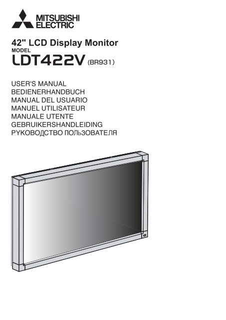
42" <strong>LCD</strong> <strong>Display</strong> <strong>Monitor</strong>MODEL
IndexFeatures ................................................................................................................................................................................... English-2Important Information .............................................................................................................................................................. English-3Declaration ............................................................................................................................................................................... English-5Safety Precautions, Maintenance & Recommended Use ....................................................................................................... English-6Contents ................................................................................................................................................................................... English-7Parts Name and Functions ....................................................................................................................................................... English-8Buttons, Switch, and Indicator .................................................................................................................................. English-8Connectors and Terminals ........................................................................................................................................ English-9Wireless Remote Control .......................................................................................................................................... English-10How to Use the Wireless Remote Control ................................................................................................................ English-11Preparation for use .................................................................................................................................................................. English-12Flow of preparation ................................................................................................................................................... English-12[P-1] Preparation for installation ............................................................................................................................................ English-13Determine the installation location ............................................................................................................................ English-13Ventilation requirements for enclosure mounting ..................................................................................................... English-13[P-2] Installing the monitor ..................................................................................................................................................... English-14Installing and removing the stands ........................................................................................................................... English-14Installing the main switch cover ................................................................................................................................ English-14Using the wall mount or ceiling mount ...................................................................................................................... English-14Installing in the portrait position ................................................................................................................................English-15[P-3] Installing the speakers .................................................................................................................................................. English-16[P-4] Connection procedure .................................................................................................................................................. English-17Wiring diagram .......................................................................................................................................................... English-17Prevention of disconnection of HDMI cable ............................................................................................................. English-17Connecting with a computer (analog connection) .................................................................................................... English-18Connecting with a computer (digital connection) ..................................................................................................... English-19Connecting a video device (component video/HDMI device) .................................................................................. English-20Connecting a video device (composite video/S video device)/stereo amplifier ...................................................... English-21[P-5] Connecting the power cord to the monitor .................................................................................................................. English-22Connecting the power source ................................................................................................................................... English-22How to Use ............................................................................................................................................................................... English-23Flow of How to Using ................................................................................................................................................ English-23[U-1] Turning on all the connected devices ........................................................................................................................... English-24Turning on external devices ...................................................................................................................................... English-24Turning on the monitor .............................................................................................................................................. English-24Power Management Function ................................................................................................................................... English-24[U-2] Selecting the video input .............................................................................................................................................. English-25[U-3] Controlling the external devices ................................................................................................................................... English-26[U-4] Auto-setup .................................................................................................................................................................... English-26[U-5] Selecting the picture mode ........................................................................................................................................... English-26[U-6] Screen adjustment ........................................................................................................................................................ English-27[U-7] Picture adjustment ........................................................................................................................................................ English-27[U-8] Volume control .............................................................................................................................................................. English-28[U-9] Schedule setting ........................................................................................................................................................... English-28How to set up schedule ............................................................................................................................................. English-29[U-10] Remote control .............................................................................................................................................................. English-30RS-232C Remote control .......................................................................................................................................... English-30Configuration and basic operation of OSD screen ................................................................................................................. English-32Configuration of OSD screen .................................................................................................................................... English-32Basic operation of OSD ............................................................................................................................................. English-33OSD screen functions .............................................................................................................................................................. English-34Other functions ........................................................................................................................................................................ English-42Selecting a video source ........................................................................................................................................... English-42Picture size ................................................................................................................................................................ English-42Picture mode ............................................................................................................................................................. English-42Audio input change ................................................................................................................................................... English-42OSD information ........................................................................................................................................................ English-42Control Lock mode .................................................................................................................................................... English-42PIP, POP function ...................................................................................................................................................... English-43Troubleshooting ....................................................................................................................................................................... English-44Specifications .......................................................................................................................................................................... English-45Pin Assignment ........................................................................................................................................................................ English-46EnglishEnglish-1
FeaturesFull 1920 x 1080 High-definition Resolution Page 45The LDT422V panel reproduces images from video and computer signals with precision and clarity, delivering full 1920 x 1080 highdefinitionresolution. The high-durability panel reduces the risk of image persistence in commercial applications.Wide-range Color Temperature Adjustment Page 34The display color temperatures can be adjusted from 2,600 K to 10,000 K. Such a wide range adjustment is important for industriessuch as broadcasters and food retailers where color accuracy and flesh tones are critical.Tiling Capability with Frame compensation Page 39Up to 25 panels (5 wide x 5 high) can be combined to create a single large image (i.e., video wall) or other high-impact signage. Aframe compesation function is incorporated to compensate the width of panel bezels so that images are displayed with the utmostaccuracy.PiP, PoP and Side-by-side Pages 37 and 43Picture-in-Picture and Picture-out-of-Picture are available when you want to display video content from a video input source in thesub picture and display the PC input source in the main picture, and vice versa.The native resolution as high as 1920 x 1080 can display these two input sources in the Side-by-side mode, ideal for broadcastingand video-conferencing applications.Programmable Scheduling Function Page 38The monitor’s operating schedule can be programmed for up to seven different scheduled time intervals by time, day of the weekand input port. This allows video content from different inputs to be displayed on certain monitors within the same installationaccording to the schedule, and extends the monitor’s life and saves the power by turning it off during those hours or days it is not inuse.Screen-saver Functions Page 40To reduce image persistence and maximize the panel life in demanding signage applications, the LDT Series is equipped with fourscreen-saver functions.• GAMMA• COOLING FAN• BRIGHTNESS• MOTIONSide Border Color Select Page 40When the 4:3 screen is displayed, the side border color can be selected from black, gray and white.Power-on Delay Page 39For installations employing numerous monitors, the power-on delay function can power up the monitors sequentially with delaybetween 2-50 seconds after the power is applied. Using this function can prevent inrush current problems and reduce the overallelectrical load requirements when a single power supply is used.Flexible Landscape & Portrait Positioning Page 15Designed to enhance for heat dissipation and long-term reliability in both landscape (horizontal) and portrait (vertical) positions.Closed Caption Page 39You can display captions.When closed-caption video signals are input, you can select to display or hide the captions on the screen.This monitor is compliant with EIA-608-A.English-2
Important InformationDECLARATION OF CONFORMITYThis device complies with Part 15 of FCC Rules. Operation is subject to the following two conditions. (1) This device may notcause harmful interference, and (2) this device must accept any interference received, including interference that may causeundesired operation.U.S. Responsible Party: <strong>Mitsubishi</strong> Digital Electronics America, Inc.Address:9351 Jeronimo Road,Irvine, California 92618 U.S.A.Tel. No.: +1 - (949) 465-6000Type of Product: Computer <strong>Monitor</strong>Equipment Classification: Class B PeripheralModel:LDT422V (BR931)EnglishWe hereby declare that the equipment specified aboveconforms to the technical standards as specified in the FCC Rules.Windows is a registered trademark of Microsoft Corporation. All other brands and product names are trademarks orregistered trademarks of their respective owners.HDMI, the HDMI logo and High-Definition Multimedia Interface are trademarks or registered trademarks of HDMI LicensingLLC.Canadian Department of Communications Compliance StatementDOC: This Class B digital apparatus meets all requirements of the Canadian Interference-Causing Equipment Regulations.C-UL: Bears the C-UL Mark and is in compliance with Canadian Safety Regulations according to CAN/CSA C22.2No. 60950-1.FCC Information1. Use the attached specified cables with this equipment so as not to interfere with radio and television reception.(1) The power supply cord you use must have been approved by and comply with the safety standards of U.S.A.,(2) Please use the supplied shielded video signal cable. Use of other cables and adapters may cause interference with radio andtelevision reception.2. This equipment has been tested and found to comply with the limits for a Class B digital device, pursuant to part 15 of theFCC Rules. These limits are designed to provide reasonable protection against harmful interference in a residential installation.This equipment generates, uses, and can radiate radio frequency energy, and, if not installed and used in accordance with theinstructions, may cause harmful interference to radio communications. However, there is no guarantee that interference will notoccur in a particular installation. If this equipment does cause harmful interference to radio or television reception, which can bedetermined by turning the equipment off and on, the user is encouraged to try to correct the interference by one or more of thefollowing measures:• Reorient or relocate the receiving antenna.• Increase the separation between the equipment and receiver.• Connect the equipment into an outlet on a circuit different from that to which the receiver is connected.• Consult your dealer or an experienced radio/TV technician for help.3. You are cautioned that changes or modifications not expressly approved by the party responsible for compliance could voidyour authority to operate the equipment.English-3
Important Information (continued)WARNINGTO PREVENT FIRE OR SHOCK HAZARDS, DO NOT EXPOSE THIS UNIT TO RAIN OR MOISTURE. ALSO, DO NOT USE THIS UNIT’SPOLARIZED PLUG WITH AN EXTENSION CORD RECEPTACLE OR OTHER OUTLETS UNLESS THE PRONGS CAN BE FULLY INSERTED.REFRAIN FROM OPENING THE CABINET AS THERE ARE HIGH VOLTAGE COMPONENTS INSIDE.REFER SERVICING TO QUALIFIED SERVICE PERSONNEL.CAUTIONCAUTION:TO REDUCE THE RISK OF ELECTRIC SHOCK, MAKE SURE POWER CORD IS UNPLUGGED FROM WALL SOCKET. TOFULLY DISENGAGE THE POWER TO THE UNIT, PLEASE DISCONNECT THE POWER CORD FROM THE AC OUTLET. DONOT REMOVE COVER (OR BACK). NO USER SERVICEABLE PARTS INSIDE. REFER SERVICING TO QUALIFIED SERVICEPERSONNEL.This symbol warns user that uninsulated voltage within the unit may have sufficient magnitude to cause electric shock.Therefore, it is dangerous to make any kind of contact with any part inside this unit.This symbol alerts the user that important literature concerning the operation and maintenance of this unit has beenincluded. Therefore, it should be read carefully in order to avoid any problems.CAUTIONThis <strong>LCD</strong> <strong>Monitor</strong> uses a lamp that contains mercury. Disposal of the lamp or the <strong>LCD</strong> <strong>Monitor</strong> with the lamp may beregulated due to environmental considerations. For disposal or recycling information, please contact your local authorities orthe Electronic Industries Alliance: www.eiae.org. (For US only).English-4
DeclarationDeclaration of the ManufacturerWe hereby certify that the color monitor LDT422V (BR931)is in compliance withCouncil Directive 2006/95/EC:— EN 60950-1Council Directive 2004/108/EC:— EN 55022— EN 61000-3-2— EN 61000-3-3— EN 55024and marked with<strong>Mitsubishi</strong> Electric Corporation2-7-3, Marunouchi,Chiyoda-KuTokyo 100-8310, JapanEnglishWarningThis is a Class A product. In a domestic environment this product may cause radio interference, in which case theuser may be required to take adequate measures.Declaration of the ManufacturerNote: This symbol mark is for EU countries only.This symbol mark is according to the directive 2002/96/EC Article 10 Information for users andAnnex IV, and/or to the directive 2006/66/EC Article 20 Information for end-users and Annex II.Your MITSUBISHI ELECTRIC product is designed and manufactured with high quality materials andcomponents which can be recycled and/or reused.This symbol means that electrical and electronic equipment, batteries and accumulators, at their end-of-life,should be disposed of separately from your household waste.If a chemical symbol is printed beneath the symbol shown above, this chemical symbol means that thebattery or accumulator contains a heavy metal at a certain concentration. This will be indicated as follows:Hg: mercury (0,0005%), Cd: cadmium (0,002%), Pb: lead (0,004%)In the European Union there are separate collection systems for used electrical and electronic products,batteries and accumulators.Please, dispose of this equipment, batteries and accumulators correctly at your local community wastecollection/recycling centre.Please, help us to conserve the environment we live in!English-5
Safety Precautions, Maintenance & Recommended UseFOR OPTIMUM PERFORMANCE, PLEASE NOTETHE FOLLOWING WHEN SETTING UP AND USINGTHE <strong>LCD</strong> COLOR MONITOR:• DO NOT REMOVE MONITOR BACK COVER. There areno user serviceable parts inside and opening or removingcovers may expose you to dangerous shock hazards orother risks.Refer all servicing to qualified service personnel.• Do not spill any liquids into the cabinet or use your monitornear water.• Do not insert objects of any kind into the cabinet slots,as they may touch dangerous voltage points, which canbe harmful or fatal or may cause electric shock, fire orequipment failure.• Do not place any heavy objects on the power cord.Damage to the cord may cause shock or fire.• Do not place this product on a sloping or unstable cart,stand or table, as the monitor may fall, causing seriousdamage to the monitor.• When operating the <strong>LCD</strong> monitor with its AC 100-120 Vpower supply in North America, use a power supply cordprovided with the monitor.• When operating the <strong>LCD</strong> monitor with its AC 220-240 Vpower supply in Europe, use a power supply cord providedwith the monitor.• In UK, use a BS-approved power cord with molded plughaving a black (10 A) fuse installed for use with this monitor.If a power cord is not supplied with this monitor, pleasecontact your supplier.• When operating the <strong>LCD</strong> <strong>Monitor</strong> with a 220-240 V ACpower supply in Australia, use the power cord provided withthe monitor.If a power cord is not supplied with this equipment, pleasecontact your supplier.• For all other cases, use a power cord that matches the ACvoltage of the power outlet and has been approved by andcomplies with the safety standard of your particular country.• Do not place any objects onto the monitor and do not usethe monitor outdoors.• The inside of the fluorescent tube located within the <strong>LCD</strong>monitor contains mercury. Please follow the bylaws or rulesof your municipality to dispose of the tube properly.• Do not bend power cord.• Do not use monitor in high temperature, humid, dusty, oroily areas.• If monitor or glass is broken, do not come in contact withthe liquid crystal and handle with care.• If the <strong>LCD</strong> monitor is damaged and the liquid crystal leaksout, do not inhale or swallow it.• Allow adequate ventilation around the monitor, so that heatcan properly dissipate. Do not block ventilated openings orplace the monitor near a radiator or other heat sources.Do not put anything on top of the monitor.• The power cable connector is the primary means ofdetaching the system from the power supply. The monitorshould be installed close to a power outlet, which is easilyaccessible.• Handle with care when transporting. Save packaging fortransporting.• Please clean the holes of back cabinet to reject dirt anddust at least once a year because of set reliability.• If using the cooling fan continuously, it’s recommended towipe holes a minimum of once a month.• When installing the remote control batteries;- Align the batteries according to the (+) and (-) indicationsinside the case.- Align the (-) indication of the batteries first inside thecase.CAUTION:Immediately unplug your monitor from the wall outlet and referservicing to qualified service personnel under the followingconditions:• When the power supply cord or plug is damaged.• If liquid has been spilled, or objects have fallen into themonitor.• If the monitor has been exposed to rain or water.• If the monitor has been dropped or the cabinet damaged.• If the monitor does not operate normally by followingoperating instructions.Recommend UseCAUTION:• For optimum performance, allow 20 minutes for warm-up.• Rest your eyes periodically by focusing on an object at least5 feet away. Blink often.• Position the monitor at a 90° angle to windows and otherlight sources to minimize glare and reflections.• Clean the <strong>LCD</strong> monitor surface with a lint-free, non-abrasivecloth. Avoid using any cleaning solution or glass cleaner!• Adjust the monitor’s brightness, contrast, and sharpnesscontrols to enhance readability.• Avoid displaying fixed patterns on the monitor for longperiods of time to avoid image persistence (after imageeffects).• Get regular eye checkups.ErgonomicsTo realize the maximum ergonomic benefits, we recommendthe following:• Use the preset Size and Position controls with standardsignals.• Use the preset Color Setting.• Use non-interlaced signals.• Do not use primary color blue on a dark background, asit is difficult to see and may produce eye fatigue due toinsufficient contrast.English-6
ContentsYour <strong>LCD</strong> monitor (LDT422V) comes with the following:English User’s Manual Video Signal Cable(Mini D-SUB 15-pin toMini D-SUB 15-pin Cable) <strong>LCD</strong> <strong>Monitor</strong> Screw (M4x8) x 2(For Clamper) Clamper x 2(For securing the powercord and HDMI cable) Clamper x 2(To prevent from falling)* The supplied power cord varies depending on destination. Screw (3x6) x 2(To fix Main switch cover) Power CordFor EU Power CordFor North America* For the use in the other regions, use a power cord thatmatches the AC voltage of the power outlet and has beenapproved by and complies with the safety standard of thoseregions or countries. Main switch cover Wireless RemoteControl and AAABatteriesThe following components are supplied as option.• External Speakers• StandsEnglish-7
Parts Name and FunctionsButtons, Switch, and IndicatorButton LocationEXIT INPUT MUTEOFFON1 Main Power SwitchSwitches the main power on/off.2 Remote control sensor and Power indicatorRemote control sensor: Receives the signal from the wirelessremote control.Power indicator: Indicates the state of the <strong>LCD</strong> monitor.• Steady green: The power is on.• Steady red:The power is off.Some operations such as power-onare possible.• Steady green and red: The <strong>LCD</strong> monitor is in the sleepmode.• Off:The main power is off.• Steady red and blinking green: The <strong>LCD</strong> monitor is in theschedule standby mode.• Blinking red:The <strong>LCD</strong> monitor has an error(detected by the self-diagnosticfunction).3 POWER button ( )Switches the power on/off.This button doesn’t work when the power indicator is off.Turn on the main power. (See page 24.)4 MUTE buttonSwitches the audio mute on/off.5 INPUT button<strong>Display</strong>s the OSD menu to switch the video input.You can select [RGB1], [RGB2], [RGB3], [RGB4], [DVD/HD],[VIDEO], or [VIDEO] using the UP ( ) or DOWN ( ) button.6 PLUS (+) buttonActs as (+) button to increase the adjustment in the OSD menu.Increases the audio output level when the OSD menu is off.7 MINUS (-) buttonActs as (-) button to decrease the adjustment in the OSD menu.Decreases the audio output level when the OSD menu is off.8 UP ( ) buttonActivates the OSD menu when the OSD menu is off.Acts as button to move the highlighted area up to select anadjustment item in the OSD menu.9 DOWN ( ) buttonActivates the OSD menu when the OSD menu is off.Acts as button to move the highlighted area down to selectan adjustment item in the OSD menu.10 EXIT buttonActivates the OSD menu when the OSD menu is off.Acts as EXIT button to go back to the previous OSD menu.(Reference) Control Lock modeYou can lock the operation buttons. See page 42.NOTE:For details about the OSD menu operation using the buttons, see “Basic operation of OSD.” (See page 33.)English-8
Parts Name and Functions (continued)Connectors and TerminalsEnglishAnti-theft lock slotYou can insert a Kensingtonanti-theft lock key.RLOUTOUTHVININR B GCr/Pr Cb/Pb Y1 AC IN (3-pin, with earth terminal)Connects with the supplied power cord.2 EXTERNAL SPEAKER TERMINALConnects with the special stereo speakers (option).3 AUDIO INConnects with the audio output connector of externalequipment such as a computer, VCR, and DVD player.(a) AUDIO1: ø3.5 stereo mini-jack connector(b) AUDIO2: RCA connector(c) AUDIO3: RCA connector4 AUDIO OUT (RCA)Outputs the signal that is supplied to the selected AUDIO INconnector. Connects with an external audio amplifier, etc.5 VIDEO INPUT/OUTPUT (BNC/S connector)Connects with video equipment.S VIDEO IN: S-video input connector (MINI DIN 4-pin)VIDEO IN: BNC connectorVIDEO OUT: BNC connector6 RS-232C connector (D-SUB 9-pin)IN connector:Connects with the RS-232C OUT connector of a computer orother connected LDT422V.OUT connector:Connects with the RS-232C IN connector of other connectedLDT422V.7 RGB1 IN (HDMI)Connects with the digital video output of a computer, DVDplayer, etc.8 RGB OUT (MINI D-SUB 15-pin)Outputs the signal that is supplied to the RGB3 or RGB4 INconnector.9 RGB2 IN (DVI-D)Connects with the digital video output of a computer, etc.10 RGB3 IN (MINI D-SUB 15-pin)Connects with the analog video output of a computer, etc.11 RGB4 IN, DVD/HD IN (BNC)Connects with the analog video output of a computer, etc.12 Cable HolderHolds the connected cables.English-9
Parts Name and Functions (continued)Wireless Remote Control8 AUDIO INPUT buttonsSelect the audio input from [AUDIO1], [AUDIO2], [AUDIO3], and[HDMI]. Note that [VIDEO] and [VIDEO] cannot be selected.You can select [HDMI] only when the video input source is[RGB1].9 PIP (Picture-in-Picture) buttonsON/OFF button: Switches the PIP or POP mode on/off.INPUT button: Selects video to be displayed in the subpicture.CHANGE button: Changes the main picture with the subpicture.[Description]PIP: Picture-in-PictureThe sub picture is displayed within the main picture.POP: Picture-out-PictureThe sub picture is displayed to the bottom right of the mainpicture.SIDE BY SIDEThe main picture and the sub picture are displayed side byside.1 POWER buttonSwitches the power on/off.* When the Power indicator is not glowing, no controls willwork.2 INPUT buttonsSelect the input signal from [RGB1] (HDMI), [RGB2] (DVI-D),[RGB3] (D-SUB), [RGB4] (BNC), [DVD/HD] (YPbPr), [VIDEO],and [VIDEO].NOTE:The [CAT5] and [DISPLAY PORT] buttons don’t work.3 PICTURE MODE buttonSelects the picture mode from [HIGHBRIGHT], [STANDARD],[sRGB], and [CINEMA]. See page 26.HIGHBRIGHT: The brightness is maximized.STANDARD: Factory default setting.sRGB: Suitable for color matching with sRGBcompliantdevices.CINEMA: Suitable for viewing movies.4 DISPLAY button<strong>Display</strong>s the screen information. See page 42. When the remotecontrol mode is LOCK, you can set it back to NORMAL byholding down the DISPLAY button for at least 5 seconds (seepage 39).5 SET buttonAccepts the settings made in the OSD menu.6 MINUS button (-)Acts as (-) button to decrease the adjustment in the OSD menu.When the PIP mode is active, this button moves the sub pictureto the left.7 AUTO SETUP button<strong>Display</strong>s the auto setup menu. See pages 26 and 35.NOTE:When the screen size is [CUSTOM] or [REAL], the PIP and POPmodes don’t work.10 STILL buttonON/OFF button: Switches the still picture mode on/off.CAPTURE button: Captures the new picture.11 SIZE buttonSelects the picture size from [FULL], [NORMAL], [CUSTOM],[DYNAMIC], and [REAL]. See page 42.12 MENU buttonSwitches the OSD menu mode on/off.13 UP button ( )Acts as button to move the highlighted area up to selectan adjustment item in the OSD menu. When the PIP mode isactive, this button moves the sub picture up.14 PLUS button (+)Acts as (+) button to increase the adjustment in the OSD menu.When the PIP mode is active, this button moves the sub pictureto the right.15 EXIT button<strong>Display</strong>s the previous OSD menu.16 DOWN button ( )Acts as button to move the highlighted area down to selectan adjustment item in the OSD menu. When the PIP mode isactive, this button moves the sub picture down.17 MUTE buttonSwitches the mute function on/off.18 VOLUME buttons (VOL)Pressing the plus (+) side increases the audio output level.Pressing the minus (-) side decreases the audio output level.English-10
Parts Name and Functions (continued)How to Use the Wireless Remote ControlOperating Range of the Wireless RemoteControlPoint the wireless remote control toward the <strong>LCD</strong> monitor’sremote control sensor during button operation.Use the wireless remote control within a distance of about 7 mfrom the front of the <strong>LCD</strong> monitor’s remote control sensor andat a horizontal and vertical angle of within 30° within a distanceof about 3.5 m.Installing and removing the Wirelessremote control batteriesThe wireless remote control is powered by 1.5 V AAA batteries.How to install the batteries1. Unlock and pull up the cover in the arrow’s direction.2. Align the batteries according to the (+) and (-) indicationsinside the case.3. Replace the cover.EnglishHow to remove the batteries1. Unlock and pull up the cover in the arrow’s direction.2. Remove the batteries.CAUTION:The remote control system may not function when directsunlight or strong illumination strikes the remote control sensorof the <strong>LCD</strong> monitor, or when there is an object in the path.CAUTION:Incorrect use of batteries can result in leaks or explosion.Be careful especially about the following points.• Place “AAA” batteries matching the (+) and (-) signs on eachbattery to the (+) and (-) signs of battery compartment.• Do not mix battery types.• Do not combine new batteries with used ones. It causesshorter battery life or leakage of batteries.• Remove dead batteries immediately to prevent batteryliquid from leaking into the battery compartment. Don’ttouch exposed battery acid because it causes damage toyour skin.Handling the wireless remote control* Do not subject to strong shock.* Do not allow water or other liquid to splash on the wirelessremote control. If the wireless remote control gets wet, wipeit dry immediately.* Avoid exposure to heat and steam.* Other than to install the batteries, do not open the wirelessremote control.NOTE:If you do not use the wireless remote control for a long period,remove the batteries.English-11
Preparation for useFlow of preparationP-1 Preparation for installation- Determine the installation location- Ventilation requirements for enclosure mountingPage 13Carry out as necessaryP-2Installing the monitorPages 14 to 15- Installing and removing the stands (The stands are optionally available.)- Installing the main switch cover- Using the wall mount or ceiling mount- Installing in the portrait positionCarry out as necessaryP-3Installing the speakersPage 16P-4Connection procedure- Wiring diagram- Prevention of disconnection of HDMI cable- Connecting with a computer (analog connection)- Connecting with a computer (digital connection)- Connecting a video device (component video/HDMI device)- Connecting a video device (composite video/S video device)/stereo amplifierPages 17 to 21P-5Connecting the power cord to the monitor- Connecting the power sourcePage 22The monitor is ready for use.How to UsePage 23English-12
P-2 Installing the monitor Carry out as necessaryInstalling and removing the standsThe stands are available as option.Refer to the user’s manual of the stand for more information.Screw x 2(Accessories ofthe option stand)Option stand x 2(Longer portion comes to the front.)How to install the stands1. Turn the monitor off.2. Fasten screws on both sides of the monitor.Using the wall mount or ceiling mountLay the screen face downLay the protective sheet on a table, which was wrapped aroundthe monitor when it was packaged, beneath the screen surfaceso as not to scratch the screen surface.This device cannot be used or installed without the TabletopStand or other mounting accessory. Failure to follow the correctmounting procedures can result in damage to the equipment orinjury to the user or installer. Product warranty does not coverdamage caused by improper installation.Failure to follow these recommendations can void yourwarranty.Use M6 screws (having a length 10 mm longer than thethickness of the mounting bracket) and tighten them securely.Prevent the screws from loosening using spring washers, etc.MITSUBISHI ELECTRIC recommends using mounting interfacethat comply with TÜV-GS and/or UL1678 standard in NorthAmerica.511.5 511.5100 100100 100ProtectiveSheetNOTE:Install the stands so that their longer portions come to the front.How to remove the stands1. Spread the protective sheet on a flat surface, such as adesk.2. Place the monitor on the protective sheet.3. Remove the screws with a screwdriver and place them in asafe place for reuse.100 100307307Installing the main switch coverTo prevent unauthorized operation of the main power switch,attach the main switch cover, which is supplied as anaccessory.NOTE:With the main power switch cover in place, the main powerswitch cannot be turned off. Remove the main power switchcover in order to switch off the monitor.Screw x 2(Accessory)TableTabletop Stand(mm)CAUTION:For preventing the monitor from falling.• Install the monitor with metal brackets for wall orceiling installation (commercially available) on your ownresponsibility. For detailed procedures of installation, referto the instructions of the metal brackets.• To lessen the probability of injury and damage resultingfrom fall of the monitor in case of earthquake or otherdisaster, be sure to consult the bracket manufacturer forinstallation location.• To lessen the risk of falling of the monitor, threadcommercially available rope through the handles at theright and left of the monitor and secure the rope to the wallmount brackets or ceiling mount brackets.• Do not sleep where the monitor may topple over or fall incase of an earthquake or other disaster.Main switch cover(Accessory)English-14
P-2 Installing the monitor (continued) Carry out as necessaryInstalling in the portrait positionConditions:LDT422V can be installed in the portrait position, under thefollowing conditions:CAUTION:Portrait position is available only when the monitor is wallmountedor ceiling-mounted.The stands (legs) can not be fitted to the monitor in the portraitposition.Placing the monitor in the portrait position will shorten theaverage life of the <strong>LCD</strong> backlight.Operation Environment (Temperature) shall be limited, asshown below:EnglishOperation Environment:Temperature 5 - 35°C / 41 - 95°FHumidity20 - 80% (without condensation)Place the monitor in the position shown below.Do not place the monitor in landscape in any other manner thanshown.Optional speakers (SP-422V) can not be attached when the<strong>LCD</strong> monitor is installed in the portrait position.How to set-upThe “” logo should be on the LEFT side whenviewed from the front of the monitor.Landscape90° ClockwiseLDT422VlogoLDT422VEnglish-15
P-3 Installing the speakers Carry out as necessaryBefore connecting the signal cable to PC and Video• Optional speakers can be installed.• Please refer to user’s guide of the optional speakers for the detailed installation procedure.How to install the optional speakers1. Use the metal fittings and screws that are supplied with the option speakers.2. Connect the cord of the left speaker to the SPEAKER (S) terminal (L) on the monitor, and the cord of the right speaker to theSPEAKER (S) terminal (R).Left speakerRight speakerSPEAKER (S)(L)SPEAKER (S)(R)Red(+)/Black(-)To speaker terminal (L)Red(+)/Black(-)To speaker terminal (R)NOTE:The speaker cord has polarity (+ and -). Match the colors of the speaker terminal and the connector of the cord.CAUTION:Do not move the monitor with the speakers installed.The monitor and the speakers may be damaged and you may be injured if the monitor falls.English-16
GBVRHDVI IND-SUB INHDMID-SUB OUTRS-232C INRS-232C OUTVIDEO INVIDEO OUTS-VIDEOIN1IN2IN3OUTLRP-4 Connection procedureBefore making connections• First turn off the power of all the connected equipment before making connections.• Refer to the user manual of each piece of equipment.NOTE:Please use the audio cable without resistance when the audio output terminal of the audio device and PC is stereo mini-Jack.When the audio cable with resistance is used, the audio level may not be increased or no audio may be output.EnglishWiring diagram<strong>LCD</strong> monitor (rear)Personal computer(DVI-D, HDMI)<strong>LCD</strong> monitor (first monitor)Stereo amplifierDVD player (HDMI, BNC)Personalcomputer(Analog RGB)HD disk player (HDMI)External speakers<strong>LCD</strong> monitor (second monitor)VCR (RCA)Prevention of disconnection of HDMI cableThe HDMI cable must be secured by the clamper to prevent it from being disconnected accidentally.Clamper(Accessory)Cable HolderEnglish-17
GBVRHDVI IND-SUB INHDMID-SUB OUTRS-232C INRS-232C OUTVIDEO INVIDEO OUTS-VIDEOIN1IN2IN3OUTLRP-4 Connection procedure (continued)Connecting with a computer (analog connection)The monitor automatically distinguishes the timings shown in the table below and sets the screen information. When a PC or otherdevice is connected, it automatically displays images properly.ResolutionFrequencyFrequencyRemarksResolutionHorizontal Vertical Horizontal VerticalRemarks1 640 x 480 31.5 kHz 60 Hz 6 1280 x 1024 64.0 kHz 60 Hz2 800 x 600 37.9 kHz 60 Hz 7 1600 x 1200 75.0 kHz 60 Hz3 1024 x 768 48.4 kHz 60 Hz 8 1920 x 1080 67.5 kHz 60 Hz Recommend timing4 1280 x 768 48.0 kHz 60 Hz 9 1920 x 1200 74.0 kHz 60 Hz5 1360 x 768 47.7 kHz 60 HzNOTE:When a signal other than 1920x1080 is input, characters may be blurred and figures and objects may be distorted.Images may not be displayed correctly depending on the video card or driver being used.Analog connection:• Connection via RGB3 IN (D-SUB) connector(1) Connect an RGB cable (mini D-SUB 15-pin – mini D-SUB 15-pin) (accessory) to the RGB3 IN connector.(2) Select [RGB3] using the INPUT button on the monitor or the D-SUB button on the wireless remote control.• Connection via RGB4 IN (BNC: R•G•B•H•V, or R•G•B•Csync, RGB sync on green) connector(1) Use a BNC cable (BNC x 5 - BNC x 5) (commercially available) to connect the BNC connector on the PC, and use a signalcable (mini D-SUB 15-pin - BNC x 5) (commercially available) to connect the mini D-SUB 15-pin connector on the PC.(2) Select [RGB4] using the INPUT button on the monitor or the BNC button on the wireless remote control.Second monitor connection:• Connect the RGB OUT connector (mini D-SUB 15-pin) on the first monitor and the RGB3 IN connector (mini D-SUB 15-pin)on the second monitor using an RGB cable (mini D-SUB 15-pin - mini D-SUB 15-pin) (an accessory of the second monitor orcommercially available).(The RGB3 or RGB4 signal selected by the first monitor is output. The RGB1 or RGB2 signal isn’t output.)Audio connection:• Connect an audio cable (ø3.5 mm stereo mini) (commercially available) to the AUDIO IN1 connector.Select [AUDIO1] using the AUDIO INPUT buttons on the wireless remote control.• To output audio to the second monitor:Connect the AUDIO OUT connector on the first monitor and the AUDIO IN2 or 3 connector on the second monitor using an RCAcable (audio) (commercially available).<strong>LCD</strong> monitor (rear)Personal computer(Analog RGB)To BNC outputPersonal computer(Analog RGB)RGB4 IN (R,G,B,H,V)BNC cable(BNC x 5 to BNC x 5)RGB cable(Mini D-SUB 15-pin toMini D-SUB 15-pin)RGB3 IN (D-SUB)AUDIO IN1 (mini)To D-SUB outputTo audio outputAudio cable(ø 3.5 mm stereo mini)<strong>LCD</strong> monitor (first monitor)RGB3 IN (D-SUB)AUDIO IN2 (RCA)RGB cable(Mini D-SUB 15-pin toMini D-SUB 15-pin)RCA cable (audio)RGB OUT (D-SUB)AUDIO OUT (RCA)<strong>LCD</strong> monitor (second monitor)(Multi-connection)English-18
GBVRHDVI IND-SUB INHDMID-SUB OUTRS-232C INRS-232C OUTVIDEO INVIDEO OUTS-VIDEOIN1IN2IN3OUTLRP-4 Connection procedure (continued)Connecting with a computer (digital connection)Digital connection:• Connection via the RGB1 IN connector (HDMI)(1) Connect an HDMI cable (commercially available) to the RGB1 IN connector.(2) Select [RGB1] using the INPUT button on the monitor or the HDMI button on the wireless remote control.• Connection via the RGB2 IN connector (DVI-D)(1) Connect a DVI-D cable (commercially available) to the RGB2 IN connector.(2) Select [RGB2] using the INPUT button on the monitor or the DVI-D button on the wireless remote control.Audio connection:• Connect an audio cable (ø3.5 mm stereo mini) (commercially available) to the AUDIO IN1 connector.Select [AUDIO1] using the AUDIO INPUT buttons on the wireless remote control.When an HDMI cable is connected, select HDMI audio.(You can select HDMI only when the video input is [RGB1].)English<strong>LCD</strong> monitor (rear)Personal computer(DVI-D, HDMI)To DVI-D outputDVI-D cableHDMI cableTo HDMI outputRGB2 IN (DVI-D)RGB1 IN (HDMI)AUDIO IN1 (mini)Audio outputAudio cable(ø3.5 mm stereo mini)<strong>LCD</strong> monitor (first monitor)English-19
GBVRHDVI IND-SUB INHDMID-SUB OUTRS-232C INRS-232C OUTVIDEO INVIDEO OUTS-VIDEOIN1IN2IN3OUTLRP-4 Connection procedure (continued)Connecting a video device (component video/HDMI device)This monitor can be connected to a video device equipped with component output such as a DVD player.Refer to the user’s manual of the connected device for details. (Cables shown in the fi gure below are commercially available.)• To connect a DVD player equipped with component output to the DVD/HD IN connector (YPbPr or YCbCr) on the monitor, use aBNC cable (BNC x 3 – BNC x 3) and a BNC-RCA adaptor (commercially available), or a signal cable (BNC x 3 – D connector).Select [DVD/HD] using the INPUT button on the monitor or the YPbPr button on the wireless remote control.• To make audio connection, connect an RCA cable (audio) to the AUDIO IN2 connector or the AUDIO IN3 connector.Select [AUDIO2] or [AUDIO3] using the AUDIO INPUT buttons on the wireless remote control.• To connect a DVD player equipped with HDMI output to the RGB1 IN connector (HDMI) on the monitor, use an HDMI signalcable.Select [RGB1] using the INPUT button on the monitor or the HDMI button on the wireless remote control.• For HDMI cable connection, select HDMI audio.(You can select HDMI audio only when the video input is [RGB1].)Signal cable(BNC x 3 to D connector)To D connector output<strong>LCD</strong> monitor (rear)BNC cable(BNC x 3 to BNC x 3)To video outputDVD player(component device)BNC-RCA adaptorAudio outputRCA cable (audio)DVD/HD IN(Y·Pb·Pr, Y·Cb·Cr) AUDIO IN2 (RCA)DVD player(HDMI device)RGB1 IN (HDMI)HDMI cableTo HDMI outputEnglish-20
GBVRHDVI IND-SUB INHDMID-SUB OUTRS-232C INRS-232C OUTVIDEO INVIDEO OUTS-VIDEOIN1IN2IN3OUTLRP-4 Connection procedure (continued)Connecting a video device (composite video/S video device)/stereo amplifierThis monitor can be connected to a stereo amplifier.Refer to the user’s manual of the stereo amplifier for details. (Cables shown in the figure below are commercially available.)• To connect a video device to the VIDEO IN connector (VIDEO IN or S-VIDEO IN) on the monitor, use a BNC cable or an S videocable. For connection to the audio input connector on the monitor, use an RCA cable (audio cable). Connect the connectorsof the RCA cable (audio) correctly. For connection to the VIDEO IN connector, select [VIDEO] using the INPUT button on themonitor or the VIDEO button on the wireless remote control. For connection to the S-VIDEO IN connector, select [VIDEO]using the INPUT button on the monitor or the VIDEO(S) button on the wireless remote control.• When connecting a stereo amplifier to the monitor, be sure to turn off the power of the stereo amplifier. For connection to theaudio output connector on the monitor, use an RCA cable (audio). Connect the connectors of the RCA cable (audio) correctly. Besure to turn on the monitor first, and then turn on the stereo amplifier.• The selected audio input signal is output from the AUDIO OUT connector.English<strong>LCD</strong> monitor (rear)RCA cable (audio)S video cableS-VIDEO IN AUDIO IN2<strong>LCD</strong> monitor (first monitor)VIDEO INAUDIO OUTBNC cableVIDEO OUTTo Audio outputTo S video outputTo video outputRCA cable (audio)To Audio inputVideo device(composite video/S video device)BNC cableStereo amplifierVIDEO IN<strong>LCD</strong> monitor (second monitor)External speakerExternal speakerEnglish-21
P-5 Connecting the power cord to the monitorConnecting the power source• The power outlet socket should be installed as near the equipment as possible and should be easily accessible.• Fully insert the prongs into the power outlet socket.Loose connection may cause noise.NOTE:Please refer to “Safety Precautions, Maintenance & Recommended Use” in this manual for proper selection of the AC power cord.Clamper (Accessory)Cable holderUse the clamper to secure thecable firmly.Power cord (For EU)Power cord (For North America)English-22
How to UseFlow of How to UsingU-1Turning on all the connected devicesPage 24EnglishU-2Selecting the video inputPage 25U-3Controlling the external devicesPage 26RGB3 and RGB4 onlyU-4Auto-setupPage 26U-5Selecting the picture modePage 26U-6Screen adjustmentPage 27U-7Picture adjustmentPage 27Carry out as necessaryU-8Volume controlPage 28U-9Schedule settingPages 28 to 29U-10Remote controlPages 30 to 31English-23
U-1 Turning on all the connected devicesTurning on external devices1. Turn on the connected devices such asthe computer and VCR.Before turning on the monitor, turn on the computer.Turning on the monitor2. Turn on the Main Power Switch.The power indicator turns on green.The control buttons on the bottom of the monitor and thewireless remote control don’t work while the Main PowerSwitch is off (the power indicator is off).When using them, check that the Main Power Switch is on(the power indicator is on).3. When the power indicator glowsred, press the POWER button on themonitor.The power indicator turns green.Power Management FunctionThis function reduces the power consumption of the monitorwhen the keyboard or the mouse is not used for a fixed periodeven though the power of the monitor is on.While this function is working, the screen becomes dark andthe power indicator glows green and red.This function is available only when a computer equippedwith the VESA-approved DPM Power Management function isconnected to the monitor.Check that the power management function (power saver) forRGB is ON.When you turn on this function for VIDEO, the monitor goes intothe sleep mode in 10 minutes after RGB4, DVD/HD, VIDEO,or VIDEO sync signal is lost.[Description]DPM: Acronym for <strong>Display</strong> Power ManagementNOTE:The default power management settings (power savers) forRGB and VIDEO are ON.Power IndicatorStatusPower ONPower OFFPower Standby when“SCHEDULE” is enablePower StandbyDiagnosis (Detecting failure)orLEDGreenRedRed OnGreen BlinkingRed, GreenRed Blinking* See troubleshooting on page 44.Main Power SwitchPower buttonPower buttonWireless remotecontrolEnglish-24
U-2 Selecting the video inputYou can select the desired video input using the wireless remote control or the INPUT button on the monitor.1. Select using the INPUT buttons on the wireless remote control.You can select the desired video input by pressing the corresponding INPUT button on the wireless remote control.Selectable video inputs are [RGB1] (HDMI), [RGB2] (DVI-D), [RGB3] (D-SUB), [RGB4] (BNC), [DVD/HD] (YPbPr), [VIDEO](VIDEO(S)), and [VIDEO] (VIDEO).EnglishNOTE:The [CAT5] and [DISPLAY PORT] buttons don’t work.2. Select using the INPUT button on the monitor.When you press the INPUT button on the monitor, the video input OSD menu is displayed and you can select the video inputusing the and buttons.Selectable video inputs are [RGB1] (HDMI), [RGB2] (DVI-D), [RGB3] (D-SUB), [RGB4] (BNC), [DVD/HD], [VIDEO-S], and [VIDEO].RGB1RGB2RGB3RGB4DVD/HDVIDEO-SVIDEOINPUT buttonVideo input OSD menuSelect using the and buttons.English-25
U-3 Controlling the external devicesYou can control the externally connected devices to display images supplied from them.VCR, etc.Personal computerU-4 Auto-setup Analog inputs onlyThe AUTO SETUP button on the wireless remote control or AUTO SETUP in the OSD menu automatically adjusts the screen size,horizontal/vertical position, clock, clock phase, white level, and black level.NOTE:The auto setup works on RGB3 and RGB4 only.U-5 Selecting the picture modeUsing the PICTURE MODE button on the wireless remote control, you can select the picture mode suitable for images to bedisplayed.HIGHBRIGHT: The brightness is maximized.STANDARD: Factory default setting.sRGB: Suitable for color matching with sRGB-compliant devices.CINEMA: Suitable for viewing movies.English-26
U-6 Screen adjustmentWhen images aren’t displayed properly even after the auto setup, you can alternatively adjust the screen by pressing the MENUbutton on the wireless remote control or the control buttons on the bottom of the monitor to display the OSD menu. Using theSCREEN settings in the OSD menu, you can adjust the horizontal/vertical position, clock, clock phase, CUSTOM ZOOM, horizontalresolution, vertical resolution, and input resolution.NOTE:The position adjustment works on RGB3, RGB4, DVD/HD, VIDEO, and VIDEO only.The clock adjustment and the resolution adjustment work on RGB3 and RGB4 only.The zoom adjustment works on all video inputs.EnglishU-7 Picture adjustmentYou can adjust the picture by pressing the MENU button on the wireless remote control or the control buttons on the bottom ofthe monitor to display the OSD menu. Using the PICTURE settings in the OSD menu, you can adjust picture settings such as thebrightness, contrast, and sharpness.English-27
U-8 Volume control Carry out as necessaryWhen outputting audio from the option stereo speakers, you can control the volume level using the VOL button on the wirelessremote control.In addition, you can adjust the volume by pressing the MENU button on the wireless remote control or the control buttons on thebottom of the monitor to display the OSD menu. Using the AUDIO settings in the OSD menu, you can adjust the balance, treble, andbass.Volumecontrol<strong>Display</strong>ingthe OSDmenuU-9 Schedule setting Carry out as necessaryYou can program the power-on/off and input selection using the SCHEDULE setting in the OSD menu that is displayed by pressingthe MENU button on the wireless remote control or the control buttons on the bottom of the monitor.English-28
U-9 Schedule setting (continued) Carry out as necessaryHow to set up scheduleEnglishCheck boxRadio buttonWhen the cursor is on any of the check boxes showing the program numbers 1 to 7 on the left side of the screen, pressing the UP( ) or DOWN ( ) button moves the cursor vertically and pressing the PLUS (+) or MINUS (-) buttons moves it horizontally.By pressing the SET button, you can select or deselect the check boxes.Check box: When the check box is selected, the program is enabled. When it is cleared, the program is disabled.When the SCHEDULE screen is closed, the programs you made become enabled and will be executed at thespecified times.When the cursor is on any item of the schedule settings in the white frame, pressing the PLUS (+) button moves it to the right andpressing the MINUS (-) button moves it to the left.You can set the power-on/off time and video input by pressing the UP ( ) or DOWN ( ) button. You can select or deselect theradio buttons by pressing the SET button.ON: Set the time when the power is turned on. If you don’t want to set the power-on time, enter “--.”OFF: Set the time when the power is turned off. If you don’t want to set to the power-off time, enter “--.”INPUT: Set the video input to be selected when the power is turned on. If you want to select the vide input that wasselected before the power is turned on, enter “--.”EVERY DAY: Select this option to execute the schedule every day. When you select EVERY DAY, you cannot select any daysof the week and EVERY WEEK.MON - SUN: Select the days of the week on which you want to execute the schedule. Unless you select EVERY WEEK, too,the selection of the days of the week is cleared after the schedule is executed one time.EVERY WEEK: Select this option to execute the schedule on the selected days of the week, every week.NOTE:• Before making the schedule settings, be sure to check the current date and time using “DATE AND TIME.”• When you close the SCHEDULE screen, the settings are saved.• When two or more schedules are enabled, they are executed in descending order of the program number, and the power isturned off upon completion of the last executed schedule.• When there are two or more schedules having the same power-on/off time, the one having the largest program number isexecuted.• You cannot set the power-on time and the power-off time to the same time.• When OFF TIMER is ON, the schedule settings are ignored.English-29
U-10 Remote control Carry out as necessaryRS-232C Remote controlBy connecting multiple <strong>LCD</strong> monitors and a computer using RS-232C cables (commercially available), you can control the monitorsfrom the computer for the following operations:• Power ON or OFF• Switching input signalsConnection<strong>LCD</strong> monitor + PCTo RS-232CTo RS-232CTo RS-232CPCconnector INconnector OUTconnector INRS-232C cableRS-232C cable• Before making connections, turn off the personal computer and the monitors.• Start the personal computer first, and then turn on the monitors. (Otherwise, the com port may be unusable.)NOTE:For connection with a 25-pin serial port connector on the computer, a conversion adapter is required.Contact your dealer for details.1) InterfacePROTOCOLBAUD RATEDATA LENGTHPARITY BITSTOP BITFLOW CONTROLRS-232C9600 [bps]8 [bit]NONE1 [bit]NONEThis <strong>LCD</strong> monitor uses RXD, TXD and GND lines for RS-232C control.Use RS-232C cables of reverse type (commercially available).2) Control command diagramThe command is structured by the address code, function code, data code and end code. The length of the command isdifferent for each function.NOTE:The example below shows basic commands used for the configuration consisting of one computer and one monitor (one-to-oneconnection). For the commands for connecting multiple monitors, contact your dealer.Address code Function code Data code End codeHEX 30h 30h Function Data 0DhASCII ‘0’ ‘0’ Function Data[Address code] 30h 30h (ASCII code, ‘0’ ‘0’), fixed.[Function code] Code unique to each control function.[Data code] Data unique to each control function (Not always indicated by numerical values.)[End code] 0Dh (In ASCII code, ‘ ’) fixed.English-30
U-10 Remote control (continued) Carry out as necessary3) Control sequence(1) A command is sent from the computer to the monitor. (Commands should be sent at intervals of at least 600 ms.)(2) The monitor sends a return command within 600 ms* after receiving and encoding the command. If the monitor fails toreceive the command, it doesn’t send any return command.(3) The computer checks the return command to see that the command it sent was executed or not.(4) The monitor sends various codes other than the return code. While RS-232C control sequence is in progress, reject othercodes on the personal computer side.*: Transmission of the return command may be delayed during signal switchover, etc.Example: Turn the power ON (‘ ’ is for ASCII code)EnglishCommand from computer Command from monitor Detail of command30 30 21 0D‘0’ ‘0’ ‘!’ ‘ ’Command for POWER ON30 30 21 0DCommand received‘0’ ‘0’ ‘!’ ‘ ’ (Command echoed back)4) Operation commandsThe operation commands configure the basic operation settings of this <strong>LCD</strong> monitor. The commands may not work during signalswitchover.The operation commands have no data codes.Operation ASCII HEXPOWER ON ! 21hPOWER OFF " 22hINPUT RGB 1 _r1 5Fh 72h 31hINPUT RGB 2 _r2 5Fh 72h 32hINPUT RGB 3 _r3 5Fh 72h 33hINPUT RGB 4 _r4 5Fh 72h 34hINPUT VIDEO _v1 5Fh 76h 31hINPUT DVD/HD _v2 5Fh 76h 32hINPUT S-VIDEO _v3 5Fh 76h 33h• After sending the POWER ON or POWER OFF command, wait for at least 1 minute to send the next command.• After sending any of the video input selection commands, wait for at least 10 seconds to send the next command.5) Read commandThe computer sends the command without datacode to the monitor.After receiving this command, the monitor returns the command with datacode including the current status to the computer.Example: When the computer asks the power status of the monitor, and the status of the monitor is powered-on.Command from computer Command from monitor Detail of command30 30 76 50 0D ‘0’‘0’‘v’‘P’[enter] Ask about the power status of the monitor.30 30 76 50 31 0D ‘0’‘0’‘v’‘P’‘1’[enter] <strong>Monitor</strong> is powered-on.Structure of the Read-commandPOWERInputPicture modeInternaltemperatureASCIIHEXFunction Data (Receive) Function Data (Receive)ON vP 1 76 50 31OFF (stand by) vP 0 76 50 30RGB-1 (HDMI) vI r1 76 49 72 31RGB-2 (DVI-D) vI r2 76 49 72 32RGB-3 (D-SUB) vI r3 76 49 72 33RGB-4 (BNC) vI r4 76 49 72 34Video vI v1 76 49 76 31DVD/HD vI v2 76 49 76 32S-VIDEO vI v3 76 49 76 33HIGHBRIGHT vM p1 76 4D 70 31STANDARD vM p2 76 4D 70 32Around the main Resolutionboard1˚Ctc1 (ex.) +25 74 63 31 2B 20 32 35Around the power Resolutionsupply1˚Ctc2 (ex.) +31 74 63 32 2B 20 33 31English-31
Configuration and basic operation of OSD screenConfiguration of OSD screenThis monitor is equipped with the OSD (On Screen <strong>Display</strong>) function for easy screen adjustment. The OSD function allows you tocontrol the menus displayed on the screen for brightness setting and other settings.The OSD screen is configured as shown below.Main Menu ScreenSub menu (Adjustment items)Adjustment items are displayed.Adjustment statusThe values adjusted by the wireless remote control and thePLUS and MINUS buttons on the monitor are displayed.Operation buttons (Key guide)Buttons for controlling the displayed OSD menu are displayed.Main menuIcons other than the one you selected are grayed out.PICTUREPage 34CONFIGURATION1Page 38SCREENPage 35CONFIGURATION2Page 39AUDIOPage 36CONFIGURATION3Page 40PIPPage 37ADVANCED OPTIONPage 41Sub menu screenWhen you select a sub menu, an OSD screen is displayed.Sub menus contain information screens, adjustment menu screens, and selection menu screens as shown below.Sub menu screen: Picture reset (for example)English-32
Configuration and basic operation of OSD screen (continued)Basic operation of OSDWhen the MENU button on the wireless remote control or the EXIT button on the monitor is pressed, the OSD screen is displayed.Select a main menu by pressing the or button.Wireless remote control <strong>Monitor</strong> button OSD screenEnglishINPUT buttonAccept the selected main menuby pressing the SET button.Select a main menu bypressing the INPUT button.buttonSelect a sub menu by pressingthe or button.Select a sub menu by pressingthe or button.INPUT buttonAccept the selected sub menuby pressing the SET button.Accept the selected sub menuby pressing the INPUT button.INPUT buttonbuttonSelect the setting value bypressing the or buttonand then press the SET buttonto accept the setting.Select the setting value bypressing the or button andthen press the INPUT button toaccept the setting.The OSD screen disappears when you press the MENU button on the wireless remote control once or the EXIT button on themonitor three times.English-33
OSD screen functionsPICTURE• BRIGHTNESSYou can adjust the brightness.Press the PLUS (+) button to increase the brightness. Pressthe MINUS (-) button to decrease the brightness.• CONTRASTYou can adjust the contrast.Press the PLUS (+) button to brighten dark areas in the image.Press the MINUS (-) button to darken bright areas in the image.• SHARPNESSYou can adjust the sharpness.Press the PLUS (+) button to make the image look sharper.Press the MINUS (-) button to make the image look softer.NOTE : If you increase the sharpness setting value toomuch, lines may appear double. In such a case,decrease the sharpness setting value.• BLACK LEVELYou can adjust the brightness at the blackest point in the image.Press the PLUS (+) button to brighten dark areas in theimage. Press the MINUS (-) button to darken bright areas inthe image.NOTE : This adjustment doesn’t work in the sRGB picturemode.• TINT* For the RGB1, DVD/HD, VIDEO, and VIDEO inputsonly.When you select TINT by pressing the SET button on thewireless remote control, the TINT screen appears and youcan adjust the following.[TINT]:You can adjust all the colors at the same time. Press thePLUS (+) button to add a green tint. Press the MINUS (-)button to add a purple tint.[RED], [MAGENTA], [BLUE], [CYAN], [GREEN], or [YELLOW]:You can adjust each color individually. Press the PLUS (+)button to shift the selected color to the right around thecolor circle. Press the MINUS (-) button to shift the selectedcolor to the left around the color circle.YELLOWREDMAGENTABLUE• COLOR* For the RGB1, DVD/HD, VIDEO, and VIDEO inputsonly.When you select COLOR by pressing the SET button on thewireless remote control, the COLOR screen appears andyou can adjust the following.[COLOR]:You can adjust all the colors at the same time. Press thePLUS (+) button to deepen the colors. Press the MINUS (-)button to lighten the colors.[RED], [MAGENTA], [BLUE], [CYAN], [GREEN], or [YELLOW]:You can adjust each color individually. Press the PLUS (+)button to deepen the selected color. Press the MINUS (-)button to lighten the selected color.NOTE : This adjustment doesn’t work in the sRGB picturemode.• COLOR TEMPERATUREYou can adjust the color temperature.The image becomes reddish as the color temperaturedecreases, and it becomes bluish as the color temperatureincreases.NOTE : This adjustment doesn’t work in the sRGB picturemode.• GAMMA SELECTIONYou can select the gamma mode from NATIVE, S GAMMA,2.2, 2.4 and OPTION.NOTE : GAMMA is fixed to 2.2 in the sRGB picture mode.• NOISE REDUCTION* For the VIDEO and VIDEO inputs only.You can adjust the noise reduction level.Press the PLUS (+) button to increase the value to lessenthe noise.• FILM MODEYou can select the film mode function.AUTO: Images of 24 frames per second are automaticallydetected and displayed.OFF: Images of 24 frames per second are notautomatically detected.NOTE : When FILM MODE is AUTO, set SCANCONVERSION to PROGRESSIVE. See page 41.• PICTURE RESETYou can reset all the PICTURE settings to the factorydefaults.GREENCYANColor circleEnglish-34
OSD screen functions (continued)SCREENEnglish• AUTO SETUP* For the RGB3 and RGB4 inputs only.Press the SET button to automatically adjust the screensize, horizontal position, vertical position, clock, clockphase, white level, and black level.• AUTO ADJUST* For the RGB3 and RGB4 inputs only.When AUTO ADJUST is ON, the horizontal position, verticalposition, and clock phase are automatically adjusted at thetime of the timing switching.• H POSITIONYou can adjust the horizontal image position.Press the PLUS (+) button to move the image to the right.Press the MINUS (-) button to move the image to the left.• V POSITIONYou can adjust the vertical image position.Press the PLUS (+) button to move the image up. Press theMINUS (-) button to move the image down.• CLOCK* For the RGB3 and RGB4 inputs only.You can adjust the image size of the computer and eliminateblurred letters.Press the PLUS (+) button to expand the width of the imageon the screen to the right. Press the MINUS (-) button tonarrow the width of the image on the screen to the left.• CLOCK PHASE* For the RGB3 and RGB4 inputs only.You can adjust the level of the periodic variation of thescreen flicker.• ZOOM MODEYou can select the mode to stretch the image to fit it to thescreen.For the RGB1, RGB2, RGB3, and RGB4 inputs, you canselect FULL, NORMAL, CUSTOM, or REAL.For DVD/HD, VIDEO, and VIDEO, you can select FULL,NORMAL, DYNAMIC, CUSTOM, or REAL.FULL: The image is stretched to fill the screenregardless of its aspect ratio.NORMAL: The image is stretched vertically to the fullheight of the screen while keeping the aspectratio.DYNAMIC: The image is stretched to fill the screen withdifferent magnifications at the screen centerand the screen edges.CUSTOM: You can stretch the image horizontally andvertically as you desire using the CUSTOMZOOM setting.REAL: The image is displayed without being stretchedor reduced.NOTE : In the DYNAMIC mode, the top and the bottom ofthe image may be cropped. Full HD images aredisplayed as in the FULL mode.• CUSTOM ZOOMCUSTOM ZOOM becomes selectable when you set ZOOMMODE to CUSTOM.ZOOM: You can expand the horizontal and verticalsizes simultaneously.H ZOOM: You can expand the horizontal size only.V ZOOM: You can expand the vertical size only.H POSITION: Pressing the PLUS (+) button moves theimage to the right. Pressing the MINUS (-)button moves the image to the left.V POSITION: Pressing the PLUS (+) button moves theimage up. Pressing the MINUS (-) buttonmoves the image down.• H RESOLUTION* For the RGB3 and RGB4 inputs only.Use this setting when AUTO SETUP and AUTO ADJUSTcannot obtain the horizontal resolution of the imagesupplied from an external device.Press the PLUS (+) button to increase the resolution of theinput. Press the MINUS (-) button to decrease the resolutionof the input.• V RESOLUTION* For the RGB3 and RGB4 inputs only.Use this setting when AUTO SETUP and AUTO ADJUSTcannot obtain the vertical resolution of the image suppliedfrom an external device.Press the PLUS (+) button to increase the resolution. (Thedisplayed image will shrink vertically.) Press the MINUS (-)button to decrease the resolution. (The displayed image willexpand vertically.)• INPUT RESOLUTION* For the RGB3 and RGB4 inputs only.You can select the following resolutions according tothe input signal: AUTO, 1024x768, 1280x768, 1360x768,1400x1050, 1680x1050, 1600x1200, and 1920x1200. AUTOselects the resolution automatically.The setting you select becomes effective when POWER isturned OFF and ON again.• SCREEN RESETYou can reset all the SCREEN settings to the factorydefaults.English-35
OSD screen functions (continued)AUDIO• BALANCEYou can adjust the balance of the right and left volumes.Press the PLUS (+) button to decrease the left volume.Press the MINUS (-) button to decrease the right volume.• TREBLEYou can adjust the high frequency sound.Press the PLUS (+) button to increase the treble sound.Press the MINUS (-) button to decrease the treble sound.• BASSYou can adjust the low frequency sound.Press the PLUS (+) button to increase the bass sound.Press the MINUS (-) button to decrease the bass sound.• AUDIO RESETYou can reset all the AUDIO settings to the factory defaults.English-36
OSD screen functions (continued)PIP (PICTURE IN PICTURE)NOTE:The PIP and POP functions don’t work in the CUSTOM andREAL picture size modes.Refer to “PIP, POP function” for details. (See page 43.)English• PIP MODEYou can select the PIP mode from PIP, POP, SBS ASPECT,SBS FULL, and OFF using the PLUS (+) and MINUS (-)buttons. See page 43.• PIP RESETYou can reset all the PIP settings to the factory defaults.PIPPOPSBS ASPECTSBS FULLOFF* SBS: SIDE BY SIDE• PIP SIZEYou can select the size of the sub picture displayed in thePIP mode.You can move the sub picture by pressing the UP ( ),DOWN ( ), PLUS (+), and MINUS (-) buttons.• PIP AUDIOYou can select the audio output in the PIP mode.When MAIN is selected, audio of the main picture is output.When SUB is selected, audio of the sub picture is output.• PIP H POSITIONYou can adjust the horizontal position of the sub screen.Press the PLUS (+) button to move the sub screen to theright. Press the MINUS (-) button to move the sub screen tothe left.• PIP V POSITIONYou can adjust the vertical position of the sub screen.Press the PLUS (+) button to move the sub screen up. Pressthe MINUS (-) button to move the sub screen down.• SUB INPUTYou can select the video input for the sub screen fromHDMI (RGB1), DVI-D (RGB2), D-SUB (RGB3), RGB4, DVD/HD, VIDEO, and VIDEO.English-37
OSD screen functions (continued)CONFIGURATION1• OFF TIMERYou can select the OFF TIMER mode.Select the time period to automatically turn off the powerfrom 1 to 24 hours.NOTE : When OFF TIMER is enabled, the SCHEDULEsettings (see page 29) will be disabled.• SCHEDULEYou can program the <strong>LCD</strong> monitor operation schedules. (Seepage 29.)< HOW TO SETUP SCHEDULE >Using the “SCHEDULE” function allows you to set up toseven different scheduled time intervals when the <strong>LCD</strong><strong>Monitor</strong> will be activated.You can select the time the monitor turns on and turns off,the day of week the monitor is activated, and which inputsource the monitor will use for each scheduled activationperiod. A check mark in the box next to the number of theschedule indicates that the selected schedule is in effect.To select which schedule to set, use the up/down arrows tomove the number (1 to 7) of the schedule.Use the (+) and (-) buttons to move the cursor horizontallywithin the particular schedule. Use the and buttonsto increase the time and select the input port. The “SET”button is used to make a selection.If you create a schedule but do not want to set the poweron time, select “--” in the “ON” time slot.If you do not want to use a power off time select “--” in the“OFF” time slot.If there is no input selected (“--” showing in the input spot)the input from the previous schedule will be used.The selection of EVERY DAY within a schedule takes priorityover other schedules that are set up to operate weekly.When schedules are overlapping, scheduled Power ON timehas priority over scheduled Power OFF time.If there are two schedules programmed for the same time,then the highest numbered schedule has priority.When OFF TIMER is enabled, the “SCHEDULE” settings aredisabled.• DATE AND TIMEYou can adjust the current date and time for the internalclock.You must set this item when using SCHEDULE.After competing the setting, be sure to press the SETbutton (button 5 on page 10).• CONFIGURATION1 RESETYou can reset all the CONFIGURATION1 settings to thefactory defaults.Note that you cannot reset the setting of DATE AND TIME.English-38
OSD screen functions (continued)CONFIGURATION2English• LANGUAGEOSD control menus are available in eight languages.(English, German, Spanish, French, Italian, Swedish,Chinese, and Japanese)• OSD TURN OFFThe OSD control menu will stay on as long as it is used.The preset choices are 5 -120 seconds.• OSD H POSITIONYou can adjust the horizontal position of the OSD menu.• OSD V POSITIONYou can adjust the vertical position of the OSD menu.• INFORMATION OSDYou can enable and disable the information OSD display.The display time is selectable from 1 to 10 seconds.NOTE : The information OSD display shows a messagewhen the input source is switched, the input signalstate is changed, or the input signal has an error.• MONITOR INFORMATIONThe model name and the serial number of your monitor aredisplayed.• MONITOR IDID numbers for wireless remote control are assigned toLDT422V monitors that are multi-connected via RS-232C.ID numbers 1 to 26 are selectable.• IR CONTROLYou can lock the wireless remote control.Select from the following two modes using the andbuttons and then determine the selected mode by pressingthe SET button.NORMAL: All the remote control operations areenabled.LOCK: All the remote control operations aredisabled.NOTE: When you hold down the DISPLAY button on thewireless remote control for at least 5 seconds, theNORMAL mode is activated.You can lock the wireless remote controlindependently from the control buttons on thebottom of the monitor. See page 42.• TILINGYou can enlarge an image across multiple screens.A single large screen can be configured with up to 25monitors. You can also divide the displayed image into upto 5 pieces horizontally and vertically.NOTE : It is required to connect the same video signal toeach monitor via a distributor or RGB OUT.When TILING is activated, PIP, POP, SBS, and STILLare disabled.TILING doesn’t work in the REAL picture size mode.H MONITORS: Select the number of images obtained byhorizontal division.V MONITORS: Select the number of images obtained byvertical division.POSITION: Select the area you want to enlarge.FRAME COMP.: When displaying an image across multiplemonitors, you can select the mode tocompensate for the bezel widths forsmooth and natural display.ENABLE: When you select ON, the image in theselected area is enlarged on the screen.• POWER ON DELAYYou can select the delayed time until the power-on modeis activated after the power is turned on manually orautomatically. This setting is useful in hiding start-upmessages and powering on the connected devices atdifferent timings.The time is selectable from OFF and 2, 4, 6, 8, 10, 20, 30,40, and 50 seconds.• CLOSED CAPTIONYou can select to display or hide captions.OFF:Captions are hidden.CC1:Captions are displayed in sync with theprimary audio.CC2:Information (related to the primaryaudio) is displayed without sync.CC3:Captions are displayed in sync with thesecondary audio.CC4:Information (related to the secondaryaudio) is displayed without sync.TT1/TT2/TT3/TT4: Four types of information not related tothe displayed images are displayed. (Forexample, news and weather forecast.)NOTE : Check with each supplier of your video softwareand external video devices in advance whether theyare compliant with EIA-608-A.If their video signals are not compliant with it,images may not be displayed correctly.• CONFIGURATION2 RESETYou can reset all the CONFIGURATION2 settings to thefactory defaults.English-39
OSD screen functions (continued)CONFIGURATION3• POWER SAVEWhen you select ON, the power management function(power save) is activated.When the RGB1, RGB2, RGB3, or RGB4 input is selected,the monitor goes into the sleep mode in several secondsafter the sync signal is lost.When the DVD/HD or VIDEO input is selected, the monitorgoes into the sleep mode in about 10 minutes after the inputsignal is lost.• HEAT STATUSThe statuses of the cooling fan, brightness, and internaltemperature are displayed.NOTE : The cooling fan starts running according to theoperating temperature or when COOLING FAN isON in the SCREEN SAVER menu.When the operating temperature substantiallyexceeds the operation guaranteed range, themessage “TEMPERATURE WARNING!!” is displayedon the screen.• SCREEN SAVERYou can set the SCREEN SAVER functions to reduce therisk of “image persistence.”GAMMA:When you select ON, the gamma mode where imagepersistence is difficult to occur is used.COOLING FAN:When you select ON, the cooling fan always runs.When you select AUTO, the built-in fan automatically startsrunning according to the operating temperature.BRIGHTNESS:When you select ON, the brightness decreases.MOTION:The screen slightly moves horizontally and verticallyat regular intervals to reduce the effect of the imagepersistence.NOTE : When you select a time period in the MOTIONsetting, the monitor enlarges the image and movesit horizontally and vertically. The portions of theimage out of the display area aren’t visible.To make the entire image visible all the time, arrangeit to fit within 90% of the screen area at the center.Enlarged90%MotionMoveThe portion (shaded part) outside thedisplay area isn’t displayed.• SIDE BORDER COLORYou can adjust the brightness of the black areas displayedon both sides of 4:3 images.• CONFIGURATION3 RESETYou can reset all the CONFIGURATION3 settings to thefactory defaults.English-40
OSD screen functions (continued)ADVANCED OPTIONEnglish• INPUT CHANGEYou can select the time for input switching from QUICK andNORMAL.NOTE : When you select QUICK, slight noise may appear.• TERMINAL SETTINGYou can select the mode to display the RGB1 (HDMI)or RGB2 (DVI-D) signal according to their signal formatdepending on their source device.DVI-MODE:Select this setting when displaying the RGB2 (DVI-D) signal.Select DVI-PC when the source device is a PC.Select DVI-HD when the source device is a videodevice.HDMI SIGNAL:Select this setting when displaying the RGB1 (HDMI) signal.Select LIMITED when displaying the signal that uses 16to 235 levels of 256 levels for each of R, G, and B.Select FULL when displaying the signal that uses all 256levels (from level 0 to 255).• SCAN CONVERSION* For the RGB1 (HDMI), DVD/HD, VIDEO, and VIDEOinputs only.You can select the IP conversion mode.PROGRESSIVE: Interlace signals are converted intoprogressive signals. Select this setting fornormal cases.INTERLACE: Interlace signals are displayed withoutbeing converted. Though this setting issuitable for motion images, still imagesaren’t displayed properly.• COLOR SYSTEM* For the VIDEO and VIDEO inputs only.You can select the color system depending on the videodevice you use.AUTO: NTSC, PAL, SECAM, PAL60 or 4.43 NTSC isautomatically selected.NTSC: NTSCPAL: PALSECAM: SECAM4.43NTSC: 4.43 NTSCPAL-60: PAL60NOTE : When you use a video device purchased fromoverseas, set the COLOR SYSTEM menu.• SCAN MODE* For the RGB1 (HDMI), DVD/HD, VIDEO, and VIDEOinputs only.You can select the image display area.OVERSCAN: About 95% of the input image is displayed.UNDERSCAN: Almost 100% of the input image isdisplayed.• ADVANCED OPTION RESETYou can reset all the ADVANCED OPTION settings to thefactory defaults.• FACTORY RESETYou can reset all the settings of PICTURE, SCREEN,AUDIO, CONFIGURATION1, CONFIGURATION2,CONFIGURATION3, and ADVANCED OPTION to the factorydefaults.Note that you cannot reset the settings of LANGUAGE andDATE AND TIME.English-41
Other functionsSelecting a video sourceTo view a video source:Use the input button to select [VIDEO].Use the COLOR SYSTEM menu to select [AUTO], [NTSC], [PAL],[SECAM], [PAL60], or [4.43NTSC] according to your videodevice.Audio input changeRGB1HDMI AUDIO1 AUDIO2 AUDIO3Other inputsAUDIO1 AUDIO2 AUDIO3Picture sizeRGB1, 2, 3, 4FULL NORMAL CUSTOM REALDVD/HDFULL NORMAL DYNAMIC CUSTOM REALVIDEO, VIDEOFULL NORMAL DYNAMIC CUSTOM REALRGB1, 2, 3, 4RGB21024 x 76848kHz 60HzAUDIO : 1SIZE : FULLOSD informationCurrent selection (RGB2)ResolutionAudio input modePicture size modeNORMALDVD/HDNormal size ofeach signalNORMALNORMAL(Squeeze signal)DVD/HDAUDIO : 3SIZE : FULLCurrent selection (DVD/HD)Audio input modePicture size modeNORMALDYNAMICFULLRecommendpicture sizeVIDEO, VIDEO* DVD/HD, VIDEO onlyNORMAL: Images supplied from external devices suchas PC and DVD fit the screen, keeping theiroriginal aspect ratio.FULL:Images are displayed on the entire screen.DYNAMIC: 4:3 images are enlarged on the entirescreen with non-linearity. (Round imagesmay be cut when enlarged.)CUSTOM (ZOOM): You can enlarge the displayed imagesbeyond the active display area. The portionsof the image out of the display area aren’tvisible.REAL:Images are displayed in their original sizes.ZOOMVIDEONTSCAUDIO : 3SIZE : NORMALPIP, POPMain : RGB2Sub : VIDEORGB21024 x 76848kHz 60HzAUDIO : 1VIDEONTSCSIZE : FULLCurrent selection (VIDEO)Color system modeAudio input modePicture size modeMain picture informationSub picture informationMain picture sizeControl Lock modePicture modeRGB1, 2, 3, 4HIGHBRIGHT STANDARD sRGBZOOMYou can lock the operation buttons so that the imageadjustments you made aren’t changed even when the buttonsare pressed.By holding down both the and button on the monitor for 3seconds or longer, you can lock the operation buttons.By holding down both the and button on the monitor for 3seconds or longer again, you can unlock the operation buttons.DVD/HD, VIDEO, VIDEOHIGHBRIGHT STANDARD CINEMAEnglish-42
Other functions (continued)PIP, POP functionThe following table shows the combinations of signal inputs with which the “PIP” and “POP” modes function. However, these modesdo not function when the screen size is “CUSTOM” or “REAL”.Main screenSub screenRGB1 RGB2 RGB3 RGB4 DVD/HD VIDEO VIDEORGB1 × × × × ◦ ◦ ◦RGB2 × × × × × ◦ ◦RGB3 × × × × × ◦ ◦RGB4 × × × × × ◦ ◦DVD/HD × × × × × ◦ ◦VIDEO ◦ ◦ ◦ ◦ ◦ × ×VIDEO ◦ ◦ ◦ ◦ ◦ × ×◦ : Supported× : Not supportedEnglishBy pressing the PIP ON/OFF button on the wireless remote control, you can change the PIP, POP, and SIDE BY SIDE modes in theorder shown below.Alternatively, you can change the modes using the PIP MODE setting of PIP in the OSD main menu. See page 37.PIPPOPSIDE BY SIDEASPECTSIDE BY SIDEFULLOFF[Reference]The resolutions in the PIP and POP modes are as follows:PIP SIZE < SMALL > : 320 pixels X 240 pixels< MIDDLE > : 480 pixels X 320 pixels< LARGE > : 640 pixels X 480 pixelsPOP SIZE: 450 pixels X 338 pixelsNOTE:Images displayed in the sub picture always fit the PIP sizes shown above irrespective of the aspect ratio of the input image.English-43
TroubleshootingNo picture• The signal cable should be securely connected to the display card/computer.• The display card should be securely seated in its slot.• The Main Power Switch and the computer power switch should be in the ON position.• Make sure that the correct mode has been selected on the display card or system being used.(Please consult the display card or system manual to change the graphics mode.)• Check the monitor and your display card with respect to the compatibility and recommended settings.• Check the signal cable connectors for bent or pushed-in pins.Power button does not respond• Unplug the power cord of the monitor from the AC outlet to turn off and reset the monitor.Image persistence• Please be aware that <strong>LCD</strong> Technology may experience a phenomenon known as “image persistence.” Image persistence occurswhen a residual or “ghost” image of a previous image remains visible on the screen. Unlike CRT monitors, <strong>LCD</strong> monitors’ imagepersistence is not permanent, but constant images being displayed for a long period of time should be avoided. To alleviateimage persistence, turn off the monitor for as long as the previous image was displayed. For example, if an image was on themonitor for one hour and a residual image remains, the monitor should be turned off for one hour to erase the image.NOTE:As with all display devices, MITSUBISHI ELECTRIC recommends displaying moving images and using a moving screen saver atregular intervals whenever the screen is idle or turning off the monitor when not in use.Image is unstable, unfocused or swimming is apparent• Signal cable should be securely attached to the computer.• Use the OSD Image Adjust controls to focus and adjust the display by increasing or decreasing the fine adjustment.When the display mode is changed, the OSD Image Adjust settings may need to be re-adjusted.• Check the monitor and your display card with respect to the compatibility and recommended signal timings.• If the displayed text is garbled, change the video mode to the non-interlace mode and use 60 Hz refresh rate.Image of component signal is greenish• Check to see if the DVD/HD input connector is selected.LED on the monitor is not lit (No green or red color can be seen)• Power Switch should be in the ON position and power cord should be connected.• Make certain the computer is not in the power-saving mode (touch the keyboard or mouse).RED LED on the monitor is blinking• A certain failure may have occurred. Please contact your nearest authorized MITSUBISHI ELECTRIC service facility.<strong>Display</strong>ed image is not sized properly• Use the OSD Image Adjust controls to increase or decrease the coarse adjustment.• Make sure that the correct mode has been selected on the display card or system being used.(Please consult the display card or system manual to change the graphics mode.)Selected resolution is not displayed properly• Use OSD <strong>Display</strong> Mode to enter Information menu and check that the appropriate resolution has been selected. If not, selectcorresponding option.No sound• Check to see if the speaker cable is properly connected.• Check to see if the mute is activated.• Check to see if the volume is set to the minimum level.Wireless remote control is not available• Check the wireless remote control’s batteries status.• Check if the batteries are inserted correctly.• Check if the wireless remote control is pointing at the monitor’s remote sensor.“SCHEDULE”/“OFF TIMER” function is not working properly• The “SCHEDULE” function will be disabled when the “OFF TIMER” is set.• If the “OFF TIMER” function is enabled and the power to the <strong>LCD</strong> monitor is turned off if the power supply is interruptedunexpectedly, then the “OFF TIMER” will be reset.Either light vertical or horizontal stripes may appear, depending on the specific display pattern. This is no product fault ordegradation.English-44
SpecificationsOrientationLandscape / Portrait133Dimension (Unit: mm)10239355276144483EnglishDiagonal (inch)42” (1067 mm)<strong>Display</strong> ModeIPSPanel Pitch0.485 mmResolution1920 x 1080 pixels (Full HD)<strong>LCD</strong> Module ColorApproximately 1.06 BillionBrightness (typ.) 500 cd/m 2Contrast ratio 1300 : 1Viewing Angle (CR≥10) Up and Down 178° / Left and Right 178°Response time9 ms (Gray to Gray)Viewable Size (H x V) 930.2 mm x 523.3 mm / 36.6” x 20.6”Power ManagementVESA DPMPlug and PlayVESA DDC2B, DDC/CIAuto AdjustmentYes (Contrast / Position / Phase / Clock)Brightness, Contrast, Black level, Zoom, PIP, Screen saver, Side borderOSD user functionscolor, Gamma selection, Black level expansion, Heat status, Power ondelay, Schedule, Tiling, Closed Caption, etc.Input Connector(Analog) MINI D-SUB 15-pin, BNC (R, G, B, H, V) (PC/AV Common)(Digital) HDMI (PC/AV Common), DVI-D (PC/AV Common)Output ConnectorMINI D-SUB 15-pinHorizontal Frequency15.625/15.734, 31.5 kHz - 91.1 kHzPC Input / OutputVertical Frequency50.0/58.0 Hz - 85.0 HzVideo SignalAnalog: Analog RGB, Digital: TMDS (with HDCP)Sync SignalAnalog: Separate (TTL), Composite (TTL), Sync on Green, Digital: TMDS640 x 480, 800 x 600, 1024 x 768, 1280 x 768, 1360 x 768, 1280 x 1024,Supported Resolution1600 x 1200 (Compressed/Simplified), 1920 x 1080, 1920 x 1200(Compressed/Simplified)Input / OutputComposite , Separate (Y/C) ,(Analog)SignalInput ConnectorComponent (Y/Pb/Pr) (PC/AV Common)AV Input / Output(Digital) HDMI (PC/AV Common), DVI-D (PC/AV Common)Output ConnectorAnalog: Composite Supported ResolutionComposite/Separate: NTSC, PAL, SECAM, 4.43 NTSC, PAL60Component/Digital: 480i, 480p, 576i, 576p, 1080i, 720p, 1080p(Analog) RCA pin-jack L/R x 2, Stereo mini jackAudio Input / Input Connector(Digital) HDMI (digital audio)OutputOutput ConnectorRCA pin-jackSpeaker / Audio OutputExternal Speaker jack, 7W + 7W (8 ohm)Control Input / Input ConnectorRS-232C OutputOutput ConnectorRS-232C Input Voltage / Current2.1 A - 1.0 A @AC100 - 240 V, 50/60 HzPower Supply Power Consumption203 W (182 W without speaker)Power Consumption at Power SavingLess than 2 W, Mechanical Power SW off: 0 WOperation Temperature5 - 40°C / 41 - 104°F (Landscape Mode), 5 - 35°C / 41 - 95°F (Portrait Mode)Environment Humidity20 - 80% (without condensation)StorageTemperature -20 - 60°C / -4 - 140°FEnvironment Humidity 10 - 90% (Without condensation) / 90%-3.5% x (Temp-40 °C) regarding over 40 °CDimension Net (without stand)1023 mm (W) x 614 mm (H) x 133 mm (D) / 40.3” (W) x 24.2” (H) x 5.2” (D)(W x H x D) Gross1150 mm (W) x 775 mm (H) x 295 mm (D) / 45.3” (W) x 30.5” (H) x 11.6” (D)WeightNet (without stand)Approximately 20.5 kg / 45.2 lbsGrossApproximately 27.7 kg / 61.1 lbsWall mounting interface12-M6 Screws holes (100 mm / 3.94” pitches) for <strong>Monitor</strong> mountComplied regulatory and guidelinesUL60950-1 / C-UL / EN60950-1 / CE / GOST-R / FCC-B / DOC-B /EN55022-A / EN55024 / EN61000-3-2 / EN61000-3-3 / C-Tick / Energy StarPower Cord, Video Signal Cable (Mini D-SUB 15-pin to Mini D-SUB 15-Accessorypin Cable), User’s Manual, Wireless Remote Control, Battery, Clamper(For securing cables), Clamper (To prevent from falling), Screw (M4x8) (ForClamper), Main switch cover, Screw (3x6) (To fi x Main switch cover)NOTE: Technical specifications are subject to change without notice.English-45
Pin Assignment1) Analog RGB input (Mini D-SUB 15-pin): RGB3Pin No Name Pin No Name1 Video Signal Red 9 +5V (DDC)2 Video Signal Green 10 SYNC-GND3 Video Signal Blue 11 GND4 GND 12 DDC-SDA5 DDC-GND 13 H-SYNC6 Red-GND 14 V-SYNC7 Green-GND 15 DDC-SCL8 Blue-GND51015Mini D-SUB 15-pin16112) Digital RGB input (HDMI): RGB1Pin - Assignment of HDMI connector:1 TMDS Data2+ 8 TMDS Data0 Shield 15 SCL2 TMDS Data2 Shield 9 TMDS Data0- 16 SDA3 TMDS Data2- 10 TMDS Clock+ 17 DDC/CEC Ground4 TMDS Data1+ 11 TMDS Clock Shield 18 +5V Power5 TMDS Data1 Shield 12 TMDS Clock- 19 Hot Plug Detect6 TMDS Data1- 13 CEC7 TMDS Data0+ 14Reserved (N.C. ondevice)HDMI1 192183) Digital RGB input (DVI-D): RGB2Pin - Assignment of DVI-D connector:1 TMDS Data2- 9 TMDS Data1- 17 TMDS Data0-2 TMDS Data2+ 10 TMDS Data1+ 18 TMDS Data0+3 TMDS Data2 Shield 11 TMDS Data1 Shield 19 TMDS Data0 Shield4 NC 12 NC 20 NC5 NC 13 NC 21 NC6 DDC Clock 14 +5V Power 22 TMDS Clock Shield7 DDC Data 15Ground (return for +5V,H-SYNC and V-SYNC)23 TMDS Clock+8 Analog Vertical Sync 16 Hot Plug Detect 24 TMDS Clock-DVI-D1917 248164) S-VIDEO input (MINI DIN 4-pin): VIDEOPin NoName1 GND2 GND3 Y (Luminance)4 C (Chroma)5) RS-232C input/outputPin NoName1 NC2 RXD3 TXD4 NC5 GND6 NC7 NC8 NC9 NCMINI DIN 4-pin4321D-SUB 9-pin1 569English-46


