Containment Systems.pdf - UK EPR
Containment Systems.pdf - UK EPR
Containment Systems.pdf - UK EPR

You also want an ePaper? Increase the reach of your titles
YUMPU automatically turns print PDFs into web optimized ePapers that Google loves.
Title: PCSR – Sub-Chapter 6.2 – <strong>Containment</strong> <strong>Systems</strong><br />
<strong>UK</strong><strong>EPR</strong>-0002-062 Issue 03<br />
Total number of pages: 129 Page No.: I / V<br />
Chapter Pilot: JP. BOURRET<br />
Name/Initials<br />
Date 28-03-2011<br />
Approved for EDF by: A. PETIT Approved for AREVA by: C. WOOLDRIDGE<br />
Name/Initials<br />
Date 31-03-2011 Name/Initials<br />
REVISION HISTORY<br />
Date 31-03-2011<br />
Issue Description Date<br />
00 First issue for INSA information 04-12-2007<br />
01 Integration of technical and co-applicant comments 29-04-2008<br />
02 PCSR June 2009 update including:<br />
- text clarification<br />
- addition of references<br />
- Technical update to account for December 2009 Design Freeze<br />
including ARE [MFWS] design (section 1), and EVU [CHRS] interface<br />
with SED and several changes in tanks and valves on EVU [CHRS]<br />
(section 7)<br />
03 Consolidated Step 4 PCSR update:<br />
- Minor editorial changes<br />
- Text clarification<br />
- Clarification of cross references<br />
- References added or updated<br />
- Addition of clarification regarding recombiners (§4.2.2.1)<br />
- Addition of information regarding design of the IRWST filtration system<br />
29-06-2009<br />
31-03-2011
Title: PCSR – Sub-Chapter 6.2 – <strong>Containment</strong> <strong>Systems</strong><br />
<strong>UK</strong><strong>EPR</strong>-0002-062 Issue 03<br />
Copyright © 2011<br />
AREVA NP & EDF<br />
All Rights Reserved<br />
Page No.:<br />
This document has been prepared by or on behalf of AREVA NP and EDF SA in connection with their<br />
request for generic design assessment of the <strong>EPR</strong> TM design by the <strong>UK</strong> nuclear regulatory authorities.<br />
This document is the property of AREVA NP and EDF SA.<br />
Although due care has been taken in compiling the content of this document, neither AREVA NP, EDF<br />
SA nor any of their respective affiliates accept any reliability in respect to any errors, omissions or<br />
inaccuracies contained or referred to in it.<br />
All intellectual property rights in the content of this document are owned by AREVA NP, EDF SA, their<br />
respective affiliates and their respective licensors. You are permitted to download and print content<br />
from this document solely for your own internal purposes and/or personal use. The document content<br />
must not be copied or reproduced, used or otherwise dealt with for any other reason. You are not<br />
entitled to modify or redistribute the content of this document without the express written permission of<br />
AREVA NP and EDF SA. This document and any copies that have been made of it must be returned to<br />
AREVA NP or EDF SA on their request.<br />
Trade marks, logos and brand names used in this document are owned by AREVA NP, EDF SA, their<br />
respective affiliates or other licensors. No rights are granted to use any of them without the prior written<br />
permission of the owner.<br />
<strong>EPR</strong> TM is an AREVA Trade Mark.<br />
AREVA NP SAS<br />
An AREVA and Siemens Company<br />
Tour AREVA<br />
92084 Paris La Défense Cedex<br />
France<br />
Trade Mark<br />
For information address:<br />
EDF<br />
Division Ingénierie Nucléaire<br />
Centre National d'Equipement Nucléaire<br />
165-173, avenue Pierre Brossolette<br />
BP900<br />
92542 Montrouge<br />
France<br />
II / V
Title: PCSR – Sub-Chapter 6.2 – <strong>Containment</strong> <strong>Systems</strong><br />
<strong>UK</strong><strong>EPR</strong>-0002-062 Issue 03<br />
TABLE OF CONTENTS<br />
1. CONTAINMENT FUNCTIONAL REQUIREMENTS AND FUNCTIONAL<br />
DESIGN<br />
1.1. INTRODUCTION<br />
1.2. SAFETY REQUIREMENTS<br />
1.3. CONTAINMENT FUNCTION<br />
1.4. CONTAINMENT FUNCTION OF THE PERIPHERAL BUILDINGS AND THE<br />
EFFLUENT TREATMENT BUILDING<br />
1.5. DEFINITION AND ANALYSIS OF THE CONTAINMENT LOAD<br />
COMBINATIONS<br />
1.6. SYSTEM SIZING<br />
2. ANNULUS VENTILATION SYSTEM (EDE [AVS])<br />
2.0. SAFETY REQUIREMENTS<br />
2.1. SYSTEM ROLE<br />
2.2. DESIGN BASIS<br />
2.3. EQUIPMENT DESCRIPTION AND CHARACTERISTICS<br />
2.4. OPERATING CONDITIONS<br />
2.5. PRELIMINARY SAFETY ANALYSIS<br />
2.6. TESTS, INSPECTION AND MAINTENANCE<br />
2.7. FLOW DIAGRAM<br />
3. CONTAINMENT ISOLATION<br />
3.0. SAFETY REQUIREMENTS<br />
3.1. DESIGN BASIS<br />
3.2. FLUID PENETRATION ISOLATION PRINCIPLES<br />
3.3. ISOLATION INSTRUMENTATION AND CONTROL LOGIC<br />
3.4. PRELIMINARY SAFETY ANALYSIS<br />
Page No.:<br />
III / V
Title: PCSR – Sub-Chapter 6.2 – <strong>Containment</strong> <strong>Systems</strong><br />
<strong>UK</strong><strong>EPR</strong>-0002-062 Issue 03<br />
4. COMBUSTIBLE GAS CONTROL SYSTEM (ETY [CGCS])<br />
4.0. SAFETY REQUIREMENTS<br />
4.1. SYSTEM ROLE<br />
4.2. DESIGN BASIS<br />
4.3. SYSTEM DESCRIPTION - EQUIPMENT CHARACTERISTICS<br />
4.4. OPERATING CONDITIONS<br />
4.5. PRELIMINARY SAFETY ANALYSIS<br />
4.6. TESTING, INSPECTION AND MAINTENANCE<br />
5. LEAK RATE CONTROL AND TESTING (EPP)<br />
5.0. SAFETY REQUIREMENTS<br />
5.1. FUNCTION OF THE EPP SYSTEM<br />
5.2. DESIGN BASIS<br />
5.3. DESCRIPTION OF THE SYSTEM<br />
5.4. TESTS, MAINTENANCE, INSPECTION<br />
6. BASEMAT PROTECTION<br />
6.1. PRINCIPLE OF THE CORE MELT STABILISATION SYSTEM<br />
6.2. DESIGN BASIS<br />
6.3. BOUNDARY CONDITIONS, REQUIREMENTS AND DESIGN FOR THE<br />
REACTOR PIT<br />
6.4. BOUNDARY CONDITIONS, REQUIREMENTS AND DESIGN OF THE CORE<br />
CATCHER<br />
6.5. SAFETY CLASSIFICATION<br />
7. CONTAINMENT HEAT REMOVAL SYSTEM (EVU [CHRS])<br />
7.0. SAFETY REQUIREMENTS<br />
7.1. SYSTEM FUNCTION<br />
7.2. DESIGN BASES<br />
7.3. EQUIPMENT DESCRIPTION AND CHARACTERISTICS<br />
Page No.:<br />
IV / V
Title: PCSR – Sub-Chapter 6.2 – <strong>Containment</strong> <strong>Systems</strong><br />
7.4. OPERATING CONDITIONS<br />
7.5. SAFETY ANALYSIS<br />
<strong>UK</strong><strong>EPR</strong>-0002-062 Issue 03<br />
7.6. TESTS, INSPECTION AND MAINTENANCE<br />
7.7. FLOW DIAGRAMS<br />
Page No.:<br />
V / V
PRE-CONSTRUCTION SAFETY REPORT<br />
CHAPTER 6: CONTAINMENT AND SAFEGUARD<br />
SYSTEMS<br />
SUB-CHAPTER 6.2 – CONTAINMENT SYSTEMS<br />
1. CONTAINMENT FUNCTIONAL REQUIREMENTS AND<br />
FUNCTIONAL DESIGN<br />
1.1. INTRODUCTION<br />
SUB-CHAPTER: 6.2<br />
PAGE : 1 / 124<br />
Document ID.No.<br />
<strong>UK</strong><strong>EPR</strong>-0002-062 Issue 03<br />
The <strong>EPR</strong> containment systems include the containment, the containment isolation system, and<br />
the containment combustible gas control system. These systems contain any radionuclides<br />
released from the fuel during postulated accidents preventing further release to the balance of<br />
the plant and to the environment. They also limit the accumulation of combustible gases<br />
generated during the accident.<br />
The <strong>EPR</strong> reactor building consists of a cylindrical reinforced concrete outer shield building, a<br />
cylindrical pre-stressed concrete inner containment building with a steel liner, and an annular<br />
space between the two buildings. The shield building protects the containment building from<br />
external hazards. The reactor shield building functions as a secondary containment to prevent<br />
the uncontrolled release of radioactivity to the environment following a postulated design basis<br />
accident. The reactor shield building and annulus ventilation system EDE [AVS] are designed to<br />
provide the secondary containment function under the environmental conditions of normal<br />
operation, maintenance, testing, and postulated accidents, including protection against the<br />
dynamic effects associated with a design basis accident. The EDE [AVS] maintains the annulus<br />
at a sub-atmospheric pressure during normal operations and following postulated design basis<br />
accidents, establishing an essentially leak-tight barrier against uncontrolled release of<br />
radioactivity to the environment.<br />
The containment is designed to meet the functional requirements. The design bases for these<br />
functional requirements are described in more detail below. The containment is required to<br />
withstand the environmental and dynamic effects associated with both normal plant operation<br />
and postulated accidents. The containment is required to be a leak-tight barrier against the<br />
release of radioactivity to the environment. It is also required to accommodate the temperatures<br />
and pressures resulting from loss of coolant accidents (LOCA) and main steam line breaks<br />
(MSLB).<br />
Lines that penetrate containment or directly connect to the containment atmosphere have one of<br />
the following isolation valve configurations:<br />
1. One locked closed isolation valve inside and one locked closed isolation valve<br />
outside containment.<br />
2. One automatic isolation valve inside and one locked closed isolation valve outside<br />
containment.<br />
3. One locked closed isolation valve inside and one automatic isolation valve outside<br />
containment.<br />
4. One automatic isolation valve inside and one automatic isolation valve outside<br />
containment.
PRE-CONSTRUCTION SAFETY REPORT<br />
CHAPTER 6: CONTAINMENT AND SAFEGUARD<br />
SYSTEMS<br />
SUB-CHAPTER: 6.2<br />
PAGE : 2 / 124<br />
Document ID.No.<br />
<strong>UK</strong><strong>EPR</strong>-0002-062 Issue 03<br />
This section describes the containment concept and the design requirements for the<br />
containment function provided by the reactor building and the peripheral buildings (safeguard<br />
buildings, nuclear auxiliary building, fuel building and the effluent treatment building).<br />
The containment function is based on specific characteristics and provisions to limit activity<br />
releases in PCC-1 to PCC-4, RRC-A and RRC-B events and accidents. Calculations to<br />
determine the corresponding radiological consequences are described in Chapter 14 for PCC<br />
events and Chapter 16 for RRC-A and RRC-B accidents.<br />
The containment function is provided by:<br />
• The reactor building.<br />
• Maintaining dynamic containment using ventilation and filtering equipment for the<br />
peripheral buildings surrounding the reactor building.<br />
• Static containment characteristics which improve the leak-tightness of the buildings or<br />
specific rooms in the event of loss of ventilation systems. Improving leak-tightness<br />
reduces the flow rate necessary to provide an effective dynamic containment and thus<br />
makes the dynamic containment easier to maintain.<br />
1.2. SAFETY REQUIREMENTS<br />
1.2.1. Safety objectives<br />
The purpose of the containment function is to prevent radioactive releases into the environment,<br />
particularly during an accident, whilst maintaining the general safety objectives. In contrast to<br />
previous generations of nuclear power plants, the <strong>EPR</strong> containment design addresses the<br />
possibility of core meltdown accidents involving low-pressure vessel rupture, and aims to<br />
prevent leakage from the reactor building into the environment in such accidents.<br />
1.2.2. Statutory framework<br />
Paragraphs A.1.1, A.1.2, A.1.3, A.1.4, B.1.4, B.1.4.1, B.1.4.2, B.2.1, B.2.3.5, D.2.4, E.2.2.5,<br />
E.2.2.6, G.1, G.2 and G.4 of the Technical Guidelines are applicable to the containment design<br />
(Sub-chapter 3.1).<br />
1.2.3. Safety requirements<br />
1.2.3.1. Safety requirements for PCC-1 to PCC-4 and RRC-A events and accidents<br />
For accidents without core meltdown, the containment function must ensure that the radiological<br />
objectives defined in Sub-chapter 14.6 are met.<br />
1.2.3.2. Safety requirements RRC-B accidents<br />
For severe accidents (RRC-B), the containment function must ensure that the radiological<br />
objectives defined in Sub-chapter 16.2 are met.
PRE-CONSTRUCTION SAFETY REPORT<br />
CHAPTER 6: CONTAINMENT AND SAFEGUARD<br />
SYSTEMS<br />
SUB-CHAPTER: 6.2<br />
PAGE : 3 / 124<br />
Document ID.No.<br />
<strong>UK</strong><strong>EPR</strong>-0002-062 Issue 03<br />
For core meltdown accident sequences which may occur during shutdown states with the<br />
reactor building open, the reactor building must be capable of being closed with an acceptable<br />
reliability before the occurrence of a large radioactive release in the containment.<br />
A large corium spreading area, where the corium is cooled, is provided to mitigate the<br />
consequences of core meltdown with low-pressure vessel rupture.<br />
1.2.3.3. Safety requirements applicable to structures, systems and equipment<br />
contributing to the containment function<br />
For the reactor building:<br />
• The design parameters must be consistent with the values used to calculate the PCC<br />
and RRC scenarios which are taken into account in the plant design (including<br />
hydrogen combustion).<br />
• The design must allow a grace period of at least 12 hours before the need to activate<br />
heat removal systems in the event of severe accidents (RRC-B).<br />
• There must be no direct leakage paths from the reactor building into the environment.<br />
• Water contamination must be avoided.<br />
• It must be possible to remove decay heat from the reactor building without requiring<br />
the building to be depressurised.<br />
• Accident sequences with core meltdown involving containment bypass (via steam<br />
generators or via circuits connected to the primary cooling system which exit the<br />
reactor building) should be practically eliminated, either by design, or by the use of<br />
operating provisions that ensure reliable isolation and prevent failures.<br />
• Periodic tests on the containment leak-tightness must be performed.<br />
For the peripheral buildings:<br />
• A maximum leakage rate must be defined for the peripheral buildings that have a<br />
containment function, i.e. the nuclear auxiliary building, the safeguard buildings and<br />
the fuel building.<br />
• Suitable means must be provided to re-establish the leak-tightness of the safeguard<br />
buildings after rupture of the safety injection system outside containment when it is<br />
being used in the residual heat removal mode.<br />
• <strong>Containment</strong> must be ensured for accidents in the fuel building resulting in fuel pool<br />
boiling.<br />
For the reactor building and the peripheral buildings:<br />
The maximum leak rate for the buildings contributing to the containment function must be such<br />
that the radiological consequences satisfy the safety objectives.
PRE-CONSTRUCTION SAFETY REPORT<br />
CHAPTER 6: CONTAINMENT AND SAFEGUARD<br />
SYSTEMS<br />
SUB-CHAPTER: 6.2<br />
PAGE : 4 / 124<br />
Document ID.No.<br />
<strong>UK</strong><strong>EPR</strong>-0002-062 Issue 03<br />
The safety requirements for systems or functions contributing to the containment function,<br />
described above, are described in detail in the corresponding sections as follows:<br />
• <strong>Containment</strong> isolation contributes to the containment function by minimising the<br />
radioactive releases into the atmosphere in the event of an accident with fission<br />
product release (section 3 of this sub-chapter).<br />
• The combustible gas control system reduces the risk of hydrogen combustion (section<br />
4 of this sub-chapter).<br />
• The containment heat removal system EVU [CHRS] ensures control of the conditions<br />
inside the reactor building and the integrity of the foundation raft in the event of a<br />
RRC accident (section 7 of this sub-chapter).<br />
• The safety injection system RIS [SIS] ensures decay heat removal in the event of a<br />
PCC event (Sub-chapter 6.3).<br />
• The annulus ventilation system EDE [AVS] contributes to collecting and filtering<br />
potential leaks (section 2 of this sub-chapter).<br />
• The leak rate control and testing system (EPP) contributes to collecting potential<br />
leaks associated with certain penetrations (section 5 of this sub-chapter).<br />
• The ventilation systems which ensure dynamic containment for all the peripheral<br />
buildings contributing to the containment function and which maintain an air transfer<br />
direction that ensures potential radioactive releases to be avoided in shutdown states,<br />
taking into account the location of the fuel during these states (Sub-chapter 9.4).<br />
1.3. CONTAINMENT FUNCTION<br />
The <strong>EPR</strong> has a double-wall containment concept with a leak-tight steel liner. The structures and<br />
systems contributing to the containment function are as follows:<br />
• The reinforced concrete foundation raft.<br />
• The internal and external containment walls (also referenced as internal and external<br />
containments), and the space between these walls, called the inter-containment<br />
space or annulus. This space is maintained at a negative gauge pressure to collect<br />
leaks from the internal containment and to filter them before release into the<br />
environment via the stack.<br />
• The systems required for isolating, retaining and monitoring leaks.<br />
• The systems required for maintaining the pressure and temperature conditions inside<br />
the containment within the limits that are compatible with requirements for<br />
containment leak-tightness and structural integrity.<br />
During shutdown states, the equipment hatch may be opened during part of state C or during<br />
states D, E and F. When the equipment hatch is open, containment is ensured by the ventilation<br />
systems for the global volume formed by the reactor building and the fuel building hall in front of<br />
the equipment hatch.
PRE-CONSTRUCTION SAFETY REPORT<br />
CHAPTER 6: CONTAINMENT AND SAFEGUARD<br />
SYSTEMS<br />
SUB-CHAPTER: 6.2<br />
PAGE : 5 / 124<br />
Document ID.No.<br />
<strong>UK</strong><strong>EPR</strong>-0002-062 Issue 03<br />
Depending on the plant state, systems and equipment contributing to the containment function<br />
include:<br />
(1) The ventilation systems for filtering discharges.<br />
(2) The containment isolation valves.<br />
(3) The thermal inertia of the internal walls, structures and equipment inside the<br />
containment.<br />
(4) The RIS [SIS] ensuring heat removal from the RCP [RCS] and IRWST.<br />
(5) The containment hydrogen control system inside the containment.<br />
(6) Actions for collecting potential leaks from the containment.<br />
(7) The leak-tight steel liner.<br />
(8) The EDE [AVS] annulus ventilation system.<br />
(9) The reactor building iodine extraction/filtering equipment used during shutdown (carried<br />
out by the containment sweeping ventilation system EBA [CSVS]).<br />
(10) The EVU [CHRS] system ensuring heat removal.<br />
(11) The corium spreading area and its cooling system that protects the structural concrete<br />
against high temperatures that may occur in postulated core meltdown accidents.<br />
(12) Actions preventing a high pressure reactor vessel rupture and large steam explosions<br />
outside the vessel.<br />
For PCC-1 events, item (1) is required.<br />
For PCC-2 transients, items (2) and (4) are required.<br />
For PCC-3 and PCC-4 incidents and accidents, items (2), (3), (4), (6), (7), (8) and in some<br />
special situations (10) are required, combined with other accident control actions such as the<br />
isolation of possible radioactive releases in the containment and RCP [RCS] cool down to cold<br />
shutdown state. Item (9) is used to maintain dynamic containment in the reactor building when<br />
the equipment hatch is open.<br />
For RRC-A accidents, item (10) is also used.<br />
For RRC-B accidents, items (5), (10), (11) and (12) are also used.<br />
1.3.1. General assumptions about the containment function<br />
The internal containment with its leak-tight steel liner together with its internal walls provides the<br />
main component of the containment function.<br />
The presence of the leak-tight steel liner on the internal containment wall enables the<br />
containment leak-tightness function to be differentiated from the pressure withstand function.<br />
<strong>Containment</strong> leak-tightness is ensured by the liner, whilst the resistance to pressure is provided<br />
by the pre-stressed concrete containment structure.
PRE-CONSTRUCTION SAFETY REPORT<br />
CHAPTER 6: CONTAINMENT AND SAFEGUARD<br />
SYSTEMS<br />
The containment design limits are: 5.5 bar and 170°C [Ref].<br />
SUB-CHAPTER: 6.2<br />
PAGE : 6 / 124<br />
Document ID.No.<br />
<strong>UK</strong><strong>EPR</strong>-0002-062 Issue 03<br />
Results obtained for PCC and RRC scenarios taken into account in the design (Sub-chapter 3.4)<br />
are consistent with these design limits.<br />
The containment analysis results are described in this section for PCC sequences and other<br />
specific studies. Corresponding results for RRC-B sequences and for studies of the hydrogen<br />
combustion risk are presented in Sub-chapter 16.2.<br />
The maximum leak rate from the internal containment is 0.3% vol/day at design pressure and<br />
temperature (see Sub-chapter 3.3).<br />
As a result of design provisions, there is no direct leakage into the environment (section 5 of this<br />
sub-chapter).<br />
Leaks that bypass the EDE [AVS] system are discussed in section 5 of this sub-chapter.<br />
Leaks collected in the annulus are filtered by EDE [AVS] filters before being released into the<br />
atmosphere via the stack. The EDE [AVS] safety filter retention effectiveness (before release<br />
from the stack) is [Ref]:<br />
• 99.9% for elemental iodine,<br />
• 99.9% for aerosols, including iodine in aerosol form,<br />
• 99% for organic iodine.<br />
In addition, the activity released into the atmosphere in the event of accidents is reduced,<br />
because:<br />
• The EDE [AVS] flow rate is low.<br />
• Fission products entering the annulus decay and are deposited within the structure<br />
before they are released into the stack.<br />
These provisions are such that the radiological consequences in the case of PCC and RRC<br />
events and accidents are within corresponding radiological limits. The results of the radiological<br />
consequence assessments are presented in Chapters 14, and 16, respectively for PCC, RRC-A<br />
and RRC-B events and accidents.<br />
For severe accidents RRC-B, the design assumes a grace period of at least 12 hours before the<br />
EVU [CHRS] is brought into operation (Sub-chapter 16.2).<br />
The negative pressure maintained in the annulus in normal operation is such that in the event of<br />
an accident, a significant grace period is available before the negative pressure is lost, even in<br />
the complete absence of ventilation (section 2 of this sub-chapter).<br />
The probability of accident sequences with core meltdown and containment bypass is reduced<br />
to an insignificant level, as described in Chapter 16.
PRE-CONSTRUCTION SAFETY REPORT<br />
CHAPTER 6: CONTAINMENT AND SAFEGUARD<br />
SYSTEMS<br />
1.3.2. Design of the containment penetrations<br />
SUB-CHAPTER: 6.2<br />
PAGE : 7 / 124<br />
Document ID.No.<br />
<strong>UK</strong><strong>EPR</strong>-0002-062 Issue 03<br />
<strong>Containment</strong> isolation valves are provided for all fluid system penetrations. These isolation<br />
valves are either locked closed or are closed automatically in the event of an accident except<br />
where systems are necessary for accident management, e.g. the RIS [SIS]. Generally, duplicate<br />
isolation valves are installed in ventilation systems and systems containing fluids; one on the<br />
inside and one on the outside of the double containment.<br />
A single isolation valve is provided if the following apply (section 3 of this sub-chapter):<br />
• The fluid system does not contain primary coolant and includes a sealed sheath<br />
outside the containment which is designed to withstand the containment design<br />
pressure.<br />
• The fluid system does not contain primary coolant and includes a sealed sheath<br />
inside the containment which is protected against hazards.<br />
1.3.3. Prevention of containment bypass<br />
The various potential leakage paths from the reactor building into the environment are shown in<br />
Figure B.<br />
1.3.3.1. Potential leaks via the internal containment wall<br />
The leak-tight steel liner ensures acceptable leak-tightness of the internal containment.<br />
Potential leakage paths are mainly associated with specific features of the liner, i.e. welds<br />
between the steel liner plates and the penetrations. After passing through the internal<br />
containment concrete, any leaks that are discharged into the annulus are then released into the<br />
stack via the filters. The corresponding leakage path is shown as path 1 in Figure B and is also<br />
shown by the arrow in the annulus in Figure A.<br />
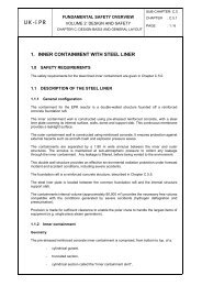
1.3.3.2. Penetrations<br />
Potential leakage paths through the penetrations are shown in Figure A.<br />
external leak<br />
Valve seat leakage<br />
FIGURE A: IDENTIFICATION OF POTENTIAL LEAKAGE PATHS THROUGH A<br />
PENETRATION
PRE-CONSTRUCTION SAFETY REPORT<br />
CHAPTER 6: CONTAINMENT AND SAFEGUARD<br />
SYSTEMS<br />
SUB-CHAPTER: 6.2<br />
PAGE : 8 / 124<br />
Document ID.No.<br />
<strong>UK</strong><strong>EPR</strong>-0002-062 Issue 03<br />
There is no leakage from the annulus into the environment through the external containment<br />
because the annulus is maintained at a negative pressure.<br />
In general, two isolation valves are provided for penetrations containing fluids (section 3 of this<br />
sub-chapter). Failure of the first (internal) isolation valve could potentially result in two leakage<br />
paths via the second (external) isolation valve: a leakage via the stuffing box, if the valve has<br />
one (an "external" valve leak), and a leakage via the valve seat (an "internal" leak).<br />
Potential leaks through penetrations communicating with the peripheral buildings<br />
There are penetrations where the internal valve is directly open to the containment atmosphere<br />
(e.g. hatches, heating ventilation and air conditioning (HVAC) penetrations, transfer tube). For<br />
these penetrations, if a potential leak via the internal valve is judged to have a potentially<br />
significant radiological impact, the external valve is equipped with a device that collects any<br />
potential leak from the gland and routes it to the annulus where it is filtered before being<br />
released via the stack. The corresponding leakage path is shown as path 1 in Figure B.<br />
For similar penetrations that have zero or limited radiological impact, containment by the pipe<br />
connected to the penetration external valve is considered sufficient to prevent a significant<br />
radiological release into the peripheral buildings (in most cases the pipe will be full of water).<br />
In all cases, and whether or not a device is installed to collect a leakage from the external<br />
isolation valve, the peripheral buildings provide an additional containment barrier.<br />
Potential leaks via the equipment hatch and air locks<br />
The equipment hatch and air locks that provide access for equipment and staff have a leak<br />
prevention system for collecting possible leaks (section 5 of this sub-chapter).<br />
Penetrations that do not communicate with peripheral buildings<br />
The only penetrations in this category are the main steam line and main feed line penetrations.<br />
Provided the integrity of the SG tubes is maintained, the steam and feed penetrations do not<br />
perform a containment function. Under these circumstances, containment is provided by the<br />
secondary cooling system boundary. In the event of SGTR, the isolation valves in the secondary<br />
systems contribute to the long-term containment function.<br />
All reasonably practicable measures have been applied to avoid potential direct leakages into<br />
the environment.
PRE-CONSTRUCTION SAFETY REPORT<br />
CHAPTER 6: CONTAINMENT AND SAFEGUARD<br />
SYSTEMS<br />
SUB-CHAPTER: 6.2<br />
PAGE : 9 / 124<br />
Document ID.No.<br />
<strong>UK</strong><strong>EPR</strong>-0002-062 Issue 03<br />
FIGURE B: SCHEMATIC DIAGRAM OF POTENTIAL LEAKAGE PATHS FROM THE<br />
REACTOR BUILDING TO THE ENVIRONMENT<br />
1.3.3.3. RIS [SIS] and EVU [CHRS]<br />
In certain accidents, the RIS [SIS] and EVU [CHRS] systems transport contaminated water<br />
outside the containment. This is discussed below.<br />
1.3.3.4. Foundation raft<br />
All reasonably practicable measures have been taken to exclude potential direct leaks into the<br />
environment via the foundation raft. In the event of accidents, specific measures are provided to<br />
ensure leak-tightness with respect to potential liquid leaks. Most of the lower part of the reactor<br />
building is occupied by the IRWST, which has a leak-tight liner, and the corium spreading area,<br />
which is also leak-tight. The leak-tight steel liner covering the internal walls of the inner<br />
containment extends to the interface between the foundation raft and the internal structure of the<br />
reactor building. Also, the presence of water on the foundation raft forms a barrier, preventing<br />
radionuclides from being transferred into the environment. The spreading area that collects the<br />
corium in the event of core melt accident leading to vessel rupture comprises specific layers for<br />
corium stabilisation. A corium cooling system beneath the spreading area protects the reactor<br />
building foundation raft from high temperatures.<br />
These provisions enable foundation raft integrity to be maintained (i.e. significant cracking is<br />
prevented) even in the event of a severe accident (section 6 of this sub-chapter).<br />
1.3.3.5. Conclusion<br />
The containment is designed to prevent direct leakage from the containment to the environment<br />
throughout the life of the plant. Any leakage that does occur is collected and filtered before<br />
release to the environment. Hence the probability of direct release into the environment is<br />
insignificant.
PRE-CONSTRUCTION SAFETY REPORT<br />
CHAPTER 6: CONTAINMENT AND SAFEGUARD<br />
SYSTEMS<br />
SUB-CHAPTER: 6.2<br />
PAGE : 10 / 124<br />
Document ID.No.<br />
<strong>UK</strong><strong>EPR</strong>-0002-062 Issue 03<br />
1.4. CONTAINMENT FUNCTION OF THE PERIPHERAL BUILDINGS AND<br />
THE EFFLUENT TREATMENT BUILDING<br />
1.4.1. Interface with the reactor building following activity release inside the<br />
reactor building<br />
1.4.1.1. Circulation of contaminated water outside the containment<br />
During certain accidents (e.g. severe accidents) the RIS [SIS] and EVU [CHRS] transport<br />
contaminated water outside the containment. Therefore, specific measures are provided for<br />
these systems to maintain the containment function.<br />
1.4.1.1.1. Specific measures with regard to leakages<br />
Specific measures are applied to parts of the systems that are likely to be potential sources of<br />
leakage outside the containment e.g.:<br />
• The functional characteristics of the EVU [CHRS] cooling system are such that leaks<br />
from heat exchangers are precluded (section 7 of this sub-chapter).<br />
• Specific leak detection provisions are made to isolate each RIS [SIS] and EVU<br />
[CHRS] train if a leak is detected (section 7 of this sub-chapter for the EVU [CHRS]<br />
and Sub-chapter 6.3 for the RIS [SIS]).<br />
• A specific isolation device is fitted to the pipes between the IRWST and the RIS [SIS]<br />
and EVU [CHRS] pumps. The pipework between the IRWST and the isolation valves<br />
outside the containment is contained in a leak-tight protective sheath (section 7of this<br />
sub-chapter for the EVU [CHRS] and Sub-chapter 6.3 for the RIS [SIS]).<br />
The sections of these systems outside the reactor building are located in specific rooms in the<br />
peripheral buildings. If one of the systems fails, the containment function is provided by<br />
peripheral buildings.<br />
1.4.1.1.2. Long-term reparability<br />
To ensure containment of the radioactive substances over the long term, it is possible to repair:<br />
• the RIS [SIS] providing core cooling<br />
• the EVU [CHRS] providing the containment heat removal in the event of a severe<br />
accident.<br />
Despite the presence of highly contaminated water, (when the EVU [CHRS] is operating) or<br />
moderately contaminated water (when the RIS [SIS] is operating), it is possible to repair the<br />
pumps after isolating the main system by closing the corresponding suction valve in the IRWST<br />
and draining and rinsing the connected pipework sections. Similarly, access to the dedicated<br />
EVU [CHRS] intermediate cooling system is possible without risk of contamination by<br />
pressurising the system and closing the power-operated valve.<br />
A preliminary list of requirements for accessibility to repair the systems used to maintain the final<br />
state in the long term is provided in Sub-chapter 12.5.
PRE-CONSTRUCTION SAFETY REPORT<br />
CHAPTER 6: CONTAINMENT AND SAFEGUARD<br />
SYSTEMS<br />
SUB-CHAPTER: 6.2<br />
1.4.1.1.3. Re-injection of contaminated effluents into the reactor building after an<br />
accident<br />
PAGE : 11 / 124<br />
Document ID.No.<br />
<strong>UK</strong><strong>EPR</strong>-0002-062 Issue 03<br />
<strong>Systems</strong> are provided to enable highly contaminated effluents to be re-injected into the reactor<br />
building following an RIS [SIS] leak in a safeguard building post LOCA.<br />
In addition, although an EVU [CHRS] leak is not expected to occur after a severe accident,<br />
means are provided to re-inject contaminated effluent back into the reactor building.<br />
The effluent re-injection function into the reactor building is provided by the RPE [NVDS] system<br />
during PCC and RRC-A events (Sub-chapter 11.4).<br />
For long term maintenance of the EVU [CHRS] system following a severe accident, the contents<br />
of the circuits are pumped back into the reactor building using the EVU [CHRS] circuits, and the<br />
circuits are then rinsed.<br />
1.4.1.2. Leaks through containment penetrations<br />
Most leakage is collected in the annulus, which is kept at sub-atmospheric pressure by the<br />
annulus ventilation system (EDE [AVS]). This system is also used to route any leakage through<br />
HEPA and iodine filters in series to the stack, from which they are released to the environment<br />
in a controlled manner.<br />
Leakages which are not collected in the annulus enter the peripheral buildings and are filtered<br />
before being released to the environment.<br />
Thus the peripheral buildings (safeguard buildings, nuclear auxiliary building and fuel building)<br />
contribute to the containment function.<br />
A static global leak-tightness criterion for each peripheral building (safeguard buildings, nuclear<br />
auxiliary building and fuel building) is defined at 0.3% vol/day (see Sub-chapter 3.3). Provisions<br />
implemented to ensure that this criterion is met, are as follows:<br />
• Semi-leak-tight doors are installed on the boundary of the controlled area (opening to<br />
the outside or located between the controlled and non-controlled areas). These semileak-tight<br />
doors are equipped with leak-tight seals on three sides and a friction brush<br />
at the floor.<br />
• Placing dampers on the air supply side in the nuclear auxiliary building.<br />
These provisions give significant margins and therefore a visual inspection of the equipment is<br />
sufficient to maintaining its efficiency.<br />
1.4.2. LHSI rooms in safeguard buildings 1 and 4<br />
In the event of a postulated RIS/RRA [SIS/RHRS] break in safeguard building divisions 1 and 4<br />
then, because the primary circuit temperature could exceed 100°C (only these two trains are<br />
operable above 100°C), the corresponding rooms (e.g. LHSI pump and heat exchanger rooms)<br />
could become pressurised. This could lead to the loss leak-tightness and release of radioactive<br />
material into the atmosphere without the possibility of containment within the rooms in the longterm.<br />
To avoid this, dedicated devices are provided:
PRE-CONSTRUCTION SAFETY REPORT<br />
CHAPTER 6: CONTAINMENT AND SAFEGUARD<br />
SYSTEMS<br />
SUB-CHAPTER: 6.2<br />
PAGE : 12 / 124<br />
Document ID.No.<br />
<strong>UK</strong><strong>EPR</strong>-0002-062 Issue 03<br />
• Protection of the LHSI pump and heat exchanger rooms in safeguard buildings 1 and<br />
4 is provided by reinforced doors which are designed to withstand a differential<br />
pressure of 120 mbar. See Sub-chapter 3.3 for a description of the safeguard<br />
buildings.<br />
• Limitation of the pressure increase using a dedicated device: In the event of a break,<br />
the released steam is routed to an opening in an area that is normally isolated. A<br />
device is provided that releases the pressure when the pressure difference exceeds<br />
50 mbar. This device is designed so that containment isolation can be restored after a<br />
period of time following the break isolation and to restore the dynamic containment<br />
using the ventilation systems.<br />
1.4.3. Fuel building<br />
The following measures are applied to ensure the containment function provided by the Fuel<br />
Building:<br />
• The ventilation systems provide dynamic containment following a fuel handling<br />
accident, regardless of whether it occurs in the fuel building or in the reactor building,<br />
when the equipment hatch is open (Sub-chapter 9.4).<br />
• The fuel building provides static containment in the event of the atmosphere<br />
becoming saturated as a result of high temperatures in the spent fuel pool following<br />
loss of the two main PTR [FPCS] trains.<br />
• The design ensures that melting of spent fuel is practically eliminated (Sub-chapter<br />
16.3) and the probability of spent fuel pool boiling is sufficiently low (Sub-chapter<br />
16.3) that the fuel building does not need to provide a containment function.<br />
1.4.4. Nuclear auxiliary building<br />
Because the nuclear auxiliary building ventilation system is not F1 classified, then post accident<br />
it is assumed that the air from the rooms is ventilated through a High Efficiency Particulate Air<br />
(HEPA) filter before being discharged into the stack. Aerosol retention in these filters is<br />
conservatively ignored. Nevertheless, the analysis of bounding accidents in the nuclear auxiliary<br />
building (i.e. rupture of a TEG [GWPS] or RCV [CVCS] line), shows that the resulting discharges<br />
are much lower than the allowable limits for each category of accident (Chapter 14).<br />
For the special case of an earthquake causing multiple pipe ruptures in the nuclear auxiliary<br />
building, containment of the radiological releases is provided statically by the isolation of the air<br />
inlet dampers and closure of the dampers in the extraction lines located at the building exhausts.<br />
The radiological consequences of an earthquake affecting the nuclear auxiliary building are<br />
presented in Sub-chapter 14.6 and are shown to meet the dose objectives even assuming the<br />
overall leak rate being an order of magnitude greater than assumed for non-seismic events (i.e.<br />
5% vol/day) taking into account the inventory of contaminated liquid and gas discharged into the<br />
building.
PRE-CONSTRUCTION SAFETY REPORT<br />
CHAPTER 6: CONTAINMENT AND SAFEGUARD<br />
SYSTEMS<br />
1.4.5. Effluent treatment building<br />
SUB-CHAPTER: 6.2<br />
PAGE : 13 / 124<br />
Document ID.No.<br />
<strong>UK</strong><strong>EPR</strong>-0002-062 Issue 03<br />
The containment function extends to the Effluent Treatment Building, which is equipped with an<br />
F2 classified Waste Building Treatment Ventilation system (Sub-chapter 9.4). In normal<br />
operation, extraction is via a HEPA filter. If activity is detected, extraction is automatically<br />
switched to the iodine traps. If the ventilation system is unavailable, static containment is<br />
applied.<br />
1.5. DEFINITION AND ANALYSIS OF THE CONTAINMENT LOAD<br />
COMBINATIONS<br />
1.5.1. Definition of the containment load combinations<br />
The load combinations considered for containment design are derived from accident sequences<br />
taken into account during the design process.<br />
<strong>Containment</strong> load combinations are calculated for the following conditions:<br />
• LB LOCA Loss of Coolant Accident - Large Break<br />
• 2A-LOCA Loss of Coolant Accident - Guillotine Break<br />
• SLB Steam Pipe Rupture<br />
• 2A-SLB Steam Pipe Rupture - Guillotine Break<br />
• Severe accident<br />
Pressure and temperature calculations associated with the first four cases are presented in this<br />
section. The calculation of pressures and temperatures associated with severe accidents is<br />
presented in Sub-chapter 16.2.<br />
As discussed in this section, (P, T) decoupling curves have been used for the containment<br />
design. The combination of loads considered for the containment design (steel liner and<br />
concrete internal containment) is presented in Sub-chapter 3.4.<br />
1.5.2. Definition of Mass and Energy Release in Incidents and Accidents as<br />
Design Basis for <strong>Containment</strong><br />
The consequences of the Mass and Energy Release (MER) on the behaviour of the containment<br />
wall are examined for the PCC Large Break Loss of Coolant Accident, 2A-LOCA, PCC Steam<br />
Line Break, 2A-SLB, and severe accidents.<br />
1.5.2.1. Large break LOCA (PCC)<br />
1.5.2.1.1. Introduction<br />
This section summarises results with respect to mass and energy release (MER) into<br />
containment in the event of a complete rupture of the pressuriser surge line (largest LOCA break<br />
size in PCC).
1.5.2.1.2. Calculation model<br />
PRE-CONSTRUCTION SAFETY REPORT<br />
CHAPTER 6: CONTAINMENT AND SAFEGUARD<br />
SYSTEMS<br />
SUB-CHAPTER: 6.2<br />
PAGE : 14 / 124<br />
Document ID.No.<br />
<strong>UK</strong><strong>EPR</strong>-0002-062 Issue 03<br />
The calculation is performed using the CATHARE SB LOCA/IB LOCA methodology. The input<br />
model uses the same nodalisation as used in the Chapter 14 PCC studies: the evolution of the<br />
accident is also described there. The containment code CONPATE 4 is coupled with CATHARE<br />
to achieve a more precise result with respect to the MER. In this way, both the RCP [RCS]<br />
response and the containment response are calculated simultaneously. The CONPATE 4<br />
results (containment backpressure and MHSI / LHSI temperature) are used as a boundary<br />
condition for CATHARE.<br />
The CATHARE and CONPATE 4 codes are described in Appendix 14A.<br />
1.5.2.1.3. Initial and boundary conditions<br />
CATHARE modelling of primary/secondary systems<br />
Conservative assumptions with regard to the MER are used. The most important are (see<br />
Sub-chapter 14.5, Section 14.5.6 – Table 1):<br />
• Maximum decay heat (ORIGEN/S results + uncertainties).<br />
• Maximum initial reactor power (102% nominal power).<br />
• Loss of off-site power with RT signal.<br />
• Loss of 1 diesel due to single failure (loss of 1 MHSI + 1 LHSI + 1 ASG [EFWS]).<br />
• Loss of 1 diesel due to preventive maintenance (loss of 1 MHSI + 1 LHSI + ASG<br />
[EFWS]).<br />
• Protection and safeguard actions limited to F1 systems.<br />
• Uncertainties assumed for F1 I&C functions credited (as in PCC-4 core calculations,<br />
Sub-chapter 14.5).<br />
• Minimum effectiveness of F1 fluid systems assumed (as in PCC-4 core calculations,<br />
Sub-chapter 14.5).<br />
• No manual actions credited.<br />
CONPATE 4 modelling of the containment<br />
Conservative assumptions are used for maximum containment pressure and maximum IRWST<br />
temperature. Specifically the containment volume, IRWST volume, and the heat transfer<br />
coefficient of atmosphere/water are minimised.<br />
1.5.2.1.4. Analysis results<br />
The thermal hydraulic behaviour of the RCP [RCS] is described in the section covering the PCC<br />
Large Break LOCA (Sub-chapter 14.5).<br />
The MER related to the LB LOCA "rupture of the PZR surge line" have not been updated for the<br />
<strong>UK</strong> <strong>EPR</strong> PCSR. Instead the MER calculated in the BDR-99 analysis are used to assess the<br />
containment pressure and temperature behaviour.
PRE-CONSTRUCTION SAFETY REPORT<br />
CHAPTER 6: CONTAINMENT AND SAFEGUARD<br />
SYSTEMS<br />
SUB-CHAPTER: 6.2<br />
PAGE : 15 / 124<br />
Document ID.No.<br />
<strong>UK</strong><strong>EPR</strong>-0002-062 Issue 03<br />
The MER related to the <strong>EPR</strong>4500 characteristics given in the PCSR, are bounded by the MER<br />
calculated for the <strong>EPR</strong>4900 characteristics given in the BDR-99 (PCSR Appendix 6, section<br />
6.2.1.5.2.1) as the:<br />
• Core power level is lower (-8% in the <strong>EPR</strong>4500).<br />
• Initial RCP [RCS] water inventory and temperature are similar.<br />
• Initial SG water inventory is smaller (-8% in the <strong>EPR</strong>4500), initial SG water temperature<br />
is slightly higher, resulting in a lower initial SG energy.<br />
• RIS [SIS] injection flow rate is identical at low pressure level, is slightly increased at<br />
high pressure level (MHSI with higher delivery pressure, accumulators and LHSI<br />
unchanged, in the <strong>EPR</strong>4500).<br />
• IRWST initial water content and temperature are unchanged, providing a larger heat<br />
sink reserve in the <strong>EPR</strong>4500 with respect to the core power level.<br />
Immediately after the break, during the RCP [RCS] depressurisation/blowdown phase, the MER<br />
of the <strong>EPR</strong>4500 is similar to that of the <strong>EPR</strong>4900 (as they have similar initial mass and energy<br />
content).<br />
In the long term when the RCP [RCS] pressure is close to the containment pressure, after the<br />
end of RCP [RCS] blowdown, the MER of the <strong>EPR</strong>4500 are less limiting for the containment<br />
pressure and temperature behaviour than the MER of the <strong>EPR</strong>4900 (lower core power, larger<br />
LHSI heat removal capacity, larger IRWST heat sink).<br />
1.5.2.2. 2A-LOCA<br />
1.5.2.2.1. Introduction<br />
This section summarises results with respect to the MER into containment in the event of a<br />
double-ended (2A) guillotine break of a main coolant line cold leg. This break is considered<br />
despite the RCP [RCS] break preclusion concept as a defence-in-depth measure to check the<br />
capability of the containment to withstand the largest RCP [RCS] pipe break under realistic<br />
conditions.<br />
1.5.2.2.2. Calculation model<br />
The analysis is performed using the CATHARE computer code. <strong>Containment</strong> pressure is<br />
provided by the computer code CONPATE 4, which runs interactively with CATHARE. In this<br />
way, both the RCP [RCS] response and the containment response are calculated<br />
simultaneously.<br />
CATHARE and CONPATE 4 codes are described in Appendix 14A.<br />
1.5.2.2.3. Initial and boundary conditions<br />
CATHARE modelling of primary/secondary systems<br />
Best-estimate assumptions are used; the most important are [Ref]:<br />
• Initial rated reactor power 100%.
PRE-CONSTRUCTION SAFETY REPORT<br />
CHAPTER 6: CONTAINMENT AND SAFEGUARD<br />
SYSTEMS<br />
• Decay heat corresponding to ORIGEN/S results (without uncertainties).<br />
SUB-CHAPTER: 6.2<br />
PAGE : 16 / 124<br />
Document ID.No.<br />
<strong>UK</strong><strong>EPR</strong>-0002-062 Issue 03<br />
• All trains of safety injection system available (no single failure, no preventive<br />
maintenance).<br />
• Off-site power available.<br />
CONPATE 4 modelling of the containment<br />
In general, best-estimate initial and boundary conditions are used [Ref], i.e. containment volume<br />
and heat transfer areas in containment correspond to nominal values. Assumptions, which<br />
maximise the MER are made for those parameters which do not have a clear best-estimate<br />
value: e.g. heat transfer coefficient between atmosphere and IRWST, LHSI heat exchanger<br />
characteristics.<br />
1.5.2.2.4. Analysis results<br />
The MER related to the 2A cold leg break have not been updated for the <strong>UK</strong> <strong>EPR</strong> PCSR.<br />
Instead the MER calculated in the BDR-99 analysis are used to assess the containment<br />
pressure and temperature behaviour.<br />
The MER related to the <strong>EPR</strong>4500 characteristics given in the PCSR, are bounded by the MER<br />
calculated for the <strong>EPR</strong>4900 characteristics given in the BDR-99 (PCSR Appendix 6, section<br />
6.2.1.5.2.2): for the same reasons as given for the PCC LB LOCA above.<br />
1.5.2.3. Steam line break (PCC)<br />
1.5.2.3.1. Introduction<br />
Application of the break preclusion concept for the main steam lines (MSL) inside the<br />
containment building, means that the PCC steam line break (SLB) is limited to rupture of a pipe<br />
connected to the MSL (sensor or venting line). The associated break size is far below the MSL<br />
cross section and the SG-outlet flow limiter area. The resulting MER are, therefore, much lower<br />
than the MER which could result from the rupture of the MSL.<br />
In accordance with the approach used in the PCSR for the PCC SLB-analyses related to the<br />
core behaviour (Sub-chapter 14.5), the PCC SLB assumed in the PCSR for the containment<br />
behaviour is the double-ended guillotine break of a MSL located at SG outlet. This conservative<br />
approach does not take account of the break preclusion concept for the MSL design inside the<br />
containment, which excludes the rupture of the MSL as a PCC accident (and as a RRC-A one).<br />
This conservative approach is used to simplify the calculation:<br />
• Consideration of the MSLB accident bounds all of the "MSL-connected pipe break"<br />
PCC events and the "feed line break" PCC event.<br />
• The BDR-99 PCC calculation of the 2A SLB, performed without claiming the break<br />
preclusion concept (not implemented in the <strong>EPR</strong>4900 design covered by the BDR-99),<br />
is used directly to determine a bounding MER for the <strong>EPR</strong>4500 design covered by the<br />
PCSR, without the need for a specific <strong>EPR</strong>4500 calculation.
PRE-CONSTRUCTION SAFETY REPORT<br />
CHAPTER 6: CONTAINMENT AND SAFEGUARD<br />
SYSTEMS<br />
SUB-CHAPTER: 6.2<br />
PAGE : 17 / 124<br />
Document ID.No.<br />
<strong>UK</strong><strong>EPR</strong>-0002-062 Issue 03<br />
As a result, for the PCSR, the double-ended guillotine break of a main steam line inside the<br />
containment building is selected as the bounding break case for the containment loads for all<br />
PCC events affecting the secondary system. The general description of the accident is given in<br />
the section covering the PCC SLB (see Sub-chapter 14.5).<br />
An MSLB leads to a MER that depends on initial and boundary conditions, and on the single<br />
failure postulated for the safety grade systems. Sensitivity studies are then performed to find the<br />
most onerous case:<br />
• Sensitivity to the fuel management (UO2, MOX).<br />
• Sensitivity to the initial level of power (from 0% to 102% of full power).<br />
• Sensitivity to one of the following single failures:<br />
o Failure to drop the highest worth RCCA; stuck in its fully withdrawn position.<br />
o Failure to close a main feed water isolation valve on the affected SG.<br />
o Failure to close the main steam isolation valve (VIV [MSIV]) on the affected<br />
SG.<br />
1.5.2.3.2. Calculation model<br />
The computer code used is THEMIS (Appendix 14A). This code calculates the MER through the<br />
break from the affected SG, and from the three non-affected SG through the main steam<br />
header, up to time of VIV [MSIV] closure. In the event of a failure to close the VIV [MSIV] on the<br />
affected SG, the blowdown of the main steam header is taken into account.<br />
The analysis methodology for the core behaviour calculation is described in the PCC SLB<br />
section (Sub-chapter 14.5), except that the core neutronics is directly calculated using a<br />
conservative "point kinetics model". Actually, only the total core power is of interest for the MER<br />
calculations. In this methodology, calculation assumptions are adapted to ensure conservative<br />
MER results, as indicated below.<br />
1.5.2.3.3. Initial and boundary conditions<br />
a) General assumptions (see Sub-chapter 14.5, section 2)<br />
These assumptions correspond to a conservative methodology for the calculation of the MER for<br />
a SLB, aimed at maximising the MER results:<br />
• Maximisation of the initial energy in the primary side:<br />
Uncertainties are applied as follows:<br />
o + 2% on core power.<br />
o + 2.5 bar on pressuriser pressure.<br />
o + 2.5°C on average primary temperature.<br />
Sensitive heat from primary metal structures and power from the primary pumps are taken into<br />
account.
PRE-CONSTRUCTION SAFETY REPORT<br />
CHAPTER 6: CONTAINMENT AND SAFEGUARD<br />
SYSTEMS<br />
SUB-CHAPTER: 6.2<br />
PAGE : 18 / 124<br />
Document ID.No.<br />
<strong>UK</strong><strong>EPR</strong>-0002-062 Issue 03<br />
• Maximisation of the heat transferred from the primary circuit to the secondary circuit:<br />
o The SG tubes are clean and none are plugged.<br />
o The mechanical primary flow rate is considered.<br />
o The RCP [RCS] pumps are kept in operation.<br />
o Conservative neutronics data is used with respect to the core return to power.<br />
o The maximum decay heat curve is used.<br />
• Maximisation of the mass and energy release from the secondary side:<br />
o +10% uncertainty is applied to the initial SG water inventory, which includes<br />
uncertainties in the SG level control and in the SG water temperature.<br />
o The ARE [MFWS] temperature is maximised: nominal + 5°C.<br />
o The flashing effect 1<br />
in the main feedwater line is taken into account.<br />
o A constant back pressure of 1 bar is assumed in the containment atmosphere.<br />
o Perfect moisture separation is assumed at the steam generator outlet, leading<br />
to a break flow quality of 1 (pure steam flow at the break maximises the total<br />
energy released).<br />
o Blowdown of the main steam header is taken into account until VIV [MSIV]<br />
closure is achieved.<br />
b) Specific assumptions (see Sub-chapter 14.5, section 2)<br />
The I&C protection signals are described in the SLB section (see Sub-chapter 14.5). The<br />
effective protection actions are taken into account as follows, (with maximum occurrence times<br />
considered conservatively):<br />
• Reactor trip (for SLB at power):<br />
o Performed by RCCA drop, F1A qualified.<br />
o On F1A signal “SG pressure drop > MAX 1", with 0.9 seconds signal delay,<br />
0.3 seconds RCCA gripper release, and 5 seconds RCCA dropping time.<br />
• MS isolation:<br />
o Performed by closing the four VIV [MSIV], F1A qualified.<br />
o On F1A signal “SG pressure drop > MAX 1", with 0.9 seconds signal delay<br />
and 5 seconds VIV [MSIV] closing time (step wise).<br />
1 After Main Feed Water isolation, a volume of water remains in the ARE [MFWS] pipes at the initial ARE [MFWS]<br />
temperature and SG pressure. As the SG pressure decreases below the saturation pressure of the ARE [MFWS],<br />
this water flashes to steam in the ARE [MFWS] pipes and flows into the affected SG.
SG<br />
PRE-CONSTRUCTION SAFETY REPORT<br />
CHAPTER 6: CONTAINMENT AND SAFEGUARD<br />
SYSTEMS<br />
• ARE [MFWS] isolation:<br />
SUB-CHAPTER: 6.2<br />
PAGE : 19 / 124<br />
Document ID.No.<br />
<strong>UK</strong><strong>EPR</strong>-0002-062 Issue 03<br />
o Performed by closing the three ARE [MFWS] isolation valves 2<br />
on each SG, all<br />
F1A qualified:<br />
- the high load isolation valve (MFIV-HL) closes the high load line,<br />
- the low load isolation valve (MFIV-LL) closes the low load line,<br />
- the main isolation valve (MFIV) closes the main FW line.<br />
o The MFIV-HL is closed on F1A signal “SG pressure drop > MAX 1", with<br />
0.9 seconds signal delay and 15 seconds valve closing time (step wise),<br />
o The MFIV-LL and the MFIV are closed on F1A signal “SG pressure drop ><br />
MAX 2", with 0.9 seconds signal delay and 15 seconds valve closing time<br />
(step wise).<br />
MFIV<br />
ARE [MFWS] MAIN LINE<br />
Figure C: ARE [MFWS] isolation valves<br />
The ARE [MFWS], AAD [SSS] and ASG [EFWS] flows entering the affected SG prior to their<br />
isolation are bounding values:<br />
ARE [MFWS] flow rate 3<br />
ARE [MFWS] HIGH-LOAD LINE<br />
MFIV-HL<br />
MFIV-LL<br />
ARE [MFWS] LOW-LOAD LINE<br />
ARE [MFWS] - HEADER<br />
For an initial power state higher than 20% Nominal Power (NP), the ARE [MFWS] flow rate<br />
entering the affected SG is:<br />
o ~160% of nominal ARE [MFWS] flow before main steam header isolation.<br />
o ~240% of nominal ARE [MFWS] flow after main steam header isolation, and<br />
before ARE [MFWS] high-load line isolation.<br />
o ~130% of nominal ARE [MFWS] flow after main steam header isolation, and<br />
ARE [MFWS] high-load line isolation, 0 kg/s after ARE [MFWS] main line and<br />
low-load line isolation.<br />
2 This ARE [MFWS] isolation valve configuration is claimed independently of the <strong>EPR</strong> final configuration. With<br />
respect to MER, this is the most limiting case because only one isolation valve closes on the occurrence of the first<br />
isolation signal (MAX 1), which results in the non-isolation of the high-load line until the occurrence of the second<br />
isolation signal (MAX 2) in the event of a single failure when the high-load isolation valve attempts to close.<br />
3 Following a more precise definition of the Conventional Island, these values will be redefined
PRE-CONSTRUCTION SAFETY REPORT<br />
CHAPTER 6: CONTAINMENT AND SAFEGUARD<br />
SYSTEMS<br />
SUB-CHAPTER: 6.2<br />
PAGE : 20 / 124<br />
Document ID.No.<br />
<strong>UK</strong><strong>EPR</strong>-0002-062 Issue 03<br />
For an initial power state lower than 20% NP, the high-load line is closed in normal operation,<br />
and the ARE [MFWS] flow rate entering the affected SG is:<br />
o ~130% of nominal ARE [MFWS] flow before ARE [MFWS] main line and lowload<br />
line isolations, 0 kg/s after ARE [MFWS] main line and low-load line<br />
isolation<br />
AAD [SSS] flow rate: The start-up system is not considered in this study because the ARE<br />
[MFWS] system remains in operation until total ARE [MFWS] isolation. The ARE [MFWS] flow<br />
rate bounds the AAD [SSS] flow rate.<br />
ASG [EFWS] flow rate: The emergency feed water flow rate into the affected SG is taken at the<br />
constant value of 200 m 3 /h, with a maximum temperature of 50°C, from the onset of the<br />
accident. This is cancelled by the operator 0.5 hours after reactor trip. The value of 200 m 3 /h<br />
does not currently take credit for the ASG [EFWS] flow active limitation; this is excessively<br />
conservative since this failure is assumed to be coincident with the already assumed single<br />
failure.<br />
Note:<br />
The design of the ARE [MFWS] system, given in Figure C above, has changed since the<br />
Basic Design. The modifications are as follows:<br />
• The current ARE [MFWS] design is presented in Sub-chapter 10.6; there is<br />
redundancy on the isolation valves (MFIVs). This prevents any failure of isolation of<br />
the main feedwater system.<br />
• The MFIV closure time is longer on the current <strong>EPR</strong> studies.<br />
Considering the BDR-99 analysis was carried out at 4900 MW, with a larger volume of water in<br />
the steam generator and a failure of the ARE [MFWS] MFIV, the study presented in the PCSR is<br />
the most conservative case, both in terms of mass and energy released and meeting the safety<br />
criteria.<br />
c) Single Failure<br />
Sensitivity to the following single failures is performed, in order to identify the most limiting:<br />
• Single failure to close of the MFIV-HL valve of the affected SG:<br />
As a consequence, the isolation of the ARE [MFWS] high-load line fails. The ARE [MFWS] flow<br />
entering the affected SG remains at ~240% NF (instead of ~130% NF) until the isolation of the<br />
ARE [MFWS] main line and ARE [MFWS] low-load line is achieved.<br />
• Single failure of the highest worth RCCA:<br />
The reactivity is calculated considering all RCCA inserted in the core except the highest worth<br />
RCCA, which is assumed to be stuck in its fully withdrawn position.<br />
• Single failure to close of the VIV [MSIV] of the affected SG:<br />
The VIV [MSIV] of the affected SG remains open. Consequently, the steam contained in the<br />
main steam header flows into the containment. The main steam header includes the main steam<br />
lines up to the main steam bypass and the turbine inlet pipes up to the turbine stop valves. The<br />
total main steam header volume is assumed to be 300 m 3 [Ref].
d) Preventative maintenance<br />
PRE-CONSTRUCTION SAFETY REPORT<br />
CHAPTER 6: CONTAINMENT AND SAFEGUARD<br />
SYSTEMS<br />
SUB-CHAPTER: 6.2<br />
PAGE : 21 / 124<br />
Document ID.No.<br />
<strong>UK</strong><strong>EPR</strong>-0002-062 Issue 03<br />
Preventative maintenance has no consequence for the MER analysis in the event of a SLB, as<br />
the protective actions are limited to reactor trip and valve actuations, (isolation functions) which<br />
are not impacted by the preventative maintenance.<br />
e) Break assumption�<br />
The break area on the SG side corresponds to the flow area of the SG flow-limiter located at the<br />
SG outlet, i.e. 1,300 cm². The break area on the opposite side corresponds to the flow area of<br />
the fully open VIV [MSIV], i.e. 3,200 cm² (this kind of valve presents an area corresponding to a<br />
diameter between 19” and 23”. However, a bounded section value is taken into account with<br />
regard to pressure and temperature in the containment. It corresponds to a diameter of 25”, i.e.<br />
an area of 3,200 cm²).<br />
1.5.2.3.4. Analysis results<br />
Sensitivity studies have shown that the most limiting configuration corresponds to the following<br />
conditions:<br />
• 0% for initial power (+2% considered, including decay heat at hot shutdown).<br />
• Failure to close the VIV [MSIV] on the affected SG.<br />
The MER for the 2A SLB under PCC analysis conditions have not been updated for the <strong>UK</strong> <strong>EPR</strong><br />
PCSR. Instead the MER calculated in the BDR-99 analysis are used to assess the containment<br />
pressure and temperature behaviour.<br />
The MER related to the <strong>EPR</strong>4500 characteristics given in the PCSR, are bounded by the MER<br />
calculated for the <strong>EPR</strong>4900 characteristics given in the BDR-99 (PCSR Appendix 6, section<br />
6.2.1.5.2.3):<br />
1.5.2.4. 2A-SLB<br />
• Initial SG water mass is smaller (-8% in the <strong>EPR</strong>4500), initial SG water temperature is<br />
slightly higher (+3°C in the <strong>EPR</strong>4500), resulting in a lower initial SG energy (-8% in the<br />
<strong>EPR</strong>4500). This is the major contributor to the containment overpressure and overtemperature<br />
peaks.<br />
• The longer closing time of the ARE [MFWS] isolation valves in the <strong>EPR</strong>4500<br />
(15 seconds instead of 10 seconds), leads to 3 te more water being injected into the<br />
affected SG. However this does not change the assessment.<br />
• Other parameters are similar or less onerous: initial RCP [RCS] water inventory and<br />
temperature are similar, ARE [MFWS] flow rate is lower (due to lower core power<br />
level), ASG [EFWS] flow rate is lower, core return to power is expected to be similar<br />
or lower (higher shutdown margin credited, similar neutronics coefficients).<br />
Even though the break preclusion concept is applied to the MSL inside the containment, its<br />
failure is considered as a defence-in-depth measure to check the capability of the containment<br />
to withstand the largest MSS pipe break under realistic conditions. In the PCSR, this 2A-SLB<br />
case under realistic conditions is bounded by the 2A-SLB case treated under PCC conditions<br />
above (conservative case retained for PCC SLB).
1.5.2.5. Severe accidents<br />
PRE-CONSTRUCTION SAFETY REPORT<br />
CHAPTER 6: CONTAINMENT AND SAFEGUARD<br />
SYSTEMS<br />
SUB-CHAPTER: 6.2<br />
PAGE : 22 / 124<br />
Document ID.No.<br />
<strong>UK</strong><strong>EPR</strong>-0002-062 Issue 03<br />
The containment pressures and temperatures were calculated assuming total core rupture<br />
following a large LOCA based on a new reference model of the containment called the "Basic<br />
<strong>Containment</strong> Model".[Ref]<br />
1.5.3. List of Inputs for P and T Calculations under LB LOCA, 2A-LOCA, SLB and<br />
2A-SLB Conditions<br />
P and T calculation code<br />
The PAREO 9 computer code has been used. It uses the same physical models as PAREO 8<br />
code which is described in Appendix 16A.<br />
<strong>Containment</strong> data [Ref]<br />
The free volume of the containment is 80,235 m 3 . The volume of water in the IRWST is<br />
assumed to be 1,920 m 3 for the maximum containment pressure calculation.<br />
The following material properties have been assumed:<br />
Material Specific Mass<br />
(kg/m 3 Thermal Conductivity<br />
)<br />
(W/m o Specific Heat<br />
C)<br />
(J/kg o C)<br />
Steel 7,770 45 502<br />
Concrete 2,306 1.73 880<br />
The steel properties are usually taken into account.<br />
The concrete properties are taken into account for conservative studies.<br />
The following characteristics are assumed for the steel liner:<br />
• Coating thickness: 0.4 mm<br />
• Steel liner thickness: 7.4 mm<br />
• Generalised gap (air): 3 mm (this assumption is strongly conservative).<br />
The impact of the steel liner on containment pressure and temperature calculations has only<br />
been analysed for the most limiting case, i.e. the steam line break.<br />
Initial conditions<br />
Uniform initial conditions have been assumed:<br />
• Wall structures, atmosphere and IRWST temperature, T = 42°C.<br />
• <strong>Containment</strong> pressure, Pgaz = 1.1 bar (conservative value).<br />
Other constant conditions have been assumed:<br />
• Outside temperature: Toutside = 30°C.<br />
• Ground temperature: Tground = 20°C.
Heat transfer coefficient<br />
PRE-CONSTRUCTION SAFETY REPORT<br />
CHAPTER 6: CONTAINMENT AND SAFEGUARD<br />
SYSTEMS<br />
SUB-CHAPTER: 6.2<br />
PAGE : 23 / 124<br />
Document ID.No.<br />
<strong>UK</strong><strong>EPR</strong>-0002-062 Issue 03<br />
A conservative heat transfer coefficient has been used between the containment atmosphere<br />
and the structures. This is normal for LOCA calculations.<br />
1.5.4. Results of Analyses<br />
1.5.4.1. P and T in the event of LB LOCA<br />
The event analysed is the total rupture of the pressuriser surge line at its connection to the hot<br />
leg. This scenario, which is used as part of the containment design, is a PCC-4 LOCA.<br />
Pressure and temperature results<br />
Pressure and temperature in the containment are presented in Appendix 6 (BDR 99 extract -<br />
6.2.1.5.4 - Figures 1 and 2) with:<br />
• Pgaz: total containment pressure.<br />
• Pvap: partial pressure of steam.<br />
• Tliq: IRWST temperature.<br />
• Tgaz: atmosphere temperature.<br />
• TsatPvap: saturation temperature for the partial pressure of steam.<br />
The maximum pressures and temperatures are 4.5 bar and 177°C, occurring at 150 seconds.<br />
1.5.4.2. P and T in the case of 2A-LOCA<br />
The event analysed is the guillotine break of a primary cooling system cold leg. This bounding<br />
accident is neither a PCC-4 nor a RRC-A sequence; it is a specific study which is taken into<br />
account in the containment design.<br />
The MER were calculated in accordance with the 2A LOCA guidelines with realistic<br />
assumptions. The pressure and temperature calculations are performed with conservative<br />
assumptions defined below.<br />
Pressure and temperature results<br />
Pressure and temperature in the containment are presented in Appendix 6 (BDR 99 extract -<br />
6.2.1.5.4 - Figures 3 and 4) with:<br />
• Pgaz: total containment pressure.<br />
• Pvap: partial pressure of steam.<br />
• Tliq: IRWST temperature.<br />
• Tgaz: atmosphere temperature.<br />
• TsatPvap: saturation temperature for the partial pressure of steam.
PRE-CONSTRUCTION SAFETY REPORT<br />
CHAPTER 6: CONTAINMENT AND SAFEGUARD<br />
SYSTEMS<br />
SUB-CHAPTER: 6.2<br />
PAGE : 24 / 124<br />
Document ID.No.<br />
<strong>UK</strong><strong>EPR</strong>-0002-062 Issue 03<br />
The maximum pressures and temperatures are 4.3 bar and 182°C, occurring at 20 seconds.<br />
1.5.4.3. P and T in the case of SLB<br />
The event analysed is the 2A break of the main steam line. This case bounds the SLB PCC-4<br />
accidents. The calculation relies on main feed water line isolation occurring at 16.1 seconds<br />
(signal + valve closure) after the steam line break [Ref].<br />
This accident is the most limiting one identified previously in the BDR and has been selected to<br />
evaluate the effects of the steel liner on containment pressure and temperature.<br />
Pressure and temperature results<br />
Pressure and temperature in the containment are presented in Section 6.2.1 - Figures 1 and 2<br />
(24 hour period) and in Section 6.2.1 - Figures 3 and 4 (2000 second period) with:<br />
• Pgaz: total containment pressure<br />
• Pvap: partial pressure of steam.<br />
• Tliq: IRWST temperature.<br />
• Tgaz: atmosphere temperature.<br />
• TsatPvap: saturation temperature for the partial pressure of steam.<br />
The P and T curves show two peaks. The maximum values obtained are:<br />
• 5.2 bar and 183°C, occurring at 324 seconds for the first peak corresponding to<br />
depressurisation of the affected SG.<br />
• 4.8 bar and 138.5°C, occurring at 1,800 seconds for the second peak, limited by<br />
isolation of the ASG [EFWS] of the affected SG.<br />
Compared with the results in the BDR, the impact of the steel liner is limited to the second peak<br />
which is 300 mbar and 3.5°C greater. This is due to the very conservatively assumed<br />
generalised gap which “insulates” the concrete from the liner.<br />
After 30 minutes, there is no further significant release into the containment and the energy<br />
present in the containment is removed by the structures. Pressure and temperature decrease to<br />
1.3 bar and 62.5°C 24 hours after the start of the accident.<br />
The impact of the steel liner on the P and T containment loads is very limited even assuming a<br />
total air gap between the steel liner and the concrete. This confirms that it is not necessary to reperform<br />
the calculations for all cases.<br />
The maximum temperature for containment walls is lower than the saturation temperature. This<br />
indicates that a film of condensed water will form on the containment walls, where the<br />
temperature does not exceed 140°C.
PRE-CONSTRUCTION SAFETY REPORT<br />
CHAPTER 6: CONTAINMENT AND SAFEGUARD<br />
SYSTEMS<br />
1.5.4.4. P and T in the event of 2A-SLB<br />
SUB-CHAPTER: 6.2<br />
PAGE : 25 / 124<br />
Document ID.No.<br />
<strong>UK</strong><strong>EPR</strong>-0002-062 Issue 03<br />
Even though the break preclusion concept is applied to the main steam line inside the<br />
containment, this event is considered in order to ensure the containment can withstand the<br />
largest main steam pipe break assuming realistic conditions, in accordance with the<br />
defence-in-depth methodology.<br />
The P and T loads in the containment calculated for a 2A-SLB with realistic modelling conditions<br />
are bounded by the PCC-4 2A-SLB P and T loads presented above.<br />
1.5.4.5. P and T in the event of a severe accident<br />
The severe accident sequences taken into account are:<br />
• LB LOCA: guillotine break of the surge line<br />
• SB LOCA: 50mm break in cold leg<br />
• SBO<br />
The containment response in severe accidents is examined based on the most unfavourable<br />
scenario (355 mm break of the surge line at the level of the hot leg without safety injection). The<br />
calculations are performed using the COCOSYS code which includes modelling of the <strong>EPR</strong><br />
double containment. The calculations are described in detail in Sub-chapter 16.2.<br />
The following table presents a summary of the maximum values predicted for the severe<br />
accident scenarios LB LOCA, SBLOCA and SBO.<br />
Severe accident Peak Pressure Peak Liner Temperature<br />
Sequences<br />
(bar)<br />
( o Quench Peak Time<br />
C)<br />
(s)<br />
LB LOCA 4.8 130 19,300<br />
SB LOCA 3.6 125 181,800<br />
SBO 4.7 125 40,100<br />
In addition, global combustion of the maximum quantity of hydrogen produced in a severe<br />
accident results in pressures lower than the containment design pressure (Sub-chapter 16.2).<br />
This simulation was carried out for all of the relevant severe accident scenarios.<br />
1.5.4.6. Comparison with the acceptance curves<br />
Summary of the in-containment pressure and temperature load combinations<br />
The maximum values are given in the following table for all of the scenarios considered in the<br />
containment design.<br />
Scenario Pressure peak (bar) Temperature peak (°C)<br />
LB LOCA 4.5 177 ⎫<br />
2A-LOCA 4.3 182 ⎬ Tcontainment<br />
SLB 5.2 183 ⎭<br />
Severe accident: LB LOCA 4.7 137 Tliner
PRE-CONSTRUCTION SAFETY REPORT<br />
CHAPTER 6: CONTAINMENT AND SAFEGUARD<br />
SYSTEMS<br />
SUB-CHAPTER: 6.2<br />
PAGE : 26 / 124<br />
Document ID.No.<br />
<strong>UK</strong><strong>EPR</strong>-0002-062 Issue 03<br />
Calculations for non-core melt accidents provide the bounding containment temperatures<br />
whereas those for severe accidents provide the bounding temperature for the steel liner.<br />
P and T acceptance values selected for the containment design<br />
The pressure and temperature acceptance curves used for the design of the steel liner and the<br />
internal containment structure are presented in Sub-chapter 3.4.<br />
Adequacy of the P and T acceptance curves with respect to calculated limits<br />
The (P, T) loads obtained for the MSLB bound those obtained for the LB LOCA, 2A-LOCA and<br />
2A-SLB accidents. The MSLB load combinations are therefore compared to the acceptance<br />
curves (Section 6.2.1 - Figures 5 and 6).<br />
The pressure is bounded by the acceptance curve but the temperature curve is not bounded by<br />
the acceptance curve for a very short period (approximately 250 seconds) when the<br />
containment temperature exceeds 170°C. However, considering the power level of 4900 MWth,<br />
the calculation is conservative. In addition, the temperature of the walls is predicted to remain<br />
lower than the saturation temperature, thus ensuring the formation of a film of condensed water<br />
on the walls (Section 6.2.1 - Figure 7). As the maximum saturation temperature during the<br />
transient is 140°C, which is considerably lower than the 170°C limit, it is judged that the (P, T)<br />
load combinations for the containment are practically bounded by the acceptance curves.<br />
Similarly, the pressure and temperature curves for the steel liner obtained for a severe accident<br />
are completely bounded (Section 6.2.1 - Figures 8 and 9).<br />
1.6. SYSTEM SIZING<br />
<strong>Containment</strong> Sizing<br />
Among other events, the large break loss of coolant accident (LB LOCA) and the steam line<br />
break (SLB) are considered in the containment sizing calculations.
PRE-CONSTRUCTION SAFETY REPORT<br />
CHAPTER 6: CONTAINMENT AND SAFEGUARD<br />
SYSTEMS<br />
SECTION 6.2.1 - FIGURE 1<br />
SUB-CHAPTER: 6.2<br />
PAGE : 27 / 124<br />
Document ID.No.<br />
<strong>UK</strong><strong>EPR</strong>-0002-062 Issue 03<br />
STEAM LINE BREAK - CONTAINMENT TOTAL AND STEAM PRESSURE (24 HRS) [REF]
PRE-CONSTRUCTION SAFETY REPORT<br />
CHAPTER 6: CONTAINMENT AND SAFEGUARD<br />
SYSTEMS<br />
SECTION 6.2.1 - FIGURE 2<br />
SUB-CHAPTER: 6.2<br />
PAGE : 28 / 124<br />
Document ID.No.<br />
<strong>UK</strong><strong>EPR</strong>-0002-062 Issue 03<br />
STEAM LINE BREAK - ATMOSPHERE AND IRWST TEMPERATURE (24 HRS) [REF]
PRE-CONSTRUCTION SAFETY REPORT<br />
CHAPTER 6: CONTAINMENT AND SAFEGUARD<br />
SYSTEMS<br />
SECTION 6.2.1 - FIGURE 3<br />
SUB-CHAPTER: 6.2<br />
PAGE : 29 / 124<br />
Document ID.No.<br />
<strong>UK</strong><strong>EPR</strong>-0002-062 Issue 03<br />
STEAM LINE BREAK - CONTAINMENT TOTAL AND STEAM PRESSURE (2000 SEC) [REF]
PRE-CONSTRUCTION SAFETY REPORT<br />
CHAPTER 6: CONTAINMENT AND SAFEGUARD<br />
SYSTEMS<br />
SECTION 6.2.1 - FIGURE 4<br />
SUB-CHAPTER: 6.2<br />
PAGE : 30 / 124<br />
Document ID.No.<br />
<strong>UK</strong><strong>EPR</strong>-0002-062 Issue 03<br />
STEAM LINE BREAK - ATMOSPHERE AND IRWST TEMPERATURE (2000 SEC) [REF]
PRE-CONSTRUCTION SAFETY REPORT<br />
CHAPTER 6: CONTAINMENT AND SAFEGUARD<br />
SYSTEMS<br />
SECTION 6.2.1 - FIGURE 5<br />
SUB-CHAPTER: 6.2<br />
PAGE : 31 / 124<br />
Document ID.No.<br />
<strong>UK</strong><strong>EPR</strong>-0002-062 Issue 03<br />
STEAM LINE BREAK - CONTAINMENT PRESSURE COMPARED WITH THE DECOUPLING<br />
VALUE [REF]
PRE-CONSTRUCTION SAFETY REPORT<br />
CHAPTER 6: CONTAINMENT AND SAFEGUARD<br />
SYSTEMS<br />
SECTION 6.2.1 - FIGURE 6<br />
SUB-CHAPTER: 6.2<br />
PAGE : 32 / 124<br />
Document ID.No.<br />
<strong>UK</strong><strong>EPR</strong>-0002-062 Issue 03<br />
STEAM LINE BREAK - CONTAINMENT TEMPERATURE COMPARED WITH THE<br />
DECOUPLING VALUE [REF]
PRE-CONSTRUCTION SAFETY REPORT<br />
CHAPTER 6: CONTAINMENT AND SAFEGUARD<br />
SYSTEMS<br />
SECTION 6.2.1 - FIGURE 7<br />
SUB-CHAPTER: 6.2<br />
PAGE : 33 / 124<br />
Document ID.No.<br />
<strong>UK</strong><strong>EPR</strong>-0002-062 Issue 03<br />
STEAM LINE BREAK - CONTAINMENT AND STEEL LINER TEMPERATURES [REF]
PRE-CONSTRUCTION SAFETY REPORT<br />
CHAPTER 6: CONTAINMENT AND SAFEGUARD<br />
SYSTEMS<br />
SECTION 6.2.1 - FIGURE 8<br />
SUB-CHAPTER: 6.2<br />
PAGE : 34 / 124<br />
Document ID.No.<br />
<strong>UK</strong><strong>EPR</strong>-0002-062 Issue 03<br />
SEVERE ACCIDENT (LB LOCA) – CONTAINMENT PRESSURE COMPARED WITH THE<br />
DECOUPLING CURVE [REF]
PRE-CONSTRUCTION SAFETY REPORT<br />
CHAPTER 6: CONTAINMENT AND SAFEGUARD<br />
SYSTEMS<br />
SECTION 6.2.1 - FIGURE 9<br />
SUB-CHAPTER: 6.2<br />
PAGE : 35 / 124<br />
Document ID.No.<br />
<strong>UK</strong><strong>EPR</strong>-0002-062 Issue 03<br />
SEVERE ACCIDENT (LB LOCA) – CONTAINMENT TEMPERATURE COMPARED WITH THE<br />
DECOUPLING CURVE [REF]
PRE-CONSTRUCTION SAFETY REPORT<br />
CHAPTER 6: CONTAINMENT AND SAFEGUARD<br />
SYSTEMS<br />
2. ANNULUS VENTILATION SYSTEM (EDE [AVS])<br />
SUB-CHAPTER : 6.2<br />
PAGE : 36 / 124<br />
Document ID.No.<br />
<strong>UK</strong><strong>EPR</strong>-0002-062 Issue 03<br />
The section describes the Annulus Ventilation System [Ref] and its operation in fault conditions.<br />
2.0. SAFETY REQUIREMENTS<br />
2.0.1. Safety functions<br />
The annulus ventilation system (EDE [AVS]) reduces the radioactive discharges into the<br />
environment for PCC (F1 function), RRC-A or RRC-B (F2 function) events and accidents that<br />
could cause a radioactive release into the containment.<br />
In addition, the annulus contains heaters to maintain the minimum required temperature.<br />
2.0.2. Functional criteria<br />
The EDE [AVS]:<br />
• Maintains the annulus at a negative pressure to collect any leaks from inside the<br />
containment following an accident. This includes leaks collected by the (EPP)<br />
containment leak rate control and testing system (see section 5 of this sub-chapter).<br />
• Discharges these leaks to the vent stack after filtering using High Efficiency<br />
Particulate Air (HEPA) and iodine filters; the efficiencies required are [Ref]:<br />
o 1000 for the HEPA filters,<br />
o 100 (methyl iodide) for the iodine filters.<br />
The period for which the annulus is maintained at a negative pressure after the EDE [AVS] has<br />
shutdown must be specified and justified.<br />
The minimum temperature to be maintained in the Bo3 boron room (2000 ppm, safety classified<br />
systems) is 7°C (5°C without margin) [Ref].<br />
2.0.3. Design requirements<br />
2.0.3.1. Requirements from the safety classification<br />
• Classification: The annulus ventilation system is safety classified in accordance with<br />
Sub-chapter 3.2.<br />
• F1 parts of the system must meet the single failure criterion.<br />
• F1 parts of the system must be supplied by the emergency switchboards.<br />
• The annulus ventilation system components must be qualified for PCC, RRC-A and<br />
RRC-B conditions: the unit heaters must be qualified for PCC conditions.
PRE-CONSTRUCTION SAFETY REPORT<br />
CHAPTER 6: CONTAINMENT AND SAFEGUARD<br />
SYSTEMS<br />
SUB-CHAPTER : 6.2<br />
PAGE : 37 / 124<br />
Document ID.No.<br />
<strong>UK</strong><strong>EPR</strong>-0002-062 Issue 03<br />
• Required mechanical, electrical and instrumentation and control classifications are<br />
given in Sub-chapter 3.2.<br />
• Seismic classification requirements are given in Sub-chapter 3.2.<br />
• Safety classified systems require periodic testing and inspection to confirm their<br />
availability with a sufficient degree of confidence.<br />
2.0.3.2. Others statutory requirements<br />
Paragraph G2 of the Technical Guidelines (see Sub-chapter 3.1) is applicable to the EDE [AVS]<br />
system.<br />
2.0.3.3. Hazards<br />
The list of hazards taken into account in the EDE [AVS] design is presented in Chapter 13 for<br />
external hazards and for internal hazards.<br />
2.1. SYSTEM ROLE<br />
In addition to the safety functions described in section 2.0.1 of this sub-chapter, the EDE [AVS]<br />
system is designed to maintain the annulus ambient conditions within acceptable limits (see<br />
Sub-chapter 9.4).<br />
2.2. DESIGN BASIS<br />
NB. Wind speeds and corresponding pressures are French specific references and are given for<br />
information only. These references will be replaced by site-specific figures when they are<br />
known.<br />
Maintain negative pressure in the annulus (∆p)<br />
• During a PCC-2 to PCC-4 or an RRC-A event, the minimum absolute negative<br />
pressure value to preserve (6.2 mbar) corresponds to the negative pressure produced<br />
by a 22 m/s wind on the external wall of the reactor building. Thus, when the wind<br />
speed is lower than 22 m/s, the entire annulus will be at a negative pressure (22 m/s<br />
is considered to be a decoupling value corresponding to a high wind frequency of<br />
exceedence of less than 10 -3 /yr at all potential sites in France). The selected wind<br />
speed is lower than the maximum design wind speed because if the selected wind<br />
was very strong (the probability of which is very low), this would increase the global<br />
radioactive discharges calculated for weaker and more frequent winds.<br />
• During a severe accident, the minimum negative pressure to maintain corresponds to<br />
the negative pressure produced by a 12 m/s wind on the external wall of the reactor<br />
building. (12 m/s is a value for all potential sites in France which corresponds to a<br />
wind speed V0 where the probability (V < V0) = 10 x probability (V > V0).). The grace<br />
period of 1 hour 45 minutes (time during which the pressure changes from the initial<br />
value to 1.85 mbar in the event of shutdown of all of the fans) ensures that discharges<br />
of radioactive substances are delayed beyond the time when the leak is highly active.<br />
However, this is not taken into account when calculating the radiological<br />
consequences (see section 3 of Sub-chapter 16.2).
PRE-CONSTRUCTION SAFETY REPORT<br />
CHAPTER 6: CONTAINMENT AND SAFEGUARD<br />
SYSTEMS<br />
SUB-CHAPTER : 6.2<br />
PAGE : 38 / 124<br />
Document ID.No.<br />
<strong>UK</strong><strong>EPR</strong>-0002-062 Issue 03<br />
• In normal operating conditions the absolute value is greater than the value required<br />
during an accident because, during an accident, leakage from the internal<br />
containment is collected. The duration of the grace period depends on the initial<br />
negative pressure.<br />
Leakage from the containment<br />
The maximum leak rate from the internal containment is 0.3% per day of the mass of gas<br />
contained in the free volume of the internal containment in the conditions specified in section 1<br />
of this sub-chapter.<br />
The EDE [AVS] system design assumption is for a maximum leak rate from the external<br />
containment toward the annulus of 1.5% of the total volume of the containment per day at an<br />
annulus negative pressure of 6.2 mbar.<br />
In normal operating conditions, the system flow matches the leakage from the external<br />
containment, as leakage from the internal containment is negligible.<br />
In the event of design basis accidents and severe accidents, the system is able to accommodate<br />
the increased leakage from internal containment due to overpressure, and also the normal inleakage<br />
from the external containment.<br />
<strong>Containment</strong> leak rate control and testing system (EPP)<br />
Leakages collected by the containment leak rate control and testing system (EPP) are<br />
discharged into the annulus and therefore into the EDE [AVS] (gaseous phase). They form part<br />
of the total leakage rate of 0.3% vol/day (see section 5 of this sub-chapter).<br />
EDE [AVS] flow rate<br />
The system design accommodates a maximum flow rate of 300 m 3 /hr. This value used in<br />
radiological consequence calculations.<br />
2.3. EQUIPMENT DESCRIPTION AND CHARACTERISTICS<br />
2.3.1. Description of the system<br />
The system consists of:<br />
• two complete safety trains with a HEPA filter and iodine filter. The two trains are<br />
physically separated,<br />
• a fully operational train with a HEPA filter but without an iodine filter.<br />
The operational train functions continuously during normal plant operation so that a negative<br />
pressure in the annulus exists at the start of any accident.<br />
During an accident, one train with HEPA and iodine filters is initiated and the operational train is<br />
isolated.<br />
A flow diagram is given in Section 6.2.2 - Figure 1.
PRE-CONSTRUCTION SAFETY REPORT<br />
CHAPTER 6: CONTAINMENT AND SAFEGUARD<br />
SYSTEMS<br />
2.3.2. Equipment characteristics<br />
SUB-CHAPTER : 6.2<br />
PAGE : 39 / 124<br />
Document ID.No.<br />
<strong>UK</strong><strong>EPR</strong>-0002-062 Issue 03<br />
The efficiency of the HEPA filters and iodine filters is such that radioactive discharges into the<br />
environment are below limits prescribed for initiating event and hazard categories.<br />
The EDE [AVS] fan is designed to:<br />
• maintain negative pressure in the annulus during any type of accident considered in<br />
the design,<br />
• extract air from the annulus (including leakage from the containment) and discharge it<br />
to the environment via filters.<br />
The fan is designed according to the required flow rate and the pressure loss. The fan speed<br />
depends on:<br />
• the leak rate from the internal containment wall: Qi (from the Reactor Building to the<br />
annulus),<br />
• the leak rate from the external containment wall: Qe (from the outside to the annulus).<br />
The pressure loss depends on:<br />
• the negative pressure in the annulus : ∆p,<br />
• the overall pressure drop within the system: ∆P.<br />
The fan capacity is such that a negative pressure is maintained in the annulus.<br />
2.4. OPERATING CONDITIONS<br />
Reactor in normal operation<br />
The system operates continuously using the operational train so that there is a negative<br />
pressure at initiation of any accident. All the exhaust air is treated by a HEPA filter before being<br />
discharged to the stack.<br />
Following a PCC-2 to PCC-4 or RRC-A accident<br />
The operational train is automatically isolated by power-operated dampers and the exhaust<br />
function switches over to one of the safety trains to treat any leakage from the reactor building<br />
internal containment wall. The safety function is automatically started with the fans in the safety<br />
trains maintaining the negative pressure in the annulus. If the first safety train is unavailable then<br />
the second train is started automatically.<br />
Following an RRC-B accident<br />
The power-operated dampers isolate the operational train and the fan is stopped. An iodine<br />
filtering train is started on a minimum negative pressure criterion.<br />
The unit heaters start and stop automatically depending on the annulus temperature.
PRE-CONSTRUCTION SAFETY REPORT<br />
CHAPTER 6: CONTAINMENT AND SAFEGUARD<br />
SYSTEMS<br />
2.5. PRELIMINARY SAFETY ANALYSIS<br />
2.5.1. Compliance with regulations<br />
The system complies with general regulations in force (see Sub-chapter 1.4).<br />
2.5.2. Compliance with functional criteria<br />
SUB-CHAPTER : 6.2<br />
PAGE : 40 / 124<br />
Document ID.No.<br />
<strong>UK</strong><strong>EPR</strong>-0002-062 Issue 03<br />
The EDE system [AVS] is designed to limit radioactive discharges during accidents, in particular:<br />
• by maintaining negative pressure in the annulus,<br />
• by achieving adequate HEPA and iodine filtering efficiency.<br />
The unit heaters maintain the annulus temperature above the minimum required<br />
2.5.3. Compliance with the design requirements<br />
2.5.3.1. Safety classification<br />
Compliance of the design, construction, materials and equipment with the classification rules is<br />
described in detail in Sub-chapter 3.2.<br />
2.5.3.2. Single failure criterion or redundancy<br />
The iodine filtering trains used during accidents, and the bypass line isolation dampers, have<br />
2 x 100% redundancy.<br />
The annulus temperature remains above the minimum required temperature in case of failure of<br />
one unit heater.<br />
2.5.3.3. Qualification<br />
The equipment is qualified in accordance with the requirements presented in Sub-chapter 3.6.<br />
2.5.3.4. Instrumentation and control<br />
Compliance of the design and construction of instrumentation and control and equipment with<br />
the classification rules is described in detail in Sub-chapter 3.2.<br />
2.5.3.5. Emergency power supplies<br />
The first iodine extraction line is supplied by division 1 electrical train and the second iodine<br />
extraction line is supplied by division 4 electrical train. Also, one bypass isolation damper is<br />
supplied by division 1 electrical train and one by division 4 electrical train.<br />
To allow maintenance of the electrical supply system, a cross connection is made between the<br />
division 1 switchboard and the division 2 switchboard (respectively between the division 4<br />
switchboard and the division 3 switchboard).
Loss of Off-Site Power<br />
PRE-CONSTRUCTION SAFETY REPORT<br />
CHAPTER 6: CONTAINMENT AND SAFEGUARD<br />
SYSTEMS<br />
SUB-CHAPTER : 6.2<br />
PAGE : 41 / 124<br />
Document ID.No.<br />
<strong>UK</strong><strong>EPR</strong>-0002-062 Issue 03<br />
The bypass line isolation dampers, two iodine extraction lines and unit heaters are powered by<br />
the emergency switchboards dedicated to the nuclear island.<br />
Station Blackout<br />
The EDE [AVS] iodine lines are backed-up in the event of a station blackout by the emergency<br />
diesel generator sets and by the emergency power supply dedicated to severe accidents (see<br />
Sub-chapter 8.3). The grace period enables connection to the severe accident battery and<br />
switches on an iodine line.<br />
2.5.3.6. Hazards<br />
Protection against hazards is presented in Section 6.2.2 - Table 1.<br />
2.6. TESTS, INSPECTION AND MAINTENANCE<br />
2.6.1. Periodic tests<br />
The safety functions are subject to periodic tests.<br />
2.6.2. Inspection and maintenance<br />
The design and installation of EDE [AVS] components provide easy access enabling<br />
maintenance and in-service inspections to be carried out.<br />
System maintenance is carried out when the plant is shutdown and when negative pressure is<br />
not required in the annulus.<br />
2.7. FLOW DIAGRAM<br />
See Section 6.2.2 - Figure 1.
PRE-CONSTRUCTION SAFETY REPORT<br />
CHAPTER 6: CONTAINMENT AND SAFEGUARD SYSTEMS<br />
SECTION 6.2.2 - TABLE 1<br />
Summary table of the inclusion of hazards for the EDE [AVS] System<br />
SUB-CHAPTER : 6.2<br />
PAGE : 42 / 124<br />
Document ID.No.<br />
<strong>UK</strong><strong>EPR</strong>-0002-062 Issue 03<br />
Internal hazards<br />
Protection required in<br />
principle<br />
General protection<br />
Specific protection introduced in the<br />
system design<br />
Pipe ruptures<br />
Physical separation of redundant equipment -<br />
Tank, pump and valve<br />
ruptures<br />
No loss of more than one<br />
iodine extraction train<br />
Physical separation of redundant equipment -<br />
Internal projectiles and one bypass system Physical separation of redundant equipment -<br />
Dropped load isolation damper Physical separation of redundant equipment -<br />
Internal explosion Minimum temperature Physical separation of redundant equipment -<br />
Fire<br />
maintained in the<br />
annulus<br />
Fire sectors in the fuel building and annulus<br />
Fire dampers around the iodine filters (to<br />
limit the spread of the fire)<br />
Internal flooding Physical separation of redundant equipment -<br />
External hazards<br />
Protection required in<br />
principle<br />
General protection<br />
Specific protection introduced in the<br />
system design<br />
Earthquake<br />
Location in the fuel building and annulus SC1 for the classified parts<br />
Aircraft crash No loss of more than one Location in the fuel building and annulus -<br />
External explosion iodine extraction train Location in the fuel building and annulus No (no air intake)<br />
External flooding and one bypass system Location in the fuel building and annulus -<br />
Snow and wind isolation damper<br />
Location in the fuel building and annulus -<br />
Extreme cold<br />
Minimum temperature<br />
maintained in the<br />
Location in the fuel building and annulus<br />
Unit heaters in the annulus to protect the<br />
other annulus systems<br />
Electromagnetic<br />
interference<br />
annulus<br />
Location in the fuel building and annulus -
PRE-CONSTRUCTION SAFETY REPORT<br />
CHAPTER 6: CONTAINMENT AND SAFEGUARD SYSTEMS<br />
SECTION 6.2.2 - FIGURE 1<br />
Flow Diagram of HT Annulus Ventilation System (Sheet 1/2)<br />
SUB-CHAPTER : 6.2<br />
PAGE : 43 / 124<br />
Document ID.No.<br />
<strong>UK</strong><strong>EPR</strong>-0002-062 Issue 03
PRE-CONSTRUCTION SAFETY REPORT<br />
CHAPTER 6: CONTAINMENT AND SAFEGUARD SYSTEMS<br />
SECTION 6.2.2 - FIGURE 1 (CONT’D)<br />
Flow Diagram of HT Annulus Ventilation System (Sheet 2/2)<br />
SUB-CHAPTER : 6.2<br />
PAGE : 44 / 124<br />
Document ID.No.<br />
<strong>UK</strong><strong>EPR</strong>-0002-062 Issue 03
PRE-CONSTRUCTION SAFETY REPORT<br />
CHAPTER 6: CONTAINMENT AND SAFEGUARD<br />
SYSTEMS<br />
3. CONTAINMENT ISOLATION<br />
SUB-CHAPTER: 6.2<br />
PAGE : 45 / 124<br />
Document ID.No.<br />
<strong>UK</strong><strong>EPR</strong>-0002-062 Issue 03<br />
This section describes the concept and the design requirements for the containment isolation<br />
[Ref] function which contributes to the containment function described in section 1 of this subchapter.<br />
There are several types of penetrations allowing systems (fluid and electrical), equipment and<br />
personnel to cross the containment shell [Ref]:<br />
• fluid penetrations:<br />
o pipe penetrations transporting high-energy fluid,<br />
o main steam line or feedwater penetrations,<br />
o standard fluid pipe penetrations,<br />
o sump suction penetrations (RIS [SIS]),<br />
o ventilation penetrations.<br />
• spare penetrations,<br />
• electrical penetrations:<br />
o medium voltage,<br />
o low voltage.<br />
• equipment hatch,<br />
• air locks,<br />
• fuel transfer tube.<br />
The containment isolation concept only applies to fluid penetrations. The containment function<br />
for the other types of penetration (equipment hatch, air lock, transfer tube, electrical<br />
penetrations), is described in section 1 of this sub-chapter.<br />
A detailed description of the mechanical components of the fluid penetrations, electrical<br />
penetrations, equipment hatch, air locks and transfer tube, together with the provisions taken to<br />
ensure the leak-tightness of these penetrations, is presented in Sub-chapter 3.4.<br />
3.0. SAFETY REQUIREMENTS<br />
3.0.1. Safety functions<br />
The containment isolation function contributes to the containment of radioactive substances (see<br />
section 1 of this sub-chapter). It ensures that, during accidents with fission product release, the<br />
radioactive release through the fluid penetrations towards the environment is minimised.
PRE-CONSTRUCTION SAFETY REPORT<br />
3.0.2. Functional criteria [Ref]<br />
CHAPTER 6: CONTAINMENT AND SAFEGUARD<br />
SYSTEMS<br />
SUB-CHAPTER: 6.2<br />
PAGE : 46 / 124<br />
Document ID.No.<br />
<strong>UK</strong><strong>EPR</strong>-0002-062 Issue 03<br />
The isolation function is provided by means of isolation valves (motorised and/or check valves).<br />
<strong>Containment</strong> isolation must be ensured if demanded.<br />
Specific function<br />
Depending on their normal operating position and their role in case of an accident, the various<br />
containment isolation valves may have to:<br />
• close at the beginning of the accident,<br />
• remain leak tight during the post-accident phase,<br />
• remain operable during the post-accident phase.<br />
The containment isolation function must ensure these specific functions.<br />
3.0.3. Requirements relating to the design [Ref]<br />
3.0.3.1. Requirements from safety classifications<br />
3.0.3.1.1. Safety classification<br />
The containment isolation function is safety classified in accordance with the classification<br />
defined in Sub-chapter 3.2.<br />
3.0.3.1.2. Single failure criterion (active and passive)<br />
The single failure criterion applies to the design of F1 classified systems (see Sub-chapter 3.2).<br />
The active single failure criterion is not considered for the main steam isolation valves VIV<br />
[MSIV] in case of a steam generator tube rupture (SGTR) (see Sub-chapter 3.1).<br />
A passive single failure is not considered in the containment penetration area when the<br />
containment function is demanded (see Sub-chapter 3.1).<br />
3.0.3.1.3. Emergency power supplies<br />
The power supplies to the containment isolation valves are backed-up by emergency power<br />
supplies.<br />
3.0.3.1.4. Qualification for operating conditions<br />
The penetrations and isolation valves in the reactor building are capable of fulfilling their specific<br />
function in the radiation, temperature, pressure and humidity conditions expected following a<br />
PCC or RRC event.<br />
The containment external isolation valve is qualified for the ambient conditions of the<br />
transported fluid following failure of the containment internal isolation valve.
PRE-CONSTRUCTION SAFETY REPORT<br />
CHAPTER 6: CONTAINMENT AND SAFEGUARD<br />
SYSTEMS<br />
3.0.3.1.5. Mechanical, electrical and instrumentation and control classifications<br />
SUB-CHAPTER: 6.2<br />
PAGE : 47 / 124<br />
Document ID.No.<br />
<strong>UK</strong><strong>EPR</strong>-0002-062 Issue 03<br />
The containment isolation valves are subject to mechanical, electrical and instrumentation and<br />
control classification in accordance with the classification specified in Sub-chapter 3.2.<br />
3.0.3.1.6. Seismic classification<br />
The containment isolation valves are subject to seismic classification in accordance with the<br />
classification specified in Sub-chapter 3.2.<br />
3.0.3.1.7. Periodic tests<br />
Periodic tests are carried out on the containment isolation valves to ensure their availability.<br />
3.0.3.2. Other statutory requirements<br />
Applicable Technical Guidelines are listed in Sub-chapter 3.1.<br />
3.0.3.3. Hazards [Ref]<br />
3.0.3.3.1. Protection against external hazards<br />
The containment isolation valves are designed against external hazards in accordance with the<br />
protection against hazards rules and criteria presented in Sub-chapters 3.1 and 13.1.<br />
3.0.3.3.2. Protection against internal hazards<br />
The containment isolation valves are designed against internal hazards in accordance with the<br />
protection against hazards rules and criteria presented in Sub-chapters 3.1 and 13.2.<br />
The isolation function is protected against the effects of a loss of coolant accident or a<br />
secondary coolant pipe rupture since it may be required to operate after these accidents.<br />
3.1. DESIGN BASIS [REF]<br />
3.1.1. Basic requirements and design bases<br />
See section 1 of this sub-chapter and Sub-chapter 3.1.<br />
3.1.2. General system design principles<br />
Reactor in normal operating conditions or at shutdown:<br />
The isolation function is not required during normal operation. The position of the isolation<br />
valves depends on the operation of the system to which they belong.
During accidents:<br />
PRE-CONSTRUCTION SAFETY REPORT<br />
CHAPTER 6: CONTAINMENT AND SAFEGUARD<br />
SYSTEMS<br />
SUB-CHAPTER: 6.2<br />
PAGE : 48 / 124<br />
Document ID.No.<br />
<strong>UK</strong><strong>EPR</strong>-0002-062 Issue 03<br />
All fluid penetrations, except those belonging to safety systems used for post-accident<br />
management, are isolated (section 1 of this sub-chapter).<br />
3.1.3. Assumptions used in creating flow diagrams<br />
The penetration isolation concept (number and type of isolation valves) is defined in section 3.2<br />
below.<br />
The containment isolation function is automatically activated by signals from the reactor<br />
protection system. The instrumentation and control principles for isolation of penetrations are<br />
presented in section 3.3 below.<br />
3.2. FLUID PENETRATION ISOLATION PRINCIPLES<br />
For fluid penetrations, isolation is generally carried out by two independent devices in the pipes<br />
crossing the containment boundary.<br />
The following are considered as effective barriers provided they are protected from internal<br />
missiles:<br />
• metallic pipe walls, tanks and valve bodies, whose design pressures and<br />
temperatures are higher or equal to the bounding conditions for PCC and RRC<br />
accidents that may occur in the reactor building,<br />
• an isolation valve which is closed automatically or by operator action from the Main<br />
Control Room,<br />
• an isolation valve with local manual control, normally closed; the position of this valve<br />
is subject to administrative control or is controlled by a mechanical locking device,<br />
• a single check valve on a pipe transporting a liquid entering the containment, provided<br />
it is located inside the containment and there is an additional isolation valve outside<br />
the containment.<br />
3.2.1. Lines passing through the containment internal and external walls [Ref]<br />
The isolation valves are defined in accordance with the following rules:<br />
3.2.1.1. Lines connected to the Primary Cooling System or lines directly connected to the<br />
containment atmosphere<br />
These lines are equipped with one or two isolation valves (one outside the containment and the<br />
other, if necessary, inside) which constitute, with the corresponding pipe walls, a double<br />
isolation barrier at the containment penetration.<br />
This configuration enables the single failure criterion to be met.<br />
Generally, the design requirement for the isolation valves is as follows:
PRE-CONSTRUCTION SAFETY REPORT<br />
CHAPTER 6: CONTAINMENT AND SAFEGUARD<br />
SYSTEMS<br />
3.2.1.1.1. For systems which are only used during shutdown<br />
SUB-CHAPTER: 6.2<br />
PAGE : 49 / 124<br />
Document ID.No.<br />
<strong>UK</strong><strong>EPR</strong>-0002-062 Issue 03<br />
Two manually operated valves, or two power-operated valves actuated from the Main Control<br />
Room may be used.<br />
3.2.1.1.2. For systems used in normal operating or accident conditions and whose part<br />
outside the containment constitutes a closed boundary<br />
The closed pipe section outside the containment is considered as forming part of the<br />
containment and is designed to withstand the containment design pressure.<br />
An automatic isolation valve located outside the containment, at each penetration provides the<br />
isolation function.<br />
3.2.1.1.3. For other systems used in normal or accident conditions<br />
Two automatic containment isolation valves, one inside and the other outside the containment<br />
(1), or for lines transporting fluid towards the containment (2), an automatic valve and a check<br />
valve, with the check valve located inside the containment.<br />
(1) (2)
PRE-CONSTRUCTION SAFETY REPORT<br />
CHAPTER 6: CONTAINMENT AND SAFEGUARD<br />
SYSTEMS<br />
SUB-CHAPTER: 6.2<br />
PAGE : 50 / 124<br />
Document ID.No.<br />
<strong>UK</strong><strong>EPR</strong>-0002-062 Issue 03<br />
3.2.1.1.4. Special provisions for the penetrations in lines from the IRWST to the RIS [SIS]<br />
and EVU [CHRS] system pumps<br />
Each of these lines only contains one isolation valve located outside the containment. There is<br />
no automatic isolation, valve closure being controlled by manual action from the Main Control<br />
Room. The section of piping between the sump and the valve is enclosed in a leak tight casing<br />
(guard pipe) thus providing a double leak tight penetration barrier.<br />
To ensure external leak-tightness of the isolation valves, bellows-sealed globe valves are used<br />
where possible. If other valves are used, they are equipped with a leak-off recovery system.<br />
3.2.1.2. Lines not directly connected to the containment atmosphere which are not within<br />
the secondary cooling system<br />
Lines entering the containment that are connected neither to the containment atmosphere, nor<br />
to the primary cooling system, and do not belong to the secondary cooling system, (see figure)<br />
are subject to the following requirements:<br />
• their integrity must be maintained after events requiring isolation of the containment,<br />
• they must be safety and earthquake classified.<br />
These lines are equipped with an isolation valve outside each penetration, thus providing a<br />
double barrier at the penetration (closed system on the inside and isolation valve on the<br />
outside).<br />
In general, for systems which are used in normal operation or in accidents, the isolation valves<br />
are automatic or remotely actuated from the Main Control Room. For other systems the valves<br />
are manually operated and manually locked.
PRE-CONSTRUCTION SAFETY REPORT<br />
CHAPTER 6: CONTAINMENT AND SAFEGUARD<br />
SYSTEMS<br />
3.2.1.3. Lines forming part of the secondary cooling system<br />
SUB-CHAPTER: 6.2<br />
PAGE : 51 / 124<br />
Document ID.No.<br />
<strong>UK</strong><strong>EPR</strong>-0002-062 Issue 03<br />
As long as the SG tubes are intact, the steam line and feedwater penetrations do not perform a<br />
containment function; this is provided by the secondary cooling system boundary.<br />
Secondary cooling<br />
system shell<br />
The following secondary cooling system isolation valves contribute to the containment function<br />
in the long-term following SGTR:<br />
• the main steam isolation valves and steam generator safety relief valves,<br />
Note: With reference to the main steam isolation valves, in the event of SGTR, the<br />
single failure criterion does not apply to the mechanical parts of the main valves<br />
themselves, but it does apply to the pilot devices.<br />
• the normal feedwater and emergency feedwater isolation valves outside the<br />
containment, and the normal feedwater check valve inside the containment,<br />
• the secondary isolation valves from the steam generator blowdown system (APG)<br />
[SGBS].<br />
3.2.2. Lines passing through the external containment wall only<br />
3.2.2.1. Lines passing through the external containment wall only, which are open to the<br />
containment annulus atmosphere<br />
These lines are equipped with an isolation valve or a check valve outside the containment.<br />
N.B.: The check valve configuration is acceptable as long as the inter-containment space is at<br />
negative pressure.
PRE-CONSTRUCTION SAFETY REPORT<br />
CHAPTER 6: CONTAINMENT AND SAFEGUARD<br />
SYSTEMS<br />
SUB-CHAPTER: 6.2<br />
PAGE : 52 / 124<br />
Document ID.No.<br />
<strong>UK</strong><strong>EPR</strong>-0002-062 Issue 03<br />
3.2.2.2. Lines passing through the external containment wall only, which are closed to the<br />
containment annulus atmosphere<br />
No isolation valves are required for these lines.<br />
The classification requirement for the pipe section in the inter-containment space is the same as<br />
for the penetrations.<br />
3.3. ISOLATION INSTRUMENTATION AND CONTROL LOGIC<br />
3.3.1. Principles<br />
The automatic containment isolation valves close when an isolation signal is received from the<br />
reactor protection system. This does not apply to certain safety system valves that are required<br />
for post-accident management.<br />
The isolation valves may be reopened only after isolation is complete and the isolation signal is<br />
cleared.<br />
It is possible for the operators in the main control room to manually isolate the containment.<br />
The automatic containment isolation valves are power-operated with power supplies backed-up<br />
by emergency power supplies, or are designed to move to a fail-safe position in the event of<br />
power failure (in general, the fail-safe position is closed, except for the safety systems required<br />
for the post-accident management).<br />
Position indication and power supply status information is provided in the main control room for<br />
each isolation valve.<br />
3.3.2. Valves that do not receive automatic closing signals<br />
Valves in safety system required for the post-accident management do not receive automatic<br />
closing signals.
PRE-CONSTRUCTION SAFETY REPORT<br />
CHAPTER 6: CONTAINMENT AND SAFEGUARD<br />
SYSTEMS<br />
3.4. PRELIMINARY SAFETY ANALYSIS<br />
3.4.1. Compliance with the design requirements<br />
3.4.1.1. Safety classification<br />
SUB-CHAPTER: 6.2<br />
PAGE : 53 / 124<br />
Document ID.No.<br />
<strong>UK</strong><strong>EPR</strong>-0002-062 Issue 03<br />
Compliance of the design, construction, materials and equipment with the requirements of the<br />
classification rules is described in detail in Sub-chapter 3.2.<br />
3.4.1.2. Single failure criterion<br />
The single failure criterion applies to all penetrations, with the following exceptions:<br />
The active single failure criterion does not apply to the main steam isolation valves in the event<br />
of SGTR (Sub-chapter 3.1). However, it does apply to the pilot devices for these valves.<br />
The passive single failure criterion does not apply to containment penetrations when the<br />
isolation function is required (Sub-chapter 3.1).<br />
3.4.1.3. Emergency power supplies<br />
The design of the isolation valve power supplies is described in Sub-chapter 8.3.<br />
The power-operated valves inside the containment are backed-up by 2 hour batteries and by the<br />
main diesel generator sets.<br />
The power-operated valves outside the containment are backed-up by the main diesel generator<br />
sets.<br />
The air-operated valves close if the power or air supply is lost.<br />
To ensure containment isolation in severe accidents with total loss of external power supply<br />
together with loss of the six diesel generator sets, the isolation valves outside the containment<br />
are powered by 12 hour batteries.<br />
3.4.1.4. Qualification in service conditions<br />
The penetrations and isolation valves inside the reactor building are designed to remain intact<br />
and operable in the radiation, temperature, pressure and humidity conditions expected following<br />
PCC and RRC events.<br />
The isolation valves outside the containment are qualified for the ambient conditions of the fluid<br />
transported following PCC and RRC events. This ensures that the external valves will function<br />
following failure of any of the valves inside the reactor building.<br />
3.4.1.5. Protection against hazards<br />
Protection against external hazards<br />
The containment isolation function is protected against external hazards. This protection is<br />
mainly provided by installing the isolation valves in the reactor building, fuel building and<br />
safeguard buildings.
PRE-CONSTRUCTION SAFETY REPORT<br />
CHAPTER 6: CONTAINMENT AND SAFEGUARD<br />
SYSTEMS<br />
SUB-CHAPTER: 6.2<br />
PAGE : 54 / 124<br />
Document ID.No.<br />
<strong>UK</strong><strong>EPR</strong>-0002-062 Issue 03<br />
The containment isolation function is designed to withstand the design basis earthquake.<br />
Protection against internal hazards<br />
The containment isolation function is protected against the following internal hazards: failure of<br />
pipes carrying high energy fluid, fire, internal flooding and missiles.<br />
Redundant isolation valves are generally placed in two different buildings and are therefore<br />
protected against common cause failure resulting from a hazard.<br />
The isolation function which may be required following a loss of coolant accident or rupture of<br />
the secondary coolant pipework is protected against the effects of pipework failure.<br />
3.4.2. Other provisions relating to safety<br />
Layout<br />
The penetration pipes are short, with isolation valves placed as close to the containment as<br />
possible. Pipe supports for the penetrations are designed to absorb the loads produced by<br />
failure of lines close to the penetrations, without creating large stresses on the penetrations<br />
themselves.<br />
Temperature effect<br />
In the event of overpressure caused by expansion of the fluid between two isolation valves,<br />
design provisions are implemented to limit the overpressure (protection against the effect of fluid<br />
boiling).<br />
3.4.3. Requirements applying to specific tests<br />
In order to confirm their operational performance, components of the containment isolation<br />
function are tested during the pre-startup test programme.<br />
After startup, some valves are subject to type C periodic leak tightness tests. This applies to<br />
isolation valves from systems meeting the following three criteria:<br />
• the system crosses the containment internal and external walls,<br />
• the system is connected to the containment atmosphere,<br />
• the system transports gas.
PRE-CONSTRUCTION SAFETY REPORT<br />
CHAPTER 6: CONTAINMENT AND SAFEGUARD<br />
SYSTEMS<br />
SUB-CHAPTER : 6.2<br />
PAGE : 55 / 124<br />
Document ID.No.<br />
<strong>UK</strong><strong>EPR</strong>-0002-062 Issue 03<br />
4. COMBUSTIBLE GAS CONTROL SYSTEM (ETY [CGCS])<br />
[REF]<br />
4.0. SAFETY REQUIREMENTS<br />
4.0.1. Safety functions<br />
The Combustible Gas Control System ETY [CGCS] contributes to the safety function<br />
“containment of radioactive substances” by ensuring:<br />
• Limitation and reduction of loads on containment structures caused by hydrogen<br />
combustion.<br />
• In PCC-4 events, reduction and limitation in hydrogen mole fraction during loss of<br />
coolant accidents (LOCA), as well as to prevent any risk of combustion in the<br />
containment.<br />
• Reduction in mean and local hydrogen concentration (mole fraction) during severe<br />
accidents (RRC-B) to ensure containment integrity in the event of a global<br />
deflagration and to reduce the risk of dynamic phenomena related to flame<br />
acceleration and deflagration-to-detonation transition (DDT).<br />
• Limitation and reduction of loads on containment inner structures caused by breaks of<br />
high energetic pipes.<br />
4.0.2. Functional criteria<br />
The functional criteria governing the ETY [CGCS] safety role are related to hydrogen<br />
concentration:<br />
• The quantity of hydrogen (mainly resulting from oxidation of the zirconium contained<br />
in the core) must be distributed throughout the containment and reduced in order to<br />
ensure that the total hydrogen mole fraction is below the ignition limit within<br />
approximately 12 hours.<br />
• The system has to be designed to limit and to reduce the combustible gas<br />
concentration such that the containment can withstand the pressure loads resulting<br />
from complete adiabatic and isochoric combustion of the quantity of hydrogen which<br />
may be contained in the building, regardless of the scenario selected.<br />
4.0.3. Design requirements<br />
4.0.3.1. Requirements of safety classifications<br />
• Point 1: Safety classification
PRE-CONSTRUCTION SAFETY REPORT<br />
CHAPTER 6: CONTAINMENT AND SAFEGUARD<br />
SYSTEMS<br />
SUB-CHAPTER : 6.2<br />
PAGE : 56 / 124<br />
Document ID.No.<br />
<strong>UK</strong><strong>EPR</strong>-0002-062 Issue 03<br />
The ETY [CGCS] system is classified in accordance with the classification defined in Subchapter<br />
3.2.<br />
• Point 2: Single failure criterion<br />
The single failure criterion is applied to the ETY [CGCS] system.<br />
• Point 3: Emergency power supply<br />
The passive auto-catalytic recombiners (PARs) of the combustible gas control system do not<br />
need electrical power supplies. Additionally, the rupture panels and convection dampers in the<br />
ceiling above the steam generators are of passive design and do not need electrical power<br />
supplies.<br />
The mixing dampers for enhancing hydrogen distribution in the containment do not require<br />
emergency power supplies to achieve their safety function. Opening of the hydrogen mixing<br />
dampers is ensured through the fail-safe principle.<br />
• Point 4: Qualification for operating conditions<br />
The ETY [CGCS] system equipment is qualified depending on its safety role under ambient<br />
conditions to which it is subjected when fulfilling its task.<br />
• Point 5: Mechanical, electrical and instrumentation and control classifications<br />
The ETY [CGCS] system is classified in accordance with Sub-chapter 3.2.<br />
• Point 6: Seismic classification<br />
The ETY [CGCS] system is classified in accordance with Sub-chapter 3.2.<br />
• Point 7: Surveillance testing<br />
Surveillance tests will be carried out on the ETY [CGCS] safety classified components to ensure<br />
their availability with sufficient confidence.<br />
4.0.3.2. Other regulatory requirements<br />
• Basic Safety Rules:<br />
There are no Basic Safety Rules to be applied.<br />
• Technical Guidelines:<br />
The ETY [CGCS] system fulfils the requirements in § A1.3, B1.4.1, E2.2.4, E2.3.3 and E2.4 of<br />
the Technical Guidelines (see Sub-chapter 3.1, General Principles).<br />
Not applicable.<br />
• <strong>EPR</strong> specific documents:
4.0.3.3. Hazards<br />
PRE-CONSTRUCTION SAFETY REPORT<br />
CHAPTER 6: CONTAINMENT AND SAFEGUARD<br />
SYSTEMS<br />
SUB-CHAPTER : 6.2<br />
PAGE : 57 / 124<br />
Document ID.No.<br />
<strong>UK</strong><strong>EPR</strong>-0002-062 Issue 03<br />
Measures described in Sub-chapter 3.1 for requirements relating to external and internal<br />
hazards are applicable.<br />
4.1. SYSTEM ROLE<br />
4.1.1. PCC-1 events<br />
During normal operation, the PARs of the combustible gas control system are in stand-by mode<br />
and the hydrogen mixing equipment contributes to the separation into two room compartment by<br />
its closed (intact) position (state) and leak tightness.<br />
4.1.2. PCC-2, PCC-3, PCC-4 and RRC events<br />
The hydrogen released into the containment atmosphere following a severe accident with core<br />
degradation, or a loss-of coolant accident, must not be allowed to form an unacceptable<br />
concentration.<br />
The combustible gas control system promotes mixing of the containment atmosphere and<br />
ensures hydrogen reduction to prevent hydrogen concentrations forming which could be critical<br />
to the integrity of the containment.<br />
In the event of an accident, the two zone containment will be transformed into a single zone<br />
containment configuration very early in the accident following pressure build-up in the equipment<br />
cells:<br />
• Opening of the hydrogen mixing dampers, which are equipped with spring loaded<br />
actuators following the fail-safe principle.<br />
• Possible opening of some rupture panels.<br />
Depending on the accident scenario the rupture panels and convection dampers at the top of<br />
SG cells will open. Rupture panels open passively due to the pressure difference across the<br />
foils. Convection dampers have a temperature sensitive opening mechanism and open<br />
passively either due to the pressure difference or to exceeding a predefined temperature (80-<br />
85°C).<br />
Hydrogen mixing dampers together with, at least, the convection dampers provide good<br />
atmospheric mixing in the containment and thus quickly and efficiently reduces locally high<br />
concentrations and concentration gradients. In combination with the inerting effect of steam and<br />
a sufficient containment volume, the hydrogen mixing system will efficiently prevent fast<br />
combustion which could be critical to the integrity of the containment.<br />
The passive autocatalytic recombiners (PARs) of the combustible gas control system, installed<br />
in various parts of the containment, reduce the hydrogen concentration below flammability limits<br />
even under inert conditions and thus prevents the possibility of hydrogen combustion in the<br />
long-term.<br />
To check the function of ETY1 – Hydrogen Reduction – a total of six temperature sensors are<br />
provided downstream of the recombiners.
PRE-CONSTRUCTION SAFETY REPORT<br />
CHAPTER 6: CONTAINMENT AND SAFEGUARD<br />
SYSTEMS<br />
SUB-CHAPTER : 6.2<br />
PAGE : 58 / 124<br />
Document ID.No.<br />
<strong>UK</strong><strong>EPR</strong>-0002-062 Issue 03<br />
The oxidation of hydrogen is an exothermic reaction. Hence, the temperatures measured<br />
downstream of the recombiners are compared to temperatures measured elsewhere in the<br />
same area to give a qualitative indication that the PARs are operating.<br />
4.2. DESIGN BASIS<br />
The combustible gas control system ETY [CGCS] also has the following sub-functions:<br />
• ETY1: Hydrogen Reduction<br />
• ETY2 and ETY3: Hydrogen Mixing and Distribution (CONVECT)<br />
4.2.1. System design<br />
4.2.1.1. General system design rules<br />
Analyses have been performed with validated computer codes for postulated severe accident<br />
scenarios to quantify H2 release rates, time histories, hydrogen distribution in the containment<br />
and efficiency of PAR systems (see Sub-chapter 16.2).<br />
The efficiency of PARs in single and multiple room configurations has been investigated<br />
experimentally.<br />
The PAR arrangement is supported by various lumped-parameter and 3D-code analyses for<br />
severe accident scenarios in an iterative way:<br />
• Starting with an arrangement based on engineering judgement.<br />
• Assessing modification to the arrangement (distribution between equipment cells,<br />
dome and annular rooms).<br />
• Selecting the best arrangement.<br />
• Performing calculations, both with lumped parameter codes and CFD codes for this<br />
arrangement to justify the hydrogen mitigation system (see Sub-chapter 16.2).<br />
The combustible gas control system is designed so that the pressure and temperature created<br />
inside the containment will not result in containment failure as a consequence of a hydrogen<br />
release during a severe accident.<br />
The possibility of creating mixtures of gases that could burn or explode in a way which<br />
endangers containment integrity shall be small in all accidents.<br />
To minimise combustion loads, hydrogen must be removed effectively, preferably under<br />
elevated or inerted (> 55 vol%) steam conditions.<br />
The global hydrogen concentration shall be maintained below 10 vol%.<br />
The hydrogen concentration shall be reduced below 4 vol% within approximately 12 hours of the<br />
start of a severe accident.
PRE-CONSTRUCTION SAFETY REPORT<br />
CHAPTER 6: CONTAINMENT AND SAFEGUARD<br />
SYSTEMS<br />
This overall goal is reached by requiring containment conditions such that:<br />
SUB-CHAPTER : 6.2<br />
PAGE : 59 / 124<br />
Document ID.No.<br />
<strong>UK</strong><strong>EPR</strong>-0002-062 Issue 03<br />
• Diffusion flames, that may develop when melt contacts the sacrificial concrete in the<br />
reactor pit and the spreading compartment, do not endanger the integrity of the<br />
containment during any phase of the accident.<br />
• Deflagrations do not result in pressures exceeding the failure pressure of the<br />
containment. The adiabatic isochoric complete combustion (AICC) pressure defines<br />
an upper limit for global laminar combustion pressures.<br />
• The risk of significant flame acceleration is small. The local gas mixture composition<br />
shall be such that flame acceleration can be excluded with high probability. Practical<br />
exclusion of flame acceleration can be demonstrated e.g. if the local sigma index of<br />
the gas mixture is maintained below 1.<br />
• The possibility of detonations is practically excluded. The local gas mixture<br />
composition shall be such that deflagration to detonation transition (DDT) is extremely<br />
unlikely. The possibility of the flame front reaching sonic velocities and initiating DDT<br />
is prevented if either:<br />
or,<br />
o the sigma index of the gas mixture is below 1<br />
o if the sigma index is higher than 1, the characteristic dimension of the mixture<br />
cloud is less than seven times the detonation cell size (the lambda criterion).<br />
If the criteria for the requirements shown in bullet points 3 and 4 are significantly exceeded, then<br />
more advanced methods, such as performing 3D-combustion calculations to determine the<br />
combustion loads on the containment structures must be applied. Practically, the 3D-combustion<br />
calculation will be performed if requirement 3 (sigma index) is violated because the<br />
“characteristic length” is difficult to define for the complex geometrics existing in a real plant.<br />
Definition of the criteria:<br />
• Sigma criterion to ensure flame acceleration cannot reach “sonic” speed.<br />
The sigma value is defined as the ratio of the density of the unburned gas mixture, to<br />
the density of the burned gas mixture at constant pressure. The sigma index is the<br />
ratio between the sigma value and an experimentally found limit value for sigma.<br />
Fast flame acceleration can be excluded if the value of the sigma index is less than 1.<br />
The sigma index (which may be further corrected to account for venting effects)<br />
depends on gas temperature and the composition of the gas mixture in the various<br />
compartments within the containment.
PRE-CONSTRUCTION SAFETY REPORT<br />
CHAPTER 6: CONTAINMENT AND SAFEGUARD<br />
SYSTEMS<br />
SUB-CHAPTER : 6.2<br />
PAGE : 60 / 124<br />
Document ID.No.<br />
<strong>UK</strong><strong>EPR</strong>-0002-062 Issue 03<br />
• Lambda criterion for the exclusion of amplification and transition to a stable<br />
detonation (DDT).<br />
The lambda criterion states that transition to detonation is only possible for lambda<br />
index values of D/(7*lambda) > 1. D is defined as the “characteristic length” of the<br />
mixture cloud or compartment. Lambda is an experimental value called the detonation<br />
cell size and depends on the composition of the gas and also, weakly, on the<br />
temperature.<br />
Moreover, the lambda criterion is linked to the sigma criterion. The potential for<br />
transition to detonation is indicated by lambda index > 1 but only for gas clouds which<br />
also satisfy the sigma index > 1 condition.<br />
4.2.1.2. Design aspects of the PAR system<br />
The PAR system design and layout in the different containment areas is intended to limit and<br />
reduce local and global hydrogen concentrations.<br />
Therefore the location of the recombiners considers:<br />
• hydrogen release areas,<br />
• containment compartmentalisation,<br />
• enhancement of containment atmosphere mixing,<br />
• taking credit for global convection paths,<br />
• efficient reduction of hydrogen concentration and minimisation of peak<br />
concentrations.<br />
The PAR arrangement is optimised for relevant RRC scenarios. The developed design is also<br />
capable of reducing hydrogen concentrations in PCC-2 to PCC-4 events. This is expected<br />
because of the distribution of PARs in equipment and operation areas and because of the high<br />
hydrogen reduction capacity of the PAR system compared to the low quantities of hydrogen<br />
released in PCC-2 to PCC-4 events.<br />
The system design will also minimise containment loads during PAR system and spray system<br />
operation. It should consider the atmosphere homogenisation effect as well as the removal of<br />
hydrogen under elevated steam concentrations or inerted atmospheric conditions, e.g.<br />
> 55 vol% steam, particularly for RRC events.<br />
4.2.1.3. Design aspects for hydrogen distribution and mixing system - CONVECT<br />
This subsystem, designed to create global and local convection loops to promote atmosphere<br />
mixing, consists of:<br />
• the section of an equipment cell wall equipped with<br />
o an atmosphere inlet section, located at lower building level, and<br />
o an equipment cell atmosphere release section, located at high building<br />
location, approximately 30 m above the inlet section.
PRE-CONSTRUCTION SAFETY REPORT<br />
CHAPTER 6: CONTAINMENT AND SAFEGUARD<br />
SYSTEMS<br />
Atmosphere inlet section equipment cells:<br />
SUB-CHAPTER : 6.2<br />
PAGE : 61 / 124<br />
Document ID.No.<br />
<strong>UK</strong><strong>EPR</strong>-0002-062 Issue 03<br />
Eight fail-safe opening hydrogen mixing dampers with a free flow cross-sectional area of<br />
approximately 5 m² are installed at the lower boundary of the equipment cells between the<br />
annular rooms and the IRWST gas space.<br />
They are activated by absolute pressure or pressure difference (measured at the SG-pressure<br />
equalisation ceiling). They open fail-safe if power supplies are lost and can be activated<br />
manually.<br />
Atmosphere release section equipment cells:<br />
At the upper boundary of the equipment cells, i.e. the SG pressure equalisation ceiling, the<br />
following components are installed:<br />
• approximately 100 passive pressure sensitive rupture panels (of different sizes)<br />
and<br />
• approximately 120 passive temperature and pressure sensitive convection dampers.<br />
Rupture panels and convection dampers above the SGs, installed in a structural steelwork<br />
ceiling, are used to equalise the pressure particularly following a LB(LOCA) within the<br />
containment, to prevent unacceptable loads on civil structures.<br />
The rupture panels (including convection dampers) cover a relatively large area (approximately<br />
76 m² in total). These panels open passively when the pressure difference across them reaches<br />
approximately 50 mbar.<br />
The convection dampers, covering approximately 10 m 2 above each SG, are also equipped with<br />
temperature activated opening mechanisms to ensure the minimum required flow crosssectional<br />
area also for SB(LOCA) conditions where the differential pressure is insufficient to<br />
open enough rupture panels.<br />
The design requirements differ for PCC-2 to PCC-4 and RRC events. For PCC-2 to PCC-4<br />
events, the requirement for pressure equalisation must be fulfilled while for RRC scenarios there<br />
are additional requirements to ensure appropriate mixing of the containment atmosphere.<br />
The LOCA scenarios are divided into SB(LOCA) and LB(LOCA). For SB(LOCA) even a small<br />
open flow cross sectional area enables pressure equalisation while the LB(LOCA) requires the<br />
maximum pressure equalisation area to open.<br />
In the event of SB(LOCA) only one or a few rupture panels in the affected loop would open.<br />
Under these circumstances hydrogen mixing is improved by convection dampers located above<br />
the SGs and hydrogen mixing dampers at the bottom of annular rooms towards the IRWST. At<br />
the top of each SG room an opening / interconnection surface consisting of convection dampers<br />
with an area of 10 m² is provided and on the bottom of the containment towards the IRWST air<br />
space there are eight openings of approximately 5 m². The local and global mixing effects<br />
resulting from this cross section was calculated using the 3D-code GASFLOW.
PRE-CONSTRUCTION SAFETY REPORT<br />
4.2.2. Component Design Basis<br />
CHAPTER 6: CONTAINMENT AND SAFEGUARD<br />
SYSTEMS<br />
4.2.2.1. Design basis for Passive Autocatalytic Recombiners (PAR)<br />
SUB-CHAPTER : 6.2<br />
PAGE : 62 / 124<br />
Document ID.No.<br />
<strong>UK</strong><strong>EPR</strong>-0002-062 Issue 03<br />
The PARs are designed for pressure, temperature, humidity, atmosphere and radiation<br />
conditions anticipated following a severe accident. The qualification of components considers<br />
aspects such as poisoning by aerosols from a molten core and operation of the containment<br />
spray system containing boric acid.<br />
The components are designed to withstand loads from accident temperatures and seismic<br />
events.<br />
The PARs are self-starting at a hydrogen concentration of approximately 2 vol%, but once they<br />
operate they continue to deplete hydrogen down to a concentration of about 0.5% per volume<br />
(hysteresis effect) [Ref]. The hydrogen reduction capability of PARs is proven. The<br />
corresponding characteristic was implemented in the 3D-code GASFLOW as well as in the<br />
lumped parameter codes and hence was considered in the hydrogen reduction analyses.<br />
4.2.2.2. Design basis for rupture panels<br />
The rupture panels are designed to withstand normal operation air ventilation pressure<br />
differences and retain their leak tightness during normal plant operation.<br />
The components are designed to withstand seismic loads. Rupture panels will open passively if<br />
the bursting pressure difference of approximately 50 mbar is exceeded [Ref].<br />
4.2.2.3. Design basis for convection dampers<br />
The convection dampers are designed to withstand normal operation air ventilation pressure<br />
differences, withstand ambient air temperatures and retain their leak tightness during normal<br />
plant operation.<br />
The components are designed to withstand seismic loads. The convection dampers will open<br />
passively if the ambient gas temperature reaches 80 - 85°C or they will open passively if the<br />
bursting pressure difference of approximately 50 mbar is exceeded [Ref].<br />
4.2.2.4. Design basis for hydrogen mixing dampers<br />
The hydrogen mixing dampers are designed to withstand temperature, pressure, humidity,<br />
radiation and seismic loads anticipated during accidents.<br />
The opening pressures are defined to ensure the function of the hydrogen mixing dampers<br />
under the design basis conditions.<br />
The mechanical design pressures are defined to avoid any hazard to nearby safety related<br />
equipment in the event of failures.<br />
4.2.3. Fluid characteristics<br />
The fluids are mainly air, steam, hydrogen and the various products released during accidents.
PRE-CONSTRUCTION SAFETY REPORT<br />
CHAPTER 6: CONTAINMENT AND SAFEGUARD<br />
SYSTEMS<br />
4.3. SYSTEM DESCRIPTION – EQUIPMENT CHARACTERISTICS<br />
4.3.1. System description<br />
SUB-CHAPTER : 6.2<br />
PAGE : 63 / 124<br />
Document ID.No.<br />
<strong>UK</strong><strong>EPR</strong>-0002-062 Issue 03<br />
The hydrogen control concept is based on the use of 47 catalytic recombiners distributed<br />
throughout the containment. The PARs are installed in the accessible part (main operation floor<br />
and annular rooms) as well as in the non-accessible part (SG-compartments, RCP [RCS], PZR,<br />
PRT, etc.). The arrangement takes account of the containment compartmentalisation and<br />
supports global convection, homogenises the atmosphere and reduces the average global<br />
hydrogen concentration and local peak hydrogen concentrations.<br />
The lowest level where PARs are installed is the floor above main coolant pipes and the highest<br />
level is at the polar crane. The arrangement of PARs is able to cope with different situations<br />
during an accident, e.g. high hydrogen concentrations at release sites, stratification caused by<br />
steam, depletion after homogenisation, promotion of global convection, etc.<br />
The arrangement (location and number) of recombiners takes into account PCC-2 to PCC-4<br />
events and RRC scenarios.<br />
The hydrogen reduction capacity is based on 41 PARs type FR1-1500T and six PARs type FR1-<br />
380T or equivalent types, and corresponds to a nominal hydrogen depletion rate of<br />
approximately 220 kg/h (corresponding to 1.5 bar abs and 4 vol% hydrogen concentration). The<br />
PARs have to fulfil the requirements mentioned in Sub-chapter 4.3. The PAR characteristics in<br />
hydrogen mixing, distribution and reduction shall be consistent with those used in the H2 -<br />
analysis.<br />
The results of the analyses, performed for the justification of the hydrogen control system are<br />
presented in Sub-chapter 16.2.<br />
The sub-functions of hydrogen mixing and distribution (ETY2 and ETY3) complete the<br />
combustible gas control system.<br />
4.3.2. General system description<br />
The combustible gas control system is divided into subsystems corresponding to their<br />
operational functions:<br />
• Hydrogen reduction system.<br />
• Hydrogen mixing and distribution / pressure equalisation system CONVECT.<br />
4.3.2.1. Hydrogen reduction system<br />
The subsystem consists of several passive autocatalytic recombiners (PARs) installed in various<br />
parts of the containment.<br />
The PARs reduce the hydrogen concentration in order to maintain containment integrity and<br />
leak tightness during severe accidents and in the long-term post-LOCA phase.<br />
For PCC-3 and PCC-4 events small quantities of hydrogen are formed mainly by radiolysis of<br />
primary coolant, whilst during RRC large quantities of hydrogen are formed by a zirconiumsteam<br />
reaction inside the reactor vessel.
PRE-CONSTRUCTION SAFETY REPORT<br />
CHAPTER 6: CONTAINMENT AND SAFEGUARD<br />
SYSTEMS<br />
4.3.2.2. Hydrogen mixing and distribution system<br />
SUB-CHAPTER : 6.2<br />
PAGE : 64 / 124<br />
Document ID.No.<br />
<strong>UK</strong><strong>EPR</strong>-0002-062 Issue 03<br />
In the event of an accident, the two zone containment must be transformed into a single-zone<br />
containment to ensure hydrogen distribution and mixing in the containment atmosphere,<br />
preferably in a passive way.<br />
Therefore, the hydrogen distribution and mixing system for the creation of global convection<br />
loops inside the containment atmosphere consists of three different component types:<br />
• mixing dampers in the lower part of containment between IRWST and annular areas<br />
and<br />
• convection dampers and rupture panels above each of the four SGs.<br />
During normal plant operation this subsystem ensures the separation of ventilation between<br />
accessible and inaccessible parts of containment. The accessible part is mainly the dome area<br />
with the main operations floor and the annular areas, whilst the inaccessible part is<br />
characterised by equipment cells (SG, main coolant pumps, pressuriser, pressuriser relief tank,<br />
IRWST, etc.).<br />
In the event of LOCA or severe accident, steam and hydrogen is released from the primary<br />
circuit. All release locations are inside the equipment cells. For LOCAs the hydrogen release<br />
occurs at the break location. In the event of reactor depressurisation, the hydrogen and steam<br />
would be released via the pressuriser relief tank into the lower SG cells.<br />
During abnormal plant operation (PCC-2 to PCC-4 and RRC events), rupture panels and<br />
convection dampers will open completely or partially. To ensure adequate mixing of the<br />
atmosphere throughout the containment, the hydrogen mixing dampers must open. The<br />
objective is to create a global convection loop within the containment. The mixing results in a<br />
more homogeneous distribution of the hydrogen and a lower local maximum concentration.<br />
4.3.3. Equipment characteristics<br />
4.3.3.1. Recombiners<br />
The recombiner comprises a metal housing designed to promote natural convection with a gas<br />
inlet at the bottom and a lateral gas outlet at the top. The horizontal cover of the housing at the<br />
top of the recombiner protects the catalyst from direct water spray and aerosol deposition.<br />
Numerous parallel plates with catalytically active coating zones are arranged vertically in the<br />
bottom of the housing. Good accessibility to the catalytic plates is guaranteed through the<br />
provision of a removable inspection drawer. This ensures easy in-service inspection and<br />
maintenance of the recombiner.<br />
Gas mixtures containing hydrogen are recombined upon contact with the catalytic zones in the<br />
lower part of the housing. The thin plate technology catalyst heats up quickly as a result of this<br />
reaction. The reduction of gas density in this area causes a buoyancy effect thereby ensuring a<br />
continuous supply of large volumes of hydrogen bearing gases thus ensuring high<br />
recombination efficiency.
PRE-CONSTRUCTION SAFETY REPORT<br />
CHAPTER 6: CONTAINMENT AND SAFEGUARD<br />
SYSTEMS<br />
SUB-CHAPTER : 6.2<br />
PAGE : 65 / 124<br />
Document ID.No.<br />
<strong>UK</strong><strong>EPR</strong>-0002-062 Issue 03<br />
The flat compact design of the modules minimises the obstruction of escape routes, of outagerelated<br />
storage areas and of space provided for the maintenance of valves and components.<br />
The supporting steel structures are designed to allow flexibility with regard to exact installation<br />
location e.g. mounting on walls, floor, existing steel structures, etc. (see Section 6.2.4 –<br />
Figure 1), whilst ensuring that, in principle, the hot gas exhausts to the free volume of the<br />
compartments.<br />
Section 6.2.4 - Table 1 shows the performance (nominal hydrogen reduction capacity) of similar<br />
PARs (equivalent to types FR1-1500T and FR1-380T). The hydrogen reduction capacity is<br />
mainly dependent on hydrogen concentration and containment pressure. These characteristics<br />
are used to develop multi-compartment computer model using codes such as COCOSYS [Ref]<br />
and WAVCO [Ref] and CFD codes such as GASFLOW. The GASFLOW [Ref] code is used for<br />
calculations presented in Sub-chapter 16.2 which deals with the hydrogen risk.<br />
Qualification of the recombiners also addresses:<br />
• thermal ageing,<br />
• radiation effects (radiation during normal operating conditions and radiation resulting<br />
from a core meltdown accident),<br />
• effects of chemical impurities (catalytic poisons, solvents and weld gases and smoke<br />
coming from oil and cable fires),<br />
• endurance testing, and<br />
• vibration testing.<br />
Between 1993 and 1998 the CEA, the IRSN and EDF undertook a large-scale experimental<br />
programme at CEA Cadarache (KALI-H2) [Ref] to measure the performance of recombiners<br />
under varying conditions (100°C – 140°C, hydrogen concentration corresponding to 10% under<br />
dry conditions with and without spray) in a 15.6 m 3 vessel. Some of the tests were conducted in<br />
cooperation with <strong>EPR</strong>I.<br />
An additional experimental programme “H2 PAR” [Ref] was launched at IRSN Cadarache by<br />
EDF and the IRSN. This programme was dedicated to the investigation of the impact of catalytic<br />
poisons (e.g. iodine and other aerosols) on recombiner efficiency, and to the potential for<br />
recombiner ignition when the hydrogen concentration at the PAR intake exceeds a certain level.<br />
The final test on enveloping recombiner catalyst poisoning under real severe accident<br />
atmospheric conditions, was a part of the PHEBUS programme (FPT3) [Ref]. The FPT3 test<br />
was the final experiment within the International PHEBUS FP Programme. A particular objective<br />
of this test was to identify the potential poisoning effects of representative containment<br />
environment conditions at scaled down hydrogen recombiner samples, exposed to containment<br />
environment conditions representative of a realistic severe accident scenario. The purpose of<br />
these tests was to determine the effect of fission product poisoning on the catalyst plates from<br />
each manufacturer. The obtained results complete the PAR severe accident qualification<br />
programme.<br />
The main parameters investigated during the tests are described below:
KALI-H2<br />
PRE-CONSTRUCTION SAFETY REPORT<br />
CHAPTER 6: CONTAINMENT AND SAFEGUARD<br />
SYSTEMS<br />
SUB-CHAPTER : 6.2<br />
PAGE : 66 / 124<br />
Document ID.No.<br />
<strong>UK</strong><strong>EPR</strong>-0002-062 Issue 03<br />
Recombiner performance was investigated under spray conditions, including the use of<br />
chemicals such as sodium hydroxide and boric acid in water sprayed at different temperatures<br />
(100 to 140°C).<br />
The following parameters were assessed in association with <strong>EPR</strong>I:<br />
• initial hydrogen concentration,<br />
• initial gas temperature and pressure,<br />
• steam and nitrogen impact,<br />
• low oxygen content in the atmosphere,<br />
• poisons emanating from cable fires,<br />
• effects of humidity and low ambient temperatures during start-up and<br />
• recombiners igniting.<br />
H2 PAR Programme<br />
An innovative installation and test system was developed to conduct experiments with hydrogen<br />
concentrations of up to 12% volume, under inerted conditions in a safe environment.<br />
A total of 38 tests were conducted for qualification of the system, measurements, core meltdown<br />
simulation events and aerosols produced by this system.<br />
20 experiments were conducted which resulted in the following conclusions:<br />
FPT3 Tests<br />
• Recombination efficiency was confirmed in an air/steam environment up to a<br />
maximum steam concentration of 66% volume.<br />
• Under relatively dry conditions (steam concentration < 10% volume) and with<br />
hydrogen concentration of approximately 6% volume, certain recombiners produced<br />
gas temperatures sufficient to cause ignition of the fuel mixtures and deflagration<br />
spreading through the entire building (7 m 3 ). However, under wet conditions (steam<br />
concentration of 25 to 30%) recombination without deflagration was observed at > 6 -<br />
8% volume.<br />
• The presence of aerosols did not cause either poisoning of catalytic reactions or<br />
reduction in recombination efficiency.<br />
The international PHEBUS FP (Fission Product) programme is currently the largest reactor<br />
safety programme. Several in-pile experiments are being used to investigate the fission products<br />
release from a degraded corium, their subsequent transport and deposition in the coolant circuit<br />
and the containment.<br />
The PHEBUS FP programme was launched in the late 1980s and is supervised by CEA (French<br />
atomic energy commission) in cooperation with the European Commission (EC) and<br />
international partners (Germany, USA, Japan, Canada, South Korea, and Switzerland).
PRE-CONSTRUCTION SAFETY REPORT<br />
CHAPTER 6: CONTAINMENT AND SAFEGUARD<br />
SYSTEMS<br />
The experiments took place in the research reactor PHEBUS in Cadarache, France.<br />
SUB-CHAPTER : 6.2<br />
PAGE : 67 / 124<br />
Document ID.No.<br />
<strong>UK</strong><strong>EPR</strong>-0002-062 Issue 03<br />
The research programme (FPT3) was successfully completed (including the evaluation of the<br />
results from this active core-melt-test).<br />
The multiple precious metal zone catalyst, similar to the types FR1-1500T and FR1-380T, was<br />
successfully tested. This type demonstrates the shortest start-up time and the highest efficiency.<br />
The efficiency was not influenced, and there was also no degradation drift, during these<br />
challenging actual severe accident atmospheric conditions.<br />
These positive results complete the extensive PAR severe accident qualification programme.<br />
4.3.3.2. Hydrogen mixing dampers<br />
The design of the hydrogen mixing dampers (HMD) is typical of components normally used in<br />
HVAC-systems and they are equipped with actuators following the “fail-safe open” principle and<br />
LOCA proofed position indicators (see Section 6.2.4 - Figure 4).<br />
The damper is normally operated by the actuator. During closing of the damper a spring is<br />
compressed which is held in the loaded position by a solenoid brake. In the event of power<br />
failure to the solenoid, the spring will drive the actuator and damper without any external energy<br />
supply to the safety position “OPEN”.<br />
4.3.3.3. Rupture panels<br />
The rupture panels facilitate pressure equalisation in both directions. They open passively due<br />
to the pressure difference across them.<br />
The two-way rupture panels combine protection against unacceptable overpressure and<br />
underpressure pressure in one component.<br />
The rupture panels must open without generating fragmented particles (see Section 6.2.4 -<br />
Figure 2).<br />
The panels are installed in a structural steelwork forming the SG-ceiling.<br />
4.3.3.4. Convection dampers<br />
The convection dampers consist of rupture panels combined with a temperature sensitive<br />
mechanism which opens at a specific temperature in the range 80-85°C [Ref]. They open<br />
passively either due to the pressure difference or by exceeding pre-defined temperature (see<br />
Section 6.2.4 - Figure 3).<br />
The leak tightness of the steel frame is ensured by the use of sealant.<br />
The design combines two standard parts which are separately proven by operation experience.<br />
The convection dampers are installed in the structural steelwork forming the SG cell ceiling.<br />
4.3.4. Instrumentation and control<br />
The PARs, the convection dampers and the rupture panels operate in a totally passive manner<br />
and therefore there are no instrumentation or control requirements.
PRE-CONSTRUCTION SAFETY REPORT<br />
CHAPTER 6: CONTAINMENT AND SAFEGUARD<br />
SYSTEMS<br />
The position of hydrogen mixing dampers is monitored.<br />
SUB-CHAPTER : 6.2<br />
PAGE : 68 / 124<br />
Document ID.No.<br />
<strong>UK</strong><strong>EPR</strong>-0002-062 Issue 03<br />
Opening of HMDs is initiated by signals indicating LOCA and / or severe accident. In addition,<br />
damper opening can be initiated manually from the main control room. In the event of station<br />
black-out (complete loss of power) the fail-safe actuator ensures that the dampers open.<br />
The position of the rupture panels and convection dampers is not monitored. The status can be<br />
derived indirectly by evaluation of containment pressure difference signals between the various<br />
equipment and service areas.<br />
The temperatures downstream of the recombiners are displayed in the main control room.<br />
4.3.5. Interfaces with other systems<br />
The ETY [CGCS] system has no direct interface with other systems.<br />
An operational interface exists between the ETY [CGCS] system used in the event of hydrogen<br />
release, the reactor coolant depressurisation system and the spray system.<br />
4.4. OPERATING CONDITIONS<br />
The ETY [CGCS] system is not required in normal and incident operating conditions. It is in<br />
stand-by mode.<br />
The ETY1 to ETY3 subsystems are operational in severe accident conditions and in long-term<br />
post-LOCA management. System start-up is mainly passive.<br />
4.5. PRELIMINARY SAFETY ANALYSIS<br />
4.5.1. Compliance with regulations<br />
Compliance with general regulations is addressed in Sub-chapter 1.4.<br />
4.5.2. Compliance with functional criteria<br />
The results of analyses carried out to justify the hydrogen control system, presented in<br />
Sub-chapter 16.2, show that the design adopted for the ETY [CGCS] system ensures<br />
compliance with the safety requirements and functional criteria described in sections 4.0.1 and<br />
4.0.2 of this sub-chapter.<br />
4.5.3. Compliance with design requirements<br />
4.5.3.1. Safety classification<br />
For design and construction of materials and equipment, compliance with the requirements of<br />
the classification rules is described in detail in Sub-chapter 3.2.
PRE-CONSTRUCTION SAFETY REPORT<br />
CHAPTER 6: CONTAINMENT AND SAFEGUARD<br />
SYSTEMS<br />
4.5.3.2. Single failure criterion or redundancy<br />
The ETY [CGCS] system design takes account of the single failure criterion.<br />
4.5.3.3. Qualification<br />
SUB-CHAPTER : 6.2<br />
PAGE : 69 / 124<br />
Document ID.No.<br />
<strong>UK</strong><strong>EPR</strong>-0002-062 Issue 03<br />
The equipment is qualified in accordance with the requirements described in Sub-chapter 3.6.<br />
4.5.3.4. Instrumentation and control and emergency power supply<br />
The Passive Autocatalytic Recombiners (PARs), the convection dampers and the rupture panels<br />
operate without any power supplies.<br />
The HMD actuators are supplied by an emergency diesel generator. The HMDs are designed to<br />
“fail-safe open”. Hence in the event of loss of power / station black-out the HMDs will open<br />
passively. When the diesel generator starts the HMDs will be closed automatically.<br />
4.5.3.5. Hazards<br />
The general provisions relating to the consideration of external and internal hazards, described<br />
in Sub-chapter 3.1 are incorporated into the system design.<br />
4.6. TESTING, INSPECTION AND MAINTENANCE<br />
Test, inspection and maintenance rules for the ETY [CGCS] system will be defined during the<br />
detailed design phase.
PRE-CONSTRUCTION SAFETY REPORT<br />
CHAPTER 6: CONTAINMENT AND SAFEGUARD<br />
SYSTEMS<br />
SECTION 6.2.4 - TABLE 1 (1/3)<br />
Main Equipment Data [Ref]<br />
SUB-CHAPTER : 6.2<br />
PAGE : 70 / 124<br />
Document ID.No.<br />
<strong>UK</strong><strong>EPR</strong>-0002-062 Issue 03<br />
Code No. Description Technical Data<br />
ETY [CGCS] System Design Data<br />
Sub-function ETY1<br />
101-108RV<br />
111-118RV<br />
121-136RV<br />
139-147RV<br />
109-110RV<br />
119-120RV<br />
137-138RV<br />
Combustible Gas Control<br />
Ambient Pressure Max.<br />
Ambient Temperature<br />
Main Component Data<br />
Hydrogen Reduction<br />
Allowable Working Temperature, Max./Min.<br />
Passive Autocatalytic Recombiners (PARs)<br />
Type: FR1-1500T<br />
Number of PARs<br />
Hydrogen Reduction Rate<br />
(nominal at 0.5 bar and 4 vol% hydrogen)<br />
Material<br />
Weight<br />
Catalyst<br />
Main Dimensions (length, height, depth)<br />
Type: FR1-380T<br />
Number of PARs<br />
Hydrogen Reduction Rate<br />
(nominal at 0.5 bar and 4 vol% hydrogen)<br />
Material<br />
Weight<br />
Catalyst<br />
Main Dimensions (length, height, depth)<br />
Technical Data<br />
5.3 bar<br />
156°C<br />
500/50°C<br />
41<br />
5.36 kg/h<br />
stainless steel<br />
max. 140 kg<br />
multiple precious<br />
metal zone catalyst<br />
1550x1400x326 mm<br />
6<br />
1.2 kg/h<br />
stainless steel<br />
max. 50 kg<br />
multiple precious<br />
metal zone catalyst<br />
430x1400x326 mm
PRE-CONSTRUCTION SAFETY REPORT<br />
CHAPTER 6: CONTAINMENT AND SAFEGUARD<br />
SYSTEMS<br />
SECTION 6.2.4 - TABLE 1 (2/3)<br />
Main Equipment Data [Ref]<br />
SUB-CHAPTER : 6.2<br />
PAGE : 71 / 124<br />
Document ID.No.<br />
<strong>UK</strong><strong>EPR</strong>-0002-062 Issue 03<br />
Code No. Description Technical Data<br />
Sub-function ETY2<br />
Main Component Data<br />
Hydrogen Mixing and Distribution<br />
Equipment Rooms Inlet Section<br />
Allowable Working Temperature, Max./Min.<br />
Hydrogen Mixing Dampers<br />
Material<br />
Number<br />
Opening cross section between annular<br />
compartments and IRWST<br />
Type<br />
Safe Open Function<br />
Opening at<br />
Differential pressure<br />
<strong>Containment</strong> pressure<br />
De-energise to trip<br />
Opening by operator action<br />
156/20 °C<br />
Stainless steel<br />
8<br />
in total approx. 5 m²<br />
Based on HVAC -<br />
equipment<br />
approx. > 35 mbar<br />
approx. 0.2 bar<br />
Yes<br />
Yes
PRE-CONSTRUCTION SAFETY REPORT<br />
CHAPTER 6: CONTAINMENT AND SAFEGUARD<br />
SYSTEMS<br />
SECTION 6.2.4 - TABLE 1 (3/3)<br />
Main Equipment Data [Ref]<br />
SUB-CHAPTER : 6.2<br />
PAGE : 72 / 124<br />
Document ID.No.<br />
<strong>UK</strong><strong>EPR</strong>-0002-062 Issue 03<br />
Code No. Description Technical Data<br />
Sub-function ETY3 Main Component Data<br />
Hydrogen Mixing and Distribution<br />
Equipment Rooms Release Section<br />
Allowable Working Temperature, Max./Min.<br />
Rupture panels<br />
Material<br />
Number<br />
Opening cross section<br />
Type<br />
Opening at differential pressure<br />
Convection dampers<br />
Material<br />
Number<br />
Opening cross section<br />
Type<br />
Opening at<br />
Differential pressure<br />
Ambient gas temperature<br />
156/20°C<br />
Stainless steel<br />
plastic for sealing<br />
Approx. 100<br />
(different sizes)<br />
Approx. 36 m²<br />
Two way rupture<br />
damper<br />
Approx. 50 mbar<br />
Stainless steel<br />
plastic for sealing<br />
Approx. 120<br />
Approx. 40 m²<br />
AREVA NP<br />
Approx. 50 mbar<br />
Approx. 80-85°C
PRE-CONSTRUCTION SAFETY REPORT<br />
CHAPTER 6: CONTAINMENT AND SAFEGUARD<br />
SYSTEMS<br />
SECTION 6.2.4 - FIGURE 1<br />
SUB-CHAPTER : 6.2<br />
PAGE : 73 / 124<br />
Function of Passive Autocatalytic Recombiner (PAR) Type AREVA FR1<br />
Document ID.No.<br />
<strong>UK</strong><strong>EPR</strong>-0002-062 Issue 03
PRE-CONSTRUCTION SAFETY REPORT<br />
CHAPTER 6: CONTAINMENT AND SAFEGUARD<br />
SYSTEMS<br />
SECTION 6.2.4 - FIGURE 2<br />
Schematic Drawing of Rupture Panels for SG Cell Ceiling<br />
(Dimensions not Binding)<br />
SUB-CHAPTER : 6.2<br />
PAGE : 74 / 124<br />
Document ID.No.<br />
<strong>UK</strong><strong>EPR</strong>-0002-062 Issue 03
PRE-CONSTRUCTION SAFETY REPORT<br />
CHAPTER 6: CONTAINMENT AND SAFEGUARD<br />
SYSTEMS<br />
SECTION 6.2.4 - FIGURE 3<br />
Schematic Drawing of Convection Dampers<br />
(Dimensions not Binding)<br />
SUB-CHAPTER : 6.2<br />
PAGE : 75 / 124<br />
Document ID.No.<br />
<strong>UK</strong><strong>EPR</strong>-0002-062 Issue 03
5.<br />
PRE-CONSTRUCTION SAFETY REPORT<br />
CHAPTER 6: CONTAINMENT AND SAFEGUARD<br />
SYSTEMS<br />
SECTION 6.2.4 - FIGURE 4<br />
Schematic Drawing of Hydrogen Mixing Damper<br />
(Dimensions not Binding)<br />
SUB-CHAPTER : 6.2<br />
PAGE : 76 / 124<br />
Document ID.No.<br />
<strong>UK</strong><strong>EPR</strong>-0002-062 Issue 03
PRE-CONSTRUCTION SAFETY REPORT<br />
CHAPTER 6: CONTAINMENT AND SAFEGUARD<br />
SYSTEMS<br />
SUB-CHAPTER: 6.2<br />
5. LEAK RATE CONTROL AND TESTING SYSTEM (EPP)<br />
[REF]<br />
5.0. SAFETY REQUIREMENTS<br />
5.0.1. Safety functions<br />
PAGE :77 / 124<br />
Document ID.No.<br />
<strong>UK</strong><strong>EPR</strong>-0002-062 Issue 03<br />
The (EPP) system (for control and testing of containment leakage) contributes to the<br />
confinement of radioactive substances (see section 1 of this sub-chapter). The containment<br />
structure and associated systems are designed to limit the release of radionuclides to the<br />
environment, in accidents involving fission product release.<br />
5.0.2. Functional criteria<br />
The (EPP) system ensures that the maximum leak rate from the containment does not result in<br />
permissible radiological consequences being exceeded in any PCC (plant condition category) or<br />
RRC-A and B (risk reduction category) event or accident.<br />
The (EPP) system ensures the collection and recovery of potential leaks when there is a risk of<br />
containment bypass.<br />
5.0.3. Design bases<br />
The (EPP) system is safety classified in accordance with the classification rules defined in<br />
Sub-chapter 3.2.<br />
The safety classification requirements with respect to the single failure criterion, emergency<br />
power supply, qualification and periodic tests, and hazards considered in the system design<br />
differ depending on whether or not the system components contribute to the containment<br />
function.<br />
5.1. FUNCTION OF THE EPP SYSTEM<br />
The (EPP) system (for control and testing of containment leakage) contributes to the<br />
confinement of radioactive substances (see section 1 of this sub-chapter). The containment<br />
structure and associated systems are designed to limit the release of radionuclides to the<br />
environment, in accidents involving fission product release.<br />
The (EPP) system fulfils the following functions:<br />
• containment leak rate measurements during periodic containment tests (type A leaktightness<br />
tests);<br />
• containment pressure testing during pre-operational commissioning tests;<br />
• containment pressurisation and depressurisation during periodic containment tests<br />
and pre-operational pressure tests;
PRE-CONSTRUCTION SAFETY REPORT<br />
CHAPTER 6: CONTAINMENT AND SAFEGUARD<br />
SYSTEMS<br />
SUB-CHAPTER: 6.2<br />
PAGE :78 / 124<br />
Document ID.No.<br />
<strong>UK</strong><strong>EPR</strong>-0002-062 Issue 03<br />
• local measurement of the leak rate at penetrations (type B tests) and isolation valves<br />
(type C tests);<br />
• monitoring of the containment leak-tightness and ambient conditions in the<br />
containment during operation (performed by the SEXTEN system [Ref]).<br />
The (EPP) system supports access to the reactor building:<br />
• via emergency and personnel airlocks for personnel and small equipment, during any<br />
operating state without affecting the containment function;<br />
• via the equipment hatch for large equipment, when the reactor is shutdown.<br />
During any PCC and RRC events the (EPP) system:<br />
• contributes to ensuring that the maximum leak rate from the containment does not<br />
result in permissible radiological limits being exceeded. This applies to the equipment<br />
hatch, the site access area, emergency and personnel air locks, and the sleeves of<br />
any EPP system penetrations;<br />
• ensures collection and recovery of potential leaks at containment penetrations, thus<br />
reducing the risk of containment bypass. [Ref]<br />
5.2. DESIGN BASIS<br />
Overall leak rate criterion:<br />
The criterion defined for the maximum permissible leak rate under accident conditions is 0.3%<br />
per day of the gas mass inside the containment.<br />
In severe accidents, the maximum design pressure and temperature for the containment are<br />
5.5 bar absolute and 170°C.<br />
The leak-tightness and pressure tests along with the associated criteria are defined in ETC-C<br />
Part III and are presented in sections 5.3.3 and 5.4 of this sub-chapter.<br />
Leak collection:<br />
In order to eliminate potential leaks to the environment, a leak recovery system is provided at<br />
the following penetrations:<br />
• ventilation penetrations;<br />
• equipment hatch, personnel and emergency airlocks and fuel transfer tube;<br />
• fluid penetrations presenting radiological risks.
PRE-CONSTRUCTION SAFETY REPORT<br />
CHAPTER 6: CONTAINMENT AND SAFEGUARD<br />
SYSTEMS<br />
5.3. DESCRIPTION OF THE SYSTEM<br />
5.3.1. Leak extraction system<br />
SUB-CHAPTER: 6.2<br />
PAGE :79 / 124<br />
Document ID.No.<br />
<strong>UK</strong><strong>EPR</strong>-0002-062 Issue 03<br />
In order to prevent containment bypass, a leak extraction system is provided at those<br />
containment penetrations where there is a potential risk of direct leakage into the atmosphere.<br />
The leaks are collected by the (EPP) system and discharged into the containment annulus. The<br />
flow in the leak extraction system is driven by the negative pressure created and maintained in<br />
the containment annulus by the EDE [AVS] System (<strong>Containment</strong> Annulus Ventilation System).<br />
The leak extraction system is provided at the following penetrations:<br />
• Equipment hatch, personnel and emergency airlocks and fuel transfer tube.<br />
Potential leaks through the double seals are collected and transferred to the<br />
containment annulus by the leak extraction system.<br />
• Ventilation penetrations.<br />
Potential leaks from the outer isolation valve are collected and transferred to the<br />
containment annulus by the leak extraction system.<br />
• Pipe penetrations with potential radiological risks.<br />
Potential leaks from the outer isolation valve are collected and transferred to the<br />
containment annulus by the leak extraction system.<br />
This applies to those penetrations where the inner isolation valve is normally connected<br />
directly to the containment atmosphere, or which transport primary coolant at a<br />
temperature greater than 100°C.<br />
5.3.2. <strong>Containment</strong> leak-tightness monitoring system<br />
The SEXTEN system monitors containment leak-tightness and containment ambient conditions<br />
in normal operation. It comprises:<br />
• temperature sensors,<br />
• hygrometers,<br />
• pressure sensors.<br />
It should be noted that the SEXTEN monitoring and measuring system is a sub-system of the<br />
monitoring system used during Type A leak-tightness tests.
PRE-CONSTRUCTION SAFETY REPORT<br />
CHAPTER 6: CONTAINMENT AND SAFEGUARD<br />
SYSTEMS<br />
5.3.3. Leak-tightness test system<br />
5.3.3.1. Definition of the different types of tests<br />
SUB-CHAPTER: 6.2<br />
PAGE :80 / 124<br />
Document ID.No.<br />
<strong>UK</strong><strong>EPR</strong>-0002-062 Issue 03<br />
Three types of tests are used to evaluate the leak-tightness of the containment with its steel liner<br />
and associated penetrations:<br />
• Type A: overall test which determines the total leak rate from the internal<br />
containment,<br />
• Type B: partial test which determines the local leak rate through specific containment<br />
penetrations equipped with seals,<br />
• Type C: partial test which determines the local leak rates through the containment<br />
isolation valves.<br />
Before plant commissioning, the internal containment is tested once at the maximum test<br />
pressure to demonstrate effective containment design in terms of leak-tightness (type A) and<br />
pressure resistance (see section 5.4.1 of this sub-chapter).<br />
5.3.3.2. Description of the different types of tests<br />
Type A overall tests<br />
The Type A overall test is performed to assess the containment leak-tightness. This test<br />
involves gradually pressurising the containment in a succession of stages with measurements<br />
taken at each stage.<br />
The leak rate is evaluated by the absolute method.<br />
A monitoring system collects the required data to estimate the total leak rate (thermometers,<br />
hygrometers, pressure gauges, etc). The leak monitoring system used during plant operation is<br />
a sub-system of this monitoring system.<br />
At the beginning of the tests, measurements are taken at atmospheric pressure to determine<br />
measurement system errors.<br />
Additional measurements are taken at intermediate pressure levels between atmospheric and<br />
the maximum test pressure. The measurements are then repeated as the containment pressure<br />
is reduced to atmospheric pressure.<br />
During Type A tests, containment behaviour is monitored using the <strong>Containment</strong> Instrumentation<br />
System (EAU).<br />
Type B and C partial tests<br />
The purpose of these tests is to detect and measure local leaks through the barrier formed by<br />
the reactor building containment and its penetrations. The leak rate is evaluated using the direct<br />
leak measuring method, the pressure blow-down method or any other suitable method.<br />
The partial leak-tightness tests are divided into Type B and Type C tests:<br />
• Type B tests determine local leaks through the leak-tight seals of specific containment<br />
penetrations:
PRE-CONSTRUCTION SAFETY REPORT<br />
CHAPTER 6: CONTAINMENT AND SAFEGUARD<br />
SYSTEMS<br />
o Equipment hatch,<br />
o Personnel airlock,<br />
o Emergency airlock,<br />
SUB-CHAPTER: 6.2<br />
PAGE :81 / 124<br />
Document ID.No.<br />
<strong>UK</strong><strong>EPR</strong>-0002-062 Issue 03<br />
o Fuel transfer tube, and the other penetrations equipped with closures using a<br />
removable plug and gasket seal,<br />
o Electrical penetrations (canisters).<br />
• Type C tests determine local leaks through the containment isolation valves (see<br />
section 3 of this sub-chapter addressing containment isolation).<br />
For systems that do not form part of a closed circuit outside the containment,<br />
Type C leak tightness tests are carried out if the following three criteria are met:<br />
o The system pipework crosses the internal and external containment walls.<br />
o The system is connected to the containment atmosphere.<br />
o The system transports gas.<br />
For other systems which form part of a closed circuit outside the containment (such<br />
as the RIS [SIS] Safety Injection System and the RCV [CVCS] Chemical Volume<br />
and Control System), no Type C leak tightness tests are carried out during outages.<br />
However, monitoring of physical parameters, such as pressure and temperature,<br />
enables an estimate of the leak-tightness to be made.<br />
The design criterion is that direct leaks through penetrations measured in Type B and C tests<br />
must not account for more than 60% of the maximum permissible leakage from the containment.<br />
This criterion includes a margin to take account of ageing between two successive tests (factor<br />
of 0.75) [Ref].<br />
The containment penetration seals requiring Type B tests, and the containment isolation valves<br />
requiring Type C tests, are tested after installation and periodically thereafter.<br />
5.4. TESTS, MAINTENANCE, INSPECTION<br />
5.4.1. Implementation tests<br />
In addition to the various leak-tightness inspections carried out in the plant or on site when the<br />
containment is being built e.g.:<br />
• inspection of welds in the steel liner and associated penetrations;<br />
• inspection of leak-tightness of the personnel and emergency airlocks frames;<br />
• inspection of leak-tightness of electrical penetrations (canisters) and containment<br />
isolation valves;<br />
the following pre-operational tests are carried out (see section 5.3.3.2 of this sub-chapter):
PRE-CONSTRUCTION SAFETY REPORT<br />
CHAPTER 6: CONTAINMENT AND SAFEGUARD<br />
SYSTEMS<br />
• Type A overall test at design pressure;<br />
SUB-CHAPTER: 6.2<br />
PAGE :82 / 124<br />
Document ID.No.<br />
<strong>UK</strong><strong>EPR</strong>-0002-062 Issue 03<br />
• Type B partial tests at design pressure (local leak rate through specific containment<br />
penetrations equipped with seals);<br />
• Type C partial tests at design pressure (local leak rates through the penetrations<br />
equipped with isolation valves);<br />
• Resistance test at design pressure increased by 10% (see below);<br />
• test to evaluate the leak rate through the external containment.<br />
The use of pressure greater than the design pressure allows for the effect of temperatures<br />
reached during accident scenarios on the steel liner and the thrust that it exerts on the concrete<br />
structure. The containment instrumentation (EAU) is used to confirm the elastic behaviour of the<br />
containment and compliance with the design studies.<br />
A primary containment leak rate of 0.3% per day of the gas mass in the containment free<br />
volume in severe accident conditions, corresponds to a test leak rate in the pre-operational leak<br />
test (5.5 bar absolute at 20°C) of 0.155% per day, assuming a margin is included for ageing<br />
(factor of 0.75) and allowing for the fact that in the test the containment contains air [Ref].<br />
5.4.2. Periodic tests and maintenance<br />
<strong>Containment</strong> leak-tightness tests<br />
The following tests are undertaken (see section 5.3.3.2 of this sub-chapter):<br />
• Type A overall test;<br />
• Type B partial tests (local leak rates through specific containment penetrations<br />
equipped with seals);<br />
• Type C partial tests (local leak rates through penetrations equipped with containment<br />
isolation valves).<br />
Equipment hatch, personnel and emergency airlocks:<br />
The leak-tightness of the following equipment is tested during refuelling outages:<br />
• the equipment hatch and airlocks double seals and the leak recovery systems;<br />
• the isolation valves and the mechanical parts that operate in the airlock opening;<br />
• the electrical penetrations installed in the airlocks.<br />
The following items are visually inspected during every refuelling outage:<br />
• the double seals of airlocks and equipment hatch doors;<br />
• the seals of the airlock pressure equalising system;<br />
• the airlock view ports;
PRE-CONSTRUCTION SAFETY REPORT<br />
CHAPTER 6: CONTAINMENT AND SAFEGUARD<br />
SYSTEMS<br />
• the opening controls of airlock doors;<br />
• the mechanical equipment used to open the airlock doors.<br />
<strong>Containment</strong> penetration sleeves – leak extraction by the (EPP):<br />
The following items are tested during refuelling outages:<br />
• the partial leak rate of the penetrations;<br />
• the partial leak rate of the isolation valves and the leak recovery system;<br />
• the containment isolation procedure used during accidents.<br />
SUB-CHAPTER: 6.2<br />
PAGE :83 / 124<br />
Document ID.No.<br />
<strong>UK</strong><strong>EPR</strong>-0002-062 Issue 03
PRE-CONSTRUCTION SAFETY REPORT<br />
CHAPTER 6: CONTAINMENT AND SAFEGUARD<br />
SYSTEMS<br />
6. BASEMAT PROTECTION<br />
SUB-CHAPTER : 6.2<br />
PAGE :84 / 124<br />
Document ID.No.<br />
<strong>UK</strong><strong>EPR</strong>-0002-062 Issue 03<br />
6.1. PRINCIPLE OF THE CORE MELT STABILISATION SYSTEM [REF]<br />
The <strong>UK</strong> <strong>EPR</strong> is equipped with a core melt stabilisation system (CMSS) to prevent basemat<br />
attack and melt through by a core melt during a severe accident. A cross-sectional view showing<br />
the main components of the system is presented in Section 6.2.6 - Figure 1.<br />
The system is designed to spread the molten core into a core catcher located laterally to the<br />
reactor pit. The system allows the core melt to spread into a coolable configuration by<br />
significantly increasing the surface/volume ratio of the melt. The decay heat is removed from the<br />
melt’s upper surface by flooding and quenching from the top, and at the melt’s underside and<br />
lateral boundaries by the cooling structures of the core catcher.<br />
The overall approach includes temporary melt retention in the reactor pit in order to ensure longterm<br />
melt stabilisation in the core catcher regardless of the uncertainties involved in the late<br />
phases of in-vessel accident progression, notably the melt release sequence, melt composition<br />
and corresponding melt properties. In order to achieve the principal objective, the temporary<br />
melt retention is designed to ensure:<br />
• Accumulation of the melt inventory in order to discharge it into the core catcher in a<br />
single event.<br />
• Melt conditioning to achieve properties favourable for melt spreading at the same<br />
time as unifying the various melt compositions evolved during in-vessel accident<br />
progression.<br />
Both objectives are achieved by a layer of sacrificial concrete, through which the melt has to<br />
erode before it contacts and destroys the melt gate and spreads into the core catcher. As shown<br />
in Section 6.2.6 - Figure 1, the sacrificial layer is backed by a protective layer of zirconia.<br />
The coolant water necessary for heat removal from the melt and, thus for long-term stabilisation,<br />
is passively and continuously provided by the in-containment refuelling water storage tank<br />
(IRWST). In effect, the inclusion and stabilisation of the core melt within a permanently cooled<br />
cooling structure avoids the interaction of the molten core with the structural concrete and<br />
consequently also avoids:<br />
• a weakening of load-bearing structures and penetration of the embedded liner<br />
• a local melt through of the basemat and contamination of the subsoil<br />
• a sustained release of non-condensable gases into the containment atmosphere<br />
• a long-term heat-up of the residual basemat structure and the resulting mechanical<br />
deformation of the containment building with the risk of crack formation and leakage.<br />
In addition to passive cooling, the concept for heat removal from the core catcher includes an<br />
active cooling mode using the EVU [CHRS], which can be applied in the long-term. In this mode,<br />
either one or both EVU [CHRS] trains are used to directly feed water into the core catcher.<br />
Active cooling is advantageous as it results in a sub-cooled water pool above the melt, thus<br />
terminating steam release into the containment and eventually leading to atmospheric pressure.
PRE-CONSTRUCTION SAFETY REPORT<br />
CHAPTER 6: CONTAINMENT AND SAFEGUARD<br />
SYSTEMS<br />
SUB-CHAPTER : 6.2<br />
PAGE :85 / 124<br />
Document ID.No.<br />
<strong>UK</strong><strong>EPR</strong>-0002-062 Issue 03<br />
As a result of arranging the core catcher lateral to, instead of directly underneath the reactor<br />
pressure vessel (RPV), the core-catcher is protected against potentially critical loads resulting<br />
from failure of the RPV. At the same time, this arrangement ensures that the core catcher<br />
cannot impair plant normal operation or the operation of systems needed for control of design<br />
basis accidents.<br />
6.2. DESIGN BASIS<br />
The severe accident scenario underlying the design of the CMSS constitutes a set of<br />
representative scenarios including a Loss of Coolant Accident (LOCA) due to a break of the<br />
pressuriser surge-line combined with subsequent failure of all medium and low head safety<br />
injection systems.<br />
Failure to re-establish sustained cooling of the core results in core dry-out and disintegration of<br />
fuel assemblies. Finally, a molten corium pool will form inside the core, which expands towards<br />
the heavy reflector and the lower core support plate. During this process, the remaining intact<br />
fuel elements will be destroyed.<br />
Since the melt is primarily oxidic, its contact with the heavy reflector will not lead to instant<br />
failure of this structure but to a slow, crust-limited heat-up. Due to its high mass and<br />
correspondingly high thermal inertia, the heavy reflector together with the lower support plate<br />
will act as a temporary internal core catcher. Hence, it is expected that this intermediate molten<br />
pool will already contain a large fraction of the core. Melt-through of the heavy reflector is<br />
expected to occur in the upper region of the molten pool. During movement into the lower head<br />
the out-flowing melt will steadily widen the initial hole.<br />
As a result of the contact with the residual water in the lower head, the released melt may either<br />
form a partially fragmented debris bed and/or an encrusted molten pool. After evaporation of the<br />
residual water, a secondary molten pool will form within the lower head. The lower support plate<br />
will then be heated from both sides, by convection from above and by thermal radiation from<br />
below.<br />
Both pools will evolve independently. Within the upper pool, remaining fuel and solid debris will<br />
heat-up and newly created melt will exit through the existing hole in the heavy reflector and be<br />
incorporated into the lower pool. During this process the average temperature of the lower head<br />
will steadily increase, which leads to its deformation by thermal expansion and creep. Downward<br />
expansion of the lower head is ultimately limited by the concrete support structures provided at<br />
the bottom of the pit. These structures provide sufficient space for the outflow of melt and the<br />
later formation of a molten pool in the pit.<br />
Eventually the RPV lower head will fail thermally. This is most likely to occur at a location in the<br />
upper part of the melt-contacted region. Therefore it is expected that only part of the contained<br />
melt will be released with the first pour. Subsequently, further outflow into the pit will depend on<br />
the development of the melt configuration within the RPV.<br />
Under the expected dry conditions, the lower head will be subject to radiant heating from the<br />
surface of the Molten Corium Concrete Interaction (MCCI) pool and/or the surrounding aerosolrich<br />
gas. This heat flux will accelerate the failure of the lower head and lower internals of the<br />
RPV.
PRE-CONSTRUCTION SAFETY REPORT<br />
CHAPTER 6: CONTAINMENT AND SAFEGUARD<br />
SYSTEMS<br />
SUB-CHAPTER : 6.2<br />
PAGE :86 / 124<br />
Document ID.No.<br />
<strong>UK</strong><strong>EPR</strong>-0002-062 Issue 03<br />
6.3. BOUNDARY CONDITIONS, REQUIREMENTS AND DESIGN FOR THE<br />
REACTOR PIT<br />
6.3.1. Boundary Conditions and Requirements<br />
The following requirements are considered in the design of the reactor pit:<br />
• Prevention of energetic fuel coolant interactions including steam explosions by<br />
ensuring a dry reactor pit at RPV failure.<br />
• Protection of the melt gate against the impact of the RPV lower head, e.g. by<br />
minimising the free fall height of the lower head and providing fins to bear the impact<br />
forces.<br />
• Limitation of melt dispersal by establishing a tortuous way for the melt to escape from<br />
the pit for RPV failure pressures up to 20 bar.<br />
• Provide the temporary melt retention function by a sacrificial concrete layer, which is<br />
eroded by and mixed with the melt thereby providing the time window necessary for<br />
melt accumulation and conditioning of the melt for spreading.<br />
• Enable spreading of the melt inventory in the reactor pit in a single event after melt<br />
accumulation and conditioning is complete using a melt gate, which only opens upon<br />
contact with the melt.<br />
• Limitation of the sideward concrete ablation to the depth of the sacrificial concrete<br />
layer by a refractory layer consisting of zirconia backing the sacrificial concrete.<br />
• Exclusion of potential melt escape paths other than the melt discharge channel by<br />
positioning the intakes of the reactor pit ventilation above the maximum melt level in<br />
the reactor pit<br />
• Transfer of the melt from the reactor pit to the core catcher via a melt discharge<br />
channel, which is protected by a refractory layer to minimise thermal loads on the<br />
structural concrete located underneath.<br />
• Accessibility of the reactor pit during plant shutdown using a removable melt plug.<br />
6.3.2. Design of the Reactor Pit<br />
Loads due to RPV Failure<br />
The reactor pit is designed to withstand the loads resulting from a failure of the RPV. These<br />
loads include melt jets and the potential mechanical impact of the detached lower head. The<br />
latter is borne by fins located around the centre of the bottom of the pit, which also protects the<br />
melt plug (see Section 6.2.6 - Figure 2).
PRE-CONSTRUCTION SAFETY REPORT<br />
Temporary Retention in the Reactor Pit<br />
CHAPTER 6: CONTAINMENT AND SAFEGUARD<br />
SYSTEMS<br />
SUB-CHAPTER : 6.2<br />
PAGE :87 / 124<br />
Document ID.No.<br />
<strong>UK</strong><strong>EPR</strong>-0002-062 Issue 03<br />
To enable the transfer of the core from the pit into the lateral core catcher, the molten core must<br />
first be accumulated and conditioned in the pit.<br />
The provisions for melt accumulation below the RPV are designed to cope with the fact that the<br />
release of molten material from the RPV during a severe accident (SA) is unlikely to take place<br />
in one pour, but over a period. Without this prior accumulation, undefined and potentially<br />
unfavourable conditions could arise for melt spreading into the lateral core catcher.<br />
Retention and accumulation is achieved by a layer of sacrificial concrete that has to be<br />
penetrated by the melt in the course of the MCCI. During temporary retention, the residual heat<br />
generated in the melt is partially consumed by the ablation and chemical decomposition of the<br />
sacrificial concrete. Another, almost equal fraction is transferred to the residual RPV. This<br />
results in a progressive heat-up of the lower head, which finally leads to its thermo-mechanical<br />
failure and, as a consequence, to the incorporation of the lower head and residual core into the<br />
corium pool in the reactor pit.<br />
The composition of the sacrificial concrete used in the reactor pit is specifically selected to meet<br />
the requirements of temporary melt retention. The concrete aggregates mostly consist of Fe2O3<br />
and SiO2 in approximately equal proportion in wt%, while 15% wt of common cement in the dry<br />
concrete mixture is used as a binder.<br />
Fe2O3 favourably contributes to oxidising the chemically aggressive metals Zr and U. The<br />
reaction by-product, Fe, does not affect the thermo-chemical characteristics of the melt. In<br />
addition, after the dissolved metal inventory in the oxide depletes, surplus Fe2O3 accumulates as<br />
FeO and Fe3O4 in the oxide melt, thus reducing the liquidus temperature and correspondingly,<br />
the temperature level at which the MCCI takes place. This effect is beneficial as, in combination<br />
with the formation of silicates, it contributes to reducing the fission product release from the<br />
MCCI pool.<br />
Fe2O3 and SiO2 are provided in their natural form as iron ore and siliceous pebbles. Hence,<br />
some impurities such as MgCO3 (dolomite) and CaCO3 (limestone) may be found in the<br />
concrete system. The concrete has similar mechanical characteristics as ordinary concrete and<br />
a water content of less than 5% wt.<br />
The sacrificial concrete layer is backed by a refractory layer made of a ZrO2-based ceramic (see<br />
Section 6.2.6 - Figure 2). This layer restricts the concrete ablation to the depth of the sacrificial<br />
concrete layer and thus protects the load-bearing concrete structure of the reactor pit against<br />
melt attack and excessive thermal loads.<br />
Melt discharge from the reactor pit and melt spreading<br />
The enclosure by the refractory layer has a predefined weak-point in the centre of the pit bottom<br />
which comprises a melt plug separating the pit from the melt discharge channel below. The plug<br />
is removable to provide access to the lower pit during plant shut-down. In its locked-in position<br />
the melt plug acts as an integral part of the surrounding sacrificial concrete layer. Therefore, in a<br />
core melt accident, the length of the melt accumulation period is determined by the time needed<br />
to erode the sacrificial concrete cover of the melt plug.<br />
The 2.4 m 2 plug, see Section 6.2.6 - Figure 2, consists of a metal plate covered by a sacrificial<br />
concrete layer. The thickness of the complete plug is about 600 mm. The concrete has the same<br />
composition as the sacrificial concrete layer inside the reactor pit.
PRE-CONSTRUCTION SAFETY REPORT<br />
CHAPTER 6: CONTAINMENT AND SAFEGUARD<br />
SYSTEMS<br />
SUB-CHAPTER : 6.2<br />
PAGE :88 / 124<br />
Document ID.No.<br />
<strong>UK</strong><strong>EPR</strong>-0002-062 Issue 03<br />
The metal plate at the bottom of the plug is made from an aluminum alloy. The plate is<br />
supported by steel beams which transfer the forces resulting from the pressure loads at RPV<br />
failure into a lateral steel frame. The whole plug assembly can be removed through the melt<br />
discharge channel to give access to the reactor pit. Once the concrete cover of the plug is<br />
eroded, the melt will thermally attack and penetrate the lower metal plate of the melt plug, which<br />
results in a steady outflow and transfer of the melt into the core catcher. This takes place via the<br />
discharge channel that connects the reactor pit with the spreading compartment. This channel<br />
consists of a steel structure embedded within the concrete of the reactor pit. The bottom and<br />
side walls of this structure are layered with 200 mm protective material. The free inner<br />
dimensions of the channel are approximately 1200 mm in height and 1300 mm in width.<br />
6.4. BOUNDARY CONDITIONS, REQUIREMENTS AND DESIGN OF THE<br />
CORE CATCHER<br />
6.4.1. Boundary Conditions and Requirements<br />
The relevant requirements are as follows:<br />
• Protection of the containment basemat and the embedded liner against melt attack<br />
and unacceptable temperature loads by means of a core catcher.<br />
• The inside of the core catcher, which later contains the melt, must be dry when the<br />
melt arrives.<br />
• The surface of the cooling structure is protected against transient melt contact during<br />
melt spreading by a layer of sacrificial concrete. The thickness of this layer must be<br />
chosen so that it will not be penetrated during initial melt spreading.<br />
• The core catcher and the melt must be flooded and cooled passively with water<br />
provided by the IRWST.<br />
6.4.2. Mechanical Design of the Core Catcher<br />
The <strong>EPR</strong> core catcher, into which the melt is transferred after its release from the pit, is a<br />
shallow crucible consisting of a cooling structure covered with a layer of sacrificial concrete.<br />
Bottom and side walls of the core catcher’s cooling structure are composed of a large number of<br />
cast iron elements (see Section 6.2.6 - Figure 3, 4).<br />
The flexible connection of these elements using a ‘tongue and groove’ technique is chosen to<br />
make the resulting structure largely insensitive to thermal expansion and deformation arising<br />
from temperature gradients. To enhance downward heat transfer, the bottom elements have fins<br />
that form rectangular, horizontal cooling channels (see Section 6.2.6 - Figure 5).<br />
The lower sidewall elements have the same thickness as the bottom elements and are based on<br />
the same design concept. The top of the steam vent is covered by a lid-type structure, which<br />
prevents the entry of material that could have potentially been splashed by local fuel-coolant<br />
interactions. The inside of the cooling structure is lined with concrete.<br />
The arrival of the melt in the core catcher triggers the opening devices that initiate the gravitydriven<br />
flow of water from the IRWST into the spreading compartment. The water first fills the<br />
central supply duct underneath the core-catcher. From there, it enters the horizontal cooling<br />
channels and then fills the space behind the sidewall cooling structure. The flow direction is<br />
indicated with arrows in Section 6.2.6 - Figure 4.
PRE-CONSTRUCTION SAFETY REPORT<br />
CHAPTER 6: CONTAINMENT AND SAFEGUARD<br />
SYSTEMS<br />
SUB-CHAPTER : 6.2<br />
PAGE :89 / 124<br />
Document ID.No.<br />
<strong>UK</strong><strong>EPR</strong>-0002-062 Issue 03<br />
These lines are designed to yield an initial flooding rate of about 100 kg/s. Given this rate, the<br />
space behind the sidewall cooling structure will fill up in about 5 min and then water will pour<br />
onto the surface of the melt [Ref]. Overflow will continue until the hydrostatic pressure levels<br />
between IRWST and spreading room are balanced. This is shown in Section 6.2.6 - Figure 6.<br />
In parallel with the continuous inflow of water, the spread melt interacts with the sacrificial<br />
concrete that covers the inner side of the horizontal and vertical cooling elements. The sacrificial<br />
concrete in the core catcher must:<br />
• provide an easily accessible surface<br />
• delay the contact between melt and cooling structure<br />
• mechanically protect the structure during melt spreading<br />
• reduce the temperature and density of the melt prior to its contact with the cooling<br />
structure<br />
• promote melt fragmentation at the surface during flooding<br />
• further improve fission product retention in the melt.<br />
All of the above targets can be achieved with standard siliceous concrete with a minimum<br />
thickness of 10 cm [Ref].<br />
6.5. SAFETY CLASSIFICATION<br />
The core melt stabilisation system must fulfil the following safety functions:<br />
Description of function Safety class<br />
Protect the containment liner embedded in the basemat against attack and<br />
destruction by a core melt in RRC-A-events<br />
Cooling of, and decay heat removal from, the core melt<br />
F2<br />
F2
PRE-CONSTRUCTION SAFETY REPORT<br />
CHAPTER 6: CONTAINMENT AND SAFEGUARD<br />
SYSTEMS<br />
SECTION 6.2.6 - FIGURE 1<br />
Main Components of the Core Melt Stabilisation System<br />
Spreading Compartment<br />
Sacrificial Concrete<br />
Cooling Structure Melt Discharge Channel Protection Layer Melt Plug<br />
Central Supply Duct<br />
Sacrificial Concrete<br />
Protection Layer<br />
SUB-CHAPTER : 6.2<br />
PAGE :90 / 124<br />
Document ID.No.<br />
<strong>UK</strong><strong>EPR</strong>-0002-062 Issue 03<br />
IRWST
PRE-CONSTRUCTION SAFETY REPORT<br />
CHAPTER 6: CONTAINMENT AND SAFEGUARD<br />
SYSTEMS<br />
SECTION 6.2.6 - FIGURE 2<br />
SUB-CHAPTER : 6.2<br />
PAGE :91 / 124<br />
Document ID.No.<br />
<strong>UK</strong><strong>EPR</strong>-0002-062 Issue 03<br />
Cross-section through the lower pit, showing components of the CMSS in this area<br />
(dimensions are not binding for execution)
PRE-CONSTRUCTION SAFETY REPORT<br />
CHAPTER 6: CONTAINMENT AND SAFEGUARD<br />
SYSTEMS<br />
SECTION 6.2.6 - FIGURE 3<br />
SUB-CHAPTER : 6.2<br />
PAGE :92 / 124<br />
Document ID.No.<br />
<strong>UK</strong><strong>EPR</strong>-0002-062 Issue 03<br />
Top view of pit, transfer channel and core catcher, illustrating melt spreading (red) and<br />
1820<br />
0<br />
18.2 m<br />
water flow into the central supply duct (blue)<br />
(dimensions are not binding for execution)<br />
Water<br />
11600<br />
11.6 m<br />
Melt<br />
Water<br />
Compartment for<br />
Flooding Device<br />
Spreading Area 170m 2<br />
Spreading Area 170m 2<br />
Spreading Area 170m 2<br />
Spreading Area 170m 2<br />
Spreading area 170m 2<br />
Gap<br />
Gap<br />
Boundary Structure<br />
Reactor Pit<br />
Melt Discharge Channel<br />
Horizontal cooling channels fed by Central<br />
Supply Duct (under the core catcher)
Overflow<br />
PRE-CONSTRUCTION SAFETY REPORT<br />
CHAPTER 6: CONTAINMENT AND SAFEGUARD<br />
SYSTEMS<br />
SECTION 6.2.6 - FIGURE 4<br />
Cooling structure and water flow paths<br />
Overflow<br />
SUB-CHAPTER : 6.2<br />
PAGE :93 / 124<br />
Document ID.No.<br />
<strong>UK</strong><strong>EPR</strong>-0002-062 Issue 03
PRE-CONSTRUCTION SAFETY REPORT<br />
CHAPTER 6: CONTAINMENT AND SAFEGUARD<br />
SYSTEMS<br />
SECTION 6.2.6 - FIGURE 5<br />
SUB-CHAPTER : 6.2<br />
PAGE :94 / 124<br />
Document ID.No.<br />
<strong>UK</strong><strong>EPR</strong>-0002-062 Issue 03<br />
Design example of rectangular bottom cooling element and sidewall cooling element<br />
(next page)<br />
(dimensions are not binding for execution)
PRE-CONSTRUCTION SAFETY REPORT<br />
CHAPTER 6: CONTAINMENT AND SAFEGUARD<br />
SYSTEMS<br />
SUB-CHAPTER : 6.2<br />
PAGE :95 / 124<br />
Document ID.No.<br />
<strong>UK</strong><strong>EPR</strong>-0002-062 Issue 03
PRE-CONSTRUCTION SAFETY REPORT<br />
CHAPTER 6: CONTAINMENT AND SAFEGUARD<br />
SYSTEMS<br />
SECTION 6.2.6 - FIGURE 6<br />
Water level in the core catcher after passive flooding<br />
Spreading Compartment<br />
Core Melt<br />
Sacrificial Concrete<br />
Protection Layer<br />
Cooling Structure Melt Discharge Channel Protection Layer Melt Plug<br />
SUB-CHAPTER : 6.2<br />
PAGE :96 / 124<br />
Document ID.No.<br />
<strong>UK</strong><strong>EPR</strong>-0002-062 Issue 03<br />
IRWST
PRE-CONSTRUCTION SAFETY REPORT<br />
CHAPTER 6: CONTAINMENT AND SAFEGUARD<br />
SYSTEMS<br />
SUB-CHAPTER: 6.2<br />
PAGE : 97 / 124<br />
Document ID.No.<br />
<strong>UK</strong><strong>EPR</strong>-0002-062 Issue 03<br />
7. CONTAINMENT HEAT REMOVAL SYSTEM (EVU [CHRS])<br />
[REF]<br />
7.0. SAFETY REQUIREMENTS<br />
7.0.1. Safety functions<br />
The main functions of the EVU [CHRS] system are to limit the pressure inside the containment<br />
and to ensure decay heat removal from the containment during severe accidents (Risk<br />
Reduction Category-B).<br />
Control of reactivity<br />
The system does not directly contribute to the reactivity control safety function.<br />
Decay heat removal<br />
a) The EVU [CHRS] system transfers decay heat from the in-containment refuelling water<br />
storage tank (IRWST) to the ultimate cooling water system using a dedicated cooling system:<br />
• during severe accidents (Risk Reduction Category-B),<br />
• in two RRC-A accidents:<br />
o pipe breaks with loss of the low head safety injection (LHSI)<br />
o total loss of RRI/SEC [CCWS/ESWS] cooling chains in state D<br />
• transiently in certain PCC-4 pipe breaks outside the containment with the safety<br />
injection system (RIS) [SIS] in residual heat removal mode.<br />
a’) The intermediate cooling chain of the EVU [CHRS] train 1 also provides cooling of the third<br />
fuel pool cooling system (PTR) [FPCS] train when the latter is operating (Plant Condition<br />
Category or Risk Reduction Category-A).<br />
<strong>Containment</strong> of radioactive substances<br />
b) The EVU [CHRS] system transfers decay heat from the containment atmosphere to the<br />
IRWST during a severe accident (Risk Reduction Category-B) in order to maintain the<br />
containment pressure at values that are compatible with maintaining its integrity.<br />
c) The EVU [CHRS] system floods the corium spreading compartment with water from the<br />
IRWST during a severe accident (Risk Reduction Category-B).<br />
d) The EVU [CHRS] system ensures cooling of the core catcher during a severe accident (Risk<br />
Reduction Category-B).<br />
e) The EVU [CHRS] system participates in containment isolation during accidents that do not<br />
require its operation.
PRE-CONSTRUCTION SAFETY REPORT<br />
CHAPTER 6: CONTAINMENT AND SAFEGUARD<br />
SYSTEMS<br />
SUB-CHAPTER: 6.2<br />
PAGE : 98 / 124<br />
Document ID.No.<br />
<strong>UK</strong><strong>EPR</strong>-0002-062 Issue 03<br />
f) The part of the EVU [CHRS] (main chain) located outside the containment constitutes a<br />
containment barrier (to maintain containment integrity and to contain radioactive substances)<br />
during accidents that require its operation.<br />
g) The EVU [CHRS] contributes towards minimising the production of volatile iodine within the<br />
containment atmosphere from the liquid phase by means of sodium hydroxide injection in the<br />
IRWST during a Loss Of Coolant Accident (Plant Condition Category 4) via the RIS [SIS] or<br />
during a severe accident (Risk Reduction Category-B) via the EVU [CHRS]. The target is to<br />
obtain an alkaline pH of the IRWST [Ref].<br />
7.0.2. Functional criteria<br />
The EVU [CHRS] system meets the following functional criteria:<br />
Control of reactivity<br />
Not applicable.<br />
Decay heat removal<br />
a) The EVU [CHRS] system cooling capacity must be sufficient to ensure, in all system<br />
operating situations, decay heat transfer from the IRWST to the ultimate heat sink (SRU<br />
[UCWS]). The risk of EVU [CHRS] filter clogging must be considered.<br />
a’) The intermediate cooling chain of the EVU [CHRS] train 1 must be in service when the third<br />
PTR [FPCS] train is started.<br />
<strong>Containment</strong> of radioactive substances<br />
b) The EVU [CHRS] system suction capacity must be adequate to provide sufficient heat<br />
transfer from the containment atmosphere to the IRWST, in order to ensure that the<br />
containment pressure limits are met (see pressure curve).<br />
c) The EVU [CHRS] system flooding capacity must be sufficient to ensure passive flooding<br />
function of the corium spreading compartment in order to cool the corium.<br />
d) The EVU [CHRS] system cooling capacity must be sufficient to ensure the core catcher<br />
cooling function is met.<br />
e) It must be possible to isolate the part of the EVU [CHRS] system located outside the<br />
containment from the containment in the event of an accident that does not require its<br />
operation.<br />
f) Provisions must be made to prevent any leak in the main chain outside the containment.<br />
g) The EVU [CHRS] system must ensure an alkaline pH of the IRWST water as soon as<br />
possible afterwards a loss of coolant accident or a severe accident (Risk Reduction<br />
Category-B).<br />
Note 1: The EVU [CHRS] system must enable an RCV [CVCS] pump suction line to be<br />
connected to the IRWST, unless the accident requires the operation of the EVU [CHRS] system.
PRE-CONSTRUCTION SAFETY REPORT<br />
CHAPTER 6: CONTAINMENT AND SAFEGUARD<br />
SYSTEMS<br />
SUB-CHAPTER: 6.2<br />
PAGE : 99 / 124<br />
Document ID.No.<br />
<strong>UK</strong><strong>EPR</strong>-0002-062 Issue 03<br />
Given the containment characteristics (volume, design, thermal inertia of containment<br />
structures) and those of the IRWST, a grace period of at least 12 hours is available after the<br />
start of a severe accident; during this period, no system is to be required for maintaining the<br />
containment pressure below the design pressure; see note 2.<br />
Note 2: This 12-hour time period is not an EVU [CHRS] system start-up criterion; it is a design<br />
value for designing system capacities.<br />
Short-term functional criterion:<br />
• Starting two EVU [CHRS] trains after a 12-hour grace period must be sufficient to<br />
reduce the containment pressure below 2 bar within 24 hours,<br />
• Starting one EVU [CHRS] train after a 12-hour grace period must be sufficient to<br />
maintain the containment pressure below the design pressure (5.5 bar).<br />
Long-term functional criterion:<br />
Over the long term, one EVU [CHRS] train must enable the containment pressure to be<br />
maintained below 2 bar.<br />
Pressure curve:<br />
If two trains are started up 12 hours after the severe accident.<br />
Absolute pressure in MPa<br />
The containment pressure limit curve<br />
0,55<br />
0.2<br />
0 4 8 12 16 20 24 28 32 36 40 44 48 52 56 60 64 68 72 76 80 84<br />
Time in hours<br />
7.0.3. Design-related requirements<br />
7.0.3.1. Requirements from safety classification<br />
Safety classification<br />
The EVU [CHRS] is classified in accordance with the classification system presented in<br />
Sub-chapter 3.2.<br />
Single failure criterion (active and passive)<br />
For components that provide F1 functions (containment isolation), the single failure criterion is<br />
applied to ensure adequate redundancy.
Emergency power supplies<br />
PRE-CONSTRUCTION SAFETY REPORT<br />
CHAPTER 6: CONTAINMENT AND SAFEGUARD<br />
SYSTEMS<br />
SUB-CHAPTER: 6.2<br />
PAGE : 100 / 124<br />
Document ID.No.<br />
<strong>UK</strong><strong>EPR</strong>-0002-062 Issue 03<br />
The EVU [CHRS] system has an emergency power supply so that its operation is ensured in the<br />
event of station blackout.<br />
Qualification in operating conditions<br />
The requirements relating to the EVU [CHRS] system qualification are presented in Sub-chapter<br />
3.6.<br />
Mechanical, electrical and instrumentation and control classifications<br />
The EVU [CHRS] system mechanical, electrical and instrumentation and control classifications<br />
are defined in accordance with the classification system presented in Sub-chapter 3.2.<br />
Seismic classification<br />
The EVU [CHRS] system seismic classification is defined in accordance with the classification<br />
system presented in Sub-chapter 3.2.<br />
Periodic tests<br />
The EVU [CHRS] system is tested periodically to ensure its availability. The classified systems<br />
must be easily accessible to allow these periodic tests to be carried out.<br />
7.0.3.2. Other regulatory requirements<br />
Basic Safety Rules<br />
Not applicable.<br />
Technical guidelines<br />
<strong>EPR</strong> Technical Guidelines are presented in Sub-chapter 3.1.<br />
Specific requirements for the EVU [CHRS] system are:<br />
• Section A.1.3: General strategy relating to severe accidents,<br />
• Section B.1.4.2: Prevention of containment bypass,<br />
• Section B.2.3.5: The containment heat removal function,<br />
• Section E.2.3.1: Corium cooling capacity outside the vessel,<br />
• Section E.2.3.2: Removal of containment heat without venting.<br />
Specific <strong>EPR</strong> documents<br />
Not applicable.
7.0.3.3. Hazards<br />
PRE-CONSTRUCTION SAFETY REPORT<br />
CHAPTER 6: CONTAINMENT AND SAFEGUARD<br />
SYSTEMS<br />
SUB-CHAPTER: 6.2<br />
PAGE : 101 / 124<br />
Document ID.No.<br />
<strong>UK</strong><strong>EPR</strong>-0002-062 Issue 03<br />
The internal and external hazards considered in the EVU [CHRS] design are presented in<br />
Chapter 13.<br />
7.1. SYSTEM FUNCTION<br />
The EVU [CHRS] is not required during normal operation.<br />
The main functions of the EVU [CHRS] system are to limit the pressure inside the containment<br />
and to ensure decay heat removal from the containment during severe accidents (Risk<br />
Reduction Category-B).<br />
The EVU [CHRS] system also ensures cooling of the third PTR [FPCS] train and decay heat<br />
transfer from the IRWST to the ultimate cooling water using a dedicated cooling system in Risk<br />
Reduction Category-A pipe breaks with loss of the low head safety injection (LHSI). It also<br />
provides cooling transiently in certain Plant Condition Category-4 pipe breaks outside the<br />
containment with the RIS [SIS] in residual heat removal mode.<br />
The EVU [CHRS] system also has a sodium hydroxide injection circuit in the IRWST in order to<br />
limit iodine production and release during a loss of coolant accident (Plant Condition Category 4)<br />
via the RIS [SIS] or during a severe accident (Risk Reduction Category-B) via the EVU [CHRS].<br />
7.2. DESIGN BASES<br />
The EVU [CHRS] design is based on an assumed thermal power of 4500 MWth.<br />
The EVU [CHRS] is designed for fuel loading with conservative decay heat and IRWST<br />
temperature conditions irrespective of the system operating conditions (Risk Reduction<br />
Category-A, Risk Reduction Category-B and Plant Condition Category-4) and the SRU [UCWS].<br />
Redundancy<br />
Application of the single failure criterion is not required as the EVU [CHRS] is an F2 classified<br />
system. However, the EVU [CHRS] comprises two separate trains so that the long-term failure<br />
of a train does not prevent the system from fulfilling its function.<br />
Long-term repairability<br />
It is possible to carry out long-term maintenance operations on the main chain pumps and heat<br />
exchangers following a severe accident.<br />
Additional design requirements<br />
• Spray nozzles must be designed to prevent clogging,<br />
• The main pumps must be able to operate with water containing small particles; they<br />
must remain operational over long periods and be leak tight,<br />
• All sensitive parts (seals, flanges, etc.) must be able to withstand high irradiation<br />
(Sub-chapter 3.6).
PRE-CONSTRUCTION SAFETY REPORT<br />
CHAPTER 6: CONTAINMENT AND SAFEGUARD<br />
SYSTEMS<br />
7.3. EQUIPMENT DESCRIPTION AND CHARACTERISTICS<br />
7.3.1. Description [Ref]<br />
SUB-CHAPTER: 6.2<br />
PAGE : 102 / 124<br />
Document ID.No.<br />
<strong>UK</strong><strong>EPR</strong>-0002-062 Issue 03<br />
The EVU [CHRS] consists of two trains (see Section 6.2.7 - Figures 1 and 2), each including:<br />
A main chain with:<br />
• A suction line from the IRWST. According to the required EVU [CHRS] function, two<br />
configurations are possible:<br />
o either the main chain pump suction is linked to a dedicated filter for the EVU<br />
[CHRS] belonging to the RIS [SIS],<br />
o or the main chain pump takes its suction from the neighbouring RIS [SIS] filter<br />
via a cross connection EVU/RIS [CHRS/SIS]. This line up is used either, for<br />
the back-flushing of the RIS [SIS] filter dedicated to the EVU [CHRS] if one of<br />
the two EVU [CHRS] trains is unavailable, or for the IRWST cooling by EVU<br />
[CHRS] re-circulation. This latter is required to cover RRC-A and PCC-4<br />
accidents.<br />
• A pump and a heat exchanger. The heat exchanger, used to remove decay heat from<br />
the containment, is supplied by a dedicated intermediate cooling chain,<br />
• Downstream of the pump and heat exchanger, there are three possible flow paths:<br />
o to a dome spraying system consisting of a ring equipped with spray nozzles<br />
located in the dome of the containment, to rapidly reduce pressure and the<br />
temperature inside the containment. The condensate, which is generated by<br />
the sprayed coolant from the steam within the containment atmosphere, flows<br />
back to the IRWST.<br />
o to a corium spreading compartment active flooding line (for long-term severe<br />
accident management),<br />
o to a back-flushing line that is also used as a test line. This line is used to clean<br />
the RIS [SIS] filter dedicated to the EVU [CHRS] when too much debris has<br />
been accumulated on the filter. Each EVU [CHRS] main pump back-flushes<br />
both RIS [SIS] filters dedicated to the EVU [CHRS].<br />
• A passive flooding system located in a compartment separate from the spreading<br />
compartment and the IRWST. This system includes a flooding valve held closed by a<br />
system of cables. During core meltdown, the corium melts the pre-stressed cable(s)<br />
and the valve opens under the pressure of the water.<br />
• In normal plant operating conditions, the passive flooding line is filled up with IRWST<br />
water up to the flooding valve. So, in order to avoid the presence of water in the<br />
corium spreading area before the arrivals of corium, a leak-off recovery system and<br />
leak-off detection are implemented upstream of the passive flooding valve.<br />
• A cooling system for the core catcher and the corium located below the spreading<br />
compartment layer of sacrificial concrete, ensuring that the water is poured into the<br />
spreading compartment. The cooling system for the core catcher structure and corium<br />
is connected to the IRWST via the flooding valves,
PRE-CONSTRUCTION SAFETY REPORT<br />
CHAPTER 6: CONTAINMENT AND SAFEGUARD<br />
SYSTEMS<br />
SUB-CHAPTER: 6.2<br />
PAGE : 103 / 124<br />
Document ID.No.<br />
<strong>UK</strong><strong>EPR</strong>-0002-062 Issue 03<br />
• A connection to the chemical and volume control system (RCV [CVCS]) on the<br />
suction line of the two trains, and to the discharge nozzle, or on the unclogging line, of<br />
train 2,<br />
• A sodium hydroxide injection circuit. This circuit is mainly composed of sodium<br />
hydroxide stored in atmospheric pressure tanks, a venting line, a sodium hydroxide<br />
mixing device and three injection lines: two towards RIS [SIS] downstream of each<br />
RIS [SIS] LP pump and one towards EVU [CHRS] downstream of the EVU [CHRS]<br />
main pump (see Section 6.2.7 - Figure 3),<br />
• A leak tight circuit of the seals main chain pump. This circuit is equipped with a<br />
pressurised water buffer tank, a SED (demineralised water distribution system)<br />
connection for the make-ups and heat exchanger for the cooling of the pump<br />
mechanical seals.<br />
An intermediate cooling chain consisting of:<br />
• A pump used to supply the EVU [CHRS] main chain heat exchanger and, for one train<br />
only, to supply the heat exchanger of the third PTR [FPCS] train,<br />
• A heat exchanger supplied by the EVU [CHRS] dedicated cooling chain (SRU<br />
[UCWS]),<br />
• An expansion tank maintained under pressure by means of a compressed air<br />
cushion. The make-ups to the tank are realised automatically by means of a SED<br />
(demineralised water distribution system) connection.<br />
• A dedicated cooling system, the Ultimate Heat Sink (SRU [UCWS]),<br />
• A trisodic phosphate injection line (SIR6, chemical reagents injection system). The<br />
goal of this chemical injection is to minimise the corrosion effect in the intermediate<br />
chain.<br />
7.3.2. Main equipment data [Ref]<br />
Main data for the EVU [CHRS] main chain pumps<br />
• Type: centrifugal horizontal: pump with double mechanical seals<br />
• Normal flow rate: approx. 387 m 3 /h<br />
• Normal flow head: approx. 150 mCW<br />
• NPSH available at normal flow rate: approx. 2.5 mCW<br />
Main data for the EVU [CHRS] main heat exchangers<br />
Only the sizing situations are presented.
PRE-CONSTRUCTION SAFETY REPORT<br />
CHAPTER 6: CONTAINMENT AND SAFEGUARD<br />
SYSTEMS<br />
• The data below are given for one train.<br />
Event Trains operating<br />
RRC-B 2 trains<br />
RRC-A<br />
and<br />
PCC- 4<br />
2 trains<br />
Functional<br />
requirements<br />
P = 11.5 MW<br />
TIRWST = 94°C<br />
P = 18 MW<br />
TIRWST=120°C<br />
Main<br />
chain<br />
Main data for the EVU [CHRS] intermediate chain pumps<br />
SUB-CHAPTER: 6.2<br />
PAGE : 104 / 124<br />
Document ID.No.<br />
<strong>UK</strong><strong>EPR</strong>-0002-062 Issue 03<br />
Required EVU [CHRS] flow rate<br />
Intermediate<br />
chain<br />
SRU [UCWS]<br />
350 m 3 /h 510 m 3 /h 650 m 3 /h<br />
300 m 3 /h 510 m 3 /h 650 m 3 /h<br />
• Type: Centrifugal horizontal<br />
• Normal flow rate: approx. 560 m 3 /h<br />
• Normal flow head: approx. 53 mCW<br />
• NPSH available at normal flow rate: approx. 152 mCW<br />
Main data for the EVU [CHRS] intermediate chain heat exchangers<br />
Only the sizing situations are presented.<br />
The below data are given for one train.<br />
Event<br />
Trains<br />
operating<br />
Functional<br />
requirements<br />
Required EVU [CHRS] flow rate<br />
Main<br />
chain or<br />
PTR<br />
Intermediate<br />
chain<br />
SRU<br />
[UCWS]<br />
RRC-B 2 trains P = 11.5 MW 350 m 3 /h 510 m 3 /h 650 m 3 /h<br />
Cooling of<br />
the 3 rd PTR<br />
train<br />
Train 1<br />
only<br />
P = 20.23 MW<br />
TPTR=95°C<br />
Main data for the EVU [CHRS] expansion tanks<br />
550 m 3 /h 520 m 3 /h 650 m 3 /h<br />
• Pressurisation: pressurised air blanket<br />
• Volume: approx. 1.7 m 3<br />
• Minimal pressure: approx. 18 bar abs<br />
Main data for the EVU [CHRS] seal water buffer tanks<br />
• Pressurisation: pressurised air blanket<br />
• Volume: approx. 1 m 3<br />
• Minimal pressure: approx. 13 bar abs
PRE-CONSTRUCTION SAFETY REPORT<br />
CHAPTER 6: CONTAINMENT AND SAFEGUARD<br />
SYSTEMS<br />
7.4. OPERATING CONDITIONS<br />
7.4.1. Normal operation<br />
SUB-CHAPTER: 6.2<br />
PAGE : 105 / 124<br />
Document ID.No.<br />
<strong>UK</strong><strong>EPR</strong>-0002-062 Issue 03<br />
The EVU [CHRS] is not required during normal operation. The system is used to mitigate the<br />
effects of severe accidents.<br />
The EVU [CHRS] train will be filled with water during commissioning of the IRWST. As the pump<br />
level is lower than the water level of the IRWST, the water will flow to the pump by gravity.<br />
When the unit is in normal operation, the EVU [CHRS] system may be stopped (in stand-by<br />
position) or actuated for short periods of time for testing purposes only. Its stand-by position is<br />
the following:<br />
• The pumps are shut down and available, ready to start,<br />
• The flooding valves are closed and the corresponding isolation valves open,<br />
• The IRWST suction valves and the back-flushing valves are open,<br />
• The two others containment isolation valves are closed,<br />
• The manual isolation valves of the train are open,<br />
• The intermediate cooling chains are pressurised and ready to start.<br />
However, the third train of the PTR [FPCS] is started in the event of non-availability of a main<br />
PTR [FPCS] train during preventive maintenance of the PTR [FPCS] or its support systems. The<br />
ultimate heat sink (SRU [UCWS]) and the intermediate system for the EVU [CHRS] train 1 are in<br />
service when the third PTR [FPCS] train is started.<br />
7.4.2. Operation during accidents<br />
7.4.2.1. Severe accidents (RRC-B)<br />
The system is designed to operate in the event of severe accidents with core meltdown (Risk<br />
Reduction Category-B).<br />
The safety injection system is out of service.<br />
Emergency plant cooldown diesel generator sets are available in the event of station blackout.<br />
Other emergency plant auxiliaries (RRI [CCWS] and SEC [ESWS] systems, emergency power<br />
supply) are not necessary.
Passive flooding of the corium<br />
PRE-CONSTRUCTION SAFETY REPORT<br />
CHAPTER 6: CONTAINMENT AND SAFEGUARD<br />
SYSTEMS<br />
SUB-CHAPTER: 6.2<br />
PAGE : 106 / 124<br />
Document ID.No.<br />
<strong>UK</strong><strong>EPR</strong>-0002-062 Issue 03<br />
When the corium reaches the spreading compartment, it melts the pre-stressed steel cables that<br />
are connected to the initiation mechanisms of the flooding valves. Hence the cables can no<br />
longer maintain the flooding valves in their closed position and they open under the static<br />
pressure of the water. The flooding valves themselves are located in a separate compartment<br />
from the spreading compartment and the IRWST. The water from the IRWST circulates through<br />
the discharge channel, which is now open, and into the cooling channels in the core catcher.<br />
When these channels are full, the water pours into the corium and the latter is flooded. The<br />
functional requirements associated to this function are described in section 6 of this sub-chapter.<br />
Spraying<br />
On contact with the corium, the water flowing from the IRWST boils and the corium is cooled.<br />
The steam produced causes an increase in containment pressure and temperature.<br />
At the latest, within 12 hours of the start of a severe accident, if necessary, the operator starts<br />
one or both trains of EVU [CHRS] to maintain containment pressure and temperature within<br />
design limits.<br />
Start-up is manual and the decision to start the EVU [CHRS] is based primarily on a<br />
containment pressure criterion.<br />
Water is drawn from the IRWST pool and is cooled in the heat exchangers before being sprayed<br />
into the containment from the reactor building dome.<br />
Once the pressure has dropped below its long-term nominal limit (2 bar) and after at least<br />
15 days if MOX fuel is used (10 days with UO2 fuel), a single train is sufficient to maintain the<br />
pressure below 2 bar.<br />
Active flooding of the corium<br />
When spray is no longer needed to maintain a low containment pressure, corium cooling may<br />
also be provided by the active flooding line: the water heated by the corium returns to the<br />
IRWST by overflowing from the corium spreading compartment.<br />
Back-flushing<br />
During a severe accident, the back-flushing line can be used to flush the RIS [SIS] filters<br />
dedicated to the EVU [CHRS].<br />
7.4.2.2. RRC-A accident<br />
The EVU [CHRS] is also required to operate in Risk Reduction Category-A pipe breaks with loss<br />
of the low head safety injection (LHSI) and in case of total loss of RRI/SEC [CCWS/ESWS]<br />
chain in state D. In these events, the EVU [CHRS] is used to ensure decay heat removal via the<br />
IRWST in EVU [CHRS] re-circulation mode.<br />
These are the two only Risk Reduction Category-A accidents requiring the EVU [CHRS] to<br />
operate.
7.4.2.3. PCC-4 accident<br />
PRE-CONSTRUCTION SAFETY REPORT<br />
CHAPTER 6: CONTAINMENT AND SAFEGUARD<br />
SYSTEMS<br />
SUB-CHAPTER: 6.2<br />
PAGE : 107 / 124<br />
Document ID.No.<br />
<strong>UK</strong><strong>EPR</strong>-0002-062 Issue 03<br />
The EVU [CHRS] system can be also used to operate during certain Plant Condition Category-4<br />
pipe breaks with the RIS [SIS] in residual heat removal mode.<br />
In this event, the EVU [CHRS] is used in EVU [CHRS] re-circulation mode to remove decay heat<br />
via the IRWST.<br />
7.5. SAFETY ANALYSIS<br />
7.5.1. Compliance with regulations<br />
Basic Safety Rules<br />
Not applicable.<br />
Technical guidelines<br />
To meet the requirements of Technical Guidelines listed in section E.2.3.2: Removal of the<br />
containment heat without venting, the EVU [CHRS] design features are described below:<br />
Potential leaks from the system<br />
During a severe accident, contaminated fluid circulates in the EVU [CHRS] main chains. The<br />
following precautions are taken to limit the doses outside containment:<br />
1) The EVU [CHRS] main system components outside containment are classified in<br />
accordance with the classification system presented in Sub-chapter 3.2.<br />
2) The main system equipment located outside containment is leak tight:<br />
• Bellows seal valves or leak-off connection valves,<br />
• Tubular heat exchangers,<br />
• Pump with double mechanical seals with a seal injection system to ensure<br />
leak tightness.<br />
3) Sensors are implemented in the EVU [CHRS] main chain rooms to rapidly detect leaks<br />
and reduce the volume of leaks.<br />
4) Appropriate instrumentation is installed (activity, water level).<br />
5) The EVU [CHRS] main chain components located outside containment (valves,<br />
penetrations, pumps, heat exchangers, etc.) are located in dedicated compartments with<br />
specific protection (air lock, thick walls, etc.)
PRE-CONSTRUCTION SAFETY REPORT<br />
CHAPTER 6: CONTAINMENT AND SAFEGUARD<br />
SYSTEMS<br />
SUB-CHAPTER: 6.2<br />
PAGE : 108 / 124<br />
Document ID.No.<br />
<strong>UK</strong><strong>EPR</strong>-0002-062 Issue 03<br />
6) Filtered ventilation before discharge into the stack enables dedicated rooms to be<br />
isolated:<br />
At the same time as starting the EVU [CHRS], the air supply to the EVU [CHRS]<br />
compartments is isolated by leak tight dampers. If the EVU [CHRS] is started, air from<br />
the EVU [CHRS] rooms is extracted and filtered via the DWL [CSBVS] iodine filtering<br />
system. This maintains a constant negative pressure and prevents contamination from<br />
spreading. The exhausted air passes through high efficiency filters and iodine traps<br />
before being released to the stack.<br />
7) Each EVU [CHRS] train may be isolated if a leak is detected in its rooms by water level<br />
sensors.<br />
8) The EVU [CHRS] dedicated intermediate cooling chain pressure is greater than the<br />
operating pressure of the EVU [CHRS] main chain. This ensures the absence of leaks<br />
from the main chain into the cooling chain in the event of a tube rupture in the main heat<br />
exchanger.<br />
This pressurisation is maintained during normal operation to ensure the availability of the<br />
EVU [CHRS] system if demanded. Also, a dedicated system enables the water inventory<br />
to be maintained (small leaks) in the cooling system without having to depressurise the<br />
system.<br />
9) Detection means are provided to enable the dedicated intermediate cooling chain to be<br />
isolated in the event of a leak in the main heat exchanger (frequent water makeup, low<br />
level in the expansion tank).<br />
10) A single isolation valve is provided in each of the lines between the IRWST and a main<br />
EVU [CHRS] pump. Each isolation valve (outside containment) is designed with a special<br />
leak tight device. The section of the pipe between the IRWST and the valve is contained<br />
in a leak tight sheath (suction guard pipe with double seals). This arrangement provides<br />
a double barrier.<br />
Common causes of failure of the EVU [CHRS] with other systems<br />
The common causes of potential failure for the EVU [CHRS] and RIS [SIS] functions may<br />
include:<br />
• Loss of the RIS [SIS] IRWST (following a loss of water or blockage of the water intake<br />
channels),<br />
• Loss of common auxiliary functions (cooling water, power supply).<br />
The methods implemented to eliminate or limit the consequences of these common causes are<br />
described below:<br />
Loss of water from the IRWST<br />
The IRWST is lined to protect the concrete against the permanent presence of water during<br />
plant life. The liner is not required to ensure the leak tightness and, even if it is damaged, there<br />
are no consequences for the correct operation of the IRWST. To prevent the possible loss of<br />
water from a leak in a pipe connected to the IRWST, leak detection (water level and/or pressure<br />
measurement in the RIS [SIS] pump rooms) means that any train of the safety injection system<br />
in which water circulates outside the containment is isolated (with F1A classified isolation).
PRE-CONSTRUCTION SAFETY REPORT<br />
CHAPTER 6: CONTAINMENT AND SAFEGUARD<br />
SYSTEMS<br />
Clogging of the water intake channels in the IRWST<br />
Provisions are made to prevent the sumps from blocking by:<br />
• provision of suction protection via filters,<br />
• use of suitable thermal insulation (type of components),<br />
• use of suitable devices for retaining insulation and other materials.<br />
Also, additional features are provided to prevent clogging, in particular:<br />
• Separate suction lines are used for the RIS [SIS] and the EVU [CHRS],<br />
SUB-CHAPTER: 6.2<br />
PAGE : 109 / 124<br />
Document ID.No.<br />
<strong>UK</strong><strong>EPR</strong>-0002-062 Issue 03<br />
• There is geographical separation of the sumps used by the RIS [SIS] and the EVU<br />
[CHRS],<br />
• An EVU [CHRS] filter back-flushing system is provided. This system enables the<br />
filters to be unclogged if blocked. A dedicated unclogging line exists for each EVU<br />
[CHRS] train (see Sub-chapter 6.3).<br />
Loss of common auxiliary functions:<br />
Dedicated cooling systems and electrical power from emergency plant diesel generators has<br />
been provided to improve system efficiency and to meet the probabilistic safety analysis<br />
objectives.<br />
Long-term corium stabilisation in the spreading compartment<br />
After the flooding valves have passively opened, the heat extracted by passive flooding in the<br />
cooling channels is sufficient to ensure corium stabilisation, even over the long-term. In the long<br />
term, the EVU [CHRS] is also able to provide active cooling by supplying the core catcher with<br />
cold water.<br />
Prevention of spray nozzle blockage<br />
Screen filters with appropriate mesh diameters are located upstream of the IRWST suction lines.<br />
Specific <strong>EPR</strong> documents<br />
Not applicable.<br />
7.5.2. Compliance with the functional criteria<br />
Safety function a) is achieved by cooling the water from the IRWST via the EVU [CHRS] main<br />
heat exchanger, which is cooled by using a dedicated intermediate cooling chain. The<br />
intermediate cooling chain is cooled in turn by the ultimate heat sink SRU [UCWS]. A backflushing<br />
system reduces the risk of the filters blocking.<br />
Safety function a’) is achieved by using the PTR/EVU [FPCS/CHRS] heat exchanger which is<br />
cooled by the EVU [CHRS] intermediate cooling chain (train 1), which in turn is cooled by the<br />
ultimate heat sink SRU [UCWS]
PRE-CONSTRUCTION SAFETY REPORT<br />
CHAPTER 6: CONTAINMENT AND SAFEGUARD<br />
SYSTEMS<br />
SUB-CHAPTER: 6.2<br />
PAGE : 110 / 124<br />
Document ID.No.<br />
<strong>UK</strong><strong>EPR</strong>-0002-062 Issue 03<br />
Safety function b) is achieved by drawing cold water from the IRWST and spraying it through<br />
spray rings at the top of the containment. The spray water cools and condenses the containment<br />
atmospheric steam and the condensate falls by gravity into the IRWST. The condensed water is<br />
recirculated through heat exchangers and returned to the spray nozzles. The decay heat is<br />
transferred to the containment atmosphere by boiling in the corium recovery area. The<br />
evaporated water is replaced by water from the IRWST.<br />
Safety function c) is achieved by opening the dedicated flooding valves connecting the IRWST<br />
and the corium spreading compartment through the core catcher cooling system. The flooding<br />
valves are opened passively when the corium melts the pre-stressed cables in the corium<br />
spreading compartment, and the water flows in under gravity. Over the long term, when spraying<br />
is no longer necessary, the EVU [CHRS] can continue to provide active corium cooling<br />
(sub-cooled water heat removal).<br />
Safety function d) is achieved by the core catcher cooling system located below the spreading<br />
compartment layer of sacrificial concrete. The core catcher cooling system is supplied passively<br />
by water from the IRWST when the flooding valves are opened. It may be supplied actively<br />
during long-term accident management.<br />
Safety function e) is achieved by the EVU [CHRS] containment isolation valves and the double<br />
seal valves, located on the main chain suction line, during accidents which do not require the<br />
EVU [CHRS] to operate.<br />
Safety function f) is achieved by the robust mechanical design of the EVU [CHRS] main chain.<br />
Safety function g) is achieved by the sodium hydroxide injection circuit.<br />
During an accident requiring its operation, the containment function is provided by those parts of<br />
the EVU [CHRS] located outside the containment.<br />
7.5.3. Compliance with design requirements<br />
7.5.3.1. Safety classification<br />
The EVU [CHRS] system is designed in accordance with the safety classification principles<br />
presented in Sub-chapter 3.2.<br />
7.5.3.2. Single failure criterion<br />
Two containment isolation valves are installed on each line crossing the containment boundary<br />
to meet the single failure criterion (for isolating the containment during an accident that does not<br />
require the EVU [CHRS] to be operated).<br />
Although application of the single failure criterion is not required for the EVU [CHRS], the EVU<br />
[CHRS] system consists of two separate trains, so that long-term failure of one train does not<br />
prevent the system from operating.<br />
7.5.3.3. Qualification<br />
The part of the EVU [CHRS] that performs F1 or F2 classified functions is designed in<br />
accordance with the requirements presented in Sub-chapter 3.6.
PRE-CONSTRUCTION SAFETY REPORT<br />
7.5.3.4. Instrumentation and control<br />
CHAPTER 6: CONTAINMENT AND SAFEGUARD<br />
SYSTEMS<br />
SUB-CHAPTER: 6.2<br />
PAGE : 111 / 124<br />
Document ID.No.<br />
<strong>UK</strong><strong>EPR</strong>-0002-062 Issue 03<br />
The EVU [CHRS] system mechanical, electrical and instrumentation and control classifications<br />
are defined in accordance with the classification principles presented in Sub-chapter 3.2.<br />
7.5.3.5. Emergency power supplies<br />
Although not required for non-F1 function elements, the EVU [CHRS] system can be powered<br />
by emergency power supplies (emergency plant cooldown diesel generator sets).<br />
7.5.3.6. Hazards<br />
Summary tables of the hazards taken into account<br />
Internal hazards Protection required in<br />
principle<br />
General<br />
protection<br />
Specific protection<br />
introduced in the<br />
system design<br />
Pipe ruptures<br />
- -<br />
Tank, pump and valve For internal hazards that<br />
- -<br />
ruptures<br />
may result from an RRC-A<br />
Internal projectiles accident (small break<br />
- -<br />
Dropped load LOCA with LHSI loss) and<br />
- -<br />
Internal explosion from an RRC-B accident.<br />
- -<br />
Fire - -<br />
Internal flooding - -<br />
External<br />
hazards<br />
Protection<br />
required in<br />
principle<br />
General protection<br />
Earthquake Yes The protection is provided through the<br />
construction works of safeguard buildings<br />
(SBs) and reactor building (RB)<br />
Aircraft crash No This hazard does not lead to a demand for<br />
External<br />
explosion<br />
External<br />
flooding<br />
Snow and<br />
wind<br />
EVU [CHRS] operation<br />
No The protection is provided through the<br />
construction works of safeguard buildings<br />
(SBs) and reactor building (RB)<br />
Yes The protection is provided through the<br />
construction works of safeguard buildings<br />
(SBs) and reactor building (RB)<br />
Yes The protection is provided through the<br />
construction works of safeguard buildings<br />
(SBs) and reactor building (RB)<br />
Extreme cold Yes The protection is provided through the<br />
construction works of safeguard buildings<br />
(SBs) and reactor building (RB)<br />
Specific protection<br />
introduced in the<br />
system design<br />
Seismic design for<br />
the entire system<br />
-<br />
-<br />
-<br />
-<br />
-
7.5.3.7. Other requirements<br />
PRE-CONSTRUCTION SAFETY REPORT<br />
CHAPTER 6: CONTAINMENT AND SAFEGUARD<br />
SYSTEMS<br />
SUB-CHAPTER: 6.2<br />
PAGE : 112 / 124<br />
Document ID.No.<br />
<strong>UK</strong><strong>EPR</strong>-0002-062 Issue 03<br />
This system is taken into account in the demonstration of the practical elimination of the<br />
containment bypass risk (see Sub-chapter 16.3).<br />
7.6. TESTS, INSPECTION AND MAINTENANCE<br />
Tests<br />
The EVU [CHRS] is designed to allow periodic testing to ensure:<br />
• the structural integrity and leak tightness of equipment,<br />
• the availability of the systems and active components,<br />
• the availability of the entire system in conditions that are as close as possible to<br />
accident conditions; all the operational sequences to activate the system are carried<br />
out, including switching the normal power supplies to emergency power supplies and<br />
operation of the dedicated cooling system.<br />
Preventative maintenance<br />
Preventative maintenance is possible during plant operation.<br />
Long-term maintenance<br />
Long-term maintenance is possible following a severe accident. If maintenance takes place on<br />
the main chain pumps and heat exchangers, then additional equipment can be connected to the<br />
system. This allows water to be directly injected into the reactor building and also into the part of<br />
the system affected by the maintenance, for decontamination purposes.<br />
7.7. FLOW DIAGRAMS<br />
Functional flow diagram of the EVU [CHRS]: see Section 6.2.7 - Figures 1 and 2.<br />
Conceptual sketch of the sodium hydroxide injection circuit in the EVU [CHRS]: see Section<br />
6.2.7 - Figure 3.
PRE-CONSTRUCTION SAFETY REPORT<br />
CHAPTER 6: CONTAINMENT AND SAFEGUARD SYSTEMS<br />
SECTION 6.2.7 - FIGURE 1 : EVU [CHRS] FUNCTIONAL FLOW DIAGRAM – TRAIN 1 [REF]<br />
SUB-CHAPTER : 6.2<br />
PAGE : 113 / 124<br />
Document ID.No.<br />
<strong>UK</strong><strong>EPR</strong>-0002-062 Issue 03
PRE-CONSTRUCTION SAFETY REPORT<br />
CHAPTER 6: CONTAINMENT AND SAFEGUARD SYSTEMS<br />
SECTION 6.2.7 - FIGURE 2 : EVU [CHRS] FUNCTIONAL FLOW DIAGRAM – TRAIN 2 [REF]<br />
SUB-CHAPTER : 6.2<br />
PAGE : 114 / 124<br />
Document ID.No.<br />
<strong>UK</strong><strong>EPR</strong>-0002-062 Issue 03
PRE-CONSTRUCTION SAFETY REPORT<br />
CHAPTER 6: CONTAINMENT AND SAFEGUARD SYSTEMS<br />
SUB-CHAPTER : 6.2<br />
PAGE : 115 / 124<br />
Document ID.No.<br />
<strong>UK</strong><strong>EPR</strong>-0002-062 Issue 03<br />
SECTION 6.2.7 - FIGURE 3<br />
CONCEPTUAL SKETCH OF THE SODIUM HYDROXIDE INJECTION CIRCUIT IN THE EVU [CHRS] – TRAIN 1 [REF]
PRE-CONSTRUCTION SAFETY REPORT<br />
CHAPTER 6: CONTAINMENT AND SAFEGUARDS<br />
SYSTEMS<br />
SUB-CHAPTER 6.2 – REFERENCES<br />
SUB-CHAPTER : 6.2<br />
PAGE :116 / 124<br />
Document ID.No.<br />
<strong>UK</strong><strong>EPR</strong>-0002-062 Issue 03<br />
External references are identified within this sub-chapter by the text [Ref] at the appropriate<br />
point within the sub-chapter. These references are listed here under the heading of the section<br />
or sub-section in which they are quoted.<br />
1. CONTAINMENT FUNCTIONAL REQUIREMENTS AND<br />
FUNCTIONAL DESIGN<br />
1.3. CONTAINMENT FUNCTION<br />
1.3.1. General assumptions about the containment function<br />
[Ref] F. Lefevre. Mass and Energy Releases in the containment in case of Loss of Coolant<br />
Accident (LOCA). <strong>EPR</strong>R DC 1673. Framatome ANP. December 2001. (E)<br />
[Ref] Dr. Eyink. <strong>EPR</strong> Pressure and Temperature loads relevant for the steel liner.<br />
NGPS4/2003/en/0045 Revision D. July 2003. (E).<br />
[Ref] Basic Design Report. Chapter 6.2.1.2.1.1, Leaktightness requirements for PCCs and<br />
RRC-A. Report jointly prepared by EDF, German utilities, Framatome, Siemens AG,<br />
Nuclear power international. February 1999. (E).<br />
1.5. DEFINITION AND ANALYSIS OF THE CONTAINMENT LOAD<br />
COMBINATIONS<br />
1.5.2. Definition of Mass and Energy Release in Incidents and Accidents as<br />
Design Basis for <strong>Containment</strong><br />
1.5.2.2. 2A LOCA<br />
1.5.2.2.3. Initial and boundary conditions<br />
[Ref] Colignon. Basic Design Report. Chapter 6.2.1.3.2.3, Initial and Boundary Conditions.<br />
Report jointly prepared by EDF, German utilities, Framatome, Siemens AG, Nuclear<br />
power international. February 1999. (E)<br />
1.5.2.3 Steam Line Break (PCC)<br />
1.5.2.3.3. Initial and boundary conditions<br />
[Ref] Colignon. Basic Design Report. Chapter 6.2.1.3.3.3, Calculations assumptions. Report<br />
jointly prepared by EDF, German utilities, Framatome, Siemens AG, Nuclear power<br />
international. February 1999. (E)
1.5.2.5.Severe accidents<br />
PRE-CONSTRUCTION SAFETY REPORT<br />
CHAPTER 6: CONTAINMENT AND SAFEGUARDS<br />
SYSTEMS<br />
SUB-CHAPTER : 6.2<br />
PAGE :117 / 124<br />
Document ID.No.<br />
<strong>UK</strong><strong>EPR</strong>-0002-062 Issue 03<br />
[Ref] K-G Petzold. <strong>EPR</strong> Basic <strong>Containment</strong> Model for the "Lumped Parameter" code<br />
COCOSYS including the Combustible Gas Control System. NEPS-G/2007/en/0035.<br />
AREVA NP. December 2007 (E)<br />
1.5.3. List of Inputs for P and T Calculations under LB LOCA, 2A-LOCA, SLB and<br />
2A-SLB Conditions<br />
[Ref] L. Krissian, F. Roy. Basic Design Report. Chapter 6.2.1.5.2, List of input data for P&T<br />
calculation under Surge Line Break, 2A LOCA and SLB conditions – <strong>Containment</strong> data.<br />
Report jointly prepared by EDF, German utilities, Framatome, Siemens AG, Nuclear<br />
power international. February 1999. (E)<br />
1.5.4. Results of Analyses<br />
1.5.4.3. P and T in the case of SLB<br />
[Ref] L. Krissian, F. Roy. Basic Design Report. Chapter 6.2.1.6.3, P&T in case of Steam Line<br />
Break. Report jointly prepared by EDF, German utilities, Framatome, Siemens AG,<br />
Nuclear power international. February 1999. (E)<br />
SECTION 6.2.1 - FIGURES 1 TO 9<br />
[Ref] L. Krissian, F. Roy. Basic Design Report. Chapter 6.2.1.5, List of input data and<br />
Chapter 6.2.1.6, Preliminary calculations of P&T transients. Report jointly prepared by<br />
EDF, German utilities, Framatome, Siemens AG, Nuclear power international. February<br />
1999. (E)<br />
2. ANNULUS VENTILATION SYSTEM (EDE [AVS])<br />
[Ref] System Design Manual - EDE (Annulus Ventilation) System Description - Part 1, System<br />
Description Records. EYTS/2008/fr/0033 Revision B1. Sofinel. August 2009. (E)<br />
EYTS/2008/fr/0033 Revision B1 is the English translation of EYTS/2008/fr/0033<br />
Revision B.<br />
[Ref] System Design Manual Annulus Ventilation System (EDE [AVS]), Part 2, System<br />
Operation (Stage 1). EYTS2007/fr/0010 Revision B1. Sofinel. August 2009. (E)<br />
EYTS2007/fr/0010 Revision B1 is the English translation of EYTS2007/fr/0010<br />
Revision B.<br />
[Ref] System Design Manual Annulus Ventilation System (EDE [AVS]), Part 3, System and<br />
Component Design (Stage 1). EYTS2007/fr/0110 Revision B1. Sofinel. August 2009. (E)<br />
EYTS2007/fr/0110 Revision B1 is the English translation of EYTS2007/fr/0110<br />
Revision B.
PRE-CONSTRUCTION SAFETY REPORT<br />
CHAPTER 6: CONTAINMENT AND SAFEGUARDS<br />
SYSTEMS<br />
SUB-CHAPTER : 6.2<br />
PAGE :118 / 124<br />
[Ref] System Design Manual Annulus Ventilation System (EDE [AVS]), Part 4 – Flow<br />
diagrams. EYTS2007/fr/0026 Revision B1. Sofinel. August 2009. (E)<br />
EYTS2007/fr/0026 Revision B1 is the English translation of EYTS2007/fr/0026<br />
Revision B.<br />
Document ID.No.<br />
<strong>UK</strong><strong>EPR</strong>-0002-062 Issue 03<br />
[Ref] System Design Manual Annulus Ventilation System (EDE [AVS]), Part 5 –<br />
Instrumentation and Control. EYTS2007/fr/0003 Revision B1. Sofinel. August 2009. (E)<br />
EYTS2007/fr/0003 Revision B1 is the English translation of EYTS2007/fr/0003<br />
Revision B.<br />
2.0. SAFETY REQUIREMENTS<br />
2.0.2. Functional criteria<br />
[Ref] General ventilation air filters for the elimination of particles. NF EN 779. AFNOR (E).<br />
[Ref] Nuclear energy, Nuclear ventilation installations, Control method for the purification of<br />
iodine traps. NF M 62-206. AFNOR. January 1982 (E).<br />
[Ref] Study of boron crystallisation as a function of temperature<br />
D5710/ESD/1999/005128/01-1. December 2009. (E)<br />
D5710/ESD/1999/005128/01-1 is the English translation of D5710/ESD/1999/005128/01<br />
3. CONTAINMENT ISOLATION<br />
[Ref] A Meziere, P. Bily. Reactor Building Specifications. ECEIG0001089 Revision C1. EDF.<br />
September 2009. (E)<br />
ECEIG0001089 Revision C1 is the English translation of ECEIG0001089 Revision C<br />
[Ref] Dimensions of the sleeves in the inner containment wall. EYRC 2007 FR 0243.<br />
SOFINEL. 2008. (E)<br />
[Ref] List of penetrations through inner and outer containment walls. SFL EYRC 0030037<br />
Revision G. SOFINEL. March 2009. (E)<br />
3.0.2. Functional criteria<br />
[Ref] A Meziere. Leak Rate Control and Testing (EPP) System Specification. ECEIG061113<br />
Revision A1. EDF. March 2009. (E)<br />
ECEIG061113 Revision A1 is the English translation of ECEIG061113 Revision A.
PRE-CONSTRUCTION SAFETY REPORT<br />
CHAPTER 6: CONTAINMENT AND SAFEGUARDS<br />
SYSTEMS<br />
3.0.3. Requirements relating to the design<br />
SUB-CHAPTER : 6.2<br />
PAGE :119 / 124<br />
Document ID.No.<br />
<strong>UK</strong><strong>EPR</strong>-0002-062 Issue 03<br />
[Ref] Rules for Piping and fittings used for 3D Modelling. ECEIG080098 Revision B1. EDF.<br />
April 2009. (E)<br />
ECEIG080098 Revision B1 is the English translation of ECEIG080098 Revision B.<br />
[Ref] Mechanical Analysis of Piping. ECEIG061563 Revision A. EDF. 2007<br />
3.0.3.3. Hazards<br />
[Ref] <strong>EPR</strong> - General hypotheses note for the Civil Engineering Design of the Nuclear Island<br />
buildings.. ECEIG021405 Revision H1 (TR 07/312). EDF. October 2008. (E)<br />
3.1. DESIGN BASIS<br />
[Ref] Mechanical Analysis of Piping. ECEIG061563 Revision A. EDF. 2007<br />
3.2. FLUID PENETRATION ISOLATION PRINCIPLES<br />
3.2.1. Lines passing through the containment internal and external walls<br />
[Ref] Dimensions of the sleeves in the inner containment wall. EYRC 2007 FR 0243.<br />
SOFINEL. 2008. (E)<br />
[Ref] List of penetrations through inner and outer containment walls. SFL EYRC 0030037<br />
Revision G. SOFINEL. March 2009. (E)<br />
4. COMBUSTIBLE GAS CONTROL SYSTEM (ETY [CGCS])<br />
[Ref] Combustible Gas Control System (ETY [CGCS]): ETY [CGCS] System Specifications.<br />
ECEF070060 Revision A1. EDF. August 2008. (E)<br />
[Ref] System Design Manual Combustible Gas Control System (ETY [CGCS]), Part 2, System<br />
Operation. EZS/2008/en/0080 Revision B. Sofinel. January 2009. (E)<br />
[Ref] System Design Manual Combustible Gas Control System (ETY [CGCS]), Part 3, Sizing<br />
of the System and Components. EZS/2008/en/0081 Revision B. Sofinel. April 2009 (E)<br />
[Ref] System Design Manual Combustible Gas Control System (ETY [CGCS]), Part 4.2,<br />
Detailed Flow Diagrams. EZS/2008/en/0082 Revision B. Sofinel. January 2009. (E)<br />
[Ref] System Design Manual Combustible Gas Control System (ETY [CGCS]), Part 5,<br />
Instrumentation and Control. EZS/2008/en/0083 Revision A PREL. Sofinel.<br />
October 2008. (E)
4.2. DESIGN BASIS<br />
PRE-CONSTRUCTION SAFETY REPORT<br />
CHAPTER 6: CONTAINMENT AND SAFEGUARDS<br />
SYSTEMS<br />
4.2.2. Component Design Basis<br />
4.2.2.1. Design Basis for Passive Autocatalytic Recombiners (PAR)<br />
SUB-CHAPTER : 6.2<br />
PAGE :120 / 124<br />
Document ID.No.<br />
<strong>UK</strong><strong>EPR</strong>-0002-062 Issue 03<br />
[Ref] System Design Manual Combustible Gas Control System (ETY [CGCS]), Part 2, System<br />
Operation. EZS/2008/en/0080 Revision B. Sofinel. January 2009. (E)<br />
4.2.2.2. Design Basis for Rupture Foils<br />
[Ref] System Design Manual Combustible Gas Control System (ETY [CGCS]), Part 2, System<br />
Operation. EZS/2008/en/0080 Revision B. Sofinel. January 2009. (E)<br />
4.2.2.3. Design Basis for Convection Foils<br />
[Ref] System Design Manual Combustible Gas Control System (ETY [CGCS]), Part 2, System<br />
Operation.EZS/2008/en/0080 Revision B. Sofinel. January 2009. (E)<br />
4.3. SYSTEM DESCRIPTION – EQUIPMENT CHARACTERISTICS<br />
4.3.3. Equipment characteristics<br />
4.3.3.1. Recombiners<br />
[Ref] Klein Hessling. COCOSYS V 1.2 User Manual, Reference Manual. GRS-P-3/1. 2000<br />
[Ref] Short Description and qualification of the computer code WAVCO.<br />
NESB_G/2008/en/0037. AREVA NP GmbH. (not applicable for <strong>EPR</strong>)<br />
[Ref] P Royl, J R Travis. Status of Development, Validation, and Application of the 3D CFD<br />
Code GASFLOW at FZK. IAEA-OECD Technical Meeting, Pisa, 11-14 November 2002<br />
[Ref] J R Travis, et al. GASFLOW: A Computational Fluid Dynamic Code; GASES, Aerosols,<br />
and Combustion,<br />
Volume 1: Theory and Computational Models,<br />
Volume 2: User’s Manual,<br />
Volume 3: Assessment Manual.<br />
LA-13357-M, FZK-5994. October 1998<br />
[Ref] O Braillard. Etude des performances du recombineur d´hydrogène Siemens FR90/1-150<br />
en présence d´aspersion.<br />
[Study of the performance of hydrogen recombiner Siemens FR90/1-150 in a water<br />
spray environment.]<br />
CEA, 96/003 HO-400-5020, Indice 0<br />
[Ref] E Studer et al. The H2PAR facility for hydrogen research. OECD workshop on the<br />
implementation of hydrogen mitigation techniques. Winnipeg, Manitoba, Canada. May<br />
1996.<br />
[Ref] Generic Tests of Passive Autocatalytic Recombiners (PARs) for Combustible Gas<br />
Control in Nuclear Power Plants, Volume 1 Program Description.<br />
TR-107517-V1, 4424-01. <strong>EPR</strong>I/EDF. June 1997
PRE-CONSTRUCTION SAFETY REPORT<br />
CHAPTER 6: CONTAINMENT AND SAFEGUARDS<br />
SYSTEMS<br />
[Ref] F Payotand, al. PHEBUS FPT3: Main relevant results likely to impact safety.<br />
EUROSAFE 2007, Berlin, November 5 and 6, 2007<br />
4.3.3.4. Convection Foils<br />
SUB-CHAPTER : 6.2<br />
PAGE :121 / 124<br />
Document ID.No.<br />
<strong>UK</strong><strong>EPR</strong>-0002-062 Issue 03<br />
[Ref] System Design Manual Combustible Gas Control System (ETY [CGCS]), Part 2, System<br />
Operation. EZS/2008/en/0080 Revision B. Sofinel. January 2009. (E)<br />
SECTION 6.2.4 - TABLE 1<br />
[Ref] System Design Manual Combustible Gas Control System (ETY [CGCS]), Part 2, System<br />
Operation. EZS/2008/en/0080 Revision A PREL. Sofinel. October 2008. (E)<br />
5. LEAK RATE CONTROL AND TESTING SYSTEM<br />
[Ref] A Meziere. Leak Rate Control and Testing (EPP) System Specification.<br />
ECEIG061113 Revision A1. EDF. March 2009. (E)<br />
ECEIG061113 Revision A1 is the English translation of ECEIG061113 Revision A.<br />
[Ref] System Design Manual - <strong>Containment</strong> Leak-off and Seal Monitoring System (EPP)<br />
P4 – Flow Diagrams. EYTF/2008/fr/0029 Revision B1. Sofinel. September 2009. (E)<br />
EYTF/2008/fr/0029 Revision B1 is the English translation of EYTF/2008/fr/0029<br />
Revision B.<br />
[Ref] System Design Manual - <strong>Containment</strong> Leak-off and Seal Monitoring System (EPP)<br />
P5 – Instrumentation and Control. EYTF/2008/fr/0045 Revision B1. Sofinel.<br />
September 2009. (E)<br />
EYTF/2008/fr/0045 Revision B1 is the English translation of EYTF/2008/fr/0045<br />
Revision B.<br />
5.1. FUNCTION OF THE EPP SYSTEM<br />
[Ref] A Meziere. Leak Rate Control and Testing (EPP) System Specification.<br />
ECEIG061113 Revision A1. EDF. March 2009. (E)<br />
ECEIG061113 Revision A1 is the English translation of ECEIG061113 Revision A.<br />
5.3. DESCRIPTION OF THE SYSTEM<br />
5.3.3. Leak-tightness test system<br />
5.3.3.2 Description of the different types of tests<br />
[Ref] Appendix J to Part 50 - Primary Reactor <strong>Containment</strong> Leakage Testing for Water-<br />
Cooled Power Reactors. US NRC Regulations Title 10, Code of Federal Regulations (E)
PRE-CONSTRUCTION SAFETY REPORT<br />
CHAPTER 6: CONTAINMENT AND SAFEGUARDS<br />
SYSTEMS<br />
5.4. TESTS, MAINTENANCE, INSPECTION<br />
5.4.1. Implementation tests<br />
[Ref] A Meziere. Leak Rate Control and Testing (EPP) System Specification.<br />
ECEIG061113 Revision A1. EDF. March 2009. (E)<br />
SUB-CHAPTER : 6.2<br />
PAGE :122 / 124<br />
Document ID.No.<br />
<strong>UK</strong><strong>EPR</strong>-0002-062 Issue 03<br />
ECEIG061113 Revision A1 is the English translation of ECEIG061113 Revision A.<br />
6. BASEMAT PROTECTION<br />
6.1. PRINCIPLE OF THE CORE MELT STABILISATION SYSTEM<br />
[Ref] M Fischer. System CMSS: CMSS System Description.<br />
NEPS-G/2008/en/1116 Revision A. AREVA NP. November 2008 (E)<br />
6.4. BOUNDARY CONDITIONS, REQUIREMENTS AND DESIGN OF THE<br />
CORE CATCHER<br />
6.4.2. Mechanical Design of the Core Catcher<br />
[Ref] A Henning, M Fischer. Equipment Data Sheet Cooling Elements of Core Catcher.<br />
NEEG-G/2007/en/1037 Revision B. AREVA NP. November 2008 (E)<br />
[Ref] M Nie, M Fischer. Parametric examination of the sacrificial concrete layer thickness in<br />
the spreading compartment. NGPS4/2004/en/0185 Revision A (TR04/166). AREVA NP.<br />
September 2004 (E)<br />
7. CONTAINMENT HEAT REMOVAL SYSTEM (EVU) [CHRS]<br />
[Ref] <strong>Containment</strong> Heat Removal System (EVU [CHRS]), P1 - Plant system file history.<br />
EYTF/2006/FR/0010 Revision B1. Sofinel. July 2008. (E)<br />
EYTF/2006/FR/0010 Revision B1 is the English translation of EYTF/2006/FR/0010<br />
Revision B.<br />
[Ref] <strong>Containment</strong> Heat Removal System (EVU [CHRS]), P2 – System operation (Stage 1).<br />
SFL–EF-MF 2006-626 Revision E1. Sofinel. October 2009. (E)<br />
SFL-EF-MF 2006-626 Revision E1 is the English translation of SLF-EF-MF 2006-626<br />
Revision E.
PRE-CONSTRUCTION SAFETY REPORT<br />
CHAPTER 6: CONTAINMENT AND SAFEGUARDS<br />
SYSTEMS<br />
SUB-CHAPTER : 6.2<br />
PAGE :123 / 124<br />
Document ID.No.<br />
<strong>UK</strong><strong>EPR</strong>-0002-062 Issue 03<br />
[Ref] <strong>Containment</strong> Heat Removal System (EVU [CHRS]), P3 – System design (Stage 1).<br />
SFL–EF-MF 2006-694 Revision F1. Sofinel. October 2009. (E)<br />
SFL-EF-MF 2006-694 Revision F1 is the English translation of SFL-EF-MF 2006-694<br />
Revision F.<br />
[Ref] EVU [CHRS] <strong>Containment</strong> Heat Removal System - Plant System File - P4 Flow<br />
Diagrams. SFL-EF-MF 2006-627 Revision C1. Sofinel. November 2009. (E)<br />
SFL-EF-MF 2006-627 Revision C1 is the English translation of SFL-EF-MF 1006-627<br />
Revision C.<br />
[Ref] Dossier de Système Elémentaire - EVU Système évacuation de puissance enceinte,<br />
P4.1<br />
[System Design Manual - EVU <strong>Containment</strong> Heat Removal System, P4.1 flow diagrams]<br />
ECEF080869 Revision A. EDF. May 2008.<br />
[Ref] Dossier de Système Elémentaire - Système d’évacuation de la puissance enceinte,<br />
P4.2 Schémas mécaniques détaillés<br />
[System Design Manual - EVU <strong>Containment</strong> Heat Removal System, P4.2 Detailed flow<br />
diagrams]<br />
EYTF-2006-FR-001 Revision E. EDF. September 2008.<br />
[Ref] <strong>Containment</strong> Heat Removal System (EVU [CHRS]) - Plant System File -<br />
P5 Instrumentation and Control. SFL-EF-MF 2006-752 Revision D1. EDF.<br />
October 2009. (E).<br />
SFL-EF-MF 2006-752 Revision D1 is the English translation of SFL-EF-MF 2006-752<br />
Revision D.<br />
7.0. SAFETY REQUIREMENTS<br />
7.0.1. Safety functions<br />
[Ref] Alkalinisation of the IRWST: EVU [CHRS] soda injection]. ECEF061432 Revision A.<br />
EDF. 2006 (E)<br />
7.3. EQUIPMENT DESCRIPTION AND CHARACTERISTICS<br />
7.3.1. Description<br />
[Ref] <strong>Containment</strong> Heat Removal System (EVU [CHRS]), P2 – System operation (Stage 1).<br />
SFL–EFMF 2006.626 Revision E1. Sofinel. October 2009. (E)<br />
SFL-EF-MF 2006-626 Revision E1 is the English translation of SLF-EF-MF 2006-626<br />
Revision E.
7.3.2. Main equipment data<br />
PRE-CONSTRUCTION SAFETY REPORT<br />
CHAPTER 6: CONTAINMENT AND SAFEGUARDS<br />
SYSTEMS<br />
SUB-CHAPTER : 6.2<br />
PAGE :124 / 124<br />
Document ID.No.<br />
<strong>UK</strong><strong>EPR</strong>-0002-062 Issue 03<br />
[Ref] <strong>Containment</strong> Heat Removal System (EVU [CHRS]), P3 – System design (Stage 1).<br />
SFL–EFMF 2006.694 Revision F1. Sofinel. October 2009. (E)<br />
SFL-EF-MF 2006-694 Revision F1 is the English translation of SFL-EF-MF 2006-694<br />
Revision F.<br />
SECTION 6.2.7 - FIGURE 1 AND 2<br />
[Ref] EVU [CHRS] <strong>Containment</strong> Heat Removal System - Plant System File - P4 Flow<br />
Diagrams.<br />
SFL-EFMF 2006.627 Revision C1. Sofinel. November 2009. (E)<br />
SFL-EF-MF 2006-627 Revision C1 is the English translation of SFL-EF-MF 1006-627<br />
Revision C.<br />
SECTION 6.2.7 - FIGURE 3<br />
[Ref] <strong>Containment</strong> Heat Removal System (EVU [CHRS]), P2 – System operation (Stage 1).<br />
SFL–EFMF 2006.626 Revision E1. Sofinel. October 2009. (E)<br />
SFL-EF-MF 2006-626 Revision E1 is the English translation of SLF-EF-MF 2006-626<br />
Revision E.